ASEM Open Automation Systems - elebi.com · Revisor Date Release ... the manual, and shall not...
78
ASEM Open Automation Systems USER’S GUIDE Code 86060362 Version A02 Date 03.06.2014 Ubiquity router family
Transcript of ASEM Open Automation Systems - elebi.com · Revisor Date Release ... the manual, and shall not...

ASEM Open Automation Systems USER’S GUIDE
Code 86060362 Version A02 Date 03.06.2014
Ubiquity router family

ii
Revisions
Revisor Date Release
Thei – Zamò 18/04/2014 ES Draft Thei – Mori - Zamò 07/05/2014 ES 01 Thei - Zamò 13/05/2014 ES 02 Thei - Mori 14/05/2014 ES 03 Thei – Mori - Zamò 15/05/2014 ES 04 Thei – Zamò – Marchiol - Mantovani 30/05/2014 A00 Thei – Ugoni 28/06/2014 A01 Thei- Ugoni - Mori 03/06/2014 A02

iii
Summary SECTION 1 ........................................................................................................................................................................................................... 1 1 Preliminary Information ............................................................................................................................................................................. 1
1.1 General notes .................................................................................................................................................................................... 2 1.2 Trademarks ........................................................................................................................................................................................ 2 1.3 Instructions on disposal ..................................................................................................................................................................... 2 1.4 Description of safety symbols............................................................................................................................................................. 3 1.5 Qualified Personnel ........................................................................................................................................................................... 4 1.6 Basic knowledge required .................................................................................................................................................................. 4 1.7 Proper use of the product .................................................................................................................................................................. 4 1.8 Purpose of the user’s guide ................................................................................................................................................................ 4 1.9 The manual is a part of the system ..................................................................................................................................................... 4 1.10 Figures ............................................................................................................................................................................................... 4 1.11 Scope of the operating instructions .................................................................................................................................................... 5 1.12 Safety instructions ............................................................................................................................................................................. 5
1.12.1 Installation according to the instructions .................................................................................................................................. 5 1.12.2 Hazardous areas ....................................................................................................................................................................... 5 1.12.3 Working on the control cabinet................................................................................................................................................. 5
1.13 Notes about usage ............................................................................................................................................................................. 6 1.14 Applicable standard ........................................................................................................................................................................... 6
SECTION 2 ........................................................................................................................................................................................................... 7 2 Description ................................................................................................................................................................................................ 7
2.1 Product description ............................................................................................................................................................................ 8 2.2 Key features....................................................................................................................................................................................... 8 2.3 Package ............................................................................................................................................................................................. 9 2.4 Front view RK10 ............................................................................................................................................................................... 10 2.5 Front view RM10 ............................................................................................................................................................................. 12 2.6 Front view RK11 ............................................................................................................................................................................... 14 2.7 Front view RM11 ............................................................................................................................................................................. 16 2.8 UP view ........................................................................................................................................................................................... 18 2.9 Right view ........................................................................................................................................................................................ 19 2.10 Left view .......................................................................................................................................................................................... 20 2.11 Rear view (RK11/RK11 ET – RM11 / RM11 ET) .................................................................................................................................. 20 2.12 Rear view (RK10/RK10 ET-RM10/RM10 ET) ...................................................................................................................................... 21
2.12.1 Labels ..................................................................................................................................................................................... 22 2.12.2 Antenna ................................................................................................................................................................................. 24
SECTION 3 ......................................................................................................................................................................................................... 27 3 Installation and connection ...................................................................................................................................................................... 27
3.1 Preparation for installation .............................................................................................................................................................. 28 3.1.1 Select the mounting location ....................................................................................................................................................... 28
3.2 Checking the package contents ........................................................................................................................................................ 28 3.3 Checking the operating conditions ................................................................................................................................................... 28 3.4 Mounting position ........................................................................................................................................................................... 28
3.4.1 Damage due to overheating ........................................................................................................................................................ 29 3.5 Preparing the mounting ................................................................................................................................................................... 29 3.6 Mounting the device ........................................................................................................................................................................ 30
3.6.1 Wall mounting installation procedure.......................................................................................................................................... 30 3.6.2 DIN guide mounting installation procedure ................................................................................................................................. 33
3.7 SIM installation ................................................................................................................................................................................ 36 3.7.1 Antenna Installation .................................................................................................................................................................... 38
3.8 Connecting the device ...................................................................................................................................................................... 41 3.8.1 Notes on connection ................................................................................................................................................................... 41 3.8.2 Grounding and bonding ............................................................................................................................................................... 41 3.8.3 Power supply connection ............................................................................................................................................................ 41 3.8.4 Connecting the Ethernet ports ..................................................................................................................................................... 42 3.8.5 Switching on and testing the Ubiquity Router device Device ........................................................................................................ 43
3.9 Connecting the serial port ................................................................................................................................................................ 44 3.9.1 Connecting to MPI or PPI networks ............................................................................................................................................. 44
3.10 Connecting digital I/O ...................................................................................................................................................................... 46 3.10.1 IN0 - WAN connection enabling security key ........................................................................................................................... 46 3.10.2 IN1 – Reset input .................................................................................................................................................................... 46 3.10.3 OUT0 - WAN connection enabled signalling ............................................................................................................................. 47 3.10.4 OUT0 – Remote assistance service running ............................................................................................................................. 47
SECTION 4 ......................................................................................................................................................................................................... 49 4 Commissioning ......................................................................................................................................................................................... 49
4.1 Configuring ...................................................................................................................................................................................... 50 4.1.1 Ubiquity Router RM models ........................................................................................................................................................ 50
SECTION 5 ......................................................................................................................................................................................................... 53

iv
5 Maintenance and care .............................................................................................................................................................................. 53 5.1 Maintaining & cleaning .................................................................................................................................................................... 54
5.1.1 Backup battery replacement (CR1220 3V) .................................................................................................................................... 54 5.2 Backup and restore .......................................................................................................................................................................... 57 5.3 Updating the system ........................................................................................................................................................................ 57 5.4 Technical support & repairs.............................................................................................................................................................. 58 5.5 Recycling and disposal ..................................................................................................................................................................... 58
SECTION 6 ......................................................................................................................................................................................................... 59 6 Technical specifications ............................................................................................................................................................................ 59
6.1 Technical specifications .................................................................................................................................................................... 60 6.2 Certificates and approvals ................................................................................................................................................................ 63 6.3 Dimension drawings ........................................................................................................................................................................ 64 6.4 Panel antenna drawing dimensions .................................................................................................................................................. 66 6.5 Wall mount antenna drawing dimensions ........................................................................................................................................ 67 6.6 Outdoor panel antenna drawing dimensions .................................................................................................................................... 68 6.7 Ports PINOUT ................................................................................................................................................................................... 69
6.7.1 COM1 – DB15M Serial ................................................................................................................................................................. 69 6.7.2 Digital In/Out .............................................................................................................................................................................. 69 6.7.3 DC Input ...................................................................................................................................................................................... 70

v


1
Ubiquity Router family - User’s guide
SECTION 1
1 Preliminary Information

2
SECTION 1 – Preliminary Informations
IT
EN
FR
1.1 General notes
a) The information in this manual is subject to change and is in no way binding upon ASEM S.p.A.
b) ASEM S.p.A. is not responsible for technical errors or other omissions in the manual, and shall not accept any responsibility deriving from its use.
1.2 Trademarks
a) All brands and product names mentioned in this manual are trademarks of their respective owners.
1.3 Instructions on disposal
Il simbolo sul prodotto o sulla confezione indica che il prodotto non deve essere considerato come un normale rifiuto domestico, ma deve essere portato nel punto di raccolta appropriato per il riciclaggio di ap-parecchiature elettriche ed elettroniche. Provvedendo a smaltire questo prodotto in modo appropriato, si contribuisce a evitare potenziali conse-guenze negative per l’ambiente e la salute, che potrebbero derivare da uno smaltimento inadeguato del prodotto. Per informazioni più detta-gliate sul riciclaggio di questo prodotto, contattare l’ufficio comunale, il servizio locale di smaltimento rifiuti o il fornitore da cui è stato acquista-to il prodotto.
The symbol on the product or in its packaging indicates that this product may not be treated as household waste. Instead it shall be handed over the applicable collection point for the recycling of electrical and electronic equipment. By ensuring this product is disposed of cor-rectly, you will help prevent potential negative consequences for the en-vironment and human health, which could otherwise be caused by inap-propriate waste handling of this product. For more detailed information about recycling of this product, please contact your local city office, your household waste disposal service or the supplier where you purchased the product.
Le symbole sur le produit ou son emballage indique que ce produit ne peut être traitè comme décher ménager. It doit être remis au point de collecte dèdié à cet effect (collect et recyclage du matèriel èlectrique et èlectronique). En procèdant à la mise à la casse règlementaire de l’appareil, nous prèservons l’environnement et notre sécurité, s’assurant ainsi que les dèchets seront traitès dans des conditions appropriées. Pour obtenir plus de dètails sur le recyclage de ce produit, veuillez prendre contact avec les services de votre commune ou le distributeur où vous avez effectué l’achat.

3
Ubiquity Router family - User’s guide
DE
ES
PT
Das Symbol auf dem Produkt oder seiner Verpackung weist darauf hin, dass dieses Produkt nicht als normaler Haushaltsabfall zu behandeln ist, sondern an einem Sammelpunkt für das Recycling von elektrischen und elektronischen Geräten abgegeben werden muss. Durch ihren Bei-trag zum korrekten Entsorgen dieses Produkts schützen Sie die Umwelt und die Gesundheit Ihrer Mitmenschen. Umwelt und Gesundheit werden durch falsches Entsorgen gefährdet. Weitere Informationen über das Recycling dieses Produkts erhalten Sie von Ihrem Rathaus, Ihrer Mül-labfuhr oder den Distributoren, in dem Sie das Produkt gekauft haben.
El simbolo en el producto o en su embalaje indica que este produc-to no se puede tratar como desperdicios normales del hogar. Este pro-ducto se debe entregar al punto de recolección de equipos eléctricos y electrónicos para reciclaje. Al asegurarse de que este producto se dese-che correctamente, usted ayudará a evitar posibles consequencias nega-tivas para el ambiente y la salud pública, lo qual podria ocurrir si este producto no se manípula de forma adecuada. Para obtener informació-nes mas detalladas sobre el reciclaje de este producto, póngase en con-tacto con la adMinistraciòn de su ciudad, con su servicio de desechos del hogar o con el surtidor donde comprò el producto.
simbolo no produto ou na embalagem indica que este producto não pode ser tratado como lixo doméstico. Em vez disso, deve ser entre-gueado ao centro de recolha selectiva para a reciclagem de equipamen-to electrico e electronico. Ao garantir uma eliminação adequada deste produto, ira ajudar a evitar eventuais consequencjas negativas para o meio ambiente e para a saude publica, que, de outra forma, poderiam ser provocadas por un tratamento incorrecto do produto. Para obtener informações mais detalhadas sobre a reciclagem deste produto, contac-te os serviços municipalizados locais, o centro de recolha selectiva da sua area de residência ou no distribuidor onde adquirir ou produto.
1.4 Description of safety symbols
Danger
This symbol indicates a danger to life or health of personnel.
Attention
This symbol indicates a danger to the hardware and / or the en-vironment.
Note
This symbol indicates an additional information meant to provide a better understanding.

4
SECTION 1 – Preliminary Informations
1.5 Qualified Personnel
a) Ubiquity Router device may be operated only by personnel qualified for the specific task in accordance with the relevant documentation for the specific task, in particular its warning notices and safety instructions.
b) Qualified personnel are those who, based on their training and experi-ence, are able to identify risks and avoid potential hazards when working with these systems.
1.6 Basic knowledge required
a) To understand operating instructions a general knowledge of automa-tion technology is needed.
b) Knowledge of personal computers and the Microsoft operating system is required to understand this user’s guide.
1.7 Proper use of the product
a) ASEM products may only be used for the applications described in the catalogue and in the technical documentation.
b) If products and components from other manufacturers are used, these must be approved by Asem.
c) Proper transport, assembly, installation, storage, commissioning, opera-tion and maintenance are required to ensure that the product operates safely.
d) The indicated environmental conditions must be observed. e) The information in this user’s manual must be observed.
1.8 Purpose of the user’s guide
a) This user’s manual contains information based on the requirements de-fined by DIN EN 62079 for mechanical engineering documentation.
b) These operating instructions are intended for: 1. Users. 2. Commissioning engineers. 3. Maintenance personnel.
c) Pay attention at the information in the chapter "Safety instructions". d) More information such as operating instructions, examples and refer-
ence information, are available in the online help of Control Center (min-imum version required is 2)
1.9 The manual is a part of the system
a) This user’s guide belongs to Ubiquity Router device and is also required for commissioning.
b) Keep all supplied documentation for the entire service life of RK10.
1.10 Figures
a) This manual contains illustrations of the described devices. b) Some details of the illustrations may differ from the device provided.

5
Ubiquity Router family - User’s guide
1.11 Scope of the operating instructions
a) The operating instructions describe how to install, connect and setup the RK/RM family devices and the Ubiquity runtime (in the following ‘Ubiqui-ty Router device’). The devices are the following:
RK10 Device for remote assistance by cabled network
RK10 ET* Device for remote assistance via wired networkwith extended tempera-ture range
RK11 Device for remote assistance by mobile network
RK11 ET* Device for remote assistance by mobile network with extended temper-ature range
RM10 Device for remote assistance and data monitoring via wired network
RM10 ET* Device for remote assistance and data monitoring via wired network-with extended temperature range
RM11 Device for remote assistance and data monitoring by mobile network
RM11 ET* Device for remote assistance and data monitoring by mobile network with extended temperature range
(ET* = Extended Temperature)
1.12 Safety instructions
1.12.1 Installation according to the instructions
Commissioning the Ubiquity Router device is prohibited until it has been absolutely ensured that the system in which the Ubiquity Router device is to be installed complies with all the applicable EU and international regulation.
1.12.2 Hazardous areas
Do not use Ubiquity Router device in hazardous areas.
1.12.3 Working on the control cabinet
Open equipment The Ubiquity Router device is open equipment. This means that the Ubiquity Router device may only be integrated in housings or cabinets, where it can be operated from the front panel. The cabinet in which Ubiquity Router device is installed may only be ac-cessed with a key or tool and only by trained and authorized personnel.
Dangerous voltage Opening the cabinet may expose high voltage parts. Before opening the cabinet always disconnect the power.

6
SECTION 1 – Preliminary Informations
1.13 Notes about usage
Ubiquity Router devices are approved for indoor use only.
Ubiquity Router devices may be damaged if operated outdoors.
1.14 Applicable standard
Please refer to section 6 for details about the relevant standards.

7
Ubiquity Router family - User’s guide
SECTION 2
2 Description

8
SECTION 2 - Description
2.1 Product description
Ubiquity Router is a hardware device able to provide the remote assistance ser-vices as a standalone solution, allowing to use Ubiquity in all those situations where for any reason the software solution is not an option. Ubiquity Router device applies to the automation network with zero impact on the actual devic-es. No changes are requested to the configuration of any of the existing devices. Ubiquity Router implements a specific variant of Ubiquity Runtime; from the functional point of view this is equivalent to the standard Runtime
2.2 Key features
ASEM Ubiquity Router runtime on Microsoft Windows Embedded Compact 7.
Full compatibility with standard Ubiquity software functions (see Ubiq-uity Control Center on-line manual for further information).
ARM Cortex A8 processor (1,0 GHz, 800MHz for ET version).
512MB RAM DDR3-800
2/4GB eMMC memory, file system organization for data storage
Ethernet interface 10/100 Mbps WAN for Internet connection.
Ethernet interface 100 Mbps LAN for the automation network.
2G/3G/3G+ modem for WAN mobile network connection (RK11 and RM11 models)
RS-232/RS-485/RS-422 Optical isolated serial port with MPI support up to 187 Kbit/s.
USB 2.0 interface for system configuration and updates.
Front panel LEDs for device status and operation report.
24 VDC Digital input to control Ubiquity Router device WAN connection activation.
24 VDC Digital input for Ubiquity Router device software reset.
Digital output to report the status of the WAN connection to the Ubiq-uity Server Infrastructure.
Digital output to report remote the presence of a Control Center con-nection (Remote assistance service running)
Magnetic Stainless steel case.
DIN rail book mounting and wall book mounting.
Protection Rating: IP 20
Four models with different features: o RK10 systems support standard remote assistance features o RK11 systems provide remote assistance features with addi-
tional integrated 2G/3G/3G+ modem for internet connectivity o RM10 systems combine standard remote assistance with data
monitoring functions including data logging, alarms notifica-tion and web HMI
o RM11 systems combine standard remote assistance with data monitoring functions including data logging, alarms notifica-tion, web HMI with additional integrated 2G/3G/3G+ modem for internet connectivity and SMS notification
9
Ubiquity Router family - User’s guide
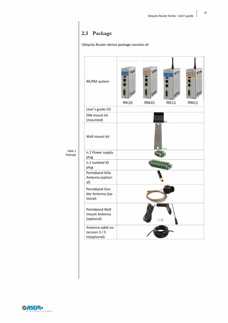
Table 1 Package
2.3 Package
Ubiquity Router device package consists of:
RK/RM system
RK10 RM10 RK11 RM11
User’s guide CD
DIN mount kit (mounted)
Wall mount kit
n.1 Power supply plug
n.1 Isolated IO plug Pentaband Stilo Antenna (option-al)
Pentaband Out-dor Antenna (op-tional)
Pentaband Wall mount Antenna (optional)
Antenna cable ex-tension 3 / 5 m(optional)

10
SECTION 2 - Description
Figure 1 RK10
2.4 Front view RK10
Reset LED (Yellow)
Run /Stop LED (Green/Red)
COM Rx LED
COM
WAN ETH2
LAN ETH1
USB
COM Tx LED (Green)
Remote Connection LED (Green)
Power LED (Green)
10
9
8
7
6
1
2
3
4
5
1
2
3
10
9
8
7
6
5
4

11
Ubiquity Router family - User’s guide
The following behaviors are defined:
- Steady lighted - Blinking - Continuous sequence of a blink codes with a short pause in between
to report a status - Single sequence of a blink code to report an event
LED Status Description
RESET Steady lighted Active when pressing the RESET button or when in presence of a not recoverable hardware fault.
POWER Steady lighted Active when the Ubiquity Router device is properly powered
RUN/STOP Steady Green Ubiquity started and connected to the server
Steady Red Ubiquity started but NOT connected to the server
Blinking Green Ubiquity started and connecting to the server
Blinking Red Ubiquity started but not connected to the server because not associated to any Domain
Sequence of 2 red blinks
connection attempt to a different domain than the first of the initial registration
Single 2 green blinks Configuration from USB stick successfully complet-ed
Single 2 red blinks User credential for Domain access not valid
Single 3 green blinks Ubiquity Router device update from USB stick suc-cessfully completed
Single 3 red blinks Ubiquity Router device updated from USB Stick failed
Single 4 red blinks Factory restore started
Single 5 red blinks Ubiquity Runtime execution error, will follow a system restart
Single 6 red blinks USB stick data format not correct or unknown er-ror
REMOTE CON-NECTION
Steady lighted Active when at least one Control Center client is connected to the RK10, otherwise off
COM Rx COM Tx
Signal presence These LEDs are directly connected to the serial port Rx/Tx signals and they show traffic through the lines

12
SECTION 2 - Description
2.5 Front view RM10
Reset LED (Yellow)
Run /Stop LED (Green/Red)
COM Rx LED
COM
WAN ETH2
LAN ETH1
USB
COM Tx LED (Green)
Remote Connection LED (Green)
Power LED (Green)
10
9
8
7
6
1
2
3
4
5
1
2
3
10
9
8
7
6
5
4

13
Ubiquity Router family - User’s guide
The following behaviors are defined:
- Steady lighted - Blinking - Continuous sequence of a blink codes with a short pause in between
to report a status - Single sequence of a blink code to report an event
LED Status Description
RESET Steady lighted Active when pressing the RESET button or when in presence of a not recoverable hardware fault.
POWER Steady lighted Active when the Ubiquity Router device is properly powered
RUN/STOP Steady Green Ubiquity started and connected to the server
Steady Red Ubiquity started but NOT connected to the server
Blinking Green Ubiquity started and connecting to the server
Blinking Red Ubiquity started but not connected to the server because not associated to any Domain
Sequence of 2 red blinks
connection attempt to a different domain than the first of the initial registration
Single 2 green blinks Configuration from USB stick successfully complet-ed
Single 2 red blinks User credential for Domain access not valid
Single 3 green blinks Ubiquity Router device update from USB stick suc-cessfully completed
Single 3 red blinks Ubiquity Router device updated from USB Stick failed
Single 4 red blinks Factory restore started
Single 5 red blinks Ubiquity Runtime execution error, will follow a system restart
Single 6 red blinks USB stick data format not correct or unknown er-ror
REMOTE CON-NECTION
Steady lighted Active when at least one Control Center client is connected to the RK10, otherwise off
COM Rx COM Tx
Signal presence These LEDs are directly connected to the serial port Rx/Tx signals and they show traffic through the lines
14
SECTION 2 - Description
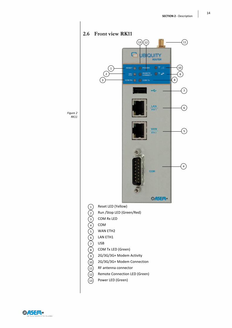
Figure 2 RK11
2.6 Front view RK11
Reset LED (Yellow)
Run /Stop LED (Green/Red)
COM Rx LED
COM
WAN ETH2
LAN ETH1
USB
COM Tx LED (Green)
2G/3G/3G+ Modem Activity
2G/3G/3G+ Modem Connection
RF antenna connector
Remote Connection LED (Green)
Power LED (Green)
10
9
13
12
11
8
7
6
1
2
3
4
5
1
2
3
10
11
8
7
6
5
4
9
13 12

15
Ubiquity Router family - User’s guide
The following behaviors are defined:
- Steady lighted - Blinking - Continuous sequence of a blink codes with a short pause in between
to report a status - Single sequence of a blink code to report an event
LED Status Description
RESET Steady lighted Active when pressing the RESET button or when in presence of a not recoverable hardware fault.
POWER Steady lighted Active when the Ubiquity Router device is properly powered
RUN/STOP Steady Green Ubiquity started and connected to the server
Steady Red Ubiquity started but NOT connected to the server
Blinking Green Ubiquity started and connecting to the server
Blinking Red Ubiquity started but not connected to the server because not associated to any Domain
Sequence of 2 red blinks
connection attempt to a different domain than the first of the initial registration
Single 2 green blinks Configuration from USB stick successfully complet-ed
Single 2 red blinks User credential for Domain access not valid
Single 3 green blinks Ubiquity Router device Update from USB stick suc-cessfully completed
Single 3 red blinks Ubiquity Router device Updated from USB Stick failed
Single 4 red blinks Factory restore started
Single 5 red blinks Ubiquity Runtime execution error, will follow a system restart
Single 6 red blinks USB stick data format not correct or unknown er-ror
REMOTE CON-NECTION
Steady lighted Active when at least one Control Center client is connected to the Router, otherwise off
COM Rx COM Tx
Signal presence These LEDs are directly connected to the serial port Rx/Tx signals and they show traffic through the lines
2G/3G/3G+ MODEM CON-NECTION
Steady red The modem has not detected network signal.
Blinking green The modem has detected a weak signal from the network.
Steady green The modem has detected a strong signal from the network.
Blinking red SIM error (e.g. wrong PIN).
2G/3G/3G+ MODEM ACTIV-ITY
Blinking green Modem currently connected.
Off Modem disconnected.

16
SECTION 2 - Description
Figure 3 RM11
2.7 Front view RM11
Reset LED (Yellow)
Run /Stop LED (Green/Red)
COM Rx LED
COM
WAN ETH2
LAN ETH1
USB
COM Tx LED (Green)
2G/3G/3G+ Modem Activity
2G/3G/3G+ Modem Connection
RF antenna connector
Remote Connection LED (Green)
Power LED (Green)
13
12
11
10
9
8
7
6
1
2
3
4
5
1
2
3
9
13
7
6
5
4
11
10
12
8

17
Ubiquity Router family - User’s guide
The following behaviors are defined:
- Steady lighted - Blinking - Continuous sequence of a blink codes with a short pause in between
to report a status - Single sequence of a blink code to report an event
LED Status Description
RESET Steady lighted Active when pressing the RESET button or when in presence of a not recoverable hardware fault.
POWER Steady lighted Active when the Ubiquity Router device is properly powered
RUN/STOP Steady Green Ubiquity started and connected to the server
Steady Red Ubiquity started but NOT connected to the server
Blinking Green Ubiquity started and connecting to the server
Blinking Red Ubiquity started but not connected to the server because not associated to any Domain
Sequence of 2 red blinks
connection attempt to a different domain than the first of the initial registration
Single 2 green blinks Configuration from USB stick successfully complet-ed
Single 2 red blinks User credential for Domain access not valid
Single 3 green blinks Ubiquity Router device Update from USB stick suc-cessfully completed
Single 3 red blinks Ubiquity Router device Updated from USB Stick failed
Single 4 red blinks Factory restore started
Single 5 red blinks Ubiquity Runtime execution error, will follow a system restart
Single 6 red blinks USB stick data format not correct or unknown er-ror
REMOTE CON-NECTION
Steady lighted Active when at least one Control Center client is connected to the Router, otherwise off
COM Rx COM Tx
Signal presence These LEDs are directly connected to the serial port Rx/Tx signals and they show traffic through the lines
2G/3G/3G+ MODEM CON-NECTION
Steady red The modem has not detected network signal.
Blinking green The modem has detected a weak signal from the network.
Steady green The modem has detected a strong signal from the network.
Blinking red SIM error (e.g. wrong PIN).
2G/3G/3G+ MODEM AC-TIVITY
Blinking green Modem currently connected.
Off Modem disconnected.

18
SECTION 2 - Description
Figure 4 RK10
2.8 UP view
Reset button
Restore factory defaults button
DC Input
Digital In / Out
Antenna connector (RM only)
RESET Forces the device restart. The command ensures a complete initiali-zation of all internal electronics and software. The visual feedback of the operation is returned by the RESET LED.
RESTORE FACTORY DEFAULT
Restores the Ubiquity Router device to factory settings. All the set-tings are reset, all the system software is restored to original ver-sions including the operating system, the firmware the Ubiquity Runtime and Domain registrations (identity is removed). To execute the restore, turn off the device, press and hold down the reset button and give power. You need to hold down the button for at least 10 seconds. The start-ing of the restore process is indicated by the dedicated blink se-quence of the LEDs. Wait for the process to be completed and system restart.
5
4
3
2
1
2 3 4 1
5

19
Ubiquity Router family - User’s guide
Figure 5 RK10
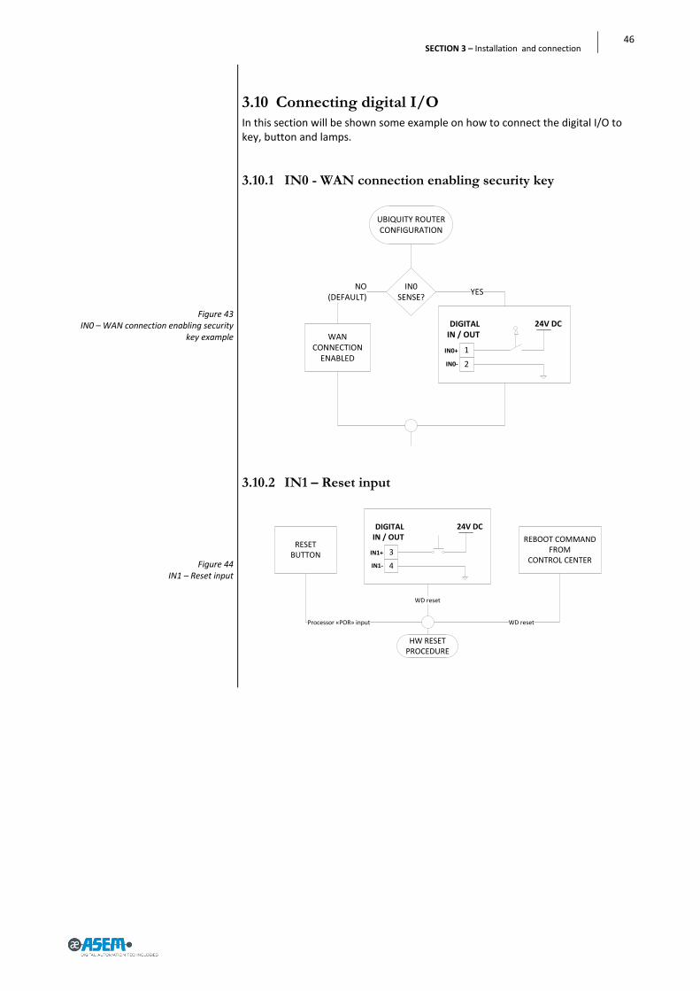
IN0 This input works as “Connection mode”, also referred as “selector key” in-put. By default the status of this input is ignored. When the Ubiquity Router device is configured to handle the input (see “General options” in the Ubiquity Router device configuration chapter) it can be used to control from outside the connection to the server. The input can be driven by a mechanical selector, by a key selector or by a PLC outputs.
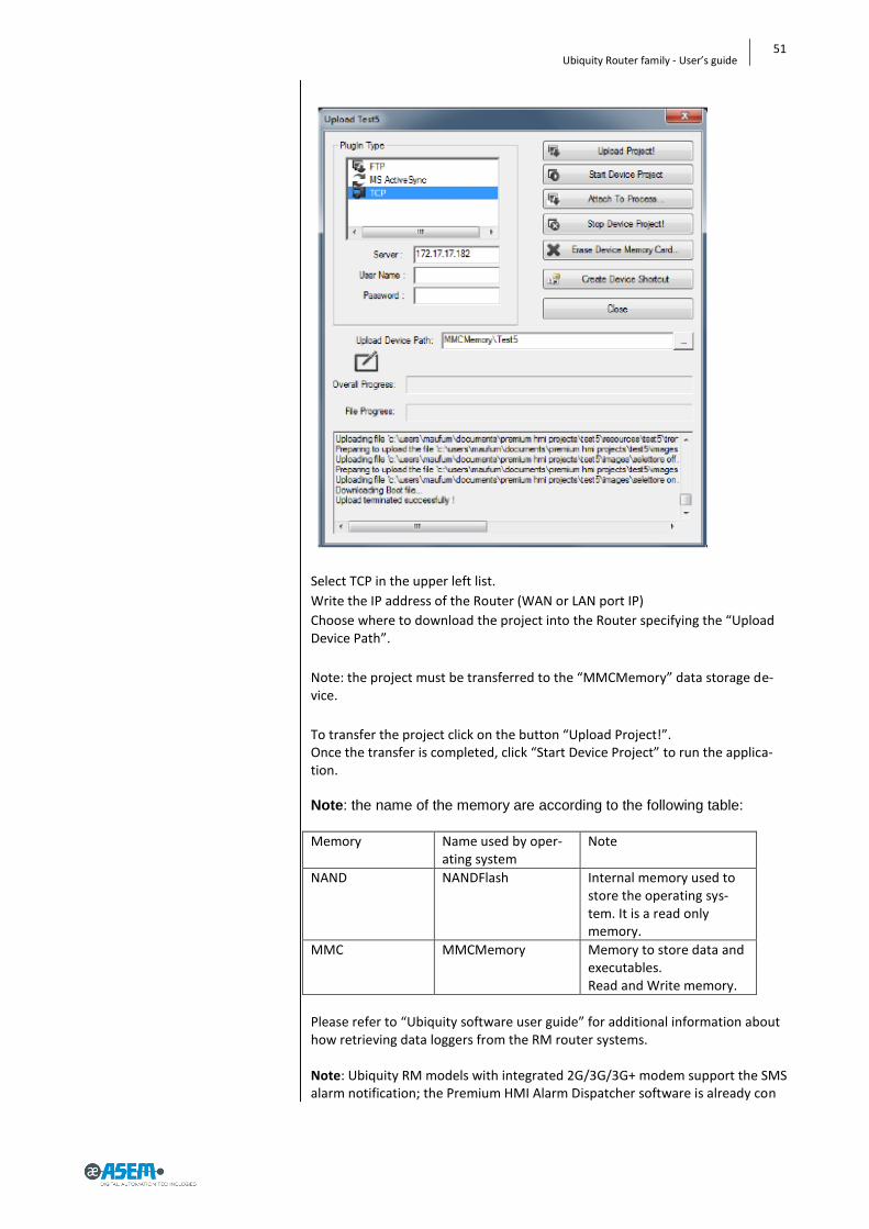
IN1 This input allows controlling the device restart from outside. The operation corresponds to the RESET button. Once the command is received a proper feedback is returned by the status LED.
OUT0
The output turns active when Ubiquity Router device is connected to the associated Domain. Note that the simple connection to the server does not activate the output, it is required that Ubiquity is successfully authenticat-ed to the Domain.
OUT1 The output is active when at least one Control Center client is connected to the Ubiquity Router device.
2.9 Right view
Full stainless steel enclosure
Aeration holes 2
1
1
2
2

20
SECTION 2 - Description
Figure 6 RK10
Figure 7 RK11/RM11
2.10 Left view
Full stainless steel enclosure
Aeration holes
2.11 Rear view (RK11/RK11 ET – RM11 / RM11 ET)
Wall book mounting plate holes
DIN rail book mounting hook holes
SIM card socket 3
2
1
2
1
1
2
1
1
2
1
1
2
2
3

21
Ubiquity Router family - User’s guide
Figure 8 RK10
2.12 Rear view (RK10/RK10 ET-RM10/RM10 ET)
Wall book mounting plate holes
DIN book mounting hook holes
2
1
1
2
1
1
2
1

22
SECTION 2 - Description
Figure 9 RK10
2.12.1 Labels
On the side panels there are the following labels:
LAN IP Mask WAN IP User Password
192.168.0.1 255.255.255.0 DHCP admin admin
MAC LAN code
MAC WAN code
Serial number
Bar Code
IMEI
5
1
6
4
3
2
1
2
3
4 5
6

23
Ubiquity Router family - User’s guide
Figure 10 RK10
DC Input pinout
Digital In / Out pinout
CE marking
Disposal
Electrical information
Model
COM pinout
Restore factory defaults button
Reset button
9
8
7
6
5
4
3
2
1
3
4 6
5
9
7
2
1
8

24
SECTION 2 - Description
Figure 11 RK11
Figure 12 Pentaband stilo antenna
SIM card insertion label
2.12.2 Antenna
2.12.2.1 Pentaband stilo antenna
RK11 direct mount or panel mount using extension cable
20W
0dBi
50 Ohms
48mm
SMA-M
1
1

25
Ubiquity Router family - User’s guide
Figure 13 Pentaband wall-mount antenna
2.12.2.2 Pentaband wall-mount antenna
5mt cable
wall mount with 90° bracket
IP67
50W
2,5dBi
50 Ohms
248mm
SMA-M

26
SECTION 2 - Description
Figure 14 Pentaband outdor antenna
2.12.2.3 Pentaband outdor antenna
3mt cable
outdoor panel mount
IP67
5W
3,2dBi
50 Ohms
48x50mm ▪ SMA-M

27
Ubiquity Router family - User’s guide
SECTION 3
3 Installation and connection
28
SECTION 3 – Installation and connection
Note: please refer to paragraph 2.3 Package.
Note: For installation in control cabinets and, in particular, in closed containers, make sure the recommended ambient temperature is maintained. For further details please refer to section 8.1 Technical specifications.
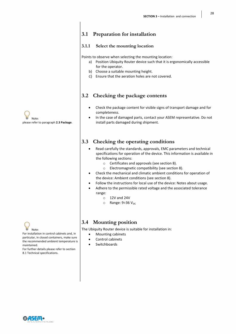
3.1 Preparation for installation
3.1.1 Select the mounting location
Points to observe when selecting the mounting location: a) Position Ubiquity Router device such that it is ergonomically accessible
for the operator. b) Choose a suitable mounting height. c) Ensure that the aeration holes are not covered.
3.2 Checking the package contents
Check the package content for visible signs of transport damage and for completeness.
In the case of damaged parts, contact your ASEM representative. Do not install parts damaged during shipment.
3.3 Checking the operating conditions
Read carefully the standards, approvals, EMC parameters and technical specifications for operation of the device. This information is available in the following sections:
o Certificates and approvals (see section 8). o Electromagnetic compatibility (see section 8).
Check the mechanical and climatic ambient conditions for operation of the device: Ambient conditions (see section 8).
Follow the instructions for local use of the device: Notes about usage.
Adhere to the permissible rated voltage and the associated tolerance range:
o 12V and 24V o Range: 9÷36 VDC
3.4 Mounting position
The Ubiquity Router device is suitable for installation in:
Mounting cabinets
Control cabinets
Switchboards

29
Ubiquity Router family - User’s guide
3.4.1 Damage due to overheating
The operative temperature must range between 0° and 50°C for Rx10, Rx11 devices.
The operative temperature must range between -20° and +70°C for Rx10-ET.
The operative temperature must range between -20° and +60°C for Rx11-ET devices.
Ubiquity Router device system is designed for book mounting position (both wall book mount and DIN book mount).
An inclined installation reduces the thermal convection of the device and the maximum permissible ambient temperature for operation. Please contact ASEM for details.
The device may otherwise be damaged and its certifications and warran-ty will be void.
3.5 Preparing the mounting
In order to ensure a proper mounting of the system, the material of the mounting frame must be sufficiently stable.
30
SECTION 3 – Installation and connection
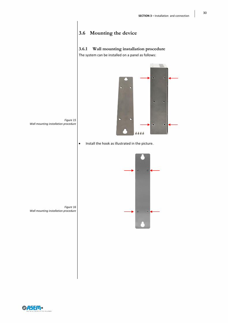
Figure 15 Wall mounting installation procedure
Figure 16 Wall mounting installation procedure
3.6 Mounting the device
3.6.1 Wall mounting installation procedure
The system can be installed on a panel as follows:
Install the hook as illustrated in the picture.

31
Ubiquity Router family - User’s guide
Figure 17 Wall mounting installation procedure
Figure 18 Wall mounting installation procedure
Figure 19 Wall mounting installation procedure
Figure 20 Wall mounting installation procedure
Drill the required holes on the housing panel according to the instructions detailed in the figure.
There are 2 fastening points. Fastening can be made using stainless steel screws M4x20.
Hang the system as shown in the figure.
Step 1: first lift and insert the top.
Step 2: align the bottom
Step 3: Release the top to match the slots with the screws.

32
SECTION 3 – Installation and connection
Figure 21 Wall mounting installation procedure
Step 4: Tighten two screws.

33
Ubiquity Router family - User’s guide
Figure 22 Wall mounting installation procedure
Figure 23 Wall mounting installation procedure
Figure 24 Wall mounting installation procedure
3.6.2 DIN guide mounting installation procedure
The system can be installed on a DIN guide as follows:
Install the DIN hook as illustrated in the picture.

34
SECTION 3 – Installation and connection
Figure 25 Wall mounting installation procedure
Figure 26 Wall mounting installation procedure
Hang the system to the DIN guide.
Example of correct installation.

35
Ubiquity Router family - User’s guide
Figure 27 Wall mounting installation procedure
To remove the system from the DIN guide:
Lift the system up and release it from the DIN guide
36
SECTION 3 – Installation and connection
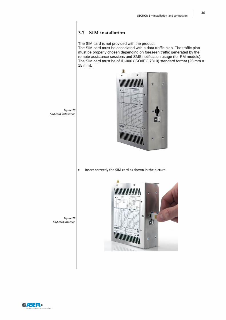
Figure 28 SIM card installation
Figure 29 SIM card insertion
3.7 SIM installation The SIM card is not provided with the product. The SIM card must be associated with a data traffic plan. The traffic plan must be properly chosen depending on foreseen traffic generated by the remote assistance sessions and SMS notification usage (for RM models). The SIM card must be of ID-000 (ISO/IEC 7810) standard format (25 mm × 15 mm).
Insert correctly the SIM card as shown in the picture

37
Ubiquity Router family - User’s guide
Figure 30 SIM card insertion
Figure 31 SIM card inserted (datail)
Pull the SIM card in the hole till you listen a “clic”

38
SECTION 3 – Installation and connection
Figure 32 Pentaband stilo antenna installation
Figure 33 Pentaband stilo antenna installation
3.7.1 Antenna Installation
3.7.1.1 Pentaband stilo antenna For dimension installation please refer to pararagraph 6.4
Drill a 6,5mm hole on the metal.
Recommended torque for mounting is 0.9 Nm.
Max thickness 2mm 6,5mm hole
39
Ubiquity Router family - User’s guide
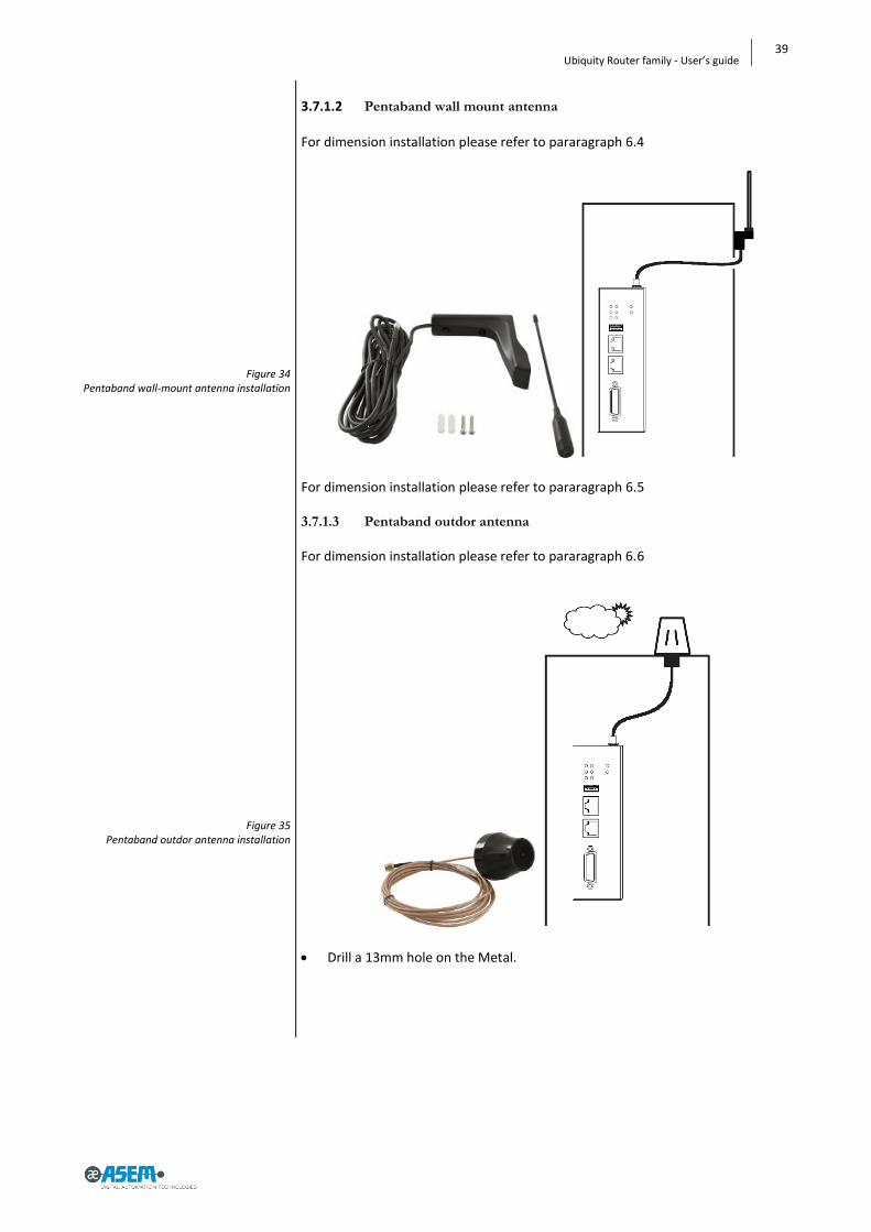
Figure 34 Pentaband wall-mount antenna installation
Figure 35 Pentaband outdor antenna installation
3.7.1.2 Pentaband wall mount antenna For dimension installation please refer to pararagraph 6.4
For dimension installation please refer to pararagraph 6.5 3.7.1.3 Pentaband outdor antenna
For dimension installation please refer to pararagraph 6.6
Drill a 13mm hole on the Metal.
40
SECTION 3 – Installation and connection
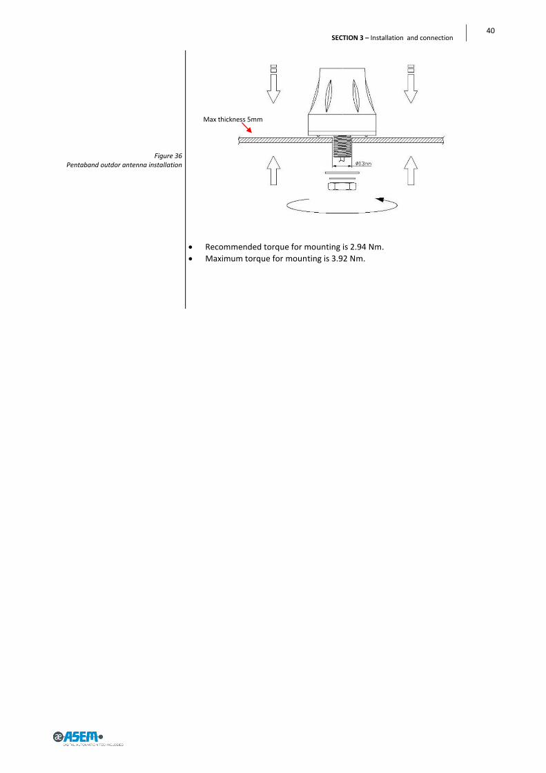
Figure 36 Pentaband outdor antenna installation
Recommended torque for mounting is 2.94 Nm.
Maximum torque for mounting is 3.92 Nm.
Max thickness 5mm

41
Ubiquity Router family - User’s guide
Attention: the system must be powered with a voltage of 12V or 24V (9V÷36V) DC.
Figure 37 Power supply connection detail
3.8 Connecting the device
3.8.1 Notes on connection
Ubiquity Router device must be installed in accordance with the indications contained in this operating instructions.
These devices are intended to be connected to a “Secondary Circuit Over-voltage Category II”
3.8.2 Grounding and bonding
Whenever two pieces of equipment connected to each other are far apart, it is possible that their ground connections could be at a different potential level. The data cable screens connecting the equipment’s chassis on one end and the Ubiquity Router device’s chassis on the other end can therefore be subject to a high current circulation capable of destroying the interface. To overcome this hazard such current must be steered away from the interface. To achieve this goal the following methods can be used:
1. Use an equipotential bonding cable (16mm
2, suitable at least 75C°) to con-
nect the equipment’s’ ground to the Ubiquity Router device’s ground. 2. Connect the data cable screens to the equipotential bonding rail on both
sides before connecting the cable to the interfaces.
3.8.3 Power supply connection
The device may only be connected to a 12V or 24V (maximum permissible operating voltage range 9V to 36V) power supply which satisfies the require-ments of safe extra low voltage (SELV) in accordance with IEC/EN/DIN EN/UL60950-1. The power supply has to fulfill the requirements NEC Class2 or LPS in accordance with IEC/EN/DIN EN/UL60950-1 Connect the device with a cable cross-section of 0.75 – 1.5 mm
2 (AWG18 to
AWG16 suitable at least 75C°).
Remove the three poles connector from the system.
Connect the positive pole, the negative and the ground one (also refer to the label on the back of the system) to the related terminals of the three pole connector.
+ (24V)
EMC Ground (0V)
- (0V)

42
SECTION 3 – Installation and connection
Figure 38
Power supply connection detail
Figure 39 Ethernet connection detail
3.8.4 Connecting the Ethernet ports
The Routers have always two Ethernet ports, one referred as WAN, the other one referred as LAN.
When using the cable connection for Internet, it must be connected to the WAN port. The LAN port shall be connected to the automation sub-network.
LAN for automation network
WAN for Internet connection
43
Ubiquity Router family - User’s guide
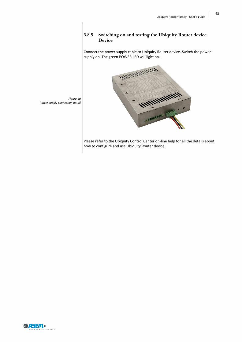
Figure 40 Power supply connection detail
3.8.5 Switching on and testing the Ubiquity Router device Device
Connect the power supply cable to Ubiquity Router device. Switch the power supply on. The green POWER LED will light on.
Please refer to the Ubiquity Control Center on-line help for all the details about how to configure and use Ubiquity Router device.

44
SECTION 3 – Installation and connection
Figure 41 DB9 connector detail
3.9 Connecting the serial port
A unique DB15 male connector hosts all serial protocols (please check par. 6.4.1 for pin-out details) so it is necessary to adapt this connection to plant needs; ASEM can supply connector adapters as optional parts but user can adapt DB15 connector by himself. For further details please contact ASEM
3.9.1 Connecting to MPI or PPI networks
The electrical specification of the MPI networks are often referring to the use of DB9 connectors like the one shown in the figure below.
The connector provides also the pass-through DB9 female connector for the MPI cable of the programming device.

45
Ubiquity Router family - User’s guide
Figure 42 Adapters detail
In order to support the use of the standard Profibus / MPI connectors available on the market, we suggest to use the cable converter (available as accessory) to transform the DB15-M connector of the panel COM port into the standard DB9-F required by the connectors. The adapter is shown in the following figure.
The internal connection are made according to the following table.
The line termination and polarization is normally realized by using resistors mounted internally to the standard Profibus / MPI connectors. The cable adapter provided by ASEM provides on the DB9-F connector side all the signals required by the MPI communication and line termination. The ASEM cable converter does NOT contain resistors for line termination. Present notes do not replace the official documentation about Profibus and MPI network wiring. Please refer to official specification for any additional detail. For further details, please contact ASEM
46
SECTION 3 – Installation and connection
Figure 43 IN0 – WAN connection enabling security
key example
Figure 44 IN1 – Reset input
3.10 Connecting digital I/O
In this section will be shown some example on how to connect the digital I/O to key, button and lamps.
3.10.1 IN0 - WAN connection enabling security key
DIGITAL IN / OUT
1
2
UBIQUITY ROUTERCONFIGURATION
IN0SENSE?
WAN CONNECTION
ENABLED
NO(DEFAULT)
IN0+
IN0-
24V DC
YES
3.10.2 IN1 – Reset input
DIGITAL IN / OUT
3
4
RESETBUTTON
Processor «POR» input
IN1+
IN1-
24V DC
WD reset
REBOOT COMMAND FROM
CONTROL CENTER
WD reset
HW RESET PROCEDURE

47
Ubiquity Router family - User’s guide
Figure 45 OUT0 – WAN connection enabling signal-
ling example
Figure 46 OUT0 – WAN connection enabling signal-
ling example
Figure 47 OUT0 – Remote assistance service running
example
Figure 48 OUT0 – Remote assistance service running
example
3.10.3 OUT0 - WAN connection enabled signalling
DIGITAL IN / OUT
5
6
OUT0A
OUT0B
24V DCmax
200mA
DIGITAL IN / OUT
5
6
OUT0A
OUT0B
24V DC
max 200mA
230V AC
3.10.4 OUT0 – Remote assistance service running
DIGITAL IN / OUT
7
8
OUT1A
OUT1B
24V DCmax
200mA
DIGITAL IN / OUT
7
8
OUT1A
OUT1B
24V DC
max 200mA
230V AC

48
SECTION 3 – Installation and connection

49
Ubiquity Router family - User’s guide
SECTION 4
4 Commissioning

50
SECTION 5 – Commissioning a project
4.1 Configuring
Ubiquity Router device system software is designed to reduce as much as pos-sible the user intervention and simplify the few mandatory settings. No settings is required for VPN and for the bridging of the Ethernet interfaces. All basic settings are made at factory level. No changes are requested to the us-er.
The Ubiquity Router device configuration is limited to the network interfaces IP addresses, to the serial port configuration, to the connection mode and Domain registration. Ubiquity Router device can be configured in two ways: • Using a network connection • Using a USB stick on which the configuration file was copied In both cases the configuration is done using Ubiquity Control Center. Please refer to the Ubiquity Control Center on-line help for all the instructions about how to configure and make the Ubiquity Router device commissioning. Ubiquity Router device requires for the configuration Ubiquity Control Center version 2 or above. Control Center is available for download in the dedicated product section of the www.asem.it web site.
4.1.1 Ubiquity Router RM models
Ubiquity Router devices with data monitoring functionality (RM models) can be additionally configured to run a Premium HMI project for data collection, alarm notification and web visualization. Those models come out from production already configured with all the re-quired application software and they are ready to be programmed by means of a standard Premium HMI Studio. Note: The RM systems are featuring Premium HMI Runtime Advanced foir WinCE and they must be programmed using Premium HMI Studio version 4 or above. To transfer a Premium HMI project to a Ubiquity Router RM device, you just need to specify in the Premium HMI transfer dialog the IP address of the router and provide the path for file storage in the router internal memory. Start Premium HMI Developing tool.
Load the project to transfer.
Click on the transfer icon (see picture below).
The following window will appear:
51
Ubiquity Router family - User’s guide
Select TCP in the upper left list.
Write the IP address of the Router (WAN or LAN port IP)
Choose where to download the project into the Router specifying the “Upload Device Path”.
Note: the project must be transferred to the “MMCMemory” data storage de-vice.
To transfer the project click on the button “Upload Project!”. Once the transfer is completed, click “Start Device Project” to run the applica-tion. Note: the name of the memory are according to the following table:
Memory Name used by oper-ating system
Note
NAND NANDFlash Internal memory used to store the operating sys-tem. It is a read only memory.
MMC MMCMemory Memory to store data and executables. Read and Write memory.
Please refer to “Ubiquity software user guide” for additional information about how retrieving data loggers from the RM router systems. Note: Ubiquity RM models with integrated 2G/3G/3G+ modem support the SMS alarm notification; the Premium HMI Alarm Dispatcher software is already con

52
SECTION 5 – Commissioning a project
figured to use the internal modem, you just need to configure the alarm thresholds according to the application requirements. Please see the Premium HMI Studio on-lien help for further information about how to setup alarm notification via SMS Note: Ubiquity RM models without integrated modem, DO NOT support alarm notification via SMS. Only notification via email is supported.

53
Ubiquity Router family - User’s guide
SECTION 5
5 Maintenance and care

54
SECTION 6 – Maintenance and care
Figure 49 Backup battery replacement
Figure 50 Backup battery replacement
5.1 Maintaining & cleaning
Ubiquity Router device is designed for maintenance-free operation except for the replacing of the battery backup when necessary.
Attention: Do not use detergents, solvents, cleaners or objects that could scratch the surface.
Attention: switch off the power before any cleaning operation.
5.1.1 Backup battery replacement (CR1220 3V)
Remove the two columns as indicated in figure.

55
Ubiquity Router family - User’s guide
Figure 51 Backup battery replacement
Figure 52 Backup battery replacement
Remove the screw as indicated in figure.
Locate the battery position.

56
SECTION 6 – Maintenance and care
Figure 53 Backup battery replacement
Figure 54 Backup battery replacement
Remove the battery.

57
Ubiquity Router family - User’s guide
Figure 55 Backup battery detail
Figure 56 SIM card socket
Replace it with one of the same model (CR2032 3V).
5.2 Backup and restore
Ubiquity Router device supplies tools to backup and restore the contents of its internal memory in order to manage the configuration and the operating sys-tem of Ubiquity Router device. For more information please see the Ubiquity Control Center on-line manual or contact the ASEM support center.
5.3 Updating the system
Ubiquity Router device is a hardware device that works thanks to a set of soft-ware components; they can be divided in: • Firmware • Ubiquity Runtime • Premium HMI Runtime (for RM models only)
All the Ubiquity Router device software components can be changed using a very simple procedure, fully automatic, safe and fast. The software components upgrades are distributed in the format of a single file that works as “container” for the components to be replaced.
To execute an update copy the “.asr” file on the root folder of an USB Stick. Plug the USB Stick into the Ubiquity Router device USB port and cycle the power. During the power up phase, the Ubiquity Router device recognizes the presence of the USB Stick with the update and it will immediately start the system soft-ware update procedure.

58
SECTION 6 – Maintenance and care
A proper visual feedback will in-form about the status of the oper-ation. No action is requested by the user. The update is completed after the Ubiquity Router device is auto-matically restarted. Please contact the technical sup-port for further information.
5.4 Technical support & repairs
ASEM offers wide-ranging, complete after-sales technical support. The staff who deal with this handle questions on the entire range of products skillfully, quickly, and efficiently. You can phone our staff in the service department, and they will give you com-plete, prompt advice on how to resolve your problems. telephone: +39 0432 967250 fax: +39 0432 967480 e-mail: [email protected]
5.5 Recycling and disposal
Ubiquity Router device can be recycled due to the use of materials with low en-vironmental impact. Contact a certified disposal service company for environ-mentally sound recycling and disposal of your old devices.

59
Ubiquity Router family - User’s guide
SECTION 6
6 Technical specifications

60
SECTION 8 - Technical specifications
Table 2 System software characteristics
Table 3 System hardware characteristics
Table 4 Electrical characteristics
Table 5 Mechanical characteristics
6.1 Technical specifications
System software characteristics Integrated sys-tem software
Operating System Microsoft Windows Embedded Com-pact 7 (C7P)
Other software ASEM Ubiquity runtime firmware
System hardware characteristics
Motherboard Model All-in-one, ASEM R171 RTC Hardware with battery backup
CPU RK10 Processor ARM Cortex A8 - Freescale i.MX535 - 1 GHz
Memory bus 400MHz
CPU RK10ET Processor ARM Cortex A8 - Freescale i.MX537 - 800 MHz
Memory bus 400MHz
System memory Type / Size / Socket 512 MB, / DDR3-800 / Soldered
Serial interfaces Type 1 x RS232/422/485 (DB15M) software se-lectable
Optoisolation Yes
Ethernet interfaces Type 1 x 10/100Mbps WAN (RJ45) with Link/Activity leds 1 x 100Mbps LAN (RJ45) with Link/Activity leds
2G/3G/3G+ modem (only for RK/RM11)
Type provides data service under global GSM/GPRS/EDGE/WCDMA networks (14.4Mbps downlink data rate)
USB interfaces Type 1 x USB 2.0 (TYPE-A, host port, software switch off)
Mass storage Internal / not re-movable
NAND-FLASH: 256 MB (Read Only) for Operative System and other system software. eMMC: 2/4 GB - 8 bit v. 4.4 compatible (application software and Ubiquity Runtime)
Battery Type Coin (CR1220 3V) removable non rechargeable Lifetime 3 years
Buttons, LEDs and keys
Reset Button Factory Recovery Button
System User
LEDs Reset Power Run / Stop Remote Connection COM Rx COM Tx 2G/3G/3G+ Modem. activity Modem connection
Electrical characteristics
Power supply Type Integrated on board, auto ranging
Input voltage 9÷36 VDC with 3 poles connector
Protections Anti-inversion polarity, over-voltage, fuse soldered on the board
These devices are intended to be connected to a “Secondary Circuit Overvoltage Category II”
Mechanical characteristics
Case Type Book mount
Material Steel, white zinc galvanizing

61
Ubiquity Router family - User’s guide
Table 6 Environmental characteristics
Table 7 Panel antenna characteristics
Table 8 Wall mount Panel antenna characteristics
Environmental characteristics
Temp. RK10, RM10, RK11, RM11
Operation -0° ÷ +50°C
Storage -20° ÷ +60°C
Temp. RK10ET, RM10ET
Operation -20° ÷ +70°C
Storage -30° ÷ +80°C
Temp. RK11ET, RM11ET
Operation -20° ÷ +60°C
Storage -30° ÷ +80°C
Humidity Operation/Storage 80% (non-condensing)
Panel antenna characteristics Electrical Frequency range 800MHz to 2200MHz Bands GSM-DCS-PCS-UMTS-CDMA-GPRS-EDGE-HSPA
VSWR ≤ 2.3 Polarization Linear
Power handling 20 W Impedance 50 Ohms
Connector Straight SMA(M) Environmental & Mechanical
Temperature -40° to +85°C Radome color Black
Radome material Pu Weight 6 g
Wall mount Panel antenna characteristics
Cellular Frequency (MHz)
824 ~ 896 880 ~ 960 1710 ~ 1880 1850 ~ 1990 1710 ~ 2170
Peak Gain (dBi)
Free Space -0.7 -0.9 1.7 2.5 2.2 L - Bracket 4.0 3.6 2.8 3.8 3.3
Average Gain (dBi) Free Space -5.7 -5.3 -2.2 -2.1 -2.3
L - Bracket -1.7 -1.8 -2.2 -1.7 -1.9 Efficiency Free Space 27% 30% 61% 62% 60%
L - Bracket 69% 66% 59% 68% 65% Impedance 50Ω
Polarization Linear Radiation Pattern Omni
Input Power 50 W Mechanical
Dimensions Height 248 ± 5 mm Base Diameter 17.08 ± 0.2 mm
Whip Diameter 4 ± 0.2 mm Casing ABS
Connector SMA Male Environmental & Mechanical Temperature range -40° to +85°C
Humidity Non condensing 65°C 95% RH

62
SECTION 8 - Technical specifications
Table 9 Outdor Panel antenna characteristics
Outdoor Panel antenna characteristics
Electrical
Antenna G30 Standard 2G/3G/4G
Operation Frequency (MHz) 698~960 MHz 1710~2170 MHz 2500~2800MHz Peak Gain 1.2 dBi 3.2dBi 2.5dBi
Average Gain -4.5 dB -2.5dB -4.5dB
Efficiency 40% 55% 40% VSWR <3.0:1
Impedance 50Ω
Polarization Linear Radiation Properties Omni-directional
Max Input Power 5 W Mechanical
Dimensions (mm) Height=48mm and Diameter=50mm
Cable Length=1m RG316* Casing UV Resistant ABS
Base and Thread Nickel plated Copper Connector SMA(M) Fully Customizable
Nut Nut M12
Sealant Rubber Stopper
63
Ubiquity Router family - User’s guide
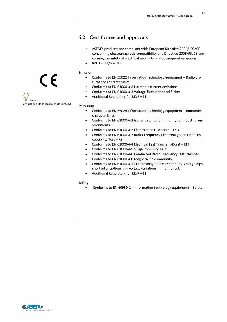
Note: For further details please contact ASEM
6.2 Certificates and approvals
ASEM’s products are compliant with European Directive 2004/108/CE concerning electromagnetic compatibility and Directive 2006/95/CE con-cerning the safety of electrical products, and subsequent variations.
RoHs 2011/65/UE. Emission
Conforms to EN 55022 Information technology equipment – Radio dis-turbance characteristics.
Conforms to EN 61000-3-2 Harmonic current emissions.
Conforms to EN 61000-3-3 Voltage fluctuations ad flicker.
Additional Regulatory for RK/RM11 Immunity
Conforms to EN 55024 Information technology equipment – Immunity characteristics.
Conforms to EN 61000-6-2 Generic standard immunity for industrial en-vironments.
Conforms to EN 61000-4-2 Electrostatic Discharge – ESD.
Conforms to EN 61000-4-3 Radio-Frequency Electromagnetic Field Sus-ceptibility Test – RS.
Conforms to EN 61000-4-4 Electrical Fast Transient/Burst – EFT.
Conforms to EN 61000-4-5 Surge Immunity Test.
Conforms to EN 61000-4-6 Conducted Radio Frequency Disturbances.
Conforms to EN 61000-4-8 Magnetic field immunity.
Conforms to EN 61000-4-11 Electromagnetic compatibility-Voltage dips, short interruptions and voltage variations immunity test.
Additional Regulatory for RK/RM11 Safety
Conforms to EN 60950-1 – Information technology equipment – Safety

64
SECTION 8 - Technical specifications
Figure 57 Dimensions
6.3 Dimension drawings

65
Ubiquity Router family - User’s guide
Figure 58 Dimensions

66
SECTION 8 - Technical specifications
Figure 59 Panel antenna drawing dimensions
6.4 Panel antenna drawing dimensions

67
Ubiquity Router family - User’s guide
Figure 60 Wall mount antenna drawing dimensions
6.5 Wall mount antenna drawing dimensions
1 Main bracket
2 Back bracket
3 3”8L screw
4 Cap
5 4”25L screw
6 6”24L wall mount stud
7 CFD 200 cable
8 SMA(M) ST
9 Heat shrink tube
10 Housing
11 Flexible whip

68
SECTION 8 - Technical specifications
Figure 61 Outdoor panel antenna drawing dimen-
sions
6.6 Outdoor panel antenna drawing dimensions
1 Housing top
2 Housing bottom
3 Gasket
4 Multi tooth washer
5 Nut M12
6 RG316
7 Heat shrink tube
8 SMA(M) ST
9 O-ring

69
Ubiquity Router family - User’s guide
Table 10 COM1 – DB15M Serial
Table 11 Digital In/Out
6.7 Ports PINOUT
6.7.1 COM1 – DB15M Serial
PIN Signal I/O
1 Isolated +5 VDC OUT
2 Transmit Data (RS-232) OUT
3 Receive Data (RS-232) IN
4 Request To Send OUT
5 Clear To Send IN
6 Data Set Ready IN
7 Isolated Ground 8 Data Terminal Ready OUT
9 Carrier Detect IN
10 Transmit Data +/Receive Data + (RS-485/RS-422) I/O
11 Transmit Data -/Receive Data - (RS-485/RS-422) I/O
12 Ring Indication (RS-232) IN
13 Receive Data + (RS-422) IN
14 Receive Data - (RS-422) IN
15 N.C.
Any polarization or termination resistor connected to RS422/485 channel, if required, it has to be provided by the user.
6.7.2 Digital In/Out
PIN Signal
1 IN 0 +
2 IN 0 -
3 IN 1 +
4 IN 1 -
5 OUT 0 - A
6 OUT 0 - B
7 OUT 1 - A
8 OUT 1 - B
70
SECTION 8 - Technical specifications
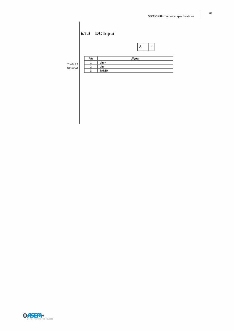
Table 12 DC Input
6.7.3 DC Input
PIN Signal
1 Vin +
2 Vin -
3 EARTH

Index of figures
Figure 1 RK10 .................................................................................................................................................................... 10 Figure 2 RK11 .................................................................................................................................................................... 14 Figure 3 RM11 ................................................................................................................................................................... 16 Figure 4 RK10 .................................................................................................................................................................... 18 Figure 5 RK10 .................................................................................................................................................................... 19 Figure 6 RK10 .................................................................................................................................................................... 20 Figure 7 RK11/RM11 ......................................................................................................................................................... 20 Figure 8 RK10 .................................................................................................................................................................... 21 Figure 9 RK10 .................................................................................................................................................................... 22 Figure 10 RK10 .................................................................................................................................................................. 23 Figure 11 RK11 .................................................................................................................................................................. 24 Figure 12 Pentaband stilo antenna ................................................................................................................................... 24 Figure 13 Pentaband wall-mount antenna ....................................................................................................................... 25 Figure 14 Pentaband outdor antenna ............................................................................................................................... 26 Figure 15 Wall mounting installation procedure .............................................................................................................. 30 Figure 16 Wall mounting installation procedure .............................................................................................................. 30 Figure 17 Wall mounting installation procedure .............................................................................................................. 31 Figure 18 Wall mounting installation procedure .............................................................................................................. 31 Figure 19 Wall mounting installation procedure .............................................................................................................. 31 Figure 20 Wall mounting installation procedure .............................................................................................................. 31 Figure 21 Wall mounting installation procedure .............................................................................................................. 32 Figure 22 Wall mounting installation procedure .............................................................................................................. 33 Figure 23 Wall mounting installation procedure .............................................................................................................. 33 Figure 24 Wall mounting installation procedure .............................................................................................................. 33 Figure 25 Wall mounting installation procedure .............................................................................................................. 34 Figure 26 Wall mounting installation procedure .............................................................................................................. 34 Figure 27 Wall mounting installation procedure .............................................................................................................. 35 Figure 28 SIM card installation ......................................................................................................................................... 36 Figure 29 SIM card insertion ............................................................................................................................................. 36 Figure 30 SIM card insertion ............................................................................................................................................. 37 Figure 31 SIM card inserted (datail).................................................................................................................................. 37 Figure 32 Pentaband stilo antenna installation ................................................................................................................ 38 Figure 33 Pentaband stilo antenna installation ................................................................................................................ 38 Figure 34 Pentaband wall-mount antenna installation .................................................................................................... 39 Figure 35 Pentaband outdor antenna installation ............................................................................................................ 39 Figure 36 Pentaband outdor antenna installation ............................................................................................................ 40 Figure 37 Power supply connection detail ........................................................................................................................ 41 Figure 38 Power supply connection detail ........................................................................................................................ 42 Figure 39 Ethernet connection detail ................................................................................................................................ 42 Figure 40 Power supply connection detail ........................................................................................................................ 43 Figure 41 DB9 connector detail ......................................................................................................................................... 44 Figure 42 Adapters detail .................................................................................................................................................. 45 Figure 43 IN0 – WAN connection enabling security key example ..................................................................................... 46 Figure 44 IN1 – Reset input ............................................................................................................................................... 46 Figure 45 OUT0 – WAN connection enabling signalling example ..................................................................................... 47 Figure 46 OUT0 – WAN connection enabling signalling example ..................................................................................... 47 Figure 47 OUT0 – Remote assistance service running example ........................................................................................ 47 Figure 48 OUT0 – Remote assistance service running example ........................................................................................ 47 Figure 49 Backup battery replacement ............................................................................................................................. 54 Figure 50 Backup battery replacement ............................................................................................................................. 54 Figure 51 Backup battery replacement ............................................................................................................................. 55 Figure 52 Backup battery replacement ............................................................................................................................. 55 Figure 53 Backup battery replacement ............................................................................................................................. 56 Figure 54 Backup battery replacement ............................................................................................................................. 56 Figure 55 Backup battery detail ........................................................................................................................................ 57 Figure 56 SIM card socket ................................................................................................................................................. 57 Figure 57 Dimensions ........................................................................................................................................................ 64

Figure 58 Dimensions ........................................................................................................................................................ 65 Figure 59 Panel antenna drawing dimensions .................................................................................................................. 66 Figure 60 Wall mount antenna drawing dimensions ........................................................................................................ 67 Figure 61 Outdoor panel antenna drawing dimensions ................................................................................................... 68
Index of tables
Table 1 Package .................................................................................................................................................................. 9 Table 2 System software characteristics ........................................................................................................................... 60 Table 3 System hardware characteristics ......................................................................................................................... 60 Table 4 Electrical characteristics ....................................................................................................................................... 60 Table 5 Mechanical characteristics ................................................................................................................................... 60 Table 6 Environmental characteristics .............................................................................................................................. 61 Table 7 Panel antenna characteristics .............................................................................................................................. 61 Table 8 Wall mount Panel antenna characteristics .......................................................................................................... 61 Table 9 Outdor Panel antenna characteristics .................................................................................................................. 62 Table 10 COM1 – DB15M Serial ........................................................................................................................................ 69 Table 11 Digital In/Out ..................................................................................................................................................... 69 Table 12 DC Input.............................................................................................................................................................. 70
ASEM S.p.A. Via Buia, 4 33011 Artegna (UD) Italy Tel. +39/0432-9671 Fax. +39/0432-977465 Via Prealpi, 13/A 20034 Giussano (MI) Italy Tel. +39/0362-859111 Fax. +39/0362-859121 [email protected] www.asem.it