ASEE 2014 Zone I Conference, April 3-5, 2014, University ... · PDF file... One called...
6
ASEE 2014 Zone I Conference, April 3-5, 2014, University of Bridgeport, Bridgpeort, CT, USA. Bio-MEMS Thermally-Actuated Micropump Shiangyu Lin Department of Biomedical Science & Engineering University of Bridgeport Bridgeport, CT 06604 [email protected] Junyi Zou Department of Biomedical Engineering University of Bridgeport Bridgeport, CT 06604 [email protected] Xingguo Xiong Department of Electrical Engineering University of Bridgeport Bridgeport, CT 06604 [email protected] Prabir Patra Department of Biomedical Engineering University of Bridgeport Bridgeport, CT 06604 [email protected] Abstract — In this paper, the design and simulation of a MEMS thermal actuated micropump is reported. The micropump consists of a microfluic chamber on top of a thermal actuation chamber. Passive microvalves are embedded in the inlet and outlet of the pump to allow one-way flow of the microfluid. The thermal actuation chamber has sealed air inside it. A thermal resistor is embedded in the bottom surface of the actuation chamber. The top surface of actuation chamber is made by flexible thin silicon membrane. When a voltage is applied to the thermal resistor, the generated Joule heat raises the temperature of the sealed air in the actuation chamber. As a result, the air expands and presses the top membrane to bend up. In turn, the microfluid in the top chamber is pumped into the outlet. When the voltage is removed, the sealed air cools down due to thermal dissipation, and the silicon membrane becomes flat. Thus new fluid is sucked into the microfluidic chamber via inlet. The working principle of the micropump is analyzed in detail. Based on the theoretical analysis, a set of optimized design parameters of the micropump are suggested. ANSYS simulation is used to verify the function of the micropump. The proposed micropump can be used for lab-on-a-chip and micro drug delivery applications. Keywords—(Microelectromechanical Systems (MEMS), micropump, ANSYS simulation I. INTRODUCTION Micropump is a MEMS technology of special interest in micro fluidic research, and has become available for industrial product integration in recent years. Micropumps were started in middle 1970s. Before 1990s, mechanical pumps were mainly studied. After 1990s, non-mechanical pumps were introduced. Their miniaturized overall size, potential cost and improved dosing. One of the first documents about micro pump was presented by Thomas and Bessman in 1975. It contain muti piezoelectric disc benders combine with solenoid valve and pumping chamber. It was designing for implantation for human body. 1984 Smits was patented the silicon micro fabrication technologies. Few years later, he published the peristaltic pump in 1990. This pump consists of three piezoelectric discs and purpose was for his insulin delivery systems. In this chapter we are brief overview of a variety of micropumps and their applications. The review will present key features of micropumps such as actuation methods, working principles, construction, performance parameters and their medical applications. In general, micropumps can roughly be divided into two groups: One called “mechanical” micro pump. The micro pump that have moving mechanical parts such as pumping diaphragm and check valves that use the oscillatory or rotational forces to control micro fluid. The most popular mechanical micropumps such like electrostatic, piezoelectric, shape memory alloy (SMA), bimetallic, ionic conductive polymer film (ICPF), electromagnetic and phase change type. Another one is non mechanical micropump. Non mechanical type of micropump has to transform certain available non-mechanical force into kinetic momentum so that the fluid in micro channels can be driven. This type often consists of two check valves and a chamber with movable membrane. By some mechanisms, membrane can be actuated to change the volume of chamber. Non-mechanical micropumps include magneto hydrodynamic (MHD), electro hydrodynamic (EHD), electro osmotic, electro wetting, bubble type, flexural planar wave (FPW), electrochemical and evaporation based micropump. Based on these two types can be further subdivided into several subtypes. Here lists some most common types of micropump: i.Phase change type micropump ii.Rotary micropump iii.Piezoelectric micropump iv.Shape memory alloy micropump v.Electrostatic micropump vi.Bimetallic micropump
Transcript of ASEE 2014 Zone I Conference, April 3-5, 2014, University ... · PDF file... One called...
ASEE 2014 Zone I Conference, April 3-5, 2014, University of Bridgeport, Bridgpeort, CT, USA.
Bio-MEMS Thermally-Actuated Micropump Shiangyu Lin
Department of Biomedical Science & Engineering University of Bridgeport
Bridgeport, CT 06604 [email protected]
Junyi Zou
Department of Biomedical Engineering University of Bridgeport
Bridgeport, CT 06604 [email protected]
Xingguo Xiong Department of Electrical Engineering
University of Bridgeport Bridgeport, CT 06604
Prabir Patra Department of Biomedical Engineering
University of Bridgeport Bridgeport, CT 06604 [email protected]
Abstract — In this paper, the design and simulation of a MEMS thermal actuated micropump is reported. The micropump consists of a microfluic chamber on top of a thermal actuation chamber. Passive microvalves are embedded in the inlet and outlet of the pump to allow one-way flow of the microfluid. The thermal actuation chamber has sealed air inside it. A thermal resistor is embedded in the bottom surface of the actuation chamber. The top surface of actuation chamber is made by flexible thin silicon membrane. When a voltage is applied to the thermal resistor, the generated Joule heat raises the temperature of the sealed air in the actuation chamber. As a result, the air expands and presses the top membrane to bend up. In turn, the microfluid in the top chamber is pumped into the outlet. When the voltage is removed, the sealed air cools down due to thermal dissipation, and the silicon membrane becomes flat. Thus new fluid is sucked into the microfluidic chamber via inlet. The working principle of the micropump is analyzed in detail. Based on the theoretical analysis, a set of optimized design parameters of the micropump are suggested. ANSYS simulation is used to verify the function of the micropump. The proposed micropump can be used for lab-on-a-chip and micro drug delivery applications.
Keywords—(Microelectromechanical Systems (MEMS), micropump, ANSYS simulation
I. INTRODUCTION Micropump is a MEMS technology of special interest in
micro fluidic research, and has become available for industrial product integration in recent years. Micropumps were started in middle 1970s. Before 1990s, mechanical pumps were mainly studied. After 1990s, non-mechanical pumps were introduced. Their miniaturized overall size, potential cost and improved dosing. One of the first documents about micro pump was presented by Thomas and Bessman in 1975. It contain muti piezoelectric disc benders combine with solenoid valve and pumping chamber. It was designing for implantation for human body. 1984 Smits was patented the silicon micro fabrication technologies. Few years later, he published the peristaltic pump in 1990. This pump consists of three
piezoelectric discs and purpose was for his insulin delivery systems. In this chapter we are brief overview of a variety of micropumps and their applications. The review will present key features of micropumps such as actuation methods, working principles, construction, performance parameters and their medical applications.
In general, micropumps can roughly be divided into two groups: One called “mechanical” micro pump. The micro pump that have moving mechanical parts such as pumping diaphragm and check valves that use the oscillatory or rotational forces to control micro fluid. The most popular mechanical micropumps such like electrostatic, piezoelectric, shape memory alloy (SMA), bimetallic, ionic conductive polymer film (ICPF), electromagnetic and phase change type.
Another one is non mechanical micropump. Non mechanical type of micropump has to transform certain available non-mechanical force into kinetic momentum so that the fluid in micro channels can be driven. This type often consists of two check valves and a chamber with movable membrane. By some mechanisms, membrane can be actuated to change the volume of chamber. Non-mechanical micropumps include magneto hydrodynamic (MHD), electro hydrodynamic (EHD), electro osmotic, electro wetting, bubble type, flexural planar wave (FPW), electrochemical and evaporation based micropump.
Based on these two types can be further subdivided into several subtypes. Here lists some most common types of micropump:
i.Phase change type micropump
ii.Rotary micropump
iii.Piezoelectric micropump
iv.Shape memory alloy micropump
v.Electrostatic micropump
vi.Bimetallic micropump
vii.Electromagnetic micropump
viii.Electroosmotic micropump
ix.Diffuser micropump
x.Electro-wetting micropump
Compared with this paper, there are some others thermal micropump are introduced. A Thermal Bubble Actuated Micro Nozzle-Diffuser Pump. A thermal-bubble-actuated micropump by the principles of liquid/vapor phase transition and nozzle-diffuser flow regulation is successfully demonstrated. The actuation mechanism comes from periodically nucleating and collapsing thermal bubbles. A net flow is generated from the nozzle to the diffuser by the nozzle-diffuser flow controller. As an application example in a microfluidic device, this valve-less micropump is used in a microfluidic system to enhance the fluid mixing by agitating the flows. Analysis of Material Properties for Thin Film Membrane in Thermal Actuated Micropump. That paper from IEEE presents a comparison of thin film materials used as movable membrane for thermal actuated micropump. The materials discussed are PMMA, polyimide, silicon nitride (Si3N4) and single crystal silicon. The properties of membrane material are characterized using Finite Element Analysis (FEA) to study its mechanical and physical behavior that are suitable to be used as an actuator for thermal micropump.
II. MICROPUMP DESIGN 2.1 working principle
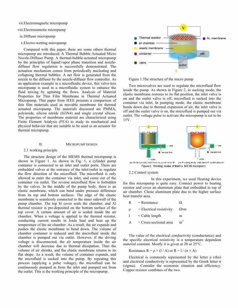
The structure design of the MEMS thermal micropump is shown in Figure 1. As shown in Fig. 1, a cylinder pump container is connected to an inlet and outlet ports. There are embedded valves at the entrance of the inlet/outlet to regulate the flow direction of the microfluid. The microfluid is only allowed to enter the container via inlet, and come out of the container via outlet. The reverse microfluid flow is forbidden by the valves. In the middle of the pump body, there is an elastic membrane, which can bend under pressure difference from its top and bottom surfaces. The edge of the elastic membrane is seamlessly connected to the inner sidewall of the pump chamber. The top Si cover seals the chamber, and Al thermal resistor is pre-deposited on the bottom surface of the top cover. A certain amount of air is sealed inside the air chamber. When a voltage is applied to the thermal resistor, conducting current results in Joule heat and heat up the temperature of the air chamber. As a result, the air expands and pushes the elastic membrane to bend down. The volume of chamber container is reduced and the microfluid inside the chamber is pumped out via outlet. However, if the driving voltage is disconnected, the air temperature inside the air chamber will decrease due to thermal dissipation. Thus the volume of air shrinks, and the elastic membrane returns to its flat shape. As a result, the volume of container expands, and the microfluid is sucked into the pump. By repeating this process (applying a pulse voltage), the microfluid can be continuously pumped in from the inlet and pumped out from the outlet. This is the working principle of the micropump.
Figure 1.The structure of the micro pump
Two microvalves are used to regulate the microfluid flow inside the pump. As shown in Figure 2, in sucking mode, the elastic membrane restores to its flat position, the inlet valve is on and the outlet valve is off, microfluid is sucked into the container via inlet. In pumping mode, the elastic membrane bends down due to thermal expansion of air, the inlet valve is off and the outlet valve is on, the microfluid is pumped out via outlet. The voltage pulse to activate the micropump is set to be 15V.
2.2 Control system
In this experiment, we used Heating device for this micropump is quite easy. Connect power to heating resistor and cover an aluminum plate that embedded in top of air chamber. Chose aluminum plate due to the higher surface heat transfer area.
R = Resistance Ω
ρ = Electrical resistivity Ω•m
l = Cable length m
A = Cross-sectional area m2
The value of the electrical conductivity (conductance) and the specific electrical resistivity is a temperature dependent material constant. Mostly it is given at 20 or 25°C.
Resistance R = ρ × (l / A) or R = l / (σ × A)
Electrical is commonly represented by the letter ρ (rho) and electrical conductivity is represented by the Greek letter σ (sigma). Consider the economic situation and efficiency. Copper resistor combines of the two.
We can also calculate the resistive heating by using the following equations. Thus, we knew the enthalpy from heating resistor and consumption of power.
ΔH = CpΔT
Pwr=U2/R
ΔH=∫(Pwr)dt
2.3 Air expansion
In this device, the main function of sealed air inside the actuation chamber is that expansion size for bend down the PDMS membrane. In this part we can use gas law for assumption.
2.4 Membrane deflection:
Bending of plate base is complex. There are changes in mechanical properties of the fabric such as weight, thickness, stiffness, permeability, or breaking strength and elongation. Thus, simplified deflection calculations are required. In order to understand the relationship between stress and deformation of membrane. This research was made to analyze membrane deflection by applying Kirchhoff-Love theory of plates (classical plate theory) and The Mindlin-Reissner theory of plates (first-order shear plate theory).
2.4-1 Kirchhoff–Love theory
The Kirchhoff–Love theory (1888) of plates is an extension of Euler-Bernoulli beam theory and used to determine the stresses and deflections in thin plates subjected to forces and moments.
Love Kirchhoff assumptions :
The thickness of membrane (d) has to much smaller than smallest bending radius.
Straight lines normal to the mid-surface remain straight after deformation
Straight lines normal to the mid-surface remain normal to the mid-surface after deformation
The thickness of the plate does not change during a deformation.
2.4-2. Classical shell theory and first- order shear deformation theory
The scholar soon later modify their Kirchhoff-Love theory and with appropriate attitude. The first one is called Classical
shell theory (CST). This is based on Kirchhoff–Love theory but discard the influence of transverse shear force. This theory applies for very thin plate (h/r) < 1/80. It simplifies the calculation of the plate deformation.
The second one is First- order shear deformation Theory (FSDT) [34]. Unlike Classical shell theory, transverse shear force factors are taken into account. It can apply for plate that thickness ratio under 1/20 and with good results. Most size of membranes is under this range. Therefore, it is widely used for analysis membrane structure.
The geometric nonlinear can be expressed as the strain effect of the neutral plane of a membrane when the deflection of membrane larger than its thickness. When the deformation is small, the membrane can be seen as pure bending by the lateral loading.
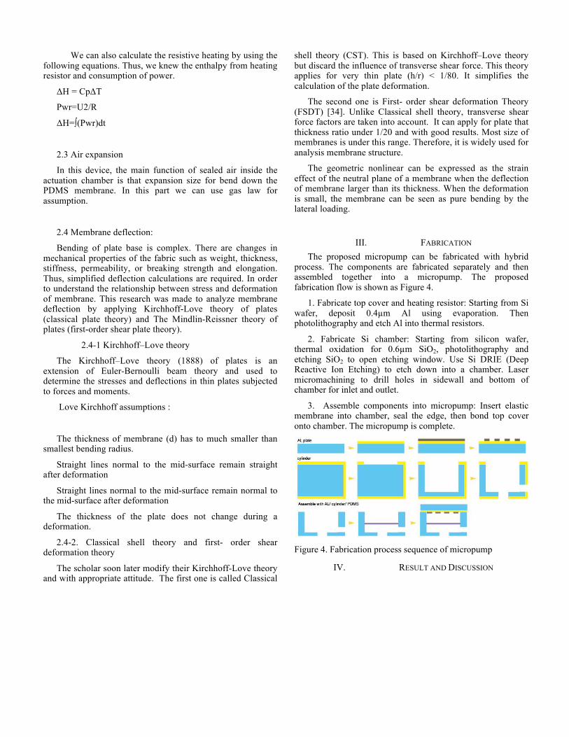
III. FABRICATION The proposed micropump can be fabricated with hybrid
process. The components are fabricated separately and then assembled together into a micropump. The proposed fabrication flow is shown as Figure 4.
1. Fabricate top cover and heating resistor: Starting from Si wafer, deposit 0.4µm Al using evaporation. Then photolithography and etch Al into thermal resistors.
2. Fabricate Si chamber: Starting from silicon wafer, thermal oxidation for 0.6µm SiO2, photolithography and etching SiO2 to open etching window. Use Si DRIE (Deep Reactive Ion Etching) to etch down into a chamber. Laser micromachining to drill holes in sidewall and bottom of chamber for inlet and outlet.
3. Assemble components into micropump: Insert elastic membrane into chamber, seal the edge, then bond top cover onto chamber. The micropump is complete.
Figure 4. Fabrication process sequence of micropump
IV. RESULT AND DISCUSSION

In simulation, we increased the pound force per square inch (psi) from 10 psi to 40 psi The maximum deflection is around 250 µm. We knew the maximum deflection, thickness of membrane, diameter of membrane, than we can get radius of curvature. Thus, according to plate theory. This experiment result is close to classical shell theory (h/r < 1/80). Next, we used software to simulate different thickness of membrane and
pressure. We found the relationship shown as table1.
Table 1 relationship between deformation and membrane thickness: When membrane getting thicker, deformation
become large. The deformation rate directly as the pressure. The most commonly method is use development solution
SU-8. The temperature change inside air chamber in response to voltage pulse is shown in table 2. As we can see, temperature first increase due to input voltage pulse. Once the voltage pulse is discontinued, the temperature drops quickly
due to heat dissipation.
Table 2 Relationship between response time and temperature
V. CONCLUSIONS In this paper, the design and analysis of a thermal actuated
MEMS micropump is proposed. The micropump utilizes air thermal expansion induced by resistor heating to pump microfluid flow. The working principle of the micropump is analyzed. Netgen simulation is used to verify the deflection of elastic membrane with Classical shell theory and first- order shear deformation theory. We found the simulation result are very close to theory. In summary, we found some points:
1. Classical shell theory just considered the straight liner force on plate. This limitation cause it can only use on small displacement calculation. Even-through the pump size is quite small, but we found the process of deflection not only contain straight force. The transverse shear force should be considered and our simulation result also proof this point. First- order shear deformation theory is more closer to real situation than classical shell theory
2. Classical shell theory is a simply way to calculation small displacement with accuracy result. But, based on our simulation result on chapter 4. We found when the membrane thickness larger than 100µm and displacement more than 20µm, the transverse shear force should be considered.
3. According to our results, the factors of deflection membrane not only contain Young's modulus, density and Poisson ratio but also considered the wide and thickness of chip or photoresist when it fabricated.. Control the spinning speed of photoresist machine can affect the space between glass substrate and PDMS (chamber wall ). Large space size means more thicker of chamber wall in scale and the deflection rate also become large, but also means more difficult for production.
These experimental results data could be provided a prototype of the design pneumatic pump. Now, everything just in computer simulation and only modified the membrane

deflection. Only concern the pump body but not included the power controller. In the future, the main job is to make this device more reliable and more reality. Moreover, the further goal is perfectly integration with biochip technology.
REFERENCES
[1] Lee, Abraham P. and Lee, L. James, " BioMEMS and Biomedical Nanotechnology Vol. 1 Biological and Biomedical Nanotechnology ", United States, 2006
[2] Peter Woias, " Micropumps—past, progress and future prospects ", Science Direct, Vol. 105, no. 1, pp. 28-38, 2005
[3] D J Laser and J G Santiago, “A review of micropumps ", Department of Mechanical Engineering, Stanford University, 2004
[4] Yi-Ning Yang, Fu-Chun Huang and Gwo-Bin Lee,”A New Pneumatic Micropump with a High Pumping Rate and a High Back Pressure,” International Conference on Advanced Manufacture (ICAM), Tainan, Taiwan, 2007
[5] Jianhua Tong, Craig A Simmons and Yu Sun, “Precision patterning of PDMS membranes and applications", Journal of Micromechanics and Micro engineering Volume 18 Number 3, 2008
[6] Lynn Khine and Julius M. Tsai, “Design Consideration of Membrane Structure for Thermal Actuated Micropump ", Advanced Materials Research, Volume 254, 2011, pp.42-45
[7] W.Y. Sim, H.J. Yoon, O.C. Jeong, S.S. Yang, A phase change type of micropump with aluminum flap valves, J. Micromech. Microeng. 13(2003) 286–294.
[8] C.H. Ahn and M.G. Allen, “Fluid Micropumps Based on Rotary Magnetic Actuators”, MEMS’s 95, 1995, pp. 408-412
[9] C.G.J. Schabmueller, M. Koch, M.E. Mokhtari, A.G.R. Evans, A. Brunnschweiler, H. Sehr, Self-aligning gas/liquid micropump, J. Micromech. Microeng. 12 (2002) 420–424.
[10] K. Junwu, Y. Zhigang, P. Taijiang, C. Guangming, W. Boda, Design and test of a high performance piezoelectric micropump for drug delivery, Sens. Actuators A: Phys. 121 (2005) 156–161.
[11] V. Lintel et al., “ Sensors and Actuators A ”, 1988, 15:p. 153-167 [12] W.L. Benard, H. Kahn, A.H. Heuer, M.A. Huff, A titanium–nickel
shapememory alloy actuated micropump, in: International Conference on Solid State Sensors and Actuators, vol. 1, 1997, pp. 361–364.
[13] W.L., Benard, et. al., “A Titanium-Nickel Shape-Memory Alloy Actuated Micropump”, Proceedings of Transducers’97, vol. 1, pp.361-364
[14] J.W. Judy, T. Tamagawa, D.L. Polla, Surface micromachined micropump, Proc. MEMS 91 (1991) 182–186.M.M. Teymoori, A.A. Sani, Design and simulation of a novel electrostatic micromachined pump for drug delivery applications, Sens. Actuators A: Phys. 117 (2005) 222–229.
[15] Zengerle, R., et al., "A Hi-Directional Silicon Micropump," Proceedings of MEMS, 1995
[16] Zhan, T. Lo, L.P. Liu, A silicon membrane micropump with integrated bimetallic actuator, Chinese J. Electron. 5 (1996) 29–35.
[17] Boehm, S., Olthuis, W., and Bergveld, P., "A Plastic Micropump Constructed with Conventional Techniques and Materials," Sens. Actuators A, Phys., vol. 77, pp. 223-228, 1999.
[18] Manz, A.; Harrison, D.J.; Fettinger, J.C.; Verpoorte, E.; Ludi, H.; Widmer, H.M.; Ciba-Geigy AG, Basel " Integrated electroosmotic pumps and flow manifolds for total chemical analysis systems", Digest of Technical Papers, TRANSDUCERS '91, pp 939-941, 1991
[19] S. Zeng, C.H. Chen, J.C. Mikkelsen, J.G. Santiago, Fabrication and characterization of electroosmotic micropumps, Sens. Actuators B: Chem. 79 (2001) 107–114.
[20] E. Stemme and G. Stemme, “A Valve-less Diffuser/Nozzle based Fluid Pump,” Sensors and Actuators, vol. A39 (1993) 159-167. E. Stemme and G. Stemme, “Valve-Less Fluid Pump,” Swedish Patent Appl. No. 9 300 604-7, 1993
[21] K.S. Yun, I.J. Cho, J.U. Bu, C.J. Kim, E. Yoon, A surface tension driven micropump for low voltage and low power operations, J. MEMS l.11 (2002) 454–461.
[22] Bruus, H., " Theoretical microfluidics" , Oxford University Press ,2007 [23] Tabeling, P,"Introduction to microfluidics" ,Oxford University Press,
2005 [24] P. Karayacoubian, M. M. Yovanovich, J. R. Culham, " Thermal
resistance-based bounds for the effective conductivity of composite thermal interface materials ", Department of mechanical engineering, University of Waterloo, Waterloo, Ontario, Canada, pp. 2006
[25] Love, A. E. H, " A Treatise on the mathematical theory of elasticity" , New York: Dover , 1944
[26] Beukema, W.; Limpers, J.; N.V.Philips'Gloeilampenfabrieken, " Resistor dimensions and power dissipation ", Materials and packaging, IEEE Transactions on, Vol.1, USA, January, 2006, pp. 149-157.
[27] Thomson, William, Lord Kelvin ," On an Absolute Thermometric Scale founded on Carnot's Theory of the Motive Power of Heat, and calculated from Regnault's Observations ", Philosophical Magazine,1998
[28] Timoshenko, S. and Woinowsky-Krieger, S., “Theory of plates and shells ", McGraw-Hill New York., 1959
[29] A. E. H. Love, " On the small free vibrations and deformations of elastic shells" , Philosophical trans. of the Royal Society (London), 1888, Vol. série A, N° 17 p. 491–549
[30] R. D. Mindlin ," Influence of rotatory inertia and shear on flexural motions of isotropic, elastic plates ", Journal of Applied Mechanics, 1951, Vol. 18 p. 31–38.
[31] Reddy, J. N., "Theory and analysis of elastic plates and shells" , CRC Press, Taylor and Francis, 2007.:
[32] A. N. Guz' "Generalized theory of shells ", plenum publishing,corporation, 1978.
[33] S. Seren Akavci " The first order shear deformation theory for symmetrically laminated plates on elastic foundations " , Department of Architecture, University of Cukurova Adana, Tyrkey, 2007.
[34] Qiuhua Li, Junghsen Lieh and A Mayer, " Large deflection of laminated circular plates with clamped edge and uniform loading", Proceedings of the Institution of Mechanical Engineers, Part E: Journal of Process Mechanical Engineering,2005
[35] Lotters, J. C.; Olthuis, W.; Veltink, P. H.; Bergveld, P. " The mechanical properties of the rubber elastic polymer polydimethylsiloxane for sensor applications " , J Micromech Microeng 7 (3): 145–147., 1997.
[36] aguirigan, A. L.; Beebe, D. J, " Integrative Biology" , pp182-195, 2009 [37] Jaeger, Richard C " Film Deposition " , Introduction to microelectronic
fabrication.“, 2002 [38] Franz Laermer and Andrea Urban, Robert Bosch Gmbh, “Milestones in
deep reactive ion etching”, Transducers’05, 13th international conference on solid state sensors, actuators, microsystems, Seoul, Korea, june 5-9, 2005, p. 1118
[39] C. Rowan," Excimer lasers drill precise holes with higher yields" , Laser Focus World, 1995
[40] Khalid Anwar, Taeheon Han, Sun Min Kim," Reversible sealing techniques for microdevice applications ", Department of mechanical engineering, inha university, 253 younghyun-dong, nam-gu, incheon, republic of Korea , 2010,pp402-751
[41] Jaeger, Richard C, “Lithography". Introduction to Microelectronic Fabrication " , Upper Saddle River: Prentice Hall, 2002
[42] Omkaram Nalamasu, May Cheng, Allen G Timko, Victor Pol, Elsa Reichmanis, Larry F Thompson "An overview of resist processing for deep-UV lithography " , AT&T bell laboratories, Murray Hill,, 1994
[43] "Chemical Specific Information — Piranha Solutions" , Laboratory Safety Manual. Princeton University.
[44] C. Di Bartolomeo, P. Barker, M. C. Petty, P. Adams, A. P. Monkman, " A photolithographic technique for patterning spin-coated polyaniline films ", Advanced Materials for Optics and Electronics, Volume 2, Issue 5, 2004pages 233–236

[45] C. Rowan," Excimer lasers drill precise holes with higher yields”, Boca Raton, Florida: CRC Press. pp. 9, 2002
[46] V.G.Kutchoukov et al., “New photoresist coating method for 3-D structured wafers”, Sensor & Actuator A85, 2000, pp 377-383.
[47] P.Kersten et al., S.Bowstra, J.W.Petersen, “Photolithography on micromachined 3D surfaces using electrodeposited photoresists”, Sensors and actuators , 1995,pp 51-54
[48] Hsu, Jyh-Ping; Lin, Sung-Hwa; Chen, Wen-Chang; Tseng, Shiojenn, " Mathematical analysis of soft baking in photolithography ", Department of chemical engineering, national Taiwan university, Taipei, Taiwan, 2009
[49] John A. Yasaitis, Mary Ann Perez-Maher, Jean Michel Karam, " Thick SU-8 photolithography for BioMEMS micromachining and microfabrication Process Technology”, VIII, 2003