ASE 8 - Engine Performancefaculty.ccbcmd.edu/~smacadof/Books/A8StudentWorkBooks161/SWB… · EGR...
48
ASE 8 - Engine Performance Module 14 On-Board Diagnostics II Student Exercises
Transcript of ASE 8 - Engine Performancefaculty.ccbcmd.edu/~smacadof/Books/A8StudentWorkBooks161/SWB… · EGR...

ASE 8 - Engine Performance
Module 14On-Board Diagnostics II
Student Exercises
ContentsSystem Overview ............................................................................................. 3
Overview Worksheet ........................................................................................................ 3
Scan Tool Diagnostics ..................................................................................... 5Tech 2 Overview Worksheet ............................................................................................. 5Tech 2 Usage Worksheet ................................................................................................. 6
Sensor Diagnostics........................................................................................ 11Overview Worksheet ...................................................................................................... 11ECT Sensor Diagnostics Worksheet ............................................................................. 12MAF Sensor Diagnostics Worksheet ............................................................................. 14CMP Sensor Diagnostics Worksheet............................................................................. 17TP Sensor Diagnostics Worksheet ................................................................................ 20
HO2S and Catalyst Diagnostics ....................................................................22Overview Worksheet ...................................................................................................... 22HO2S Heater Diagnostics Worksheet ............................................................................ 23Post-Converter HO2S Heater Diagnostics Worksheet ................................................... 25Catalyst Efficiency Diagnostic Worksheet ...................................................................... 28Misfire Detection Diagnostics ........................................................................................ 30Overview Worksheet ...................................................................................................... 30Misfire Detection Diagnostic Worksheet ........................................................................ 31
Control System Diagnostics ..........................................................................33Overview Worksheet ...................................................................................................... 33EGR System Diagnostics Worksheet (On-Vehicle) ........................................................ 34EGR System Diagnostics Worksheet (At-Desk) ............................................................. 36
EVAP System Diagnostics ............................................................................37Overview Worksheet ...................................................................................................... 37EVAP System Diagnostics Worksheet – Non Enhanced (On-Vehicle) ............................ 38EVAP System Diagnostics Worksheet – Non Enhanced (At Desk) ................................ 40Enhanced EVAP System Diagnostics Worksheet – (On-Vehicle) ................................... 42Enhanced EVAP System Diagnostics Worksheet – (At-Desk) ....................................... 44
Reprogramming .............................................................................................46Service Programming System (SPS) ............................................................................. 46Task List ........................................................................................................................ 48OBD II Performance Task List ........................................................................................ 48
© 2002 General Motors CorporationAll Rights Reserved
ASE 8 - EnginePerformance
Module 14 -On-BoardDiagnostics II
14-3
Student ExercisesSystem OverviewOverview WorksheetDirections: Read chapter 1 of the OBD II Student Workbook and answerthe following questions. Also include the page number where the answer wasfound.
1. OBD II requires that the on-board computer monitors and activelyperforms diagnostic tests on _______________ ________________systems. Page ___________
2. What type of Serial Data does GM use for OBD II systems?______________________________________ Page ___________
3. What is the difference between UART and Class 2 serial data?
Page ___________
4. What are the two management systems of the PCM?______________________________________ Page ___________
5. What types of diagnostic tests does the PCM perform?
Page ___________
6. What is the definition of a trip in relation to OBD II?______________________________________ Page ___________
© 2002 General Motors CorporationAll Rights Reserved
ASE 8 - EnginePerformance
Module 14 -On-BoardDiagnostics II
14-4
Student ExercisesOverview Worksheet (continued)
7. What are the parameters of a warm-up cycle?______________________________________ Page ___________
8. What information does the Diagnostic Executive store?_________________ ________________ ___________________________________ _________________________________ ________________ Page ___________
9. What are the TEST FAIL actions of the Diagnostic Management System?_________________ ________________ ___________________________________ _________________________________ ________________ Page ___________
10.What types of DTCs illuminate the MIL?______________________________________ Page ___________
11. With a type B DTC, how many trips with a failure are required to turn onthe MIL?______________________________________ Page ___________
12.Freeze Frame data contains only certain data parameters, not all theparameters found on the engine data list. T or F

© 2002 General Motors CorporationAll Rights Reserved
ASE 8 - EnginePerformance
Module 14 -On-BoardDiagnostics II
14-5
Student ExercisesScan Tool DiagnosticsTech 2 Overview WorksheetDirections: Follow the steps below and answer the questions. Use serviceinformation and the Tech 2 as resources when needed.
1. The Tech 1 requires a Vehicle Interface Module (VIM) to communicatewith an OBD II complaint vehicle. Does the Tech 2 require the use of aVIM for OBD II communications?
Yes or No
2. What piece of equipment is necessary to program the PCM if it is notinstalled in the vehicle?______________________________________ Page ___________
3. When in a Tech 2 data list, what soft key can be pressed to quickly moveto the next data list?______________________________________ Page ___________
4. What information will the Tech 2 store by using CAPTURE INFO?
Page ___________
5. When in SYSTEM INFORMATION, what do the IM FLAGS indicate?
Page ___________
© 2002 General Motors CorporationAll Rights Reserved
ASE 8 - EnginePerformance
Module 14 -On-BoardDiagnostics II
14-6
Student ExercisesTech 2 Usage WorksheetObjectives: At the end of this exercise, you will be able to:• Describe the additional information available on OBD II systems when
using the Tech 2.• Locate specific Tech 2 menus.
Directions: Build the vehicle using Tech 2 pick lists, then use Tech 2 to fill inthe blanks under each of the menu items listed on the following pages. Ifthere is not an option for one of the F-keys, write NA in the blank.
Vehicle:Make: ______ Model: _______ Model Year: ______ Engine: ______
Enter F0: Diagnostic Trouble Codes (DTC)List the selections available:
F0: ___________________________________F1: ___________________________________F2: ___________________________________F3: ___________________________________F4: ___________________________________F5: ___________________________________F6: ___________________________________F7: ___________________________________F8: ___________________________________F9: ___________________________________
© 2002 General Motors CorporationAll Rights Reserved
ASE 8 - EnginePerformance
Module 14 -On-BoardDiagnostics II
14-7
Student Exercises
List the F-key. F _______: DTC InformationSelect this option and list the selections available:
F0: ___________________________________F1: ___________________________________F2: ___________________________________F3: ___________________________________F4: ___________________________________F5: ___________________________________F6: ___________________________________F7: ___________________________________F8: ___________________________________F9: ___________________________________
Press Exit Twice
Enter F1: Data DisplayList the selections available:
F0: ___________________________________F1: ___________________________________F2: ___________________________________F3: ___________________________________F4: ___________________________________
Tech 2 Usage Worksheet (continued)
© 2002 General Motors CorporationAll Rights Reserved
ASE 8 - EnginePerformance
Module 14 -On-BoardDiagnostics II
14-8
Student ExercisesTech 2 Usage Worksheet (continued)Enter F0: Engine Data DisplayList the selections available:
F0: ___________________________________F1: ___________________________________F2: ___________________________________F3: ___________________________________F4: ___________________________________F5: ___________________________________F6: ___________________________________
Press Exit Twice
Enter F2: Special FunctionsList the selections available:
F0: ___________________________________F1: ___________________________________F2: ___________________________________F3: ___________________________________F4: ___________________________________F5: ___________________________________
List the F-key F _____: Engine Output ControlsSelect this option and list the FIRST and LAST selections available:
First Selection: __________________________Last Selection: __________________________
Press Exit Once
© 2002 General Motors CorporationAll Rights Reserved
ASE 8 - EnginePerformance
Module 14 -On-BoardDiagnostics II
14-9
Student ExercisesTech 2 Usage Worksheet (continued)List the F-key. F _______: Fuel SystemSelect this option and list the selections available:
F0: ___________________________________F1: ___________________________________F2: ___________________________________F3: ___________________________________F4: ___________________________________F5: ___________________________________
Press Exit Twice
Enter F3: SnapshotList the selections available:
F0: ___________________________________F1: ___________________________________F2: ___________________________________F3: ___________________________________
Enter F0: Engine SnapshotList the selections available:Trigger Type
F0: ___________________________________F1: ___________________________________F2: ___________________________________
Trigger PointF4: ___________________________________F5: ___________________________________F6: ___________________________________F7: ___________________________________
F8: ___________________________________F9: ___________________________________
Press Exit Twice

© 2002 General Motors CorporationAll Rights Reserved
ASE 8 - EnginePerformance
Module 14 -On-BoardDiagnostics II
14-10
Student ExercisesTech 2 Usage Worksheet (continued)Enter F4: System InformationList the requested information in the blank below. The ignition mustbe on to complete this exercise:Note: some info may not be available
Emission Related DTC(s):Number of DTC(s): ____________________________MIL Requested: ____________________________
Test Completed (Y or N)Catalyst: ____________________________EVAP ____________________________HO2S: ____________________________HO2S Heater: ____________________________EGR System: ____________________________Press Exit Once
Enter F5: ID InformationList the selections available
F0: ___________________________________F1: ___________________________________F2: ___________________________________F3: ___________________________________F4: ___________________________________F5: ___________________________________
Disconnect the Tech 2 from the vehicle

© 2002 General Motors CorporationAll Rights Reserved
ASE 8 - EnginePerformance
Module 14 -On-BoardDiagnostics II
14-11
Student ExercisesSensor DiagnosticsOverview WorksheetDirections: Read chapter 3 of the OBD II Student Workbook and answerthe following questions. Also include the page number where the answer wasfound.
1. Input components are monitored for __________ and ___________ .Page ___________
2. How does the PCM determine if the ECT sensor is out of range?______________________________________ Page ___________
3. The PCM uses MAP input for which diagnostic(s)?______________________________________ Page ___________
4. What sensor(s) input does the PCM use to determine if the TP sensor isdeteriorated?______________________________________ Page ___________
5. How dos the PCM determine if the MAP sensor has failed systemperformance?______________________________________ Page ___________
© 2002 General Motors CorporationAll Rights Reserved
ASE 8 - EnginePerformance
Module 14 -On-BoardDiagnostics II
14-12
Student ExercisesECT Sensor Diagnostics WorksheetObjectives: At the end of this exercise, you will be able to:• Refer to service manual information for a DTC.• Monitor the ECT sensor, using Tech 2.• Define the term warm-up cycle.
Directions: Follow the steps below and answer the questions. Use serviceinformation as a resource when needed.
1. At the bench, refer to the diagnostic information for DTC P0125.What are the conditions necessary for the control module to set thisDTC?_________________ _________________ ________________________________ _________________ ________________________________ _________________ _______________
2. What action does the control module take when this DTC is set?________________________________________________________________________________________________________________
3. According to the service manual, could a faulty thermostat cause DTCP0125 to set? Y or NWhy or why not? ___________________________________________
4. Refer to DTC P0125 diagnostic information. What conditions will causethe control module to turn OFF the MIL?________________________________________________________________________________________________________________

© 2002 General Motors CorporationAll Rights Reserved
ASE 8 - EnginePerformance
Module 14 -On-BoardDiagnostics II
14-13
Student ExercisesECT Sensor Diagnostics Worksheet (continued)5. What conditions will cause the control module to clear DTC P0125?
________________________________________________________________________________________________________________
6. What is a warm-up cycle?________________________________________________________________________________________________________________
7. Starting with the engine at ambient temperature, record the followinginformation about the classroom vehicle:What is the ECT sensor temperature and/or voltageindication at KEY-ON? ____________________________________What is the IAT sensor temperature and/or voltageindication at KEY-ON? ____________________________________
8. Set up the Tech 2 to monitor ECT, Loop Status, and Engine Run Time.Start the engine and allow it to idle. Record Engine Coolant Temperature(in degrees Celsius), Loop status, Warm-up Cycle status, and Thermostatstatus each minute in the following chart:
9. Referring to the chart in question eight, was a Warm-up Cyclecompleted? Y or NDoes the engine need to be at operating temperature (thermostat open)to complete a Warm-up Cycle? Y or N
Start (0 Min) 1 Min 2 Min 3 Min 4 Min
Open/Closed Loop
W/U Cycle (Y or N)
T'stat. Open (Y or N)
ECT

© 2002 General Motors CorporationAll Rights Reserved
ASE 8 - EnginePerformance
Module 14 -On-BoardDiagnostics II
14-14
Student ExercisesMAF Sensor Diagnostics WorksheetObjectives: At the end of this exercise, you will be able to:• Perform the OBD System Check procedures.• View and interpret DTC Information.• View and record Fail Record information.• Defer a Trip.
Directions: Follow the steps below and answer the questions. Use serviceinformation as a resource when needed.• To begin this exercise, all information should be cleared from the PCM.
Use Tech 2 to Clear DTC Information.• Start the engine and run it at 1000 RPM. Remove the MAF sensor
electrical connector to set a DTC for the MAF sensor. Turn the ignitionswitch to OFF.
• Perform the OBD System Check and answer questions 1 and 2 beforegoing on to any other diagnostic charts.
1. Checking for DTC Information is part of the OBD System Check. Recordany DTCs for the following:What History DTCs exist?____________________________________What DTCs have failed this ignition cycle? _______________________What DTCs have failed the last test? ___________________________
Did you save the freeze frame and fail record information? If not, do itnow by using the Capture Info feature on the Tech 2.
2. Based on the OBD System Check results, what is your next step?________________________________________________________
3. Proceed to the diagnostic chart for the DTC related to the MAF sensor.What is the first “specified value” for the MAP sensor signal listed in thediagnostic chart? _________________Reconnect the MAF sensor connector.

© 2002 General Motors CorporationAll Rights Reserved
ASE 8 - EnginePerformance
Module 14 -On-BoardDiagnostics II
14-15
Student ExercisesMAF Sensor Diagnostics Worksheet (continued)4. Start the engine and locate the MAF sensor signal on a live data list.
Record the MAF sensor signal at idle and at 2500 RPM.Idle _____________ 2500 RPM __________
5. Turn the ignition off for 15 seconds to let the PCM to power down. ReviewFail Record information for the MAF sensor using the Tech 2. Fill in thefollowing information:
Note: Some vehicles may not have all parameters available.
DTC number _____________ TP angle _______________________MAF sensor ______________ Miles since 1st fail ________________ECT sensor ______________ Miles since last fail ________________Engine load ______________ Fail counter _____________________Engine speed ____________ Pass counter ____________________MAP sensor ______________ Not run counter___________________
6. How can this information be used? _____________________________________________________________________________________________________________________________________________________________________________________________________________________________________________________________
7. Return to the DTC Applications menu. Select F1: Specific DTC and theenter the DTC from question number five. Check ( ) the informationthat exists for the DTC you have entered:___ Last test failed ___ Test ran and passed___ Failed this ignition ___ History___ Test failed since code cleared ___ Not run this ignition___ MIL SVS or message requested ___ Not run SCC___ Last test passed
4
© 2002 General Motors CorporationAll Rights Reserved
ASE 8 - EnginePerformance
Module 14 -On-BoardDiagnostics II
14-16
Student ExercisesMAF Sensor Diagnostics Worksheet (continued)8. What can be determined by reviewing this information? _____________
________________________________________________________
9. Answer the following questions based on the information in question #7.Did the DTC fail during this ignition cycle? Y or NDid the DTC pass this ignition cycle? Y or NHow was this determined? ___________________________________
10.What are the conditions for the diagnostic to run and fail?Engine Speed _________ TP angle ___________________Ignition Voltage _________ Other _______________________________ MAF Frequency __________________________
11. Start and run the engine.Has the control module diagnostic test for the MAF sensor run during thisignition cycle? Y or NWhat indicates this? _______________________________________
12. Is the MIL still ON? Y or NWhy or why not? __________________________________________
13. If the MIL is still ON, turn the ignition switch to OFF until the control moduleends communication with the Tech 2. Start and run the engine.Has the control module turned OFF the MIL during this ignition cycle?
Y or NWhy or why not? __________________________________________
14.Define what a trip is for this DTC: ______________________________________________________________________________________
(Do not clear information)
© 2002 General Motors CorporationAll Rights Reserved
ASE 8 - EnginePerformance
Module 14 -On-BoardDiagnostics II
14-17
Student ExercisesCMP Sensor Diagnostics Worksheet(use only if the classroom vehicle is not equipped with a MAF sensor)
Objectives: At the end of this exercise, you will be able to:• Perform the OBD System Check procedures.• View and interpret DTC Information.• View and record Fail Record information.• Defer a Trip.
Directions: Follow the steps below and answer the questions. Use serviceinformation as a resource when needed.• To begin this exercise, all information should be cleared from the PCM.
Use Tech 2 to Clear DTC Information.• Remove the CMP sensor electrical connector, then start the engine.
When a CMP DTC sets, turn the ignition switch to OFF.• Perform the OBD System Check and answer questions 1 and 2 before
going on to any other diagnostic charts.
1. Checking for DTC Information is part of the OBD System Check. Recordany DTCs for the following:What History DTCs exist?____________________________________What DTCs have failed this ignition cycle? _______________________What DTCs have failed the last test? ___________________________Did you save the freeze frame and fail record information? If not, do itnow by using the Capture Info feature on the Tech 2.
2. Based on the OBD System Check results, what is your next step?________________________________________________________

© 2002 General Motors CorporationAll Rights Reserved
ASE 8 - EnginePerformance
Module 14 -On-BoardDiagnostics II
14-18
Student ExercisesCMP Sensor Diagnostics Worksheet (continued)3. Proceed to the diagnostic chart for the DTC related to the CMP sensor.
Start the engine and locate CMP sensor signal on a live data list. Is thecounter incriminating? Y or NStop the engine and reconnect the CMP sensor connector.
4. Start the engine and locate the CMP sensor signal on a live data list.Describe the CMP sensor signal at idle: ________________________
5. Stop the engine and wait 15 seconds for the PCM to power down.Review Fail Record information for the CMP sensor using the Tech 2. Fillin the following information below:
Note: Some vehicles may not have all parameters available.DTC number _____________ TP angle _______________________MAF sensor ______________ Miles since 1st fail ________________ECT sensor ______________ Miles since last fail ________________Engine load ______________ Fail counter _____________________Engine speed ____________ Pass counter ____________________MAP sensor ______________ Not run counter___________________
6. How can Fail Record Data information be used in diagnostics? _______________________________________________________________________________________________________________________________________________________________________________________________________________________________________
7. Return to the DTC Applications menu. Select F1: Specific DTC and thenenter the DTC from question number five. Check ( ) the informationthat exists for the DTC you have entered:___ Last test failed ___ Test ran and passed___ Failed this ignition ___ History___ Failed SCC ___ Not run this ignition___ MIL SVS or message requested ___ Not run SCC___ Last test passed
4
© 2002 General Motors CorporationAll Rights Reserved
ASE 8 - EnginePerformance
Module 14 -On-BoardDiagnostics II
14-19
Student ExercisesCMP Sensor Diagnostics Worksheet (continued)8. What can be determined by reviewing this information? _____________
________________________________________________________
9. Answer the following questions based on the information in question #7.Did the DTC fail during this ignition cycle? Y or NDid the DTC pass this ignition cycle? Y or NHow was this determined? ___________________________________
10.What are the conditions for the diagnostic to run and fail?________________________________________________________________________________________________________________________________________________________________________
11. Start and run the engine.Has the control module diagnostic test for the CMP sensor run during thisignition cycle? Y or NWhat indicates this? _______________________________________
12. Is the MIL still ON? Y or NWhy or why not? __________________________________________
13. If the MIL is still ON, turn the ignition switch to OFF until the control moduleends communication with the Tech 2. Start and run the engine.Has the control module turned OFF the MIL during this ignition cycle?
Y or NWhy or why not? __________________________________________
14.Define what a trip is for this DTC: ______________________________________________________________________________________
(Do not clear information)

© 2002 General Motors CorporationAll Rights Reserved
ASE 8 - EnginePerformance
Module 14 -On-BoardDiagnostics II
14-20
Student ExercisesTP Sensor Diagnostics WorksheetObjectives: At the end of this exercise, you will be able to:• Perform the OBD System Check procedures.• Use the Tech 2 to view different types of DTC Information.• View and record Fail Record information.• Interpret the difference between Fail Record and Freeze Frame
information.
Directions: Follow the steps below and answer the questions. Use serviceinformation as a resource when needed.1. Set a DTC related to the TP sensor by turning the ignition switch to RUN
and removing the TP sensor electrical connector. Start the engine andwhen the MIL illuminates, install the connector. Turn the ignition switch toOFF.
2. Begin by performing the OBD System Check following the servicemanual procedures and answer the following questions:Is the MIL turned ON? Y or NDoes the scan tool display data? Y or NDoes the engine start and run? Y or N
3. Start the engine. With the Tech 2 on the first Application menu, selectF0: DTC and then select F0: DTC Information. List any DTCs stored inthe F2: Last Test Failed menu:________________________________________________________
4. Based on the OBD System Check results, what is your next step?________________________________________________________
5. With the Tech 2 on the DTC Applications Menu, select F4: Capture Infoand then select F0: Store Info (if the Tech 2 already has capturedinformation, it will display Refresh Info).

© 2002 General Motors CorporationAll Rights Reserved
ASE 8 - EnginePerformance
Module 14 -On-BoardDiagnostics II
14-21
Student ExercisesTP Sensor Diagnostics Worksheet (continued)6. Refer to the diagnostic procedures for the DTC related to the TP sensor.
What is the first “specified value” for the TP sensor signal in thediagnostic chart?Record the actual TP sensor voltage from a live data list.
7. Record the Captured Info Fail Record information for DTC P0122:
Note: Some vehicles may not have all parameters available.
MAF sensor ________________ Fail counter __________________Engine load ________________ Pass counter _________________Engine speed ______________ Not run counter ________________TP angle __________________
8. Review the Captured Info Freeze Frame information.Is it the same as the Fail Record information for the TP sensor DTC?Y or NWhy or why not? ___________________________________________
9. Turn the Ignition off for 15 seconds, then start the vehicle. With the Tech 2on the first Applications Menu, select F0: DTC and then select F5:Diagnostic Tests Status. Is DTC P0122 on the list? Y or NWhy or why not? ___________________________________________
10.Remove the TP sensor electrical connector.Is DTC P0122 on the list now? Y or NWhat is the status of DTC P0122? Ran? ____ Fail? _____
Turn the ignition off and reconnect the TP sensor connector.
© 2002 General Motors CorporationAll Rights Reserved
ASE 8 - EnginePerformance
Module 14 -On-BoardDiagnostics II
14-22
Student ExercisesHO2S and Catalyst DiagnosticsOverview WorksheetDirections: Read the related section of the OBD II Student Workbook andanswer the following questions. Also include the page number where theanswer was found.1. Why are Heated Oxygen Sensors being used instead of unheated
Oxygen Sensors?______________________________________ Page ___________
2. HO2S 1 Bank 2 indicates which oxygen sensor location?______________________________________ Page ___________
3. What are the OBD II requirements for monitoring Heated Oxygen Sensoroperation?______________________________________ Page ___________
4. What oxygen sensor function does Response Time test monitor?______________________________________ Page ___________
5. What oxygen sensor function does Time To Activity test monitor?______________________________________ Page ___________
6. What components does the PCM use to determine the efficiency of thecatalyst?______________________________________ Page ___________
7. What type of voltage output signal should the post-converter HO2S have ifthe catalyst is good??______________________________________ Page ___________
8. The voltage of the post converter HO2S is different than the pre-converterHO2S if the converter is good. Explain why.______________________________________ Page ___________
9. Catalyst damage that could cause a DTC to set can be caused by:______________________________________ Page ___________
© 2002 General Motors CorporationAll Rights Reserved
ASE 8 - EnginePerformance
Module 14 -On-BoardDiagnostics II
14-23
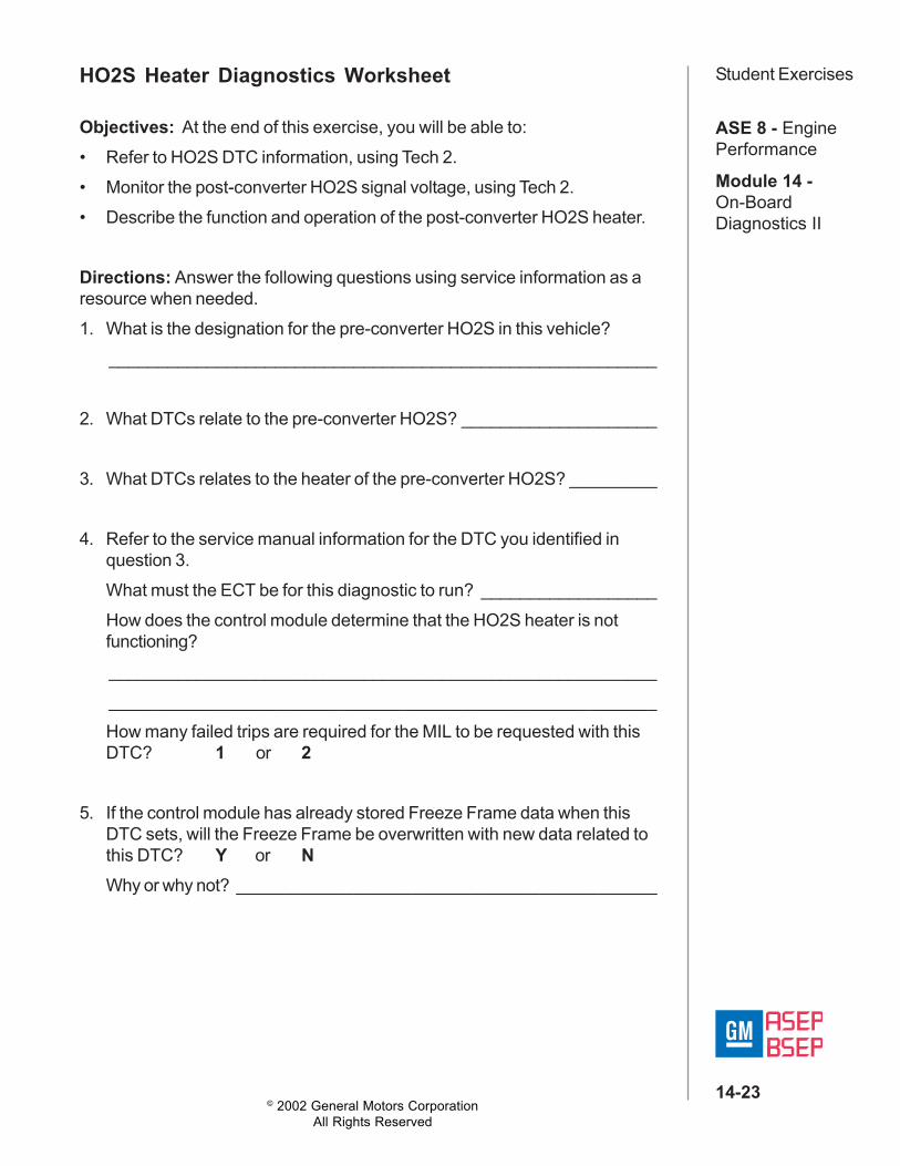
Student ExercisesHO2S Heater Diagnostics Worksheet
Objectives: At the end of this exercise, you will be able to:• Refer to HO2S DTC information, using Tech 2.• Monitor the post-converter HO2S signal voltage, using Tech 2.• Describe the function and operation of the post-converter HO2S heater.
Directions: Answer the following questions using service information as aresource when needed.1. What is the designation for the pre-converter HO2S in this vehicle?
________________________________________________________
2. What DTCs relate to the pre-converter HO2S? ____________________
3. What DTCs relates to the heater of the pre-converter HO2S? _________
4. Refer to the service manual information for the DTC you identified inquestion 3.What must the ECT be for this diagnostic to run? __________________How does the control module determine that the HO2S heater is notfunctioning?________________________________________________________________________________________________________________How many failed trips are required for the MIL to be requested with thisDTC? 1 or 2
5. If the control module has already stored Freeze Frame data when thisDTC sets, will the Freeze Frame be overwritten with new data related tothis DTC? Y or NWhy or why not? ___________________________________________
© 2002 General Motors CorporationAll Rights Reserved
ASE 8 - EnginePerformance
Module 14 -On-BoardDiagnostics II
14-24
Student ExercisesHO2S Heater Diagnostics Worksheet (continued)6. Refer to the HO2S heater DTC diagnostic chart.
What is the “specified value?” _________________________________
7. What faults would cause this DTC to set?_________________ _________________ ___________________________________ _________________ ___________________________________ _________________ __________________
8. Turn the ignition switch to RUN (engine OFF) and monitor the signal of aHO2S.What is the HO2S signal voltage indication...after 30 seconds: ____________ after 90 seconds: ______________after 60 seconds: ____________ after 120 seconds: _____________
Turn the ignition switch to OFF.

© 2002 General Motors CorporationAll Rights Reserved
ASE 8 - EnginePerformance
Module 14 -On-BoardDiagnostics II
14-25
Student ExercisesPost-Converter HO2S Heater Diagnostics Worksheet
Objectives: At the end of this exercise, you will be able to:• Monitor the pre-converter HO2S and post-converter HO2S, using
TECH 2.• Compare the function and operation of the pre-converter HO2S and post-
converter HO2S.
Directions: Follow the steps below and answer the questions. Use serviceinformation as a resource when needed.
1. Set the TECH 2 in the engine snapshot mode and select F4: Beginning.Select F8: Record Snapshot and then select the data list that containsHO2S data. Start the vehicle. Observe HO2S activity while allowing theengine to reach operating temperature. Do not trigger the snapshotyet.
2. Is the HO2S voltage fluctuation activity during warm-up for the pre- andpost-converter sensors similar?Y or NWhy? ___________________________________________________
3. Bring the engine speed up to 2,500 RPM for 2.5 minutes. Reduce RPMto 2000 and wait for the post-converter HO2S signal to stabilize, thentrigger the snapshot. Allow the snapshot to record for 20 seconds, thenpress the exit key to stop the snapshot.
© 2002 General Motors CorporationAll Rights Reserved
ASE 8 - EnginePerformance
Module 14 -On-BoardDiagnostics II
14-26
Student ExercisesPost-Converter HO2S Heater Diagnostics Worksheet(continued)
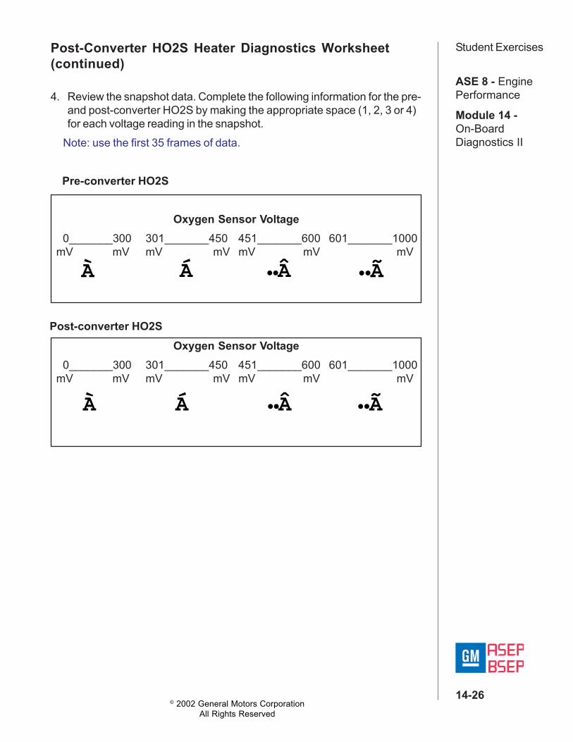
4. Review the snapshot data. Complete the following information for the pre-and post-converter HO2S by making the appropriate space (1, 2, 3 or 4)for each voltage reading in the snapshot.
Note: use the first 35 frames of data.
Pre-converter HO2S
Oxygen Sensor Voltage 0_______300 301_______450 451_______600 601_______1000 mV mV mV mV mV mV mV
À Á ••Â
Post-converter HO2S
À Á ••Â ••Ã
Oxygen Sensor Voltage 0_______300 301_______450 451_______600 601_______1000 mV mV mV mV mV mV mV
••Ã
© 2002 General Motors CorporationAll Rights Reserved
ASE 8 - EnginePerformance
Module 14 -On-BoardDiagnostics II
14-27
Student ExercisesPost-Converter HO2S Heater Diagnostics Worksheet(continued)5. Based on the voltage signal activity, is the pre-converter HO2S working
correctly?Y or N
What does this indicate about the performance of the engine?________________________________________________________________________________________________________________
6. Based on the voltage signal activity of the post-converter HO2S, is itworking correctly?
Y or NWhat does this indicate about the performance of the catalytic converter?________________________________________________________________________________________________________________
7. If the activity of the post-converter HO2S is similar to the activity of thepre-converter HO2S, what is indicated? _________________________________________________________________________________________________________________________________________

© 2002 General Motors CorporationAll Rights Reserved
ASE 8 - EnginePerformance
Module 14 -On-BoardDiagnostics II
14-28
Student ExercisesCatalyst Efficiency Diagnostic WorksheetObjectives: At the end of this exercise, you will be able to:• Refer to service manual related to catalyst efficiency.• Describe the repair verification procedure for a catalyst efficiency fault.
Directions: Answer the following questions using service information as aresource when needed.
1. List the following conditions necessary for the control module to set aDTC P0420:Intake Air Temperature: ______________________________________Engine Coolant Temperature: _________________________________Mass Air Flow: ____________________________________________RPM: ___________________________________________________Time: ___________________________________________________
2. What action does the control module take when DTC P0420 is set?_________________ _________________ ___________________________________ _________________ ___________________________________ _________________ __________________
3. What conditions are required for the control module to clear DTC P0420?_________________ _________________ ___________________________________ _________________ ___________________________________ _________________ __________________
© 2002 General Motors CorporationAll Rights Reserved
ASE 8 - EnginePerformance
Module 14 -On-BoardDiagnostics II
14-29
Student ExercisesCatalyst Efficiency Diagnostic Worksheet (continued)4. What components or systems do you check as part of DTC P0420
procedures?_________________ _________________ ___________________________________ _________________ ___________________________________ _________________ __________________
5. What Tech 2 information could you monitor to verify the repair?________________________________________________________
6. Why do you operate the vehicle for several minutes during the monitoringprocess?________________________________________________________

© 2002 General Motors CorporationAll Rights Reserved
ASE 8 - EnginePerformance
Module 14 -On-BoardDiagnostics II
14-30
Student ExercisesMisfire Detection DiagnosticsOverview WorksheetDirections: Read the related section of the OBD II Student Workbook andanswer the following questions. Also include the page number where theanswer was found.1. What sensors are used by the PCM to monitor misfire?
______________________________________ Page ___________
2. What two levels of misfire detection are required by OBD II?______________________________________ Page ___________
3. What action does the PCM take if misfire is catalyst damaging?______________________________________ Page ___________
4. How many previous crankshaft revolutions are stored in the PCMmemory?______________________________________ Page ___________
5. Under what conditions will the MIL illuminate if a misfire occurs during a2nd nonconsecutive trip?______________________________________ Page ___________
6. What condition can cause the PCM to falsely detect a misfire?______________________________________ Page ___________
7. What methods are used to identify false misfires?______________________________________ Page ___________
8. What is the function of the history misfire counters?______________________________________ Page ___________

© 2002 General Motors CorporationAll Rights Reserved
ASE 8 - EnginePerformance
Module 14 -On-BoardDiagnostics II
14-31
Student ExercisesMisfire Detection Diagnostic WorksheetObjectives: At the end of this exercise, you will be able to:• Refer to service manual related to misfire detection.• Perform the repair verification procedure for a misfire detection fault.
Directions: Answer the following questions based on data provided by theinstructor. Use service information as a resource when needed.
1. Review DTCs listed in Freeze Frame and Fail Records.Freeze Frame: ____________
Fail Records: ____________ _______________________ ___________
2. Allow the instructor to cause a misfire. While the misfire is occurring,monitor the misfire counters. Which cylinder is misfiring?________________________________________________________
3. Power down control module. Key on engine off, review DTCs listed inFreeze Frame and Fail Records:Freeze Frame: ____________
Fail Records: ____________ _______________________ _______________________ ___________
4. If a vehicle is brought to you with a DTC P0300 set in memory, and nomisfire currently present, what scan tool information could be used todetermine which cylinder(s) were at fault?________________________________________________________
5. Review misfire history counters. Which cylinder(s) indicates misfireactivity?________________________________________________________
© 2002 General Motors CorporationAll Rights Reserved
ASE 8 - EnginePerformance
Module 14 -On-BoardDiagnostics II
14-32
Student ExercisesMisfire Detection Diagnostic Worksheet (continued)6. If a vehicle is brought to you with a misfire concern but without a DTC
P0300 set in memory, and no misfire currently present, what scan tooloption could be used to determine which cylinder(s) are at fault?________________________________________________________________________________________________________________
7. Program scan tool to snapshot misfire data list. Allow instructor to causean intermittent misfire. While the intermittent misfire is occurring, triggerthe snapshot. When the snapshot is complete, review the capturedmisfire data. Which cylinder(s) was misfiring, and what indicates this?________________________________________________________________________________________________________________
8. What action does the control module take when a non-catalyst damagingDTC P0300 is set?________________________________________________________
© 2002 General Motors CorporationAll Rights Reserved
ASE 8 - EnginePerformance
Module 14 -On-BoardDiagnostics II
14-33
Student ExercisesControl System DiagnosticsOverview WorksheetDirections: Read the related section of the OBD II Student Workbook andanswer the following questions. Also include the page number where theanswer was found.
1. The Idle Control Monitoring Diagnostic includes what types of testing?______________________________________ Page ___________
2. The intrusive test for the IAC diagnostic occurs under what drivingconditions?______________________________________ Page ___________
3. OBD II requires that ________________________________ term fueltrim is monitored. Page ___________
4. How does the introduction of exhaust gases into the cylinder impactemissions?______________________________________ Page ___________
5. What affect does exhaust gas recirculation have on intake manifoldpressure?______________________________________ Page ___________
6. The intrusive test for the EGR Diagnostic commands the valve on duringdeceleration. What affect will this have on engine RMP?______________________________________ Page ___________
7. The PCM monitors the ______________________ sensor during theAIR system diagnostics.______________________________________ Page ___________
8. How many trips with an AIR failure are required to illuminate the MIL?______________________________________ Page ___________
© 2002 General Motors CorporationAll Rights Reserved
ASE 8 - EnginePerformance
Module 14 -On-BoardDiagnostics II
14-34
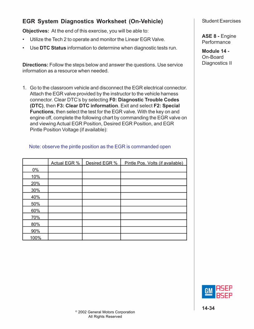
Student ExercisesEGR System Diagnostics Worksheet (On-Vehicle)Objectives: At the end of this exercise, you will be able to:• Utilize the Tech 2 to operate and monitor the Linear EGR Valve.• Use DTC Status information to determine when diagnostic tests run.
Directions: Follow the steps below and answer the questions. Use serviceinformation as a resource when needed.
1. Go to the classroom vehicle and disconnect the EGR electrical connector.Attach the EGR valve provided by the instructor to the vehicle harnessconnector. Clear DTC’s by selecting F0: Diagnostic Trouble Codes(DTC), then F3: Clear DTC information. Exit and select F2: SpecialFunctions, then select the test for the EGR valve. With the key on andengine off, complete the following chart by commanding the EGR valve onand viewing Actual EGR Position, Desired EGR Position, and EGRPintle Position Voltage (if available):
Note: observe the pintle position as the EGR is commanded open
Actual EGR % Desired EGR % Pintle Pos. Volts (if available)0%10%20%30%40%50%60%70%80%90%
100%
© 2002 General Motors CorporationAll Rights Reserved
ASE 8 - EnginePerformance
Module 14 -On-BoardDiagnostics II
14-35
Student ExercisesEGR System Diagnostics Worksheet (On-Vehicle)(continued)2. Disconnect the EGR connector and run the engine until an EGR DTC
sets. From the first Application Menu of the Tech 2 select F0: DTC, thenselect F5: Diagnostic Test Status. Has an EGR diagnostics test ran andfailed? Y or NHow was this determined? __________________________________
3. Exit from Diagnostic Test Status and select F1: Specific DTC. Enter theDTC from question number two and check ( ) the information thatexists for the DTC related to the EGR:___ Last test failed ___ Test ran and passed___ Failed this ignition ___ Passed this ignition___ Test failed since code cleared ___ History___ MIL SVS or message requested ___ Not run this ignition___ Last test passed ___ Not run SCC
4. Plug the EGR electrical connector in to the vehicle EGR Valve and turnthe key off for 15 seconds. Start the engine and let it run for 3 minutes.Using F5: Diagnostic Test Status, list the status of the EGR DTC:Ran _____ Fail_____ What does this tell you about EGR system?________________________________________________________
Clear DTC Information, disconnect the Tech 2 and return the vehicle to it’soriginal condition.
4
© 2002 General Motors CorporationAll Rights Reserved
ASE 8 - EnginePerformance
Module 14 -On-BoardDiagnostics II
14-36
Student ExercisesEGR System Diagnostics Worksheet (At-Desk)
Objectives: At the end of this exercise, you will be able to:• Refer to service manual information related to EGR system performance.• Describe the differences between EGR system DTCs.
Directions: Follow the steps below and answer the questions. Use serviceinformation as a resource when needed.
1. What DTCs are associated with the EGR System? ________________________________________________________________________
2. What DTC is associated with EGR insufficient flow? _______________________________________________________________________
3. How does the control module determine if EGR flow is insufficient? ____________________________________________________________
4. Is the diagnostic test run by the control module for this DTC an intrusivetest? Y or NWhy or why not? ___________________________________________________________________________________________________________________________________________________________What type of DTC is this? A B C D
5. What DTC is associated with the EGR solenoid driver circuit? (if any)________________________________________________________

© 2002 General Motors CorporationAll Rights Reserved
ASE 8 - EnginePerformance
Module 14 -On-BoardDiagnostics II
14-37
Student ExercisesEVAP System DiagnosticsOverview WorksheetDirections: Read chapter 7 of the OBD II Student Workbook and answerthe following questions. Also include the page number where the answer wasfound.1. OBD II requires monitoring of the evaporative system for possible
_____________________________________. Page ___________
2. The EVAP diagnostic switch should be ________________ when thepurge solenoid is open. Page ___________
3. On the enhanced evaporative system, the vent solenoid controls______________ to the canister. Page ___________
4. If the vent solenoid is closed during purge on the enhanced evaporativesystem, this will create ________________ in the fuel tank.
Page ___________
5. The fuel tank pressure sensor measures both _________________ and____________________ conditions in the fuel tank.
Page ___________
6. The EVAP diagnostic is designed to detect an evaporative system leakof ______________ or more.
Page ___________
7. The PCM monitors the __________________ sensor when testing for aloaded canister.
Page ___________
8. List two active tests that are performed by the enhanced evaporativesystem diagnostic.________________________________________________________
Page ___________

© 2002 General Motors CorporationAll Rights Reserved
ASE 8 - EnginePerformance
Module 14 -On-BoardDiagnostics II
14-38
Student ExercisesEVAP System Diagnostics Worksheet – Non Enhanced(On-Vehicle)
Objectives: At the end of this exercise, you will be able to:• Identify EVAP system components.• Use the Tech 2 to test and evaluate EVAP system operation.• Recognize EVAP DTCs and EVAP system failure conditions.
Directions: Follow the steps below and answer the questions. Use serviceinformation and Tech 2 as resources when needed.
1. Review a live EVAP data list and record the following data with the key onengine off:EVAP Switch: _____________________________________________
EVAP Solenoid %: _________________________________________
2. Disconnect the EVAP switch connector. Record the following data withthe key on engine off:EVAP Switch: _____________________________________________
EVAP Solenoid %: _________________________________________
3. Reconnect the EVAP switch connector. Start the vehicle and enterF2: Special Functions. Control the EVAP purge solenoid to thefollowing duty cycles and record the status of the EVAP switch. (Somesystems may only have 0% and 100%).
EVAP Switch Status
30%40%50%100%
EVAP Purge Solenoid Duty Cycle0%10%20%
© 2002 General Motors CorporationAll Rights Reserved
ASE 8 - EnginePerformance
Module 14 -On-BoardDiagnostics II
14-39
Student ExercisesEVAP System Diagnostics Worksheet – Non Enhanced(On-Vehicle) (continued)4. Disconnect the vacuum line between the EVAP purge canister and the
vacuum switch. Tee in the vacuum gauge on EVAP Cart J 41413between the switch and the purge valve. Start the engine and record thegauge reading while controlling the EVAP purge solenoid to the followingduty cycles.
Note: Some systems may only have 0% and 100%.
5. Refer to the EVAP DTC chart. What is the specification for vacuum whenthe Purge Solenoid is commanded 100% open? __________ HgEVAP Switch: _____________________________________________
EVAP Solenoid %: _________________________________________
6. Is the EVAP diagnostic switch used to detect fuel tank cap leaks in thissystem? Y or N
Vacuum
70%80%90%100%
EVAP Purge Solenoid Duty Cycle0%50%60%
© 2002 General Motors CorporationAll Rights Reserved
ASE 8 - EnginePerformance
Module 14 -On-BoardDiagnostics II
14-40
Student ExercisesEVAP System Diagnostics Worksheet – Non Enhanced(At Desk)Objectives: At the end of this exercise, you will be able to:• Refer to service manual information related to EVAP system
performance• Describe the differences between EVAP system DTCs.• Recognize EVAP DTCs and EVAP system failure conditions.
Directions: Follow the steps below and answer the questions. Use serviceinformation as a resource when needed.1. Can DTC P0441 diagnostic run given the following set of vehicle
conditions? Y or N• ECT = 25oC • Throttle Position = 10 degrees• BARO = 85 kPa • IAT = 15oC• Engine Speed = 900 RPM • No other DTCs• MAP = 55 kPaWhy or why not? ___________________________________________
2. Can DTC P1441 diagnostic run given the following set of vehicleconditions? Y or N• ECT = 80oC • Throttle Position = 0 degrees• BARO = 85 kPa • IAT = 15oC• Engine Speed = 650 RPM • No other DTCs• MAP = 26 kPaWhy or why not? ___________________________________________
3. Refer to the diagnostic information for DTC P0441 and P1441. Are theconditions to set DTC P1441 the same as for DTC P0441?Y or N

© 2002 General Motors CorporationAll Rights Reserved
ASE 8 - EnginePerformance
Module 14 -On-BoardDiagnostics II
14-41
Student ExercisesEVAP System Diagnostics Worksheet – Non Enhanced(At Desk) (continued)4. What is the major difference between DTC P1441 and P0441?
________________________________________________________________________________________________________________
5. What DTC is related to the EVAP Purge Solenoid Circuit?________________________________________________________
Is there a scan tool data parameter related to the EVAP Purge SolenoidCircuit? Y or NIf so, how is it displayed? ____________________________________
© 2002 General Motors CorporationAll Rights Reserved
ASE 8 - EnginePerformance
Module 14 -On-BoardDiagnostics II
14-42
Student ExercisesEnhanced EVAP System Diagnostics Worksheet – (On-Vehicle)Objectives: At the end of this exercise, you will be able to:• Perform Enhanced EVAP system checks.• Perform Tech 2 output tests for the Enhanced EVAP system.• Perform testing using the J 41413.
Directions: Follow the steps below and answer the questions. Use serviceinformation as a resource when needed.1. Connect Tech 2 and record the following information:
Fuel level: ________________________ %Fuel tank pressure: _________________ in. H2OECT: ___________________________ oCIAT: ____________________________ oCPurge solenoid: ___________________ %Vent solenoid:_____________________
2. Turn to the service manual EVAP Control System Check.Follow all the necessary steps to complete the diagnostic chart. Whileperforming this check, record steps 6 & 7 results below for reference laterin this worksheet.Step 6 measured Fuel Tank Pressure: ________________ in H2OStep 7 measured Fuel Tank Pressure just before the test aborts:________ in H2O
3. What step of the EVAP Control System Check uses the Tech 2 SpecialFunctions Test Seal System? _________________________________
© 2002 General Motors CorporationAll Rights Reserved
ASE 8 - EnginePerformance
Module 14 -On-BoardDiagnostics II
14-43
Student ExercisesEnhanced EVAP System Diagnostics Worksheet – (On-Vehicle) (continued)4. What does the Seal System test command?
Purge Solenoid: Open or ClosedVent Solenoid: Open or Closed
5. When beginning the Seal System test, the Fuel Tank Pressure shouldbe: __________ in. H2OWhat was the measured Fuel Tank Pressure at the beginning of this test?____________ in. H2OWhat was the measured Fuel Tank Pressure at the end of this test?____________ in. H2O
6. If the Fuel Tank Pressure changes too much during this test, what couldbe the problem?________________________________________________________
7. What step of the Enhanced EVAP System Check uses the Tech 2 OutputTests System Performance? _______________________
8. What does this test command?Purge Solenoid: Open or ClosedVent Solenoid: Open or Closed
9. If the Fuel Tank Pressure doesn’t change enough during this test, whatcould be the problem?________________________________________________________________________________________________________________
© 2002 General Motors CorporationAll Rights Reserved
ASE 8 - EnginePerformance
Module 14 -On-BoardDiagnostics II
14-44
Student ExercisesEnhanced EVAP System Diagnostics Worksheet –(At-Desk)Objectives: At the end of this exercise, you will be able to:• Refer to service manual information related to enhanced EVAP system
performance.• Describe the differences between enhanced EVAP system DTCs.
Directions: Follow the steps below and answer the questions. Use serviceinformation as a resource when needed.1. Refer to the Circuit Description for DTC P0440. Which test relates to this
DTC? ________________________
2. What type of diagnostic test is this? Passive Active IntrusiveWhy? _________________________________________________________________________________________________________
3. What type of DTC is this? A B C D
4. Refer to Conditions for Clearing the MIL for P0440. At what point doesthe Control Module turn the MIL “OFF?” _______________________________________________________________________________
5. What common condition may cause this DTC to set? ______________
6. Refer to the Circuit Description for DTC P0442. Which test relates to thisDTC? __________________
7. What type of diagnostic test is this? Passive Active IntrusiveWhy? _________________________________________________________________________________________________________

© 2002 General Motors CorporationAll Rights Reserved
ASE 8 - EnginePerformance
Module 14 -On-BoardDiagnostics II
14-45
Student ExercisesEnhanced EVAP System Diagnostics Worksheet –(At-Desk) (continued)8. What type of DTC is this? A B C D
9. Refer to Conditions for Clearing the MIL for P0442. At what point doesthe Control Module turn the MIL “OFF?” _______________________________________________________________________________
10.Refer to the Circuit Description for DTC P0446. Which test relates to thisDTC? __________________
11. What type of diagnostic test is this? Passive Active IntrusiveWhy? _________________________________________________________________________________________________________
12.What type of DTC is this? A B C D
13.Refer to the Circuit Description for DTC P1441. Which test relates to thisDTC? __________________
14.What type of diagnostic test is this? Passive Active IntrusiveWhy? _________________________________________________________________________________________________________
15.What type of DTC is this? A B C D
16.List any additional DTCs (by number and name) related to the enhancedEVAP system for this vehicle._______________________________________________________

© 2002 General Motors CorporationAll Rights Reserved
ASE 8 - EnginePerformance
Module 14 -On-BoardDiagnostics II
14-46
Student ExercisesReprogrammingService Programming System (SPS)Objectives: At the end of this exercise, you will be able to:• Use SPS to program a PCM or VCM.Directions: Using the following scenario, perform the required proceduresand answer the questions below.Go to the classroom vehicle and use the Tech 2 and Techline Terminal toFlash Program the PCM using the SPS.
1. From the Tech 2 Main Menu, what is the first reprogramming selection?a. Getting Startedb. Diagnosticsc. Service Programmingd. Tool Options
2. Enter into the Tech 2 the selection you chose in question one. Enter theModel Year and Vehicle Type (if required).
3. The Tech 2 now displays a Request Info screen. Press the RequestInfo soft key and verify that the stored VIN is correct. Why is it importantto verify the VIN?________________________________________________________
4. If the VIN is Correct, press YES. If the VIN is incorrect press NO.
5. Disconnect the Tech 2 from the vehicle and connect it to the TechlineTerminal. Enter the Service Programming System on the Terminal andanswer questions six, seven, and eight.
6. How could you check to ensure that the latest calibrations are availableon your Techline Terminal? ___________________________________
© 2002 General Motors CorporationAll Rights Reserved
ASE 8 - EnginePerformance
Module 14 -On-BoardDiagnostics II
14-47
Student ExercisesService Programming System (SPS) (continued)7. What Techline Terminal SPS selection would show you the changes
made to a calibration (if any changes have been made).________________________________________________________
8. Do you need to perform SPS reprogramming just because a newcalibration is available? Y or NWhy? ___________________________________________________
9. Follow on-screen directions to complete this step of reprogramming.When the Techline Terminal indicates that programming is 100%complete, disconnect the Tech 2 from the Techline Terminal and connect itto the classroom vehicle.
10.Select Service Programming System. Ensure that the vehicle’s systemvoltage is between 11 and 14 volts, and that a battery charger is notconnected. What might happen if programming is attempted with systemvoltage too high or too low?________________________________________________________
11. Complete the SPS procedure by choosing Program on the Tech 2.When reprogramming is successful, turn the ignition off and allow thePCM to power down. Start the engine and verify successful programming.What might cause an SPS reprogramming failure?________________________________________________________________________________________________________________________________________________________________________
© 2002 General Motors CorporationAll Rights Reserved
ASE 8 - EnginePerformance
Module 14 -On-BoardDiagnostics II
14-48
Student ExercisesTask ListOBD II Performance Task ListDirections: Use this sheet to record successful completion of the classtasks. Place a check mark next to the tasks as you complete them.1. Define the important OBD II terms relative to the
service manual information and diagnosis _______________2. Locate diagnostic information for OBD II systems
in the service manual _______________3. Perform service manual diagnostic procedures _______________4. Monitor OBD II system data using the Techline
scan tool _______________5. Retrieve OBD II DTC information, including
Freeze Frame and Fail Records using the Techlinescan tool _______________
6. Analyze system data specific to oxygen sensors,HO2S heater operation and catalytic converteroperation _______________
7. Analyze system data for misfire detection _______________8. Perform Enhanced EVAP system diagnostics
using the scan tool and EVAP kit J 41413 _______________9. Reprogram a PCM or VCM _______________10.Perform Diagnostics of an OBD II vehicle with a
driveability complaint using Strategy BasedDiagnostics, the service manual and othernecessary tools and resources _______________