Ascension 200HR German Equatorial Mount Instruction...
62
1 Ascension 200HR German Equatorial Mount Instruction Manual Revision date: March 30, 2015
Transcript of Ascension 200HR German Equatorial Mount Instruction...
1
Ascension 200HR German Equatorial Mount
Instruction Manual
Revision date: March 30, 2015
2
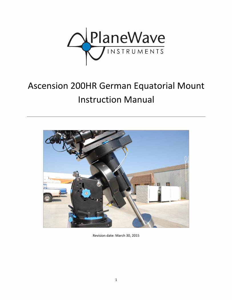
Contents Introduction ................................................................................................................................................................... 4
Unpacking and Crating................................................................................................................................................... 5
Installing the Pier ........................................................................................................................................................... 6
Installing the Mount on the Pier or Tripod .................................................................................................................... 8
Installing the Telescope on the Mount ........................................................................................................................ 15
Balancing the Telescope .......................................................................................................................................... 17
Note on using the Clutches ..................................................................................................................................... 18
Installing the Electronics and Powering up the Telescope .......................................................................................... 19
Installing the STI Control Software .............................................................................................................................. 20
Configuring the STI Control Software .......................................................................................................................... 23
Telescope Info Tab .................................................................................................................................................. 24
Miscellaneous Tab ................................................................................................................................................... 25
Mount Info Tab ....................................................................................................................................................... 26
Scope Encoders Tab ................................................................................................................................................ 26
Polar Alignment, First Mount Model and Setting the Home Switches ........................................................................ 27
Steps before making your first mount model ......................................................................................................... 27
Creating a Mount Model using PlateSolveXP .......................................................................................................... 27
Mount Model ............................................................................................................................................................... 36
Things That May Invalidate the Mount Model ........................................................................................................ 37
Creating a Mount Model ......................................................................................................................................... 38
Using the Telescope After Creating a Mount Model ................................................................................................... 44
Startup and shutdown of the Mount ...................................................................................................................... 44
Control via external software .................................................................................................................................. 44
Autoguiding ............................................................................................................................................................. 44
Appendix A – Dimensions ............................................................................................................................................ 47
Appendix B – Notes on the high resolution axis encoders .......................................................................................... 48
Encoder Adjustment ................................................................................................................................................ 48
Appendix C – Running Cables Through the Mount ...................................................................................................... 49
Appendix D – Converting sexagesimal to degrees and arcminutes ............................................................................. 53
Appendix E – Glossary of Terms .................................................................................................................................. 53
Appendix F - Power Requirements .............................................................................................................................. 54
Appendix G - Controlling the mount with TheSky 6 or TheSkyX.................................................................................. 55

3
Connecting to STI from TheSkyX ............................................................................................................................. 55
Connecting to STI from TheSky6 ............................................................................................................................. 57
Appendix H - Configuring the A200 for setup in the Southern Hemisphere ............................................................... 59
Appendix I - Using the RS-232 Port on the SiTech Controller ...................................................................................... 61

4
Introduction Thank you for your purchase of the PlaneWave Instruments Ascension 200 (A200) German Equatorial Mount. The
A200 mount is designed to give outstanding performance with up to 275 pounds of payload. It uses 360-tooth,
12.1 inch diameter RA and DEC gears, has built-in homing sensors on each axis, and is supplied with high resolution
encoders directly coupled to each axis. The high-resolution encoders correct for residual mechanical errors
including periodic error and declination backlash, thereby enabling long, unguided exposures. The stable tracking
and precise offsetting supported by the encoders also allow for very long guided exposures.
The Ascension 200 is intended for permanent observatories but can also be used for portable applications. The
mount breaks down into three components, making the mount transportable for field work. The heaviest
component is 96 pounds.
The PlaneWave Instruments Ascension 200 mounts are beautifully machined and finished, featuring black
anodized aluminum with stainless steel complements and fasteners.
Each A200 purchase includes:
Right Ascension and Declination axis assemblies
Control electronics based on the Sidereal Technology control system
Control software and ASCOM driver
PlaneWave 7.65 inch Saddle - or - PlaneWave tilt-in EZ Saddle for Losmandy style 3-inch dovetail plates
Counter-weight shaft
Shipping crate
The Unpacking and Crating section contains a full list of everything that comes with the mount.

5
Unpacking and Crating The Ascension 200 comes in one crate as shown in Figure 1. All of the items included in the crate are shown in
Figure 2. These items are listed below:
RA Axis and the Mount Base
Declination Axis
Counterweight Shaft
Counterweight Safety Stop (A200-148)
RA Base to Pier Bolts (4X 3/8-24 x 1-1/2 SHC)
Dec to RA Bolts (4X 1/2-13 x 1-1/4 BHC)
4 Communication Cables, 2X 4 pin and 2X 8 pin (gray cables with yellow tips), one of each per axis.
PlaneWave Saddle (200919) or EZ Saddle (600182)
Saddle Plate Mounting Hardware, 5x ¼-20x1-1/8 flat head or EZ Saddle Mounting Hardware, Mounting
Bolts, 4X ¼-20 x 7/8
24VDC Power Supply (#2099286) with AC power cord
4 Pin to Barrel Power Connector (adapts the power supply to the mount’s power input)
Electronics Box and USB Cable
Mounting Hardware for electronics box (2X ¼-20x3/8 SHC with plastic thumb screw and 4x plastic
washers)
Hand Paddle and Cable
USB drive with Software
Figure 1 - The crated A200 mount

6
Figure 2 - All of the major components that come with the A200 mount
Installing the Pier When installing the pier, take care to ensure that the bolt holes on the top plate of the pier are aligned to within a
few degrees of True North. The polar axis of the mount will eventually need to be precisely aligned to point North.
The base of the A200 mount can be adjusted in azimuth by up to +/-7.5 degrees, so the pier alignment will need to
be within that range.
One technique for aligning the pier is to simply use a compass. However, be aware that Magnetic North can be
offset quite a bit from True North depending on your location. The magnetic pole also drifts over time. As of this
writing, in the continental United States the offset ranges from about +16 degrees in Washington State, to 0
degrees in the Midwest, to about -16 degrees in Maine. The offset between Magnetic North and True North, called
the Magnetic Declination, can be calculated using a service on the NOAA website:
http://www.ngdc.noaa.gov/geomag-web/#declination
Another technique for determining the direction of True North is to hang a plumb-bob and mark the shadow that
is cast by the string when the Sun is at its highest point in the sky. This time is known as the transit time or "local
noon". The transit time for a particular location and date can be calculated using a service on the USNO website:
http://aa.usno.navy.mil/data/docs/RS_OneDay.php

7
The base of the Ascension 200 has 4 mounting holes used to bolt the base of the mount onto a pier plate. Please
see Figure 3 and note the orientation of North relative to the mounting hole pattern.
Figure 3 - The base of the A200 mount. The 4 corner holes are used to attach the mount to
the pier. The mounting holes are clearance holes for 3/8" socket head cap screws.
North

8
Installing the Mount on the Pier or Tripod The mount is rather heavy so it is best to do the installation in parts. It takes at least two strong people to lift the
Base/RA and the Declination assemblies. To install the mount on the pier:
1. Verify that the latitude adjustment bar is installed in the correct position for your current location. Refer
to Table 1 and Figure 4. This is normally preset for your site latitude by PlaneWave Instruments, but may
be adjusted as needed.
Latitude Position
0 - 20 degrees (Requires low latitude kit)
20 - 35 degrees Position 1
35 - 50 degrees Position 2
50 - 65 degrees Position 3
65 - 80 degrees Position 4
80 - 90 degrees Position 5
Table 1 - Latitude adjustment bar positions for various site latitudes
Figure 4 - Latitude adjustment components
If necessary, the latitude adjustment bar may be repositioned using the following procedure:
a. Loosen the blue latitude locking knobs on the either side of the mount's side plates.
b. Rotate the RA axis upward in altitude so it is out of the way, and tighten the blue altitude locking
knobs. Make sure the knobs are fairly tight so the RA axis does not slip down during this process.
c. Remove the 4 socket head screws (2 on each side) that hold the latitude adjustment bar in place
Latitude
adjustment
bar
1
2
3
4
5
Positions
Latitude
locking knob

9
d. Slide the latitude adjustment bar to the appropriate position for your latitude. See Table 1 and
Figure 4 to find the correct position.
e. Secure the latitude adjustment bar with the 4 socket head screws
f. Hold the RA axis firmly while loosening the blue latitude locking knobs on either side of the
mount's side plates. Gently lower the RA axis in altitude until the rear top surface rests against
the bottom of the latitude adjustment screw.
2. Place the mount base on top of the pier mounting plate as shown in Figure 5. NOTE: Be sure to tighten
the blue latitude locking knobs to keep the RA axis from moving when you lift it. It is easy to smash
your fingers!
Figure 5 - Placing the mount base onto the pier
3. Use the 4x 3/8-24 socket head cap screws (provided) to secure the base of the A200 to the mounting
plate of the pier. Use an Allen wrench to make sure these are tight.
Latitude locking knob

10
4. Adjust the mount latitude (i.e. polar altitude) to approximately match your site latitude. To measure the
approximate altitude angle of the mount, place an inclinometer along the top of the RA axis, as shown in
Figure 6. If you do not have an inclinometer on hand, there are many inclinometer / bubble level apps for
iPhone and Android phones that can measure inclination with reasonable accuracy.
Figure 6 - Refining the mount latitude adjustment
The angle of inclination of the RA axis should roughly equal your site latitude. To adjust the inclination:
a. Loosen the latitude locking knobs (one on each side of the mount)
b. Using a large wrench, turn the latitude adjustment knob clockwise or counterclockwise to raise
or lower the polar axis of the mount.
c. Once the measured mount latitude nearly equals the site latitude, tighten both latitude locking
knobs.
The latitude adjustment will be refined further in the Polar Alignment step. Note that this adjustment will
be somewhat more difficult once the mount is fully loaded. See Figure 9 for an illustration of how to lift
up on the counterweight bar to ease the load while making future adjustments.
Latitude adjustment
knob
Latitude locking knob
Inclinometer

11
5. Loosen the Right Ascension clutch knobs and rotate the right ascension axis so that the alignment pins are
roughly horizontal. See Figure 7. Tighten the clutch knobs when finished, or else the axis may slip during
installation of the Declination Axis! You only need to hand tighten these knobs.
Figure 7 - Location of the Right Ascension clutch knobs and alignment pins
6. Install the Declination axis, after verifying that the RA clutch knobs are at least hand tight. Lift the
declination axis with at least two people, as it is somewhat awkward to handle. You can see in Figure 8
how two people can lift it. There are two stainless steel alignment pins on the face of the RA axis, as
shown in Figure 7, which will guide the Declination axis into position and hold the axis in place while you
get the bolts to secure it. Once mounted, secure the axis with 4x 1/2"-13 button head cap screws
(provided).
Right Ascension clutch knobs
Alignment pins
12
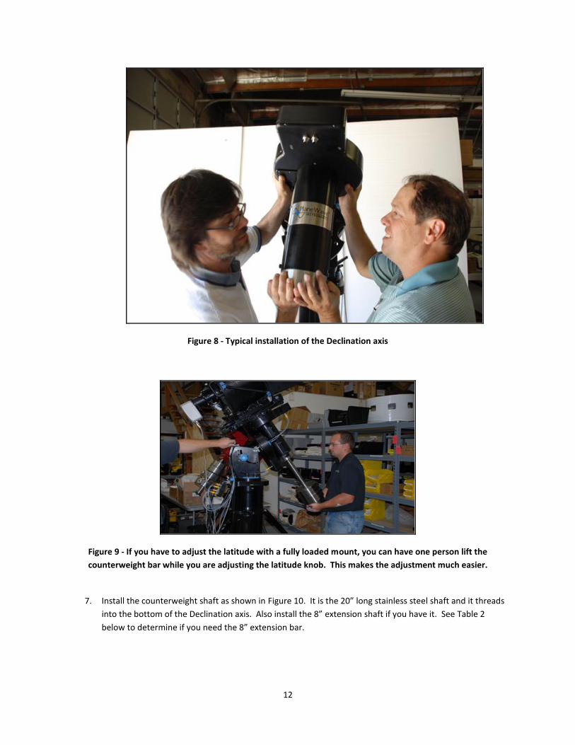
Figure 8 - Typical installation of the Declination axis
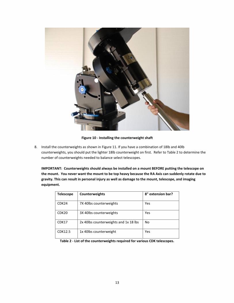
Figure 9 - If you have to adjust the latitude with a fully loaded mount, you can have one person lift the
counterweight bar while you are adjusting the latitude knob. This makes the adjustment much easier.
7. Install the counterweight shaft as shown in Figure 10. It is the 20” long stainless steel shaft and it threads
into the bottom of the Declination axis. Also install the 8” extension shaft if you have it. See Table 2
below to determine if you need the 8” extension bar.
13
Figure 10 - Installing the counterweight shaft
8. Install the counterweights as shown in Figure 11. If you have a combination of 18lb and 40lb
counterweights, you should put the lighter 18lb counterweight on first. Refer to Table 2 to determine the
number of counterweights needed to balance select telescopes.
IMPORTANT: Counterweights should always be installed on a mount BEFORE putting the telescope on
the mount. You never want the mount to be top heavy because the RA Axis can suddenly rotate due to
gravity. This can result in personal injury as well as damage to the mount, telescope, and imaging
equipment.
Telescope Counterweights 8" extension bar?
CDK24 7X 40lbs counterweights Yes
CDK20 3X 40lbs counterweights Yes
CDK17 2x 40lbs counterweights and 1x 18 lbs No
CDK12.5 1x 40lbs counterweight Yes
Table 2 - List of the counterweights required for various CDK telescopes.

14
Figure 11 - Installing the counterweights
9. Install the counterweight safety stop as shown in Figure 12. This prevents the counterweights from
accidentally sliding off the counterweight shaft and causing injury.
Figure 12 - Installing the counterweight safety stop

15
Installing the Telescope on the Mount 1. Run motor and sensor cables through the mount. See Appendix C
2. Run the accessory cables you will be using through the mount. See Appendix C. This needs to be done
prior to installing the PlaneWave Saddle Plate or the EZ Saddle. Examples of cables you may want to run
include: USB cables, power supply cables, and serial cables. You might also wish to run an AC extension
cord to supply power to cameras, filter wheels, and the EFA kit. Finally, you might find it convenient to
install a USB hub on the back of the telescope.
3. Install the PlaneWave Saddle Plate (Figure 13) or the EZ Saddle (Figure 14) depending on which one you
ordered.
Figure 13 - PlaneWave 7.6" saddle installed
Figure 14 - PlaneWave EZ Saddle installed
4. Install the CDK telescope onto the mount as follows.
a) Tighten the RA and Dec clutch knobs
b) Loosen the saddle bolts generously to easily allow the telescope to slide in
c) Set the leading edge of the dovetail into the saddle
d) Slide the telescope into the saddle and tighten the saddle bolts. See Figure 15.
e) Install stop screw(s) if available. See Figure 16.

16
Figure 15 - Installation of a CDK17 onto an A200 mount using a PlaneWave 7.6" Saddle
Figure 16 - Once the telescope is installed, you can place a ¼-20 SHC screw in the hole at the end of the dovetail
clamp as a safety stop. Depending on the balance of the telescope, this hole may not always be exposed.

17
Balancing the Telescope After the telescope is installed, you will need to balance the system.
The first step is to balance the Declination axis.
1. Start with the telescope/mount system in the configuration where the counterweights are pointed down
and the optical tube is pointed along the polar axis, as shown in Figure 17. Loosen the two blue clutch
knobs on the declination axis, as indicated in Figure 17. Be sure to hold the telescope in case it is grossly
out of balance! With the clutch loosened, rotate the telescope toward the horizon.
2. In this position, note when you release the optical tube whether the front rotates down or up. If the front
rotates down then the telescope is front heavy. If the front of the telescope rotates up, then it is back
heavy. If the telescope is front heavy then it needs to be moved back in the saddle plate. If the telescope
is back heavy then it needs to move forward in the saddle plate.
3. To move the telescope in the saddle plate:
a. Put the telescope back in the position shown in Figure 17
b. Have two people hold the back of the telescope
c. Loosen the saddle plate knobs to release the telescope
d. Slowly allow the telescope to slide back or push the telescope forward depending which way you
need to move it
e. Tighten the saddle plate knobs.
4. Repeat steps 1, 2, and 3 until the declination axis is balanced.
Figure 17 - The Ascension 200 mount in the starting position for testing balance
Declination
clutch knob
RA clutch
knob

18
Now the RA axis needs to be balanced.
BEFORE PROCEEDING, VERIFY THAT THE COUNTERWEIGHTS HAVE BEEN PROPERLY INSTALLED!
1. While holding the counterweight shaft, loosen the RA clutch knobs. The counterweight shaft is long and
gives you a lot of leverage to easily handle minor imbalances. Hold onto it in case the telescope is top
heavy and wants to fall. Rotate the RA Axis so the counterweight shaft is pointed toward the horizon.
2. Notice whether the mount wants to rotate so that the telescope goes down or up. If the telescope side
goes down then the telescope side is heavy and the counterweights need to be moved out or down on
the counterweight shaft. If the telescope rotates up, then the counterweights need to be moved up on
the counterweight shaft. In cases of extreme imbalance, weights may need to be added or removed.
3. When the counterweight shaft is in the horizontal position like this, you can loosen the counterweight
knobs and not have to worry about them sliding due to gravity and smashing your fingers. That really
hurts, so we recommend avoiding it. While in the horizontal position, loosen the counterweight lock
knobs and slide the weights in the appropriate direction to balance the telescope system. When the
telescope is balanced, the mount will not rotate with the clutches disengaged, but should glide smoothly
in either direction when you lightly push or pull on the end of the counterweight bar.
Note on using the Clutches Clutches are convenient for balancing the telescope system and quickly pushing the telescope to a particular
orientation for maintenance. Clutches are also nice because they allow the drive to slip harmlessly in the event of
hitting an obstruction. The clutch knobs should only be finger tightened. Do not use a tool to tighten the
clutches. When the clutch knobs are finger tight, they will not slip during normal slewing, but they will still be
allowed to slip should the telescope run into an obstruction.

19
Installing the Electronics and Powering up the Telescope The Ascension 200 mount uses a
Sidereal Technology Servo II Dual Axis
Telescope controller. We package the
electronics with a custom case and
cover, and we use high-quality
connectors and cabling.
The electronics box as seen in Figure 18
has motor and encoder connectors for
both the RA and Dec axes, a USB port, a
serial port, a hand paddle port, a 24VDC
power input port, a limit switch input
port, and an autoguider relay port.
The electronics board attaches to a
bracket mounted under the azimuth
polar alignment adjustment on the base
of the mount, as seen in Figure 19. The
electronics case is attached with two ¼-
20 x 3/8” SHC screws with thumb knobs. Do not use bolts longer than 3/8” as they can hit the electronics inside
the case. There are also 4 nylon washers. On each side, one washer goes between the case and the bracket while
the other washer goes between the bolt head and the bracket.
Figure 19 - Bracket for mounting the electronics case
Figure 20 - Attaching the electronics
Figure 18 - A200 mount electronics box

20
Installing the STI Control Software The A200 mount is operated via the STI (SiTech Interface) control software. The USB flash drive that comes with
the mount includes this manual and the software needed to control the A200 mount or other mounts that use the
PlaneWave controller. Figure 21 shows the contents of the USB flash drive.
Figure 21 - Contents of the USB memory stick
Here is an overview of the steps that need to be done for the installation.
1. Install .NET Framework 3.5 SP1 (if not already installed on your computer) 2. Install the STI control software 3. Install the APM catalog for PlateSolve 4. Install the ASCOM Platform (if not already installed) 5. If using TheSky 6, load the ASCOM plugin for TheSky6
1 - Install .NET Framework 3.5 SP1 (if not already installed) Both the STI control software and the ASCOM Platform 6 require the .NET Framework version 3.5 to be installed in order to operate. NOTE - Windows 7 includes .NET 3.5 by default, so this step is unnecessary on computers running Windows 7 or later. Additionally, many computers running Windows XP or Windows Vista will already have .NET installed. If you believe that .NET may already be installed, simply proceed to step 2. The STI installer will alert you if .NET 3.5 is not properly installed, and will offer to direct you to the Microsoft website where you can download the installer. The full .NET 3.5 SP1 installer is included on the USB disk that is distributed with the A200 mount. You may also download .NET 3.5 from: http://www.microsoft.com/en-us/download/details.aspx?id=22 2 - Install the STI control software The installer for the STI control software is included on the USB disk that is distributed with the A200 mount under the name "Setup_STI_1.x.x" You may also download the latest version of the A200 control software from http://planewave.com.

21
This installer will:
Install the STI program and data files
Install a USB driver for the SiTech telescope electronics
Register an STI-compatible ASCOM mount driver
Install several auxiliary utilities, such as ServoConfig and PlateSolve. Once finished, you should see a new icon for "PlaneWave STI" on the desktop, and a new group "PlaneWave STI" in the Start menu.
Figure 22 - New desktop icon and start menu entries
3 - Install the APM catalog for PlateSolve
STI uses a program called PlateSolve to match star patterns in camera images against known star positions in a star
catalog. PlateSolve is used to build accurate pointing models; this will be discussed later in the manual.
Because the catalog used by PlateSolve is rather large (over 400 MB), the catalog is distributed as a separate file. It
may be found on the included USB disk under the name "Setup_APM_Catalog".
Note that this process will not create any new icons or program groups. However, it may be uninstalled via "Add or
Remove Programs" under Control Panel.
4 - ASCOM Platform
The ASCOM Platform allows third party programs, such as Maxim
DL and TheSky, to control the A200 mount via the STI control
software. You may download the latest version of ASCOM from:
http://ascom-standards.org/
On the right side of the website, there should be a link to
download ASCOM Platform 6 as shown in Figure 23.
Additionally, the latest ASCOM installer as of this writing (ASCOM
Platform 6 SP1) is included with the USB disk that comes with the
A200 mount.
Figure 23 - ASCOM website screenshot

22
5 - ASCOM Plugin for TheSky6 (not needed for TheSkyX)
If you plan to control your A200 mount from TheSky6 (a planetarium program made by Software Bisque), you will
need to install an ASCOM plugin to allow TheSky to communicate with ASCOM devices, including STI. These plugins
are distributed on the USB disk that comes with the mount, and you may install them now. However, the mount
hardware and software must be fully set up and configured before attempting to connect from TheSky.
For full instructions on controlling the mount via TheSky 6 or TheSkyX, please refer to Appendix G.

23
Configuring the STI Control Software STI Control Software is a PC based program that controls the Ascension 200 mount. The motor controller may also
be used on other mounts that use the Sidereal Technology motion controller, including mounts made by Mathis
Instruments. STI also acts as an ASCOM driver for the mount. The main STI window is shown below.
Figure 24 - STI home screen

24
Begin by connecting the supplied USB cable to the USB port on the mount electronics box, and plugging the other end into the computer or a connected USB hub. Windows should detect the new device and load the proper drivers, which were installed with the STI installer. Next, launch STI and click on the "EDIT CONFIG" button.
Figure 25 - Edit Config button
Telescope Info Tab
The first tab in the Setup screen contains some basic parameters about your site and telescope. The most
important parameters to adjust on this screen are:
Longitude and Latitude (the mount must know its location in order to accurately point at stars)
Focal Length of the telescope (in order to reliably find PlateSolve solutions during a mount model.)

25
Miscellaneous Tab
The most important setting on this screen is the "Comm Port". You must set this to the COM port that is associated
with the with USB connection on the mount electronics box.
One method for identifying the correct COM port is to open Windows Device Manager, expand the "Ports"
category, and look for the port that is listed as a "USB Serial Port". In the example below, the A200 mount is
connected on COM8. Note however that some other devices, such as Boltwood II Cloud Sensors, may also be
identified as USB Serial Ports.
In addition, the "Camera FOVX" and "Camera FOVY" values should be configured to the unbinned field of view for
your camera / telescope combination. These numbers are used by PlateSolve during the automated mount
modeling process to determine your approximate image scale.
If you do not know your field of view, enter the Camera X Pixels, Camera Y Pixels, X Microns per Pixel, and Y
Microns per Pixel (typically available from your camera spec sheet) and click "Calculate Field of View". The field of
view will be calculated using these values, as well as the Focal Length value entered on the Telescope Info page.

26
Mount Info Tab
The default settings for the A200 are shown above. It is typically not necessary to change these.
Scope Encoders Tab
The default settings for the A200 with High-Resolution Axis Encoders are shown above. For mounts with high
resolution encoders, like the A200HR, Cascade mode needs to be selected. To disable the axis encoders, select
Ignore.

27
Polar Alignment, First Mount Model and Setting the Home Switches
NOTE: If you are located in the southern hemisphere, please refer to Appendix H before continuing.
The Ascension 200 mount is a German Equatorial mount. This means that when the mount's polar axis is aligned
to the Earth’s rotational axis, the mount need only track in one axis to counteract the rotation of the Earth.
Polar alignment is the process of adjusting the polar axis of the mount (also known as the Right Ascension axis) to
be aligned with Earth's rotational axis. For non-computerized telescopes this is typically done using a process
called the Drift method, an iterative process that is time consuming and requires some expertise.
Since the Ascension 200 is a computerized mount with sophisticated star-matching and pointing model software,
the process is much easier. The first step is to make a small mount model, in which you align the telescope to
about 6 or 8 known stars. Using this information, the mount modeling software will calculate the polar
misalignment of the mount.
At that point the mount can be manually adjusted in azimuth and in latitude/altitude by the amount reported by
the software. This process will bring the mount closer to proper polar alignment.
Steps before making your first mount model The mount and the telescope should be installed as described in previous chapters. After the initial installation,
the mount should be within +/-5 degrees from true North in azimuth and within +/- 5 degrees of the correct
latitude.
Before continuing, make sure that the telescope electronics are powered on, and that STI is properly connected to
the mount.
You may also want to align a finder scope to the main imaging telescope before continuing.
Creating a Mount Model using PlateSolveXP In order to determine the mount's polar misalignment, you will need to create a small mount model. Since the
telescope is not polar aligned, the pointing accuracy of the mount will initially be very poor as you move around to
different points in the sky. We will start by making a small mount model using an aligned finder scope. We will
then make a more accurate automated mount model using the main imaging telescope and CCD camera to
precisely determine the mount's polar misalignment.
1. Open STI
2. Open Maxim DL and connect to your CCD camera. If you have a filter wheel, select the "brightest" filter --
that is, the filter that allows the most light through (typically Luminance, Clear, or Empty).
3. Select the Chart menu from the top menu bar of the STI window. Select “Show Sky Chart”. This will open
the sky chart window.

28
4. Click on the "Commands" menu and select "Home". The Homing Operations Window will open. Press the
“Initialize Scope Using Homing Switches” button. The telescope will slew to its home position. For the
A200, this corresponds to the orientation in which the counterweight bar is pointed down and the
telescope is pointed at the celestial pole. This procedure, called "homing the mount", is used to calibrate
the mount axes to a known position at startup.
29
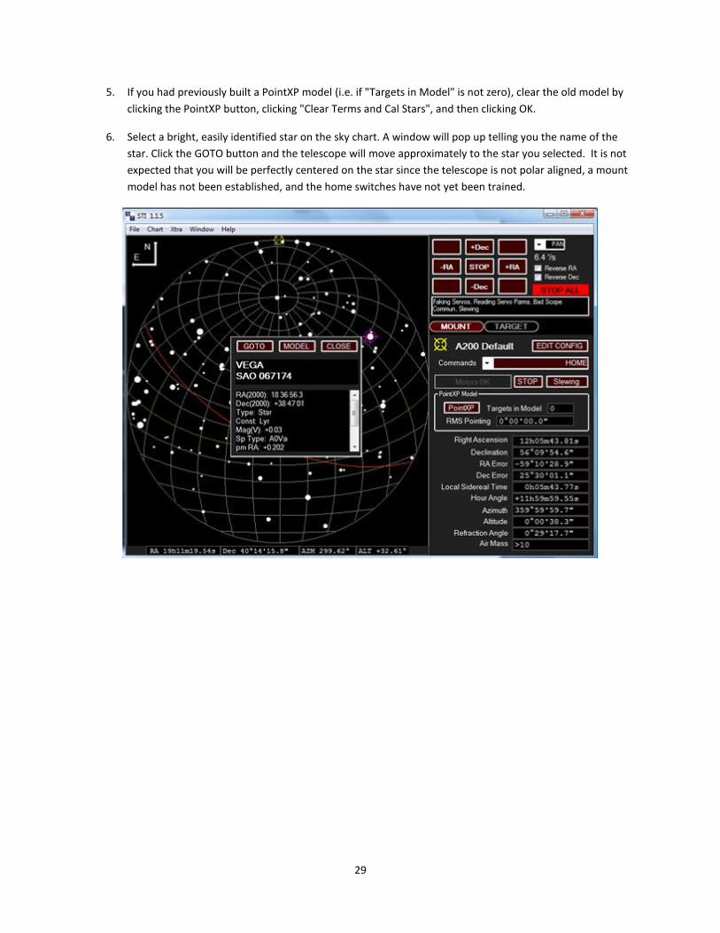
5. If you had previously built a PointXP model (i.e. if "Targets in Model" is not zero), clear the old model by
clicking the PointXP button, clicking "Clear Terms and Cal Stars", and then clicking OK.
6. Select a bright, easily identified star on the sky chart. A window will pop up telling you the name of the
star. Click the GOTO button and the telescope will move approximately to the star you selected. It is not
expected that you will be perfectly centered on the star since the telescope is not polar aligned, a mount
model has not been established, and the home switches have not yet been trained.
30
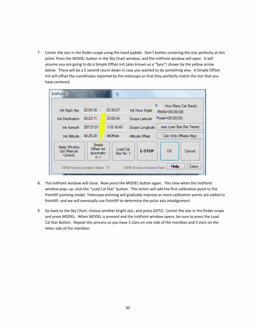
7. Center the star in the finder scope using the hand paddle. Don’t bother centering the star perfectly at this
point. Press the MODEL button in the Sky Chart window, and the InitPoint window will open. It will
assume you are going to do a Simple Offset Init (also known as a "Sync") shown by the yellow arrow
below. There will be a 5 second count-down in case you wanted to do something else. A Simple Offset
Init will offset the coordinates reported by the telescope so that they perfectly match the star that you
have centered.
8. The InitPoint window will close. Now press the MODEL button again. This time when the InitPoint
window pops up, click the "Load Cal Star" button. This action will add the first calibration point to the
PointXP pointing model. Telescope pointing will gradually improve as more calibration points are added to
PointXP, and we will eventually use PointXP to determine the polar axis misalignment.
9. Go back to the Sky Chart, choose another bright star, and press GOTO. Center the star in the finder scope
and press MODEL. When MODEL is pressed and the InitPoint window opens, be sure to press the Load
Cal Star Button. Repeat this process so you have 3 stars on one side of the meridian and 3 stars on the
other side of the meridian.

31
10. Now it is time to build a more accurate mount model using the CCD camera on your telescope. Go to the
Commands menu and select Run Script at the bottom.
11. The Script window will open as seen below. The three arrows point to the most important settings for
doing an automatic mount model run. For this initial polar alignment step, you should change “How
Many Cal Points”, to 6. Later, when doing a full pointing model, you will want to map 30-40 points.
Exposure time depends on your telescope, camera, selected filter, and site conditions. It should be long
enough to get at least 10 good star detections that can be used for an automatic PlateSolve. Binning
should normally be set to 2.

32
12. Once the parameters described above are set, press the “Make PointXP Run” button. This will open a
new program called CalPointsXP which will select the optimum positions for the cal points. The window
will automatically close after 60 seconds, but you can simply close it immediately before proceeding.
You should now see a pointing run script in the Script window, shown with the yellow arrow below.

33
13. Press the PLAY button in the Script window. This will run the script and start the auto mapping run. The
PointXP script will cause the telescope to slew to the first calibration point position, take an image, plate
solve the image (accurately determine the position of the telescope by comparing the stars in the image
to a known star catalog), and add the position information to the mount model.
The window that pops up is the PlateSolveXP window. The "Status" section will show the progress of the
plate matching process, which involves loading the image, identifying ("extracting") stars in the image,
and searching in a star catalog around the region of the mount's reported coordinates to find a match.
PlateSolveXP will search up to 999 regions in an expanding spiral pattern before giving up. Once you have
a few points in your pointing model, you should typically get a match after searching fewer than 50
regions. If you want to abort a search on a poor-quality image, click "Stop Search", and STI will proceed to
the next calibration point.
34
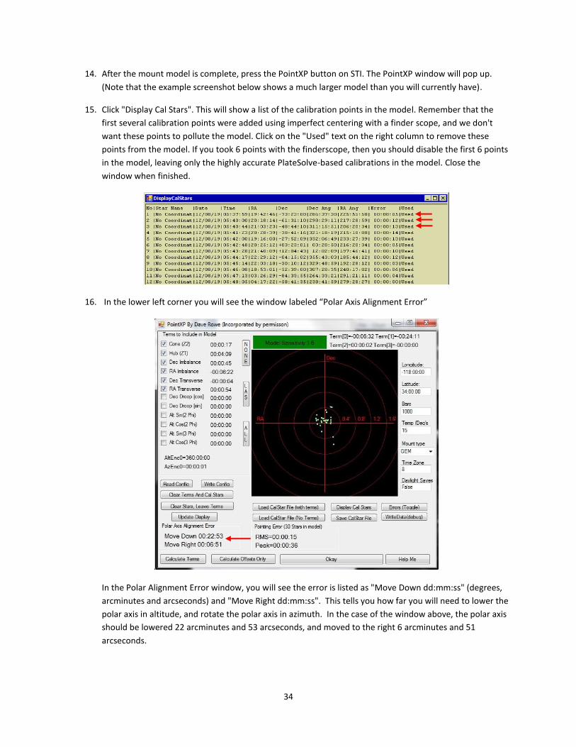
14. After the mount model is complete, press the PointXP button on STI. The PointXP window will pop up.
(Note that the example screenshot below shows a much larger model than you will currently have).
15. Click "Display Cal Stars". This will show a list of the calibration points in the model. Remember that the
first several calibration points were added using imperfect centering with a finder scope, and we don't
want these points to pollute the model. Click on the "Used" text on the right column to remove these
points from the model. If you took 6 points with the finderscope, then you should disable the first 6 points
in the model, leaving only the highly accurate PlateSolve-based calibrations in the model. Close the
window when finished.
16. In the lower left corner you will see the window labeled “Polar Axis Alignment Error”
In the Polar Alignment Error window, you will see the error is listed as "Move Down dd:mm:ss" (degrees,
arcminutes and arcseconds) and "Move Right dd:mm:ss". This tells you how far you will need to lower the
polar axis in altitude, and rotate the polar axis in azimuth. In the case of the window above, the polar axis
should be lowered 22 arcminutes and 53 arcseconds, and moved to the right 6 arcminutes and 51
arcseconds.

35
17. To move the polar axis in azimuth, loosen the six azimuth locking knobs shown in Figure 26 below.
Assuming the polar axis needs to be moved to the right, first loosen the azimuth adjustment knob on the
left, then tighten the Azimuth Adjustment Knob on the right.
NOTE 1: For the Azimuth Adjustment Knob: 1 turn = 0.4 degrees (24 arcminutes).
NOTE 2: For a Mathis mount, please see the included mount manual for this information.
In the example above, the polar alignment needs to be adjusted by 6 arcminutes and 51 arcseconds. That
is the same as 6.85 arcminutes. See Appendix D for the conversion equation.
To calculate how much to turn the azimuth adjustment knobs, take the polar misalignment in arcminutes
and divide it by 24. This will give you the number of turns. In our example,
6.85/24 = .28 turns, or just over a ¼ turn. We would loosen the azimuth adjustment knob on the left by at
least 1/4 turn, tighten the azimuth adjustment knob on the right by 1/4 turn (which rotates the entire
mount in azimuth), and then tighten the left knob.
Once the azimuth has been adjusted, tighten the six azimuth lock knobs.
To move the polar axis in altitude, first loosen the Altitude Lock knobs. In our example, the polar axis
needs move down 22 arcminutes and 53 arcseconds, or 22.88 arcminutes. (See Appendix D)
NOTE: For the Altitude Adjustment Knob: 1 turn = 1/2 degree (30 arcminutes)
To calculate how many turns to move the Altitude Adjustment Knobs, take the polar misalignment in
arcminutes and divide it by 30. This will give you the number of turns. In our example,
22.88/30 = 0.95 turns, or just about 1 full turn.
Once the altitude has been adjusted, tighten the Altitude Lock knobs.

36
Figure 26 - Polar alignment adjustment components
Your mount should now be much closer to proper polar alignment. A new mount model should be created, as
described in the next section. If the new mount model still indicates a significant polar misalignment, repeat these
steps until the alignment error is under about 10 arcminutes in each axis. The best you can expect to do with
reasonable effort is about 1 arcminute of alignment error in each axis. The PointXP model will be able to
compensate for any residual misalignment.
Mount Model A mount model is a very accurate way of aligning the telescope to the sky. It improves both the pointing and the
tracking of the telescope system. It does this by comparing a series of mount positions against positions on the sky,
measured by either performing a PlateSolve or manually centering a star in the telescope. The model has several
different correction variables, and these variables are fit against the measured position errors to minimize the RMS
error and improve telescope pointing. A reasonable model should contain 16-40 points distributed across the sky.
However, the mount should begin pointing reasonably well after just 4 or 5 points.
Once a mount model is created, it can be saved and reused each time the telescope is powered on and homed.
The model should remain valid until some physical alignment of the mount, telescope, or imaging system changes.
When the mount is first powered on, it is "lost" and needs to be calibrated against some known reference position.
There are three common ways of initializing the mount:

37
1. "Homing" the mount. This instructs the mount to slew to a position where a set of "home switches" are
triggered. These switches are located at a known position, and can be used to initialize the coordinate
system of the mount.
2. "Parking" and "Unparking" the mount. When the mount is in a known position, "Parking" the telescope
will cause it to slew to a predefined position and then stop all motion. The mount can then be turned off,
and turned back on at a later time. When the mount is "Unparked", the control system assumes that the
mount is still positioned at the same point as when it was parked, and initializes the coordinate system
using that information. (Note: If the mount has been moved, e.g. by loosening and tightening the clutch
knobs, since the last Park, the mount will not be correctly positioned for an Unpark and must be initialized
using one of the other methods.)
3. Calibrating to a sky position using Offset Init. At startup, the mount is manually positioned to some
reference point in the sky, such as a bright star. When the star is centered, an "Offset Init" is performed,
which initializes the mount's coordinate system so that its current position corresponds to the current
position of the target star. This is also known as "syncing" the mount.
The procedure for saving and associating a pointing model for each of these initialization techniques will be
described below.
Things That May Invalidate the Mount Model Changing the collimation of the telescope
Changing from a camera to an eyepiece with a diagonal, where the diagonal is not perfectly at 45 degrees.
Changing telescopes – if you change telescopes, or remove and reinstall your existing telescope from the
mount, you may need to create a new model
Adding or removing significant weight from the telescope.
All of these changes will affect the mount model, although in some cases the effect may be small enough to ignore.
To evaluate how well the telescope is pointing, try slewing to a few bright stars. For each bright star, take an image
and measure how close to the center of the CCD the star is positioned. If the pointing accuracy is negatively
impacted enough, you can create another mount model. You can even have multiple mount models, one for each
equipment setup if you need it. Contact PlaneWave Instruments for details on how to do this.

38
Creating a Mount Model 1. Open STI, if it is not already running.
2. Open Maxim DL and connect to your CCD camera. If you have a filter wheel, select the "brightest" filter --
that is, the filter that allows the most light through (typically Luminance, Clear, or Empty).
3. Select the Chart menu from the list of options on the top of the STI window. Select “Show Sky Chart”.
This will open the sky chart window.

39
4. Click on the "Commands" menu and select "Home". The Homing Operations Window will open. Press the
“Initialize Scope Using Homing Switches” button. The telescope will slew to its home position. For the
A200, this corresponds to the orientation in which the counterweight bar is pointed down and the
telescope is pointed at the celestial pole.
5. Clear the old PointXP model by clicking the PointXP button, clicking "Clear Terms and Cal Stars", and then
clicking OK.
6. From the Commands menu, select Run Script.

40
7. The Script window will open as seen below. The three arrows point to the most important settings for
doing an automapping run. Since this is going to be the main model for the telescope, set the number of
stars to be somewhere between 16 and 40. More points will take longer to acquire, but should result in a
more representative mount mode. Set the exposure time so that a typical image will result in at least 10
good star detections in an image. A binning value of 2 is normally OK, but if your stars are undersampled
(smaller than 2x2 pixels in the resulting images), change this to 1.
8. Press the “Make PointXP Run” button. This will open a new program called CalPointsXP which will select
the optimum positions for the calibration points. You may close the CalPointsXP window immediately.

41
9. An automapping script will be generated in the scripting window, as shown below.
10. Press the PLAY button in the Script window. This will run the script and start the auto mapping run. The
PointXP script will cause the telescope to slew to the first calibration point position, take an image, plate
solve the image (accurately determine the position of the telescope by comparing the stars in the image
to a known star catalog), and add the position information to the mount model.
The window that pops up is the PlateSolveXP window. The "Status" section will show the progress of the
plate matching process, which involves loading the image, identifying ("extracting") stars in the image,
and searching in a star catalog around the region of the mount's reported coordinates to find a match.
PlateSolveXP will search up to 999 regions in an expanding spiral pattern before giving up. Once you have
a few points in your pointing model, you should typically get a match after searching fewer than 50
regions. If you want to abort a search on a poor-quality image, click "Stop Search", and STI will proceed to
the next calibration point.
11. After the mount model is complete, press the PointXP button on STI and the PointXP window will pop up.
You may inspect the model, and reject points that appear to be erroneous.

42
12. Now that you have a complete mount model, you must calibrate the positions of the home switches using
the model information. You must do this one axis at a time. Under Commands list, select HOME. This will
open the HOME dialog box as seen below.
13. Notice that there are two Find Transition Angle buttons on the dialog box, one for the Primary Axis (RA)
and one for the Secondary Axis (DEC). Press the Find Transition Angle button for the Secondary Axis first.
For the A200, the mount will slew in declination until the telescope is pointed at the pole. A new number
for the Transition Angle will be displayed that is close to, but not exactly, 90 degrees. After the Secondary
Axis has been calibrated, press the Find Transition Angle for the Primary Axis. For the A200, the mount
will slew in right ascension until the counterweight bar is pointed down. When it is complete, the
transition angle should be close to, but not exactly, 270 degrees.
14. Press the OK button. This will save the PointXP file as HomePointXP.PXP for future use, and will also save
the new home switch transition angles. Do not click cancel or simply close the Homing Operations
window, or this information will be lost and you will need to build a new pointing model!
15. If desired, set a park position. Slew the telescope manually with the hand pad or the buttons on STI until
the telescope is at the desired park position. For roll-off observatories, this usually involves pointing the
telescope in a horizontal position so as to clear the roll off roof.

43
16. Once the telescope is at the desired park position, hit the STOP button to turn off tracking. Then from the
Commands menu, select SET PARK. Once this is done, open the Commands menu and select PARK. This
writes the current mount model to a file called ParkPointXP.PXP for future use.

44
Using the Telescope After Creating a Mount Model
Startup and shutdown of the Mount Once you have polar aligned and built a PointXP model for the mount, it is ready for general use. Normally the
telescope will be used in the evening and shut off during the day. This section talks about how to start up and shut
down the mount.
There are three ways to get up and running with an existing mount model. First, if you PARKed the telescope the
last time you shut down the mount, you can UNPARK the telescope to retrieve its previous position. Once the
mount has been unparked, the "Park" PointXP model will be loaded and the telescope will be ready to slew.
Another method to start up is to initialize the telescope using is home sensors. This assumes that you calibrated
the home sensors the last time you build a pointing model. If you open the Commands menu and select the HOME
option, the mount will move to its home position, initialize the coordinate system based on the calibrated home
switch angles, and load the "Home" PointXP model.
The third option is to recall a previously saved mount model and then perform a Simple Offset Init (also called a
"sync") on a reference star.
At the end of an observing session, you can PARK the mount, which will slew the telescope to the position you
previously set as the PARK position, and turn off tracking. You can also simply turn off power to the mount,
although if you do this you MUST home the mount the next time you turn it on. (You cannot use the UNPARK
procedure). Finally, you can simply stop tracking and leave the mount powered on until your next observing
session.
Control via external software The STI control software manages the basic operation of the mount. However, STI does not have an extensive
database of interesting targets in the sky beyond some bright stars and Messier objects. It also does not manage
extended observing sessions for you. To support these operations, STI may be controlled from other programs
using its ASCOM interface. It is very common to operate STI via another program, such as TheSky (see Appendix G),
ACP, or CCDAutoPilot.
Autoguiding Autoguiding is the process of taking repeated images of a guide star, detecting any drift or positioning error on
that star, and sending a correction offset to the mount to put the star back at the desired position.
There are two different ways to send these offset signals. One way is called "relay guiding". This is where the
guide camera is connected to the motor control box and as the guide star drifts, the CCD camera sends electrical
guide signals to the motor control box. In a sense, the guide camera is pressing virtual handpaddle buttons to
nudge the mount's position slightly. There is a port labeled "Autoguider" on the motor control box for this use.
However, relay guiding bypasses the axis encoders on the A200 and therefore does not produce a highly accurate
offset. Relay guiding is not recommended for the A200 mount or any other mount with high resolution
encoders.
The recommended method of autoguiding for the A200 is called "pulse guiding", also known as "ASCOM guiding".
In this method, as the guide star drifts on the guide camera, the camera control software (for example, MaxIm DL)
45
notes this movement and sends ASCOM commands to STI in order to make the appropriate corrections. Pulse
guiding is beneficial because it doesn’t use any additional cables and it uses feedback from the high resolution axis
encoders to produce extremely accurate offsets.
To set up pulse guiding with MaxIm DL version 5:
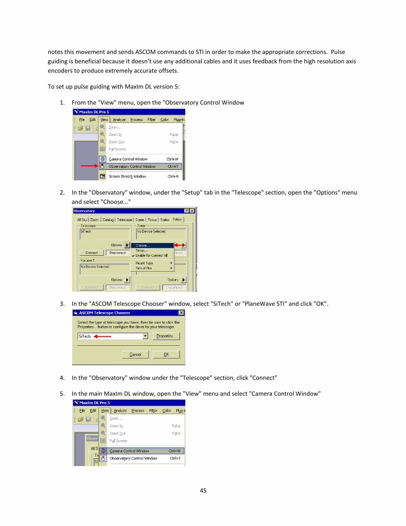
1. From the "View" menu, open the "Observatory Control Window
2. In the "Observatory" window, under the "Setup" tab in the "Telescope" section, open the "Options" menu
and select "Choose..."
3. In the "ASCOM Telescope Chooser" window, select "SiTech" or "PlaneWave STI" and click "OK".
4. In the "Observatory" window under the "Telescope" section, click "Connect"
5. In the main MaxIm DL window, open the "View" menu and select "Camera Control Window"

46
6. In the "Camera Control" window, select the "Guide" tab and click "Settings"
7. In the "Guider Settings" window under "Autoguider Output", pull down the "Control Via" menu and select
"Telescope". Click "OK".
MaxIm will now send all guide commands via ASCOM to the configured Telescope device -- in this case, STI.

47
Appendix A – Dimensions

48
Appendix B – Notes on the high resolution axis encoders The A200HR has built in high resolution encoders that are directly coupled to each axis. The encoders are located
directly underneath RA axis gear and the DEC axis gear. They are couple directly to the RA and DEC shafts so the
encoders always record the movement of the telescope whether the clutches are engaged or not, or even if the
clutches slip.
The high resolution encoders are used to position the telescope, and as a feedback mechanism for high-precision
tracking. The mount has anywhere from 5 to 10 arcseconds of peak-to-valley periodic error due to the worm gear
and gear train. However, the axis encoders detect and remove any deviation from the desired position at about 20
cycles per second, essentially removing effects such as periodic error, belt slack, backlash, and other motor drive
imperfections. The RMS tracking error during calm conditions is typically 0.14 to 0.25 arcseconds.
If you notice RMS tracking errors consistently above 0.25 arcseconds and cannot attribute this to external factors
such as wind, then the telescope balance or gear train may need to be adjusted.
The behavior of a telescope system is dictated by numerous variables, and many tradeoffs must be balanced. As an
example, a very strongly preloaded worm will make the system more stiff and reduce undesired motion. However,
this creates more friction during slewing and normal tracking motion, causing the RMS tracking error to increase.
For the smoothest possible tracking, the worms need a weaker spring force preload.
The correct preload setting must balance mount stiffness and tracking smoothness. The spring tension of the
worms may be adjusted if needed. The covers will need to be removed in order to access the preload spring.
Encoder Adjustment The high resolution encoders are very precise measuring devices. The spacing of the encoder read head relative to
the encoder disk is critical, and there is a low tolerance for error. The ideal spacing between the read head and the
disk is .8mm, with a tolerance of +/-0.1mm. This means that the read head must be positioned within a window of
about .008” or 200um. The mount is made from aluminum and the encoder disk is made of stainless steel, so over
large temperature swings there is differential expansion/contraction. It is possible that the read head is installed
close to the edge of the tolerance zone, in which case a large temperature change could degrade the signal quality.
If you suspect the encoder is having problems, you can remove the two set screws on the side of the gear housing.
Figure 27 shows the location of these screws on the RA axis. With these set screws removed you can see the
encoder status LED. The indicator light will either be green, yellow or red. If the light is yellow or red, then there is
a spacing problem.

49
Figure 27 Two set screws for adjusting the read head position and viewing the encoder signal strength LED.
Green indicates a strong signal, Orange indicates a weak signal, and Red indicates no signal.
On the underside of each gear housing cover is a panel that can be removed. This panel houses the high resolution
encoder read head. If there needs to be adjustment, it can be done by removing this panel. Please contact
PlaneWave Instruments for instructions on adjusting the read head.
Appendix C – Running Cables Through the Mount The A200 mount is designed to allow cables to easily run through the mount. At minimum, the two cables for the
Declination motor and encoder/home switch should run through the mount. In addition, it is very convenient to
run cables for CCD cameras, the EFA kit, and other accessories so that there are no dangling cables that can tangle
during operation. It may also be convenient to run an AC extension cable through the mount in order to power
cameras, filter wheels, the focus motor, and other accessories.
The first step in cabling any A200 mount is to run the Declination motor/sensor cables:
1. Remove the cover that is indicated in Figure 28
2. Run one pair of yellow-tipped cables (one with 4 pins, one with 8 pins) down through the front of the RA
axis as shown in Figure 29.
3. Run the pair of cables up along the upper cable channel on either side of the mount, and screw the cables
into the plugs on the underside of the Declination gear housing.
4. Use the upper channel retaining clips (similar to those indicated in Figure 30) to hold the cables in place.
See Figure 28 for a complete example of the Declination motor/sensor cable routing.

50
Figure 28 - This access panel should be removed to run cables down the RA axis.
Figure 29 - Running a cable down from the top of the RA axis

51
Figure 30 - Cable channel retaining clips
To run cables from the back of the telescope through the mount:
1. Remove the telescope and dovetail plate. (Optional in some configurations. The larger CDK telescopes
include dovetail plates with slotted holes that cables may run through.)
2. Find the end of the cable that will be connected at the "pier" end of the observatory -- for example, the
male end of a 3-prong AC extension cable
3. Drop the cable through the hole at the top of the DEC axis, and look for it to drop out of the bottom of the
axis (near the counterweight bar mounting point).
4. Pull the cable out from the side of the DEC axis, run it up along one of the lower cable channels, and drop
it down through the top of the RA axis, as shown in Figure 31.
5. Push the cable through the top of the RA axis until it comes out the back of the mount.
When all cables have been run:
1. Secure the cables using the retaining clips shown in Figure 30
2. Replace the side plate shown in Figure 28.
3. Replace the dovetail plate and telescope if they had originally been removed. Note the cable channel
between the DEC hub and the dovetail plate. Cables should be run to the back of the telescope via this
channel.
Figure 32 shows a fully assembled telescope, with cables running through the mount.

52
Figure 31 - A cable coming out the bottom of the DEC axis and routed through the top of the RA axis
Figure 32 - Cables running through a fully assembled mount

53
Appendix D – Converting sexagesimal to degrees and arcminutes Angles in astronomy are commonly represented in sexagesimal units, which divides an angle into degrees,
arcminutes, and arcseconds:
DD:MM:SS
where an arcminute is 1/60 of a degree, and an arcsecond is 1/60 of an arcminute.
For example, a declination of:
12:30:00
represents an angle of 12 degrees, 30 arcminutes, and 00 arcminutes, or 12.5 decimal degrees.
To convert a sexagesimal value DD:MM:SS to degrees, calculate the following:
Degrees = DD + MM/60 + SS/3600
As an example, the declination is Vega is 38:47:01. This converts to 38 + 47/60 + 1/3600 = 38.78361 degrees.
To convert a value in degrees to a value in arcminutes, simply multiply the value in decimal degrees by 60. As an
example, a polar alignment offset of 00:05:34 is equal to 0 + 5/60 + 34/3600 = 0.0927 degrees, or 0.0927*60 =
5.566 arcminutes.
Appendix E – Glossary of Terms Cone (or Cone Error): Cone is the angular error which measures the non-perpendicularity between the
optical axis and the DEC axis / Alt axis. If you had a telescope that had zero cone error and you could
induce the error by adding a shim to the front of your dovetail plate, tilting the telescope up slightly. The
term "cone" comes from the notion that in a telescope with cone error, the optical axis will trace out a
cone shape (rather than a perfect plane) as you rotate 360 degrees in declination.
Hub: Hub is the angular error which measures the non-perpendicularity between the RA and Dec axes, or
Azimuth and Altitude for an Alt/Az mount.
Offset Init or Offset Initialization: This defines the mount's position for one point in the sky. If you point
to a star in the sky and do an Offset initialization, then the telescope's relative position is defined as the
position of that star. This is usually done prior to creating a mount model. The term "Sync" is also
commonly used in telescope control software to denote this concept.
PlateSolve: Taking an image of a star field and matching against a known database of stars, thereby
defining the true center of the telescope field very accurately. This is useful when creating a telescope
mount model as it yields a very accurate pointing position of the telescope + mount system.
Polar Alignment: Equatorial mounts, like the Ascension 200, have two orthogonal axes of motion. One
axis is called the Right Ascension axis, or RA. If the RA axis is parallel to the Earth’s axis of rotation, then
the mount is said to be polar aligned. The advantage of an equatorial mount is that in order to cancel out
the rotation of the Earth, the RA axis simply needs to move at a constant rate of 1 rotation every 24 hours
(approximately).

54
Mount Model: A mathematical algorithm that corrects the positioning of a telescope mount for
repeatable mechanical, positional, and atmospheric errors. Mechanical errors include flexure, non-
perpendicularity of the RA and DEC axes, and non-perpendicularity of the optical axis to the DEC axis.
Positional errors include polar misalignment, not being perfectly level, and not having the position of the
telescope on Earth perfectly configured. Atmospheric errors include refraction as you change your
altitude. By using 16 to 40 modeling points, the mount model algorithm can correct for these errors to
improve the pointing and tracking of the telescope.
RMS: Root mean square, a way of characterizing a whole group of data and measuring how far the data as
a whole deviates from the average or ideal value. In a telescope system it is generally used as a
measurement of error. For example, RMS tracking error describes how much a telescope deviates from
perfectly following a moving star, and RMS pointing error describes how well a telescope mount can be
expected to center a target after a slew.
Appendix F - Power Requirements The A200 runs off of 24VDC and requires around 5 amps to run. But it is nice to have a 9 to 10 amp power supply
to account for the momentary higher currents being needed. We supply at 100VAC to 240VAC that uses 4 amps
and outputs 24VDC, 9.2 amps.

55
Appendix G - Controlling the mount with TheSky 6 or TheSkyX The STI control software includes an ASCOM driver which allows third party programs to control the mount. One
popular choice for controlling telescopes is to use TheSky, a software package developed by Software Bisque.
Recent versions of TheSkyX can communicate with ASCOM mounts without the need for any additional plug-ins.
TheSky6 requires an extra plug-in that will allow it to connect to an ASCOM mount driver.
The mount must be plugged in, turned on, and communicating with a properly configured instance of STI before
continuing. If you have not done so already, please continue setting up the mount before completing the
integration with TheSky.
Connecting to STI from TheSkyX 1. Make sure you are running TheSkyX version 10.2.0 Build 7773 or later. (Versions as far back as Build 6949
may work, but have not been tested by PlaneWave Instruments.)
As of October 2014, Software Bisque makes a distinction between “official” releases and Daily Builds. The
latest official release as of this writing is 10.2.0 Build 6409, which does NOT include build-in support for
ASCOM mounts. Even if you use the “Check for Updates” feature under the Help menu when using Build
6409, the software will not report that a new version is available. You must download and install the
latest Daily Build of TheSkyX from the Software Bisque website in order to use an ASCOM mount driver.
2. Launch TheSkyX
Latest daily build (supported)
Build 6409 (not supported)

56
3. Go to the "Telescope" menu and select "Telescope Setup..." to bring up the Imaging System Setup
window.
4. Click the "Mount Setup" menu and select "Choose..."
5. Expand the "ASCOM" category, select "ASCOM Mount", and click "OK".
If you do not see “ASCOM Mount” listed, you may need to update to the latest Daily Build of TheSkyX.
6. Click the "Mount Setup" menu and select "Settings...".

57
7. In the ASCOM Telescope Chooser window, select "SiTech (PlaneWave STI)" and click "OK". If "OK" is
disabled, click "Properties" first, close the configuration window that comes up, and then click "OK".
8. Click the “Mount setup” menu and select "Connect" to test the connection to the mount.
Connecting to STI from TheSky6 1. Install "TheSky ASCOM Telescope (TeleAPI) Plug-In for TheSky 5/6", available on the ASCOM Plug-Ins
website:
http://www.ascom-standards.org/Downloads/Plugins.htm
The latest version of this plug-in as of this writing (5.0.4) has been included on the USB disk that comes
with the A200 mount, under the name "TheSky6 ASCOM Plugin 5.0.4".
2. Open TheSky6
3. Click the "Telescope" menu and select "Setup..."

58
4. Select "Telescope API" from the menu of available telescope drivers, and click the "Settings..." button
5. In the ASCOM Telescope Chooser window, select "SiTech (PlaneWave STI)" and click OK

59
6. Try to connect to the mount by clicking the "Telescope" menu, opening the "Link" sub-menu, and clicking
"Establish".
Please note that you can check for software updates on the PlaneWave website, http://planewave.com
Appendix H - Configuring the A200 for setup in the Southern Hemisphere
If your observatory is located south of the equator, some additional steps are necessary in order to install and
configure your telescope correctly.
First: when physically installing your telescope the polar axis should be oriented towards the South celestial pole
rather than the North celestial pole. Once this is done, the following steps will allow you to configure your mount's
control system and software for operation in the Southern Hemisphere.
Configuring the SiTech controller If the mount was specified as being installed in the Southern hemisphere when it was ordered, the SiTech
controller may already be configured properly. Check with PlaneWave Instruments to confirm.
If you need to reconfigure the SiTech controller for southern hemisphere operation:
1. Make sure the STI application is closed.
2. Open ServoConfig (available via the Start Menu)
3. Click “Setup Comm Port” and select the correct port for your mount
4. Click "Edit Parameter"
5. Click "Get Data From Controller"
6. Flip the "Invert Motor Encoder Direction" checkbox on both axes
7. Flip the "Invert Motor Direction" checkbox on both axes
8. Flip the "Invert Scope Encoder" checkbox on both axes
9. Switch to the "Misc and Action" tab
10. Click "Send Configuration to Controller"

60
11. Click "Save This Configuration to File", and name the file whatever you want
12. Click "OK" to get back to the main ServoConfig screen
13. Click "Reset" on the ServoConfig screen
14. Verify the axis directions using the ServoConfig "Hand Pad" buttons:
15. Click "RIGHT", followed shortly after by "All-Stop" and note the motion of the telescope
16. The RA axis should move counter-clockwise if viewed from the south celestial pole. For example, if the
telescope was initially pointed at the zenith, it should now be pointed west of the meridian.
17. The "Azimuth/RA Motor Encoder Location" number should increase
18. The "Azimuth/RA Scope Encoder Location" number should increase
19. Click "UP", followed shortly after by "All-Stop"
20. The telescope should move counter-clockwise if viewed from above. For example, if the telescope was
pointing at the western horizon, it would start moving towards the south celestial pole.
21. The "Altitude/Dec Motor Encoder Location" number should increase
22. The "Altitude/Dec Scope Encoder Location" number should increase
23. Close ServoConfig
Configuring STI There are a few settings in the STI application that need to be modified in order to operate correctly in the
Southern hemisphere. If you are configuring STI for the first time, the easiest way to get started is to simply copy a
Southern Hemisphere version of the configuration file to the correct directory:
1. Download the sample configuration file from:
http://planewave.com/downloads/get/143
2. Copy SiTech.cfg to the folder:
Documents\Sidereal Technology\STI\
If you wish to preserve the old configuration file, make a copy before overwriting it with the new
configuration.
3. Launch STI
4. Open the “EDIT CONFIG” window and make any necessary changes. For example, enter the correct
latitude and longitude, camera field of view information, etc.
If you wish to preserve your existing configuration, or you run into problems and want to perform the necessary
modifications by hand:
1. Close STI if it is running
2. Open "Documents\Sidereal Technology\STI\SiTech.cfg" in Notepad
a. Change "SecHomePosition" from 90 to 270
b. PrimHomePosition should also be 270
3. Open STI again
4. In the STI window:
a. Click "EDIT CONFIG"
b. Set Longitude and Latitude, being sure to select "South" for latitude
c. Bring up the HOME window
d. Click "Init Scope Using Home Switches". Both axes should move towards the home position
(counterweights down, telescope pointed towards celestial pole)
e. If either axis moves in the wrong direction, STOP motion, UNcheck "On True, Move CCW" and/or
"On True, Move Up" for whichever axis moved incorrectly, and try again

61
f. When homing is finished, the yellow crosshairs on the STI sky viewer should be pointed at the
south celestial pole
i. Declination should read close to -90
ii. Hour Angle should read close to -12
g. Click OK to dismiss the home window. This will save values such as the "On True" checkboxes.
DO NOT X OR CANCEL OUT OF THE WINDOW OR THESE SETTINGS WILL NOT SAVE PROPERLY.
h. Slew to a star and make sure that pointing is reasonably accurate. For example, if you slew to a
star in the southeast, make sure that the telescope is actually pointed to the southeast.
Appendix I - Using the RS-232 Port on the SiTech Controller The telescope control computer normally connects to the SiTech mount controller via USB. In some cases it may be
preferable to connect via a native serial port instead. The SiTech controller includes an RS232 port that can be used
for this purpose. A special cable is used to convert from the 4P4C connector on the controller to the DB9 connector
commonly used with serial ports. The wiring for this cable is shown below.
Only one communication port on the controller (USB or RS232) can be enabled at any given time. To disable the
USB port and enable the RS232 port:
B C 2 3 5
A D
D=2 C = 3 B = 5

62
1. Unscrew the 8 small button-head screws around the perimeter of the controller, identified in the image
below.
2. Locate the jumper labeled JP1 along the bottom edge of the controller board. When the jumper is OFF
(sitting on one pin), the USB port is enabled. When the jumper is ON (bridging both pins), the RS232 port
is enabled.
3. Using a pair of needle nose pliers, remove the jumper and re-seat it so that it is bridging both pins.
4. Re-assemble the SiTech controller case.