
ASAHI/AMERICA, INC 35 GREEN STREET MALDEN, … · maintenance manual user information....
20
ASAHI/AMERICA, INC 35 GREEN STREET MALDEN, MA. 02148 TELEPHONE 800-343-3618 File: Serie79p.MAN Location: Assembly/Manual Rev M April 1, 2006 Page 1 of 12 Pneumatic Series 79P Actuator Installation, Operation and Maintenance Manual USER INFORMATION
Transcript of ASAHI/AMERICA, INC 35 GREEN STREET MALDEN, … · maintenance manual user information....

ASAHI/AMERICA, INC 35 GREEN STREET MALDEN, MA. 02148 TELEPHONE 800-343-3618
File: Serie79p.MAN Location: Assembly/Manual Rev M April 1, 2006 Page 1 of 12
Pneumatic Series 79P Actuator
Installation, Operation and Maintenance Manual
USER INFORMATION

ASAHI/AMERICA, INC 35 GREEN STREET MALDEN, MA. 02148 TELEPHONE 800-343-3618
File: Serie79p.MAN Location: Assembly/Manual Rev M April 1, 2006 Page 2 of 12
Table of Contents Description......................................................................................................................3 Air Requirement..............................................................................................................3
Installation ....................................................................................................................4 Type 21 Ball Valves ........................................................................................................4 Type 23 Ball Valve (3-way) .............................................................................................4 Type 56 / 57 / 57L Butterfly Valves .................................................................................4 Type 75 Butterfly Valves .................................................................................................5
Operation ......................................................................................................................6 Single Acting:..................................................................................................................6 Double Acting: ................................................................................................................6 Optional Solenoid Valve (See drawing #004PNU) ..........................................................6
Maintenance................................................................................................................7 Dis-assembly of Actuator ................................................................................................7 Assembly of Actuator ......................................................................................................7 Repair Kits ......................................................................................................................8
Engineering Data ......................................................................................................9 Actuators.........................................................................................................................9 Solenoids ........................................................................................................................9
Exploded Views .......................................................................................................10 A79, B79, & B579 .........................................................................................................10 C79, C579, D79, & D579 ..............................................................................................11 E79, F79, & G79 ...........................................................................................................12

ASAHI/AMERICA, INC 35 GREEN STREET MALDEN, MA. 02148 TELEPHONE 800-343-3618
File: Serie79p.MAN Location: Assembly/Manual Rev M April 1, 2006 Page 3 of 12
Series 79P Pneumatic Actuator Introduction
Description The Series 79P Pneumatic Actuator is a quarter turn operator, that has two opposed pistons with racks engaging with a single pinion on the actuator shaft. Racks and pinion engage with massive teeth over full length of pinion, resulting in balanced forces with minimal backlash. Pistons and racks are molded polyarilamide for sizes A through D5, and Aluminum Alloy for sizes E through G. Piston guides are Polyacetal for sizes A through D5, and PTFE Bronze for sizes E through G. Pinion gears are Cataphoresis coated Aluminum Alloy. Body and end caps are 316SS, Polyamide glass filled, or cast Aluminum Alloy Cataphoresis and Rilsan coated inside and outside. Actuator shaft is Stainless Steel (Series 300) for sizes A through D, and Cataphoresis coated steel for sizes D5 through G. O-Rings are self-Lubricating BUNA-N. Air connections are ¼” FNPT.
Air Requirement
The condition and quality of the compressed air supply to an actuator will affect the efficiency and the life of the seals, guides, and actuator in general. We recommend installing a shutoff valve ahead of actuator to allow shutoff of air to allow removal of valve and actuator for maintenence. Clean, instrument quality dry air or gas is recommended for satisfactory operation. Lubricated air is acceptable, but is not necessary as the o-ring material is self-lubricating BUNA-N. If air lubricators are used, the lubricant selected must be compatible with actuator internals! Actuator may be used with liquid as the power source as long as liquid is compatible with actuator internals, and contains no suspended particles. The actuator environment temperature limits are -25°F and 195°F.

ASAHI/AMERICA, INC 35 GREEN STREET MALDEN, MA. 02148 TELEPHONE 800-343-3618
File: Serie79p.MAN Location: Assembly/Manual Rev M April 1, 2006 Page 4 of 12
Installation
Type 21 Ball Valves Position the valve and the actuator to corresponding positions (either OPEN or CLOSED). The flats on the actuator shaft extension and the indicator knob should indicate valve position Type 21 Ball Valves (See Drawing #0114BV sizes ½” – 2”) Install mounting bracket #3 to actuator #2 using bolts #8 and washers #9. Insert coupling #4 on stem of valve #1 and then bolt valve #1 to mounting bracket #3 using bolts #5, nuts #6, and washers #7. Note: All bolts should be snug and not excessively over tightened. Type 21 Ball Valves (See Drawing #0115BV sizes 2-1/2” - 4") Install mounting bracket #3 to actuator #2 using bolts #8 and washers #9. Insert coupling #4 on stem of valve #1 and then bolt valve #1 to mounting bracket #3 using bolts #5, nuts #6, and washers #7. Note: All bolts should be snug and not excessively over tightened.
Type 23 Ball Valve (3-way) Position the valve and the actuator to corresponding positions (either OPEN or CLOSED). The flats on the actuator shaft extension and the indicator knob should indicate valve position Type 23 Ball Valves (3-way): (See Drawing #0139BV, sizes ½” - 4”) Install mounting bracket #3 to actuator #2 using bolts #8 and washers #9. Insert coupling #4 on stem of valve #1 and then bolt valve #1 to mounting bracket #3 using bolts #5, nuts #6, and washers #7.
Type 56 / 57 / 57L Butterfly Valves Position the valve and the actuator to corresponding positions (either OPEN or CLOSED). The flats on the actuator shaft extension and the indicator knob should indicate valve position CAUTION: If valve is in line, system must be shut down and have no line pressure before removing throttle plate and retaining washer. Butterfly Valves(Type-57/57L See Drawing # 0204BF57 sizes 1-1/2” – 6”) No specially machined stem or valve body drilling required. Remove handle (remove handle cap and hex head bolt) to expose throttle plate screws. Remove throttle plate and retaining washer to expose existing bolt pattern.

ASAHI/AMERICA, INC 35 GREEN STREET MALDEN, MA. 02148 TELEPHONE 800-343-3618
File: Serie79p.MAN Location: Assembly/Manual Rev M April 1, 2006 Page 5 of 12
Insert coupling #4 into actuator. Mount bracket #3 to actuator with bolts #8 & washers #9 and tighten evenly. Install valve #1 onto mounting bracket and align stem of valve to engage with actuator shaft coupling. (Line scribed on top of stem indicates disc orientation). Install bolts and nuts #5 thru #7 and tighten evenly. Flats on actuator shaft indicate valve position. (Disc Orientation) Butterfly Valves (Type-56 (16” only) See Drawing #0167BF size 16”) Butterfly Valves (Type-57/57L See Drawing #0167BF57 sizes 8” – 14”) No specially machined stem or valve body drilling required. Remove gear operator by removing 4 thru bolts in body of valve to gear operator and lift off. Insert actuator shaft adapter #9 into actuator. Mount bracket #2 to actuator #10 using bolts #7 and washers #8. Install valve #1 to mounting bracket #2 using bolts #3, nuts #6, and washers #4, keeping in mind line scribed in valve stem indicates disc orientation before mounting and by flats on actuator shaft after mounting.
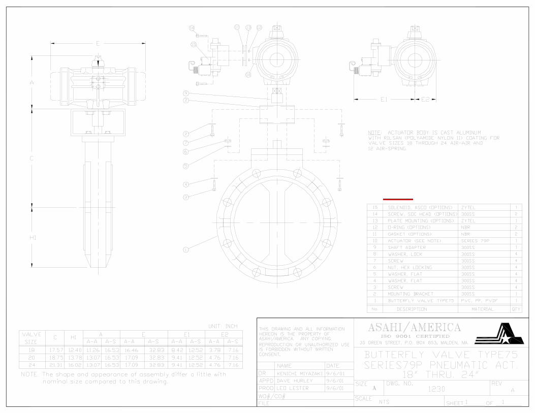
Type 75 Butterfly Valves Butterfly Valves (See Drawing #1230 sizes 18” - 24”) No specially machined stem or valve body drilling required. Remove gear operator by removing 4 thru bolts in body of valve to gear operator and lift off. Insert actuator shaft adapter #9 into actuator. Mount bracket #2 to actuator #10 using bolts #7 and washers #8. Install valve #1 to mounting bracket #2 using bolts #3, nuts #6, and washers #4, keeping in mind line scribed in valve stem indicates disc orientation before mounting and by flats on actuator shaft after mounting. CAUTION: If mounted unit is installed other than straight up, the actuator should be supported individually in order to prevent side loading and loosening up of fasteners.

ASAHI/AMERICA, INC 35 GREEN STREET MALDEN, MA. 02148 TELEPHONE 800-343-3618
File: Serie79p.MAN Location: Assembly/Manual Rev M April 1, 2006 Page 6 of 12
Operation
Single and Double Acting: Pressurized air is introduced via the bottom port and displaces two opposed pistons. When the pistons are displaced, they in turn rotate the actuator output shaft counterclockwise, which opens the valve. This action is the same for single acting and double acting actuators.
Single Acting: When the pressurized air is removed from the bottom port, the compressed springs located at the opposite side of the pistons relax. As the spring relax, they in turn rotate the actuator output shaft in a clockwise rotation, which closes the valve. Although the term “relax” is used, the springs are NEVER relaxed, and are ALWAYS under tension, so caution must be exercised.
Double Acting: When the pressurized air is removed from the bottom port, the unit remains in the same position until pressurized air is applied to the top port (unlike the single acting actuator). When the pressurized air is introduced to the top port, it is channeled to the opposite side of the pistons, driving them to their original position, which in turn rotates the actuator output shaft in a clockwise direction, closing the valve.
Optional Solenoid Valve (See drawing #004PNU) An optional solenoid valve (ASCO 8401 NAMUR mount) can be supplied mounted directly to the actuator. The cycling is accomplished by energizing the solenoid coil for one valve position (typically open), and de-energizing for the opposite valve position (typically closed). The unit is electrically fail safe; so it will return to its de-energized position on electrical failure, provided the air supply is not interrupted. The 8401 solenoid is equipped with speed controls, a manual override, and 18 inch long #18 AWG lead wire. The speed controls are needle valves that will reduce the CV value or increase the cycle time by creating back pressure within the actuator. Speed control adjustments are independent for the opening and closing strokes. Caution: If speed control adjustments are screwed in too far, actuator can not exhaust properly and will not cycle!! The manual override is engaged by pressing and rotating the red slotted screw clockwise 90 for the open position. Once the valve is open, simply rotate the red screw counter-clockwise 90 for the closed position. Caution: Manual override will not work without air supply!!

ASAHI/AMERICA, INC 35 GREEN STREET MALDEN, MA. 02148 TELEPHONE 800-343-3618
File: Serie79p.MAN Location: Assembly/Manual Rev M April 1, 2006 Page 7 of 12
Maintenance The Series 79P double rack and pinion actuators do not need any preventative maintenance. Periodic checks should be performed to ensure proper tightness of all fasteners. Caution: Isolate actuator from electrical power supply and compressed air supply before any maintenance is performed. Make sure both sides of pistons have been bled off.
Dis-assembly of Actuator
1. Place actuator in press and compress actuator. 2. When pressure is on end cap remove snap ring from groove. 3. Slowly release press, allowing springs to fully extend. 4. Remove end cap and springs 5. Repeat steps 1 through 4 for opposite end cap 6. Rotate shaft counter-clockwise to remove pistons. 7. Remove snap ring from shaft. 8. Slide shaft through actuator body and out the bottom.
Assembly of Actuator 1. Install shaft, washer, and secure with snap ring; making sure that the
snap ring is seated 2. With the air inlet ports facing you, install pistons into actuator body
with the rack of the right piston facing the air inlet ports. 3. Rotate shaft CCW (beyond open position) to engage both racks. Next,
rotate shaft CW to pull pistons to the closed fully position (actuator shaft should not be cocked, and there should be equal distance between the actuator body and the pistons).
4. Install desired number of springs and end cap to actuator body. 5. Compress springs with machine press 6. When end cap is in place, install snap ring; making sure that the snap
ring is seated 7. Slowly remove pressure from press to insure proper seating of end
cap. 8. Repeat steps 4 through 8 for other end.
CAUTION --- DANGER!!!!!!! Failure to use proper tools can result in SERIOUS INJURY! The actuator springs are very strong and are compressed whenactuator is assembled. A machine press (not a vise), customfixture, and proper tools are required to disassemble actuator.

ASAHI/AMERICA, INC 35 GREEN STREET MALDEN, MA. 02148 TELEPHONE 800-343-3618
File: Serie79p.MAN Location: Assembly/Manual Rev M April 1, 2006 Page 8 of 12
Repair Kits
NOTE: When ordering replacement actuator parts and/or options specify model # and voltage.
Actuator Model Part Number Actuator Model Part Number A79P 2398001 D79P 2398020 B79P 2398000 D579P 2398025 B579P 2398005 E79P 2398030 C79P 2398010 F79P 2398040 C579P 2398015 G79P 2398050
Each repair kit includes the following (Please reference exploded views)
Description Item Number 1 set of piston o-rings 11 1 set of piston guides 9 1 set of guide rings 10 1 set of end cap o-rings 3 1 set of upper shaft o-rings 12 1 set of lower shaft o-rings 13 1 shaft washer 6 1 shaft snap ring 7

ASAHI/AMERICA, INC 35 GREEN STREET MALDEN, MA. 02148 TELEPHONE 800-343-3618
File: Serie79p.MAN Location: Assembly/Manual Rev M April 1, 2006 Page 9 of 12
Engineering Data
Actuators
Solenoids All solenoid coils may be used at +10% to -10% of rated voltages. Coils are 50/60 Hertz and are rated for continuous duty if operated at 60 Hertz. Note: Consult factory for non-standard voltages and for continuous duty at 50 Hertz.
Rated Voltage In Rush Current Milliamp @ 60 Hz
Holding Current Milliamp @ 60 Hz
Watts @ Rated Voltages
120 VAC 113 71 6.2 24 VAC 566 360 6.2 240 VAC 56 35 6.2 12 VDC --- 583 7 24 VDC --- 292 7
Solenoids are furnished with 18 inch long #18 AWG lead wire. Attachments: 8 drawings: 0114BV, 0115BV, 0139BV, 0167BF, 0167BF57, 0204BF57 1230, 0004PNU.
AIR CONSUMPTION (CUBIC INCHES)
Air to Air Air to SpringModel No. Open
Port A Close Port B Air Stroke
A79P 4.58 3.05 4.58 B79P 9.15 6.1 9.15 B579P 17 15.25 17 C79P 21.35 19.52 21.35 C579P 39.66 33.56 39.66 D79P 48.82 42.72 48.82 D579P 91.54 79.33 91.54 E79P 125.1 115.95 125.1 F79P 323.43 219 323.43 G79P 640.75 427.17 640.75
CYCLE TIME (SECONDS PER STROKE)
Air to Air Air to Spring Model No. Open
Port AClose Port B
Open Port A
Close Port B
A79P 0.10 0.10 0.15 0.30 B79P 0.15 0.15 0.20 0.40
B579P 0.20 0.20 0.40 0.80 C79P 0.25 0.25 0.60 1.10
C579P 0.30 0.30 1.00 1.50 D79P 0.40 0.40 1.70 2.00
D579P 0.50 0.50 2.70 3.90 E79P 0.60 0.60 3.80 5.50 F79P 1.20 1.20 5.80 12.00G79P 2.00 2.00 18.20 19.00
NOTE: Actuator supplied with 80 psi, and l d

ASAHI/AMERICA, INC 35 GREEN STREET MALDEN, MA. 02148 TELEPHONE 800-343-3618
File: Serie79p.MAN Location: Assembly/Manual Rev M April 1, 2006 Page 10 of 12
Exploded Views
A79, B79, & B579
* Not used on A79 Actuators
No Description Qty Material
1 End Cap Retaining Ring 2 Cataphoresis Coated Steel 2 Double Acting End Cap 2 See Note for Material 3 End Cap O-Ring 2 NBR 4 Piston 2 Polyarilamide 5 Actuator Body 1 See Note for Material 6 Washer 1 Polyamide 6
7 Shaft Retaining Ring
1 Stainless Steel for A79 Nickel PTFE Coated Steel for B79 & B579
8 Position Indicator 1 Polyacetal for A79 - Polyamide for B79 & B579
9 Piston Guide* 2 Polyacetal 10 Guide Ring 2 Polyacetal 11 Piston O-Ring 2 NBR 12 Upper Shaft O-Ring 2 NBR 13 Lower Shaft O-Ring 2 NBR 14 Spring Set 1 Cataphoresis Coated DIN-17223-C 15 Spring Return End Cap 2 See Note for Material 16
Shaft 1 303 Stainless Steel - B79 & B579 Polyamide
with 303 SS Insert

ASAHI/AMERICA, INC 35 GREEN STREET MALDEN, MA. 02148 TELEPHONE 800-343-3618
File: Serie79p.MAN Location: Assembly/Manual Rev M April 1, 2006 Page 11 of 12
C79, C579, D79, & D579
No Description Qty Material
1 End Cap Retaining Ring 2 Cataphoresis Coated Steel
2 Double Acting End Cap 2 See Note for Material 3 End Cap O-Ring 2 NBR
4 Piston 2 Polyarilamide
5 Actuator Body 1 See Note for Material
6 Washer 1 Polyamide 6
7 Shaft Retaining Ring 1 Nickel PTFE Coated Steel
8 Position Indicator 1 Polyamide
9 Piston Guide 2 Polyacetal
10 Guide Ring 2 Polyacetal
11 Piston O-Ring 2 NBR
12 Upper Shaft O-Ring 2 NBR
13 Lower Shaft O-Ring 2 NBR
14 Spring Set 1 Cataphoresis Coated DIN-17223-C
15 Spring Return End Cap 2 See Note for Material 16 Shaft 1 303 Stainless Steel for C79, C579 & D79
Cataphoresis Coated Steel for D579
17 Pinion Gear 1 Cataphoresis Coated Aluminum Alloy
ASAHI/AMERICA, INC 35 GREEN STREET MALDEN, MA. 02148 TELEPHONE 800-343-3618
File: Serie79p.MAN Location: Assembly/Manual Rev M April 1, 2006 Page 12 of 12
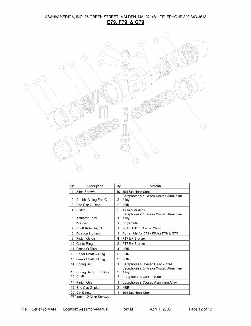
E79, F79, & G79
No Description Qty Material
1 Allen Screw* 16 304 Stainless Steel
2 Double Acting End Cap 2 Cataphoresis & Rilsan Coated Aluminum Alloy
3 End Cap O-Ring 2 NBR 4 Piston 2 Aluminum Alloy
5 Actuator Body 1 Cataphoresis & Rilsan Coated Aluminum Alloy
6 Washer 1 Polyamide 6 7 Shaft Retaining Ring 1 Nickel PTFE Coated Steel 8 Position Indicator 1 Polyamide for E79 - PP for F79 & G79 9 Piston Guide 4 PTFE + Bronze
10 Guide Ring 2 PTFE + Bronze 11 Piston O-Ring 4 NBR 12 Upper Shaft O-Ring 2 NBR 13 Lower Shaft O-Ring 2 NBR 14 Spring Set 1 Cataphoresis Coated DIN-17223-C
15 Spring Return End Cap 2 Cataphoresis & Rilsan Coated Aluminum Alloy
16 Shaft 1 Cataphoresis Coated Steel
17 Pinion Gear 1 Cataphoresis Coated Aluminum Alloy 19 End Cap Gasket 2 NBR 20 Set Screw 1 304 Stainless Steel
* E79 uses 12 Allen Screws

KMiyazaki
FOR REFERENCE ONLY ASAHI/AMERICA

KMiyazaki
FOR REFERENCE ONLY ASAHI/AMERICA

KMiyazaki
FOR REFERENCE ONLY ASAHI/AMERICA
KMiyazaki
FOR REFERENCE ONLY ASAHI/AMERICA

KMiyazaki
FOR REFERENCE ONLY ASAHI/AMERICA

KMiyazaki
FOR REFERENCE ONLY ASAHI/AMERICA

KMiyazaki
FOR REFERENCE ONLY ASAHI/AMERICA