ASA-CR-201983 ATOMIZATION SIMULATIONS … ATOMIZATION SIMULATIONS USING AN EULERIAN-VOF-LAGRANGIAN...
12
_ASA-CR-201983 ATOMIZATION SIMULATIONS USING AN EULERIAN-VOF-LAGRANGIAN METHOD _, r -, /, Yen-Sen Chen, Huan-Min Shang and Paul Liaw Engineering Sciences, Inc. Huntsville, AL 35802 C. P. Chen University of Alabama in Huntsville Huntsville, AL 35899 ABSTRACT This paper summarizes the technical development and validation of a multiphase computational fluid dynamics (CFD) numerical method using the volume-of-fluid (VOF) model and a Lagrangian tracking model which can be employed to analyze general multiphase flow problems with free surface mechanism. The gas-liquid interface mass, momentum and energy conservations are modeled by continuum surface mechanisms. A new solution method is developed such that the present VOF model can be applied for all-speed flow regimes. The objectives of the present study are to develop and verify the fractional volume-of-fluid cell partitioning approach into a predictor-corrector algorithm and to demonstrate the effectiveness of the present innovative approach by simulating benchmark problems including the coaxial jet atomization. INTRODUCTION The atomization and breakup processes of liquid fuel in many space transportation and propulsion systems are of vital importance to combustion performance and stability. Numerical modeling of these flows poses a significant challenge because it requires simultaneous resolutions of transient liquid-gas-droplets dynamics, and the flow regimes considered can range from incompressible to high-speed compressible flows. The flow-process modeling is further complicated by surface tension, interfacial heat and mass transfer, material property variation, spray formation and turbulence, and their interactions. It is the aim of this study that a general and robust design analysis tool will be available as a result of the incorporation of advanced numerical and physical models in a computational fluid dynamics flow solver. Historically, developments of numerical methods for multiphase free surface flows were primarily aimed at incompressible flows utilizing the Volume of Fluid (VOF) method. [1,2]. These methods are often ineffective for high-speed, high-Reynolds-number flows. So far, multiphase free surface flows have not been considered in more general all-speed flow algorithms, with only a few recent exceptions [3,4,5]. In the ARICC-3D Code [3], the VOF method was implemented in the ALE-ICE (Arbitrary Lagrangian Eulerian-Implicit Continuous- fluid Eulerian method) algorithm for injector flow simulation with atomization. Due to the inefficiency of the ALE-ICE method, the ARICC-3D was found very time-consuming for multi- • This work was sponsored by NASA-MSFC with Dr. T.S. Wang as technical monitor under contract NAS8-40148. Approval for public release; distribution is unlimited. https://ntrs.nasa.gov/search.jsp?R=19960049629 2018-07-07T03:15:28+00:00Z
Transcript of ASA-CR-201983 ATOMIZATION SIMULATIONS … ATOMIZATION SIMULATIONS USING AN EULERIAN-VOF-LAGRANGIAN...
_ASA-CR-201983
ATOMIZATION SIMULATIONS USING
AN EULERIAN-VOF-LAGRANGIAN METHOD
_, r -, /,
Yen-Sen Chen, Huan-Min Shang and Paul Liaw
Engineering Sciences, Inc.Huntsville, AL 35802
C. P. Chen
University of Alabama in Huntsville
Huntsville, AL 35899
ABSTRACT
This paper summarizes the technical development and validation of a multiphase
computational fluid dynamics (CFD) numerical method using the volume-of-fluid (VOF) model
and a Lagrangian tracking model which can be employed to analyze general multiphase flow
problems with free surface mechanism. The gas-liquid interface mass, momentum and energyconservations are modeled by continuum surface mechanisms. A new solution method is
developed such that the present VOF model can be applied for all-speed flow regimes. The
objectives of the present study are to develop and verify the fractional volume-of-fluid cell
partitioning approach into a predictor-corrector algorithm and to demonstrate the effectiveness of
the present innovative approach by simulating benchmark problems including the coaxial jetatomization.
INTRODUCTION
The atomization and breakup processes of liquid fuel in many space transportation andpropulsion systems are of vital importance to combustion performance and stability. Numerical
modeling of these flows poses a significant challenge because it requires simultaneous
resolutions of transient liquid-gas-droplets dynamics, and the flow regimes considered can range
from incompressible to high-speed compressible flows. The flow-process modeling is further
complicated by surface tension, interfacial heat and mass transfer, material property variation,
spray formation and turbulence, and their interactions. It is the aim of this study that a general
and robust design analysis tool will be available as a result of the incorporation of advanced
numerical and physical models in a computational fluid dynamics flow solver.
Historically, developments of numerical methods for multiphase free surface flows were
primarily aimed at incompressible flows utilizing the Volume of Fluid (VOF) method. [1,2].These methods are often ineffective for high-speed, high-Reynolds-number flows. So far,
multiphase free surface flows have not been considered in more general all-speed flowalgorithms, with only a few recent exceptions [3,4,5]. In the ARICC-3D Code [3], the VOF
method was implemented in the ALE-ICE (Arbitrary Lagrangian Eulerian-Implicit Continuous-fluid Eulerian method) algorithm for injector flow simulation with atomization. Due to the
inefficiency of the ALE-ICE method, the ARICC-3D was found very time-consuming for multi-
• This work was sponsored by NASA-MSFC with Dr. T.S. Wang as technical monitor under contractNAS8-40148. Approval for public release; distribution is unlimited.
https://ntrs.nasa.gov/search.jsp?R=19960049629 2018-07-07T03:15:28+00:00Z
elementcomputations.Recently,theALE-ICEmethodwasabandonedbythecodedeveloperinfavorof thepressure-basedSIMPLEalgorithm[4]. In theRIPPLEcomputerprogram[5], onlyfinite difference solutions to the incompressible Navier-Stokes equation are obtained on an
Eulerian, rectangular mesh using a time-split two-step projection algorithm. Compressible fluidswere not solved, while the surface tension is treated using a novel continuum surface force (CSF)model.
Based on a preliminary study presented last year [16], a unified multi-phase numerical
method is developed. The gas-liquid interface mass, momentum and energy conservation
properties are modeled by continuum surface mechanisms. A new solution method is developed
such that the present VOF model can be applied for all-speed range flows. The objectives of the
present study are: (a) to develop and verify the fractional volume-of-fluid (VOF) cell
partitioning approach into a predictor-corrector algorithm to deal with multiphase (gas-liquid)
free surface flow problems; (b) to implement the developed unified algorithm in a general
purpose computational fluid dynamics (CFD) code, Finite Difference Navier-Stokes (FDNS),
with numerical treatment of droplet dynamics models described in [6].
The main feature of the present method is to combine the novel feature of the Volume of
Fluid (VOF) method and the Eulerian/Lagrangian method used in a pressure-based particulate
two-phase flow solver [6, 9, 10] into a unified algorithm for efficient non-iterative, time-accuratecalculations of multiphase free surface flows valid at all speeds. The proposed method
reformulated the VOF equation to strongly couple two distinct phases (liquid and gas), and tracks
droplets on a Lagrangian frame when spray model is required, using a unified predictor-corrector
technique to account for the non-linear linkages through the convective contributions of VOF.
The discontinuities within the sharp interface will be modeled as a volume force to avoid
stiffness. Formations of droplets and tracking of droplet dynamics are handled through the same
unified predictor-corrector procedure. Thus the new algorithm is non-iterative and is flexible in
the handling of any general geometries with arbitrarily complex topology in free surfaces. The
present method can also be applied for efficient steady state situations and can be implemented
into any pressure-based methodology. For the purpose of algorithm development and validation,
the proposed method will be implemented into a general purpose CFD code, Finite DifferenceNavier-Stokes FDNS [9,10], which has three dimensional and multi-zone capabilities.
METHODOLOGY
Governing Equation
Conventionally, there have been some successful numerical algorithms for performing
multiphase flow calculations involving free interfaces. In general, two basic approaches can beidentified. One is based on the Lagrangian method and the other on the Eulerian frame work.
The Lagrangian approach is to conform a mesh system with the sharp interface between gas and
liquid and to track the movement of the interface according to sets of simplified equations
governing the liquid and gas motions separately [8]. The entire Lagrangian grid network moveswith the free surface which makes the grid generation or remeshing procedure very complex and
CPU intensive. In the Eulerian approach, a fixed mesh system is used to resolve the sharp
interface by the concept of a fractional volume of fluid (VOF) [11 ]. The second approach ismore flexible and efficient in that it allows the resolution of the free surface to become part of
the solution. The physical processes across the sharp interface such as surface tension forces,
droplet or wave breakup, interphase mass transfer and condensation/vaporization, etc. can bemodeled through the concept of continuum surface force (CSF) method [7] or by the method of
surfacereconstructionasusedin the ARICC3Dcode [4], SOLA-VOFcode [1]. The CSFmethodis adoptedin thepresentmodelfor itsgeneralityandcomputationalefficiency,especiallyfor 3-dimensionalcomputations.
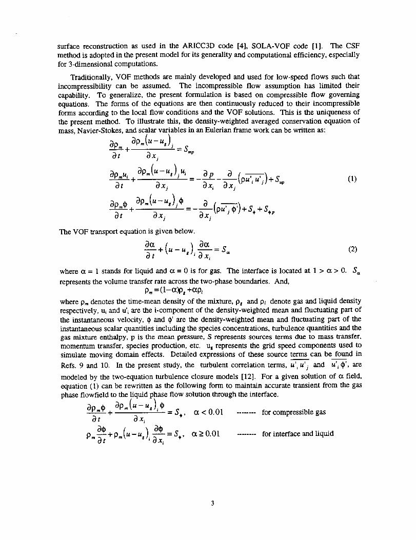
Traditionally,VOF methodsaremainlydevelopedandusedfor low-speedflows suchthatincompressibilitycan be assumed. The incompressibleflow assumptionhas limited theircapability. To generalize,the presentformulationis basedon compressibleflow governingequations.Theformsof the equationsarethencontinuouslyreducedto their incompressibleformsaccordingto the local flow conditionsandtheVOF solutions.This is theuniquenessofthepresentmethod.To illustratethis,thedensity-weightedaveragedconservationequationofmass,Navier-Stokes,andscalarvariablesin anEulerianframeworkcanbe written as:
ap=(u-u_ljapm _. =S._at ax)
ap... a0.(u-.,),., a <,>_d" -"
at ax_ ax_ ax_
(u \
ap. ),* a +s.,ap., + -u, =_mat axj ax_
The VOF transport equation is given below.
a(x (u-27,+ - ax--7=where ct = 1 stands for liquid and ct = 0 is for gas. The interface is located at 1 > ct > O. S,,
represents the volume transfer rate across the two-phase boundaries. And,
p. = (1-a)pg +c_pt
where p,, denotes the time-mean density of the mixture, pg and p_ denote gas and liquid density
respectively, u_ and u', are the i-component of the density-weighted mean and fluctuating part of
the instantaneous velocity, ¢ and 0' are the density-weighted mean and fluctuating part of the
instantaneous scalar quantifies including the species concentrations, turbulence quantities and thegas mixture enthalpy, p is the mean pressure, S represents sources terms due to mass transfer,
momentum transfer, species production, etc. uz represents the grid speed components used to
simulate moving domain effects. Detailed expressions of these source terms can be found in-- I I l
Refs. 9 and 10. In the present study, the turbulent correlation terms, u _u j and u _(_', are
modeled by the two-equation turbulence closure models [12]. For a given solution of (x field,
equation (1) can be rewritten as the following form to maintain accurate transient from the gas
phase flowfield to the liquid phase flow solution through the interface.
ap., += S,, ot < O. 01 ........ for compressible gas
at axi
p _-_-_+p.(u-u,), a----_--_=s,, o_>_O.Ot ........ for interface and nquiddt ax i
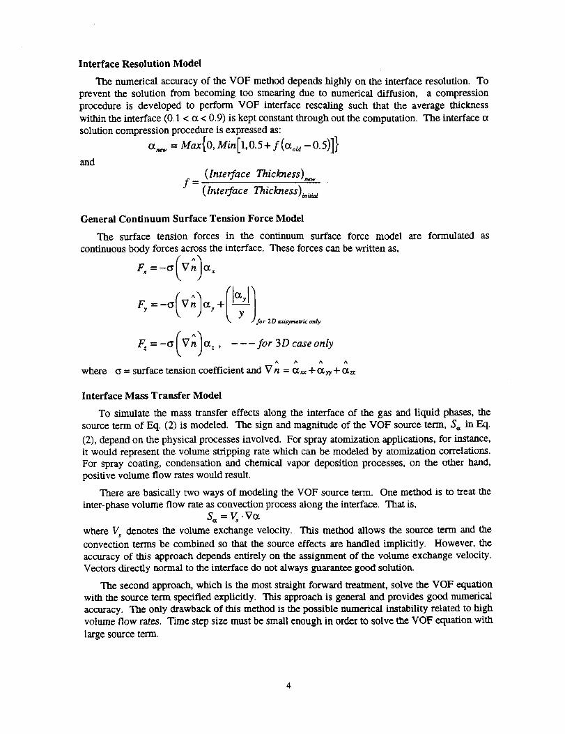
Interface Resolution Model
The numerical accuracy of the VOF method depends highly on the interface resolution. To
prevent the solution from becoming too smearing due to numerical diffusion, a compression
procedure is developed to perform VOF interface rescaling such that the average thickness
within the interface (0.1 < o_< 0.9) is kept constant through out the computation. The interface et
solution compression procedure is expressed as:
a,,_ = Max{O, Min[l,O.5+ f(o_ou-0.5)]}
and
(Interface Thickness).,,,,f=
(Interface Thickness)_,iaa
General Continuum Surface Tension Force Model
The surface tension forces in the continuum surface force model
continuous body forces across the interface. These forces can be written as,
F,=-_ Vn %+ _
.for 2 D _mr_,_: only
(AIF_=-a Vn or,, --- for 3Dcaseonly
A A A A
where _ = surface tension coefficient and V n = {x_, + O_ry+ {z=
are formulated as
Interface Mass Transfer Model
To simulate the mass transfer effects along the interface of the gas and liquid phases, the
source term of Eq. (2) is modeled. The sign and magnitude of the VOF source term, S_, in Eq.
(2), depend on the physical processes involved. For spray atomization applications, for instance,
it would represent the volume stripping rate which can be modeled by atomization correlations.For spray coating, condensation and chemical vapor deposition processes, on the other hand,
positive volume flow rates would result.
There are basically two ways of modeling the VOF source term. One method is to treat the
inter-phase volume flow rate as convection process along the interface. That is,
where V, denotes the volume exchange velocity. This method allows the source term and the
convection terms be combined so that the source effects are handled implicitly. However, the
accuracy of this approach depends entirely on the assignment of the volume exchange velocity.
Vectors directly normal to the interface do not always guarantee good solution.
The second approach, which is the most straight forward treatment, solve the VOF equation
with the source term specified explicitly. This approach is general and provides good numerical
accuracy. The only drawback of this method is the possible numerical instability related to high
volume flow rates. Time step size must be small enough in order to solve the VOF equation with
large source term.
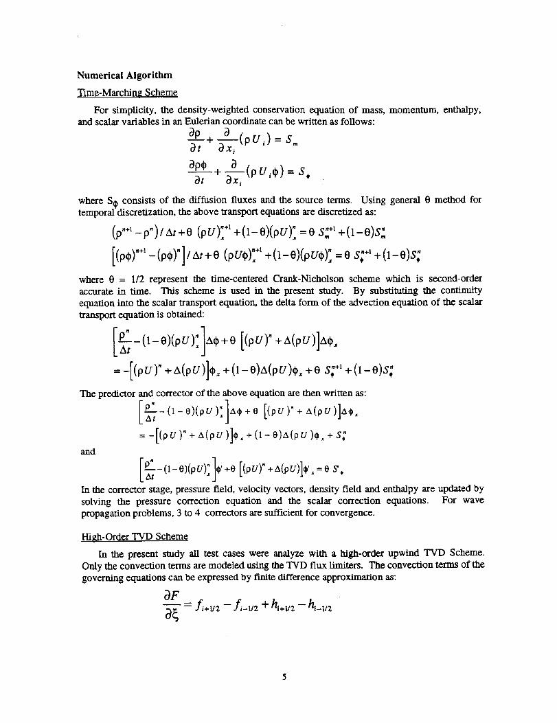
Numerical Algorithm
Time-Marching Scheme
For simplicity, the density-weighted conservation equation of mass, momentum, enthalpy,and scalar variables in an Eulerian coordinate can be written as follows:
0p+0t 0--_/(pU. ' ) = S=
_P--"_"÷_t -_/(pU/_p). = S¢
where S0 consists of the diffusion fluxes and the source terms. Using general 0 method fortemporal discretization, the above transport equations are discretized as:
(p..l_p.)/At+O, """*1 S: ÷_ (1-0)S:LOU), +(1-O)(pU)] =O +
[(p))"+'-(p))']/At +0 (pUO): +' +(1-0)(pU(_); =0 S: +; + (1-0)S:
where 0 = 1/2 represent the time-centered Crank-Nicholson scheme which is second-orderaccurate in time. This scheme is used in the present study. By substituting the continuity
equation into the scalar transport equation, the delta form of the advection equation of the scalar
transport equation is obtained:
[° ]y-0-o)(pv); a,+o [(0v)'+a(pvl]a,,
=-[(pU)" + A(pU)]O, + (1-O)A(pU)q), +0 _,,¢"+'+ (1- O)S:
The predictor and corrector of the above equation are then written as:
-E;-(_-e)(ou), ,x,),+o[(_,v)"+,,(or)],,,),,
=-[(pu )'+ ,,,(pu )],, +(_-o),x(pu ),, +s:and
,i ]0+o + oIn the corrector stage, pressure field, velocity vectors, density field and enthalpy are updated by
solving the pressure correction equation and the scalar correction equations. For wave
propagation problems, 3 to 4 correctors are sufficient for convergence.
High-Order TVD Scheme
In the present study all test cases were analyze with a high-order upwind TVD Scheme.
Only the convection terms are modeled using the TVD flux Umiters. The convection terms of the
governing equations can be expressed by finite difference approximation as:
0F-,'--;- = f _+u2 - f _-,,2 + h,+t/2 - hz-u2_a
where f and h represent first-order fluxes and TVD flux limiters respectively. The TVD flux
limiters are functioned as anti-diffusion terms to recover the scheme to high-order accuracy. Thefirst-order fluxes and the TVD flux Umiters are given below.
f,÷1,2 = max {0,(pU ),.,,2 }q_, + max {0,-(pU ),+1,_}_,_
{¼1pu I,+,,={d,,*.,,2+ += >_0hi+ll 2 =
+dO,L3, + <0where the minmod functions in the TVD flux limiters are written as:
d¢_+_,: = sign (m(_i+x,2) max{0,min[IAqb,+_/: ,_ sign (Aqb,+_/:)A_,+l/:_ ]}
The order of accuracy of this scheme is determined by the parameters ¢x and _. Only the second-
order and third-order upwind schemes were used in this study. That is,
Ct=I-l_ 2nd-order upwind
.|+3' 3rd- order upwind
3 - o_= Compression - Factor=
1- t_
The compression factor. 13,is used to sharpen the contact discontinuities and slip streams for
better wave tracking.
VALIDATIONS
Microgravity Fluid Tank Test Cases
To validate the present VOF method within the compressible and incompressible flowsolver, some fluid tank benchmark test cases were investigated and compared with close form
solutions. The key mechanisms involved here are the surface tension forces and the effects of
wall contact angle. The liquid surface tension forces are modeled using the proposed continuumsurface force (CSF) model and the wall contact angles are provided by the material properties
and through the use of Young' s equation.
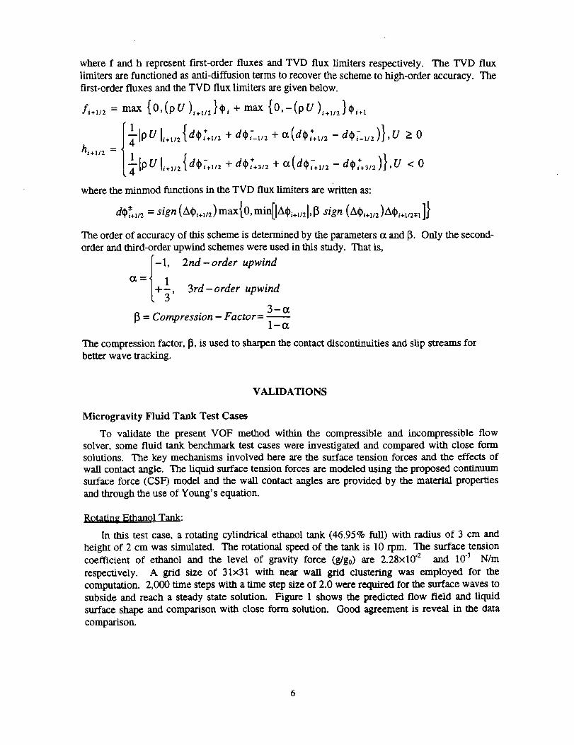
Rotating Ethanol Tank:
In this test case, a rotating cylindrical ethanol tank (46.95% full) with radius of 3 cm and
height of 2 cm was simulated. The rotational speed of the tank is 10 rpm. The surface tensioncoefficient of ethanol and the level of gravity force (g/g0) are 2.28x10 "2 and 10.3 N/m
respectively. A grid size of 31x31 with near wall grid clustering was employed for the
computation. 2,000 time steps with a time step size of 2.0 were required for the surface waves to
subside and reach a steady state solution. Figure 1 shows the predicted flow field and liquid
surface shape and comparison with close form solution. Good agreement is reveal in the data
comparison.
° .......
• . . ° ° • ....
, ° ........
• , ° .......
Y (cm)
• ar"cm 3 IE:_
Figure 1. Rotating ethanol tank: 10 .3 go and 10 rpm.
I
I. sr_e 2_41
R (m)
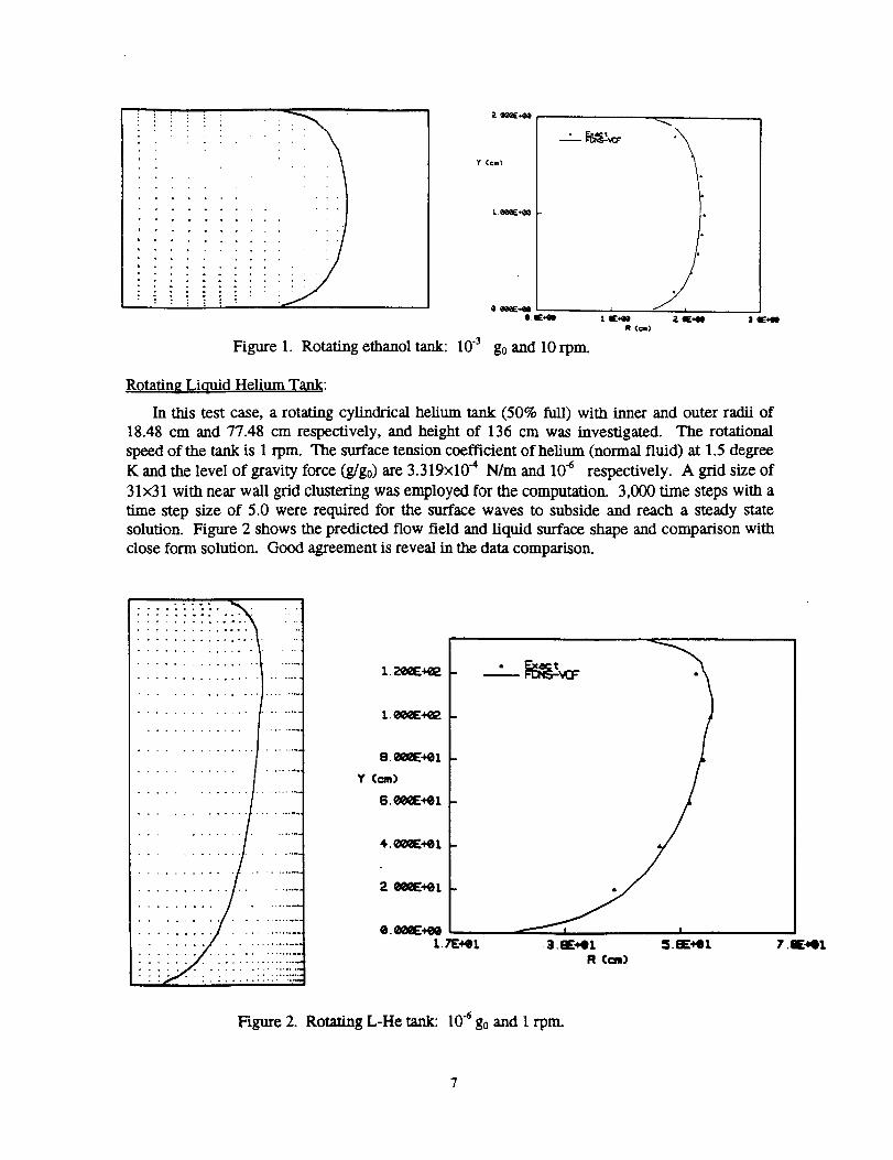
Rotating Liquid Helium Tank:
In this test case, a rotating cylindrical helium tank (50% full) with inner and outer radii of
18.48 cm and 77.48 cm respectively, and height of 136 cm was investigated. The rotational
speed of the tank is 1 rpm. The surface tension coefficient of helium (normal fluid) at 1.5 degree
K and the level of gravity force (g/g0) are 3.319x10 4 N/m and 106 respectively. A grid size of
31x31 with near wall grid clustering was employed for the computation. 3,000 time steps with a
time step size of 5.0 were required for the surface waves to subside and reach a steady state
solution. Figure 2 shows the predicted flow field and liquid surface shape and comparison withclose form solution. Good agreement is reveal in the data comparison.
Figure 2.
8._+el
Y (cm)
S._+el
2 (_E:+GI
e. _lQE+eet.TE+et 3. gr, et _S._:s=.tQ1 7 .IE:._l
R (cm)
Rotating L-He tank: 10.4 go and 1 rpm.
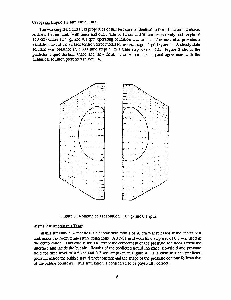
Cryogenic Liquid Helium Fluid Tank:
The working fluid and fluid properties of this test case is identical to that of the case 2 above.
A dewar helium tank (with inner and outer radii of 12 cm and 70 cm respectively and height of150 cm) under 10 -7 go and 0.1 rpm operating condition was tested. This case also provides a
validation test of the surface tension force model for non-orthogonal grid systems. A steady state
solution was obtained in 3,000 time steps with a time step size of 5.0. Figure 3 shows the
predicted liquid surface shape and flow field. This solution is in good agreement with the
numerical solution presented in Ref. 14.
. ° - ° ° °
• . ..... Q,.m
° ° • ° . ..... ,••,l
° °
• . ° ...... .lo
i : i .........
!!!!!i!ilil
i ......... ° ° ° • • ° ° • • •
'*4, ..... • • ° • • ...
• • ...
......... :iii
Figure 3. Rotating dewar solution: 10 "7 go and 0.l rpm.
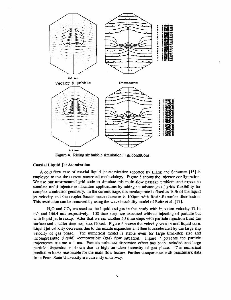
Ri_ing Air Bul_l_l¢ in _ Tank:
In this simulation, a spherical air bubble with radius of 20 cm was released at the center of a
tank under lg0 room temperature conditions. A 31x31 grid with time step size of 0.1 was used in
the computation. This case is used to check the correctness of the pressure solutions across the
interface and inside the bubble. Results of the predicted liquid interface, flowfield and pressure
field for time level of 0.5 sec and 0.7 sec are given in Figure 4. It is clear that the predicted
pressure inside the bubble stay almost constant and the shape of the pressure contour follows that
of the bubble boundary. This simulation is considered to be physically correct.
.... ii I iii..
0.$ sec
Vector 8.Bubble
......... , 0........... ..
0.7 _
Pressure
Figure 4. Rising air bubble simulation: lg0 conditions.
i I _-41
I _!77ll-41
t _'-Ot1 _ m[-.Ott .-O1
I _-41I 141I aD'q:-41
• t _-'@t
. II_l
I :_I_ !-'01
Coaxial Liquid Jet Atomization
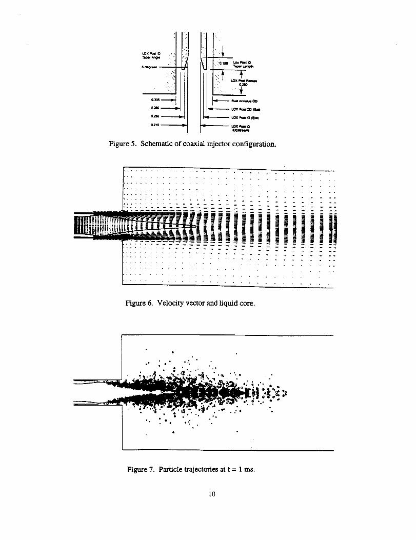
A cold flow case of coaxial liquid jet atomization reported by Liang and Schuman [15] is
employed to test the current numerical methodology. Figure 5 shows the injector configuration.
We use our unstructured grid code to simulate this multi-flow passage problem and expect to
simulate multi-injector combustion applications by taking its advantage of grids flexibility for
complex combustor geometry. In the current stage, the breakup rate is fixed as 10% of the liquid
jet velocity and the droplet Sauter mean diameter is 100_trn with Rosin-Rammler distribution.
This restriction can be removed by using the wave instability model of Reitz et al. [17].
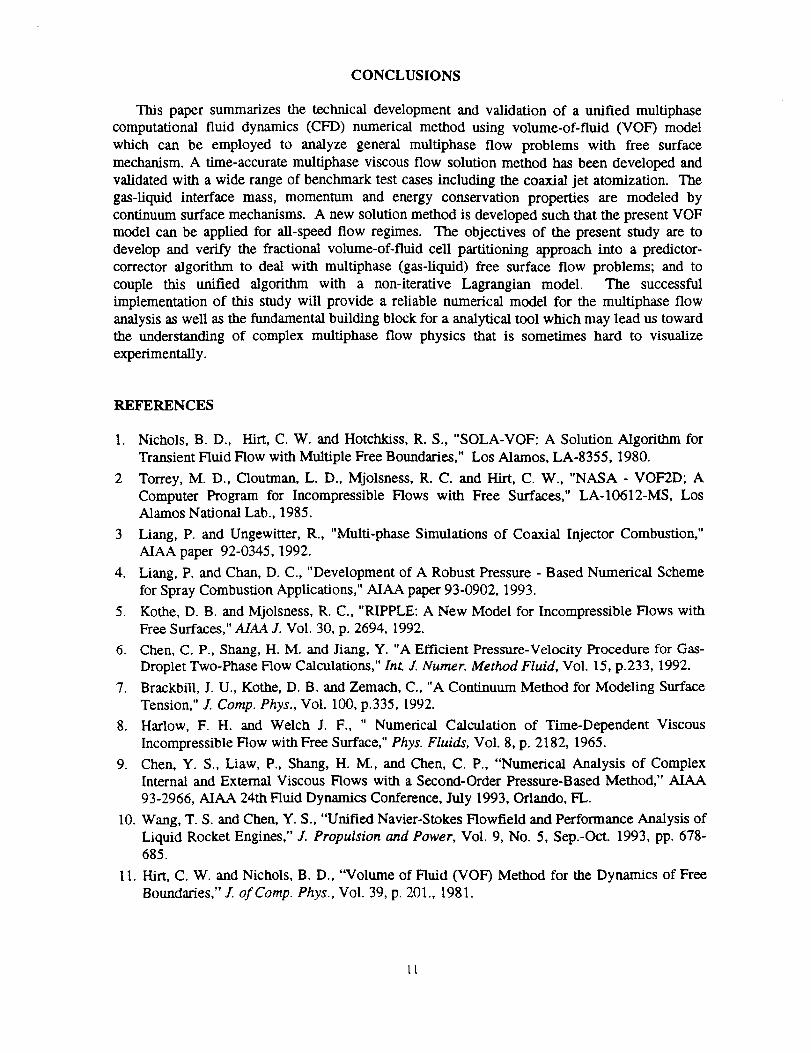
H20 and CO2 are used as the liquid and gas in this study with injection velocity 12.14
m/s and 166.4 m/s respectively. 100 time steps are executed without injecting of particle but
with liquid jet breakup. After that we ran another 50 time steps with particle injection from the
surface and smaller time-step size (20_). Figure 6 shows the velocity vectors and liquid core.
Liquid jet velocity decreases due to the nozzle expansion and then is accelerated by the large slip
velocity of gas phase. The numerical model is stable even for large time-step size and
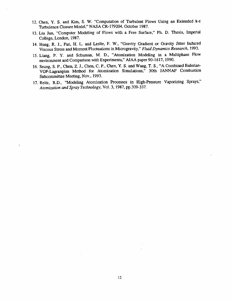
incompressible (liquid) /compressible (gas) flow situation. Figure 7 presents the particletrajectories at time = 1 ms. Particle turbulent dispersion effect has been included and large
particle dispersion is shown due to high turbulent intensity of gas phase. The numerical
prediction looks reasonable for the main flow feature. Further comparisons with benchmark data
from Penn. State University are currently underway.
e_ ,:i!.
Figure 5. Schematic of coaxial injector configuration.
................... .. - 2 2 - -_ "2 _ "2 "2"2
• . . o . ,
Figure 6. Velocity vector and liquid core.
Figure 7. Particle trajectories at t = 1 ms.
t0
CONCLUSIONS
This paper summarizes the technical development and validation of a unified multiphase
computational fluid dynamics (CFD) numerical method using volume-of-fluid (VOF) model
which can be employed to analyze general multiphase flow problems with free surfacemechanism. A time-accurate multiphase viscous flow solution method has been developed and
validated with a wide range of benchmark test cases including the coaxial jet atomization. The
gas-liquid interface mass, momentum and energy conservation properties are modeled by
continuum surface mechanisms. A new solution method is developed such that the present VOF
model can be applied for all-speed flow regimes. The objectives of the present study are to
develop and verify the fractional volume-of-fluid cell partitioning approach into a predictor-
corrector algorithm to deal with multiphase (gas-liquid) free surface flow problems; and to
couple this unified algorithm with a non-iterative Lagrangian model. The successful
implementation of this study will provide a reliable numerical model for the multiphase flow
analysis as well as the fundamental building block for a analytical tool which may lead us toward
the understanding of complex multiphase flow physics that is sometimes hard to visualize
experimentally.
REFERENCES
1. Nichols, B. D., Hirt, C. W. and Hotchkiss, R. S., "SOLA-VOF: A Solution Algorithm for
Transient Fluid Flow with Multiple Free Boundaries," Los Alamos, LA-8355, 1980.
2 Torrey, M. D., Cloutman, L. D., Mjolsness, R. C. and HArt, C. W., "NASA - VOF2D; A
Computer Program for Incompressible Flows with Free Surfaces," LA-10612-MS, LosAlamos National Lab., 1985.
3 Liang, P. and Ungewitter, R., "Multi-phase Simulations of Coaxial Injector Combustion,"
AIAA paper 92-0345, 1992.
4. Liang, P. and Chan, D. C., "Development of A Robust Pressure - Based Numerical Scheme
for Spray Combustion Applications," AIAA paper 93-0902, 1993.
5. Kothe, D. B. and Mjolsness, R. C., "RIPPLE: A New Model for Incompressible Flows with
Free Surfaces," A/AA J. Vol. 30, p. 2694, 1992.
6. Chert, C. P., Shang, H. M. and Jiang, Y. "A Efficient Pressure-Velocity Procedure for Gas-
Droplet Two-Phase Flow Calculations," Int. Z Numer. Method Fluid, Vol. 15, p.233, 1992.
7. Brackbill, J. U., Kothe, D. B. and Zemach, C., "A Continuum Method for Modeling Surface
Tension," J. Comp. Phys., Vol. 100, p.335, 1992.
8. Haxlow, F. H. and Welch J. F., " Numerical Calculation of Time-Dependent Viscous
Incompressible Flow with Free Surface," Phys. Fluids, Vol. 8, p. 2182, 1965.
9. Chen, Y. S., Liaw, P., Shang, H. M., and Chen, C. P., "Numerical Analysis of ComplexInternal and External Viscous Flows with a Second-Order Pressure-Based Method," AIAA
93-2966, AIAA 24th Fluid Dynamics Conference, July 1993, Orlando, FL.
10. Wang, T. S. and Chert, Y. S., "Unified Navier-Stokes Flowfield and Performance Analysis of
Liquid Rocket Engines," J. Propulsion and Power, Vol. 9, No. 5, Sep.-Oct. 1993, pp. 678-685.
11. Hirt, C. W. and Nichols, B. D., "Volume of Fluid (3/O1") Method for the Dynamics of Free
Boundaries," J. of Comp. Phys., Vol. 39, p. 201, 1981.
tt
12.Chen,Y. S. and Kim, S.W. "Computationof Turbulent Flows Using an Extended k-eTurbulence Closure Model," NASA CR-179204, October 1987.
13. Liu Jun, "Computer Modeling of Flows with a Free Surface," Ph.D. Thesis, Imperial
College, London, 1987.
14. Hung, R. J., Pan, H. L. and Leslie, F. W., "Gravity Gradient or Gravity Jitter InducedViscous Stress and Moment Fluctuations in Microgravity," Fluid Dynamics Research, 1993.
15. Liang, P. Y. and Schuman, M. D., "Atomization Modeling in a Multiphase Flow
environment and Comparison with Experiments," AIAA paper 90-1617, 1990.
16. Seung, S. P., Chen, Z. J., Chen, C. P., Chen, Y. S. and Wang, T. S., "A Combined Eulerian-
VOF-Lagrangian Method for Atomization Simulations," 30th JANNAF Combustion
Subcommittee Meeting, Nov., 1993.
17. Reitz, R.D., "Modeling Atomization Processes in High-Pressure Vaporizing Sprays,"
Atomization and Spray Technology, Vol. 3, 1987, pp.309-337.
12