AS-NZS 1927: Pedal bicycles - Safety requirements
58
AS-NZS 1927 (1998) (English): Pedal bicycles - Safety requirements [By Authority of New Zealand Product Safety Standards (Pedal Bicycles) Regulations 2000 (SR 2000/167)]
Transcript of AS-NZS 1927: Pedal bicycles - Safety requirements

Magna Carta—Tūtohinga Nui
We will sell to no man, we will not deny or defer to any man either justice or right.
Kore rawa e hoko ki te tangata, e kore e whakakāhoretia,
e tautuku rānei te tangata ki te ture, tika ranei.
AS-NZS 1927 (1998) (English): Pedal bicycles -Safety requirements [By Authority of New ZealandProduct Safety Standards (Pedal Bicycles)Regulations 2000 (SR 2000/167)]


6 STANDARDS
NEW ZEALAND PA E RE WA A OTE AR O A
STANDARDS
AS/NZS 1927: 1998
Pedal bicyclesSafety requirements

AS/NZS 1927:1998
This Joint Australian/New Zealand Standard was prepared by Joint Technical Committee CSIJ 0, Pedal Bicycles. It was approved on behalf of the Council of Standards Australia on 10 July 1998 and on behalf of the Council of Standards New Zealand on 30 June 1998.'lt was published on 5 September 1998.
The following interests are represented on Committee CSII 0:
Australian Chamber of Commerce and Industry Australian Consumers Association Bicycle Advisory Council, N.S.W. Bicycle Federation of Australia Bicycle Industries and Traders Association Bicycle Industry Association of New Zealand Commerce Commission New Zealand Department of Consumer Affairs, N.S.W. Federal Bureau of Consumer Affairs Metal Trades Industry Association of Australia Ministrv of Consumer Affairs, W.A. Ministry of Consumer Affairs, New Zealand Office of Consumer Affairs, Qld Office of Fair Trading and Business Affairs, Vic. Retail Cycle Traders, Australia Retail and Wholesale Merchants Association of New Zealand Retailers Council of Australia Road Trauma Committee, Australia Trade Practices Commission, Australia
Review of Standards. To keep abreast of progress in industry, Joint Australian! New Zealand Standards are subject to periodic review and are kept up to date by the issue of amendments or new editions as necessary. It is important therefore that Standards users ensure that they are in possession of the latest edition, and any amendments thereto. Full details of all Joint Standards and related publications will be found in the Standards Australia and Standards New Zealand Catalo!!ue of Publications: this information is supplemented each month by the magazines 'The Australian Standard' and 'Standards New Zealand', which subscribing members receive, and which give details of new pUblications, new editions and amendments, and of withdrawn Standards. Suggestions for improvements to Joint Standards, addressed to the head office of either Standards Australia or Standards New Zealand, are welcomed. Notification of any inaccuracy or ambiguity found in a Joint AustralianlNew Zealand Standard should be made without delay in order that the matter may be investigated and appropriate action taken.
This Standard was issued in draftfonnfor comment as DR 95422.

AS/NZS 1927:1998
Australian/New Zealand Standa.rd™
Pedal bicyclesSafety requirements
Originated in Australia as AS 1927-1976. Final Australian edition AS 1927-1989. Originated in New Zealand as NZS/AS 1927:1989. Jointly revised and designated AS/NZS 1927:1998.
Published jointly by:
Standards Australia 1 The Crescent, Homebush NSW 2140 Australia
Standards New Zealand Level 10, Radio New Zealand House, 155 The Terrace, Wellington 6001 New Zealand
ISBN 0 7337 2151 6

AS/NZS 1927:1998 2
PREFACE
This Standard was prepared by the Joint Standards Australia/Standards New Zealand Committee CS/lO, Pedal Bicycles to supersede AS 1927-1989 and NZS/AS 1927:1989, Pedal bicycles for normal road use-S{~lety requirements.
The principal changes from the previous edition of this Standard are as follows:
(a) Inclusion of power-assisted bicycles up to 0.2 kW engine power.
(b) More detailed requirements for front wheel quick-release devices including a requirement and test method aimed at eliminating the likelihood that the wheel will fall out of the fork if the device is accidentally or otherwise released.
(c) Increase in the allowable width of handlebars to 700 mm.
(d) Inclusion of a provision that a partly assembled bicycle will be deemed not to pass the requirements of the Standard if assembly instructions are not adequate to allow it to be assembled into a safe condition.
( e) Deletion of the proof test for children's bicycles, on the basis that there are enough other tests in the Standard to ensure the overall integrity of a children's bicycle.
(f) Inclusion of recommended steering geometry limits.
In developing this edition of this Standard the Committee took steps to ensure that its requirements were generally not inconsistent with ISO 4210: 1996, Cycles-Safety requirements of bicycles. Exceptions to this are as follows:
0) A provision in ISO 4210 whereby a measure of permanent deformation is allowed under the fork and frame test. It was considered that a bicycle should be able to meet this test without any such permanent deformation.
(ii) A provision in ISO 4210 that where a bicycle is fitted with a front wheel quickrelease device, the wheel is to be removable on release of the device without altering the setting of the adjusting nut. The Committee considered that such a provision could lead to accidental loss of the front wheel if the device was inadvertently released. This Standard now requires at least two slackening-off turns of the adjusting nut before the wheel can be released.
(iii) Provis.ions in ISO 4210 for impact testing of fork and frame assemblies. As also noted in the Preface to the 1989 edition of this Standard, it was considered that the static tests specified in this Standard achieve the same degree of effectiveness. The Committee has confirmed that view for this edition.
It should also be noted that no special test requirements have been specified for suspension forks. At this time it is intended that they be subject to the same requirements as fixed forks. This may change in future editions of this Standard if alternative requirements are shown to be warranted.
(iv) Requirements of ISO 4210 to conduct braking performance tests under wet as well as dry conditions, but with substantially relaxed performance criteria compared to the previous edition of this Standard. The Committee could see no justification for the relaxation of performance criteria and as a consequence was left with no credible indication of a suitable wet performance figure or even whether a wet performance test was justified. The Committee intends to further investigate this issue.
There has been recent research into the stability of bicycles. Physical testing has at this stage been inconclusive, but the research is ongoing.
The terms 'normative' and 'informative' have been used in this Standard to define the application of the appendix to which they apply. A 'normative' appendix is an integral part of a Standard, whereas an 'informative' appendix is only for information and guidance.
ASfNZS 1927:1998
CONTENTS
Page
SECTION 1 SCOPE AND GENERAL 1.1 SCOPE .................................................. 5 1.2 OBJECTIVE............................................... 5 1.3 REFERENCED DOCUMENTS. . . . . . . . . . . . . . . . . . . . . . . . . . . . . . . . .. 5 1.4 DEFINITIONS ............................................. 5 ] .5 MARKING................................................ 6 1.6 INFORMATIVE LABELLING . . . . . . . . . . . . . . . . . . . . . . . . . . . . . . . . .. 7 1.7 INSTRUCTIONS FOR USE, MAINTENANCE AND ASSEMBLY. . . . . . .. 7
SECTION 2 DESIGN REQUIREMENTS-FULLY ASSEMBLED BICYCLE 2.1 GENERAL................................................ 9 2.2 SHARP EDGES ............................................ 9 2.3 FASTENERS .............................................. 9 2.4 PROJECTIONS............................................. 9 2.5 CONTROL CABLES . . . . . . . . .. .............................. 10 2.6 GROUND CLEARANCE. . . . . . . . . . . . . . . . . . . . . . . . . . . . . . . . . . . . .. 12 2.7 TOE CLEARANCE. . . . . . . . . . . . . . . . . . . . . . . . . . . . . . . . . . . . . . . . .. 12 2.8 WHEELS................................................. 13 2.9 PROTECTIVE GUARDS. . . . . . . . . . . . . . . . . . . . . . . . . . . . . . . . . . . . .. 14 2.lO DRIVE CHAIN. . . . . . . . . . . . . . . . . . . . . . . . . . . . . . . . . . . . . . . . . . . .. 14 2.11 PEDALS ................................................. 15 2.12 STEERING SYSTEM ........................................ 15 2.13 SEAT PILLAR .... . . . . . . . . . . . . . . . . . . . . . . . . . . . . . . . . . . . . . . . .. 16 2.14 BRAKING SYSTEM. . . . . . . . . . . . . . . . . . . . . . . . . . . . . . . . . . . . . . . .. 16 2.15 REFLECTORS ............................................. 20 2.16 WARNING DEVICE-AUSTRALIA ONLY ........................ 20 2.17 LIGHTING EQUIPMENT ..................................... 20
SECTION 3 PERFORMANCE REQUIREMENTS-FULLY ASSEMBLED BICYCLE 3.1 ASSEMBLY INSTRUCTIONS .................................. 21 3.2 ROAD WORTHINESS........................................ 21 3.3 SEAT PILLAR AND SEAT ADJUSTMENT CLAMP STRENGTH ........ 21 3.4 STEERING STABILITY ...................................... 21 3.5 BRAKING................................................ 21
SECTION 4 PERFORMANCE REQUIREMENTS-SUBASSEMBLIES 4.1 GENERAL................................................ 23 4.2 STATIC LOAD ON WHEEL ................................. " 23 4.3 FRONT FORK ............................................. 23 4.4 FORK AND FRAME ASSEMBLY ............................... 23 4.5 HANDLEBAR ASSEMBLY. . . . . . . . . . . . . . . . . . . . . . . . . . . . . . . . . . .. 23 4.6 BRAKE FRICTION PADS-HEAT RESISTANCE ................... 23 4.7 DRIVE CHAIN ............................................ , 23 4.8 PEDAL .................................................. 23

AS/NZS1927:1998 4
APPENDICES A
B C D
E F
G H
J K L M
OWNER'S MANUAL
TEST OF PROTECTIVE CAPS AND END-MOUNTED DEVICES FRONT HUB RETENTION TEST HANDBRAKE AND BACK-PEDAL BRAKE STRENGTH TESTS
ROAD TEST ............. ........................ . LOADING TEST OF SEAT PILLAR AND SEAT ADJUSTMENT
CLAMPS ............................... . RECOMMENDED STEERING GEOMETRY LIMITS PERFORMANCE TEST OF BRAKING SYSTEM ST A TIC LOAD TEST ON WHEEL FRONT FORK TEST ......... . FORK AND FRAME ASSEMBLY TEST HANDLEBAR TESTS ............. . IMPACT TEST OF PEDAL ......... .
N EXPLANATION OF METHOD OF OBTAINING 'BEST FIT' LINE AND 20 PERCENT LIMIT LINES FOR BACK-PEDAL BRAKE LINEARITY TEST ................................ .
© Copyright STANDARDS AUSTRALIA/STANDARDS NEW ZEALAND
Page
24 26 27
28 32
33 34
35 38 39 41 42 46
48
Users of Standards are reminded that copyright subsists in all Standards Australia and St,mdards New Zealand publications and software. Except where the Copyright Act allows and except where provided for below no publications or software produced by Standards Australia or Standards l\ew Zealand may be reproduced, stored in a retrieval system in any form or tmnsmilled by any means without prior permission in writing from Standards Australia or Standards New Zealand. Permission lTlay be conditional on an appropriate royalty payment. Australian requests for permission and information on commercial software royalties should be directed to the head office of Standards Australia. New Zealand requests should be directed to Standards New Zealand.
Up to 10 percent of the technical contenl pages of a Standard may be copied for usc exclusively in·house by purchasers of the Standard withoul payment of a royalty or advice to Standards Australia or Standards New Zealand.
Inclusion of copyright material in computer software programs is also permitted without royalty payment provided such programs are lIsed exclusively in·house by the creators of the programs.
Care should be taken to ensure that material used is from the current edition of the Standard and that it i, updated whenever the Standard is amended or revised. Thc number and date of the StilOdard should therefore be clearly identified.
The use of material in print form or in computer software programs to be used commercially, with or without payment, or in commercial contracts is subject to the payment of a royalty. This policy may be varied by Standards Australia or Standards New Zealand at any lime.

5
STANDARDS AUSTRALIA/STANDARDS NEW ZEALAND
Australian/New Zealand Standard
Pedal bicycles-Safety requirements
SECTION SCOPE AND GENERAL
AS/NZS 1927:1998
1.1 SCOPE This Standard specifies safety requirements for the design, assembly, and performance of all types of pedal bicycles and subassemblies of pedal bicycles having a wheelbase of 640 mm or greater, but excludes track racers and one-of-a-kind bicycles.
It also specifies requirements for the instructions to be given in a manual on use and maintenance, and for the instructions for the assembly of bicycles offered for supply in a partially assembled state.
NOTE: Bicycles having a wheelbase of less than 640 111111 are covered by AS \647.2 and NZS 5820.
1.2 OBJECTIVE The objective of this Standard is to provide manufacturers and suppliers of bicycles together with authorities concerned with consumer safety with a set of performance requirements both for the bicycle as a whole and for the individual components and assemblies upon which the safety of the user is dependent.
1.3 REFERENCED DOCUMENTS The following documents are referred to in this Standard:
AS 1647 1647.2
2142
3562
NZS 5441 5441.1
5441.2
Children's toys (Safety requirements) Part 2: Constructional requirements
Reflectors for pedal bicycles
Lighting equipment for bicycles
Lighting and retroreflectors for pedal cycles Part 1: Specification for lamp units and retroreflectors suitable for fitting to pedal bicycles Part 2: Code of practice for the fitting of lamp units and retroreflectors to pedal cycles
5820 Specification for the safety of toys
New Zealand Traffic Regulations 1976
1.4 DEFINITIONS For the purpose of this Standard, the definitions below apply.
1.4.1 Bicycle-a two-wheeled pedal vehicle that is either solely human-powered or is power-assisted by an engine having a power output not exceeding 0.2 kW.
1.4.2 Children's bicycle-a bicycle having a wheel base of between 640 mm and 765 mm.
NOTE: Except where stated otherwise, the term 'bicycle' as used in this Standard includes children's bicycles.
1.4.3 May-indicates the existence of an option.
COPYRIGHT
AS/NZS 1927:1998 6
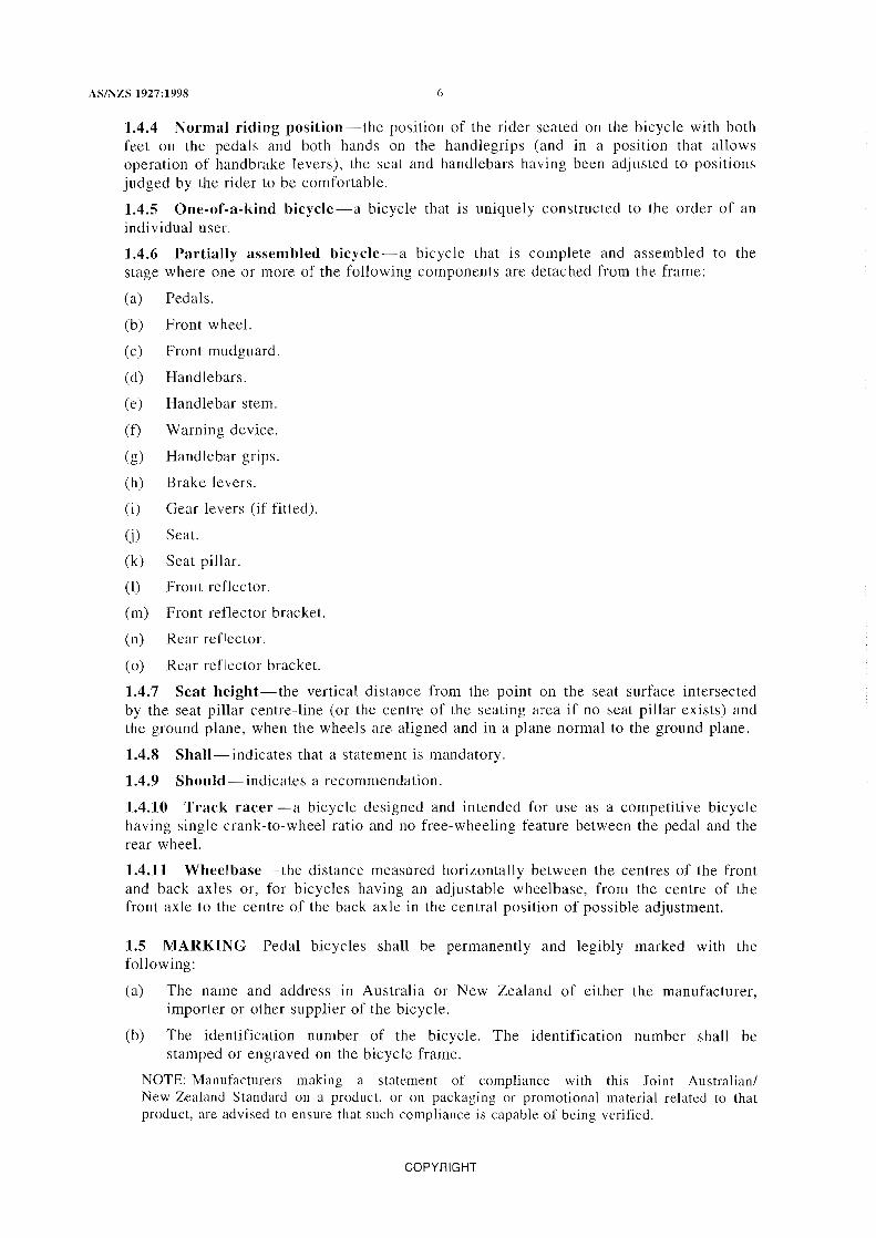
1.4.4 Normal riding position-the position of the rider seated on the bicycle with both feet on the pedals and both hands on the handlegrips (and in a position that allows operation of handbrake levers), the seat and handlebars having been adjusted to positions judged by the rider to be comfortable.
1.4.5 One-of-a-kind bicycle-a bicycle that is uniquely constructed to the order of an individual user.
] .4.6 Partially assembled bicycle-a bicycle that is complete and assembled to the stage where one or more of the following components are detached from the frame:
(a) Pedals.
(b) Front wheel.
(c) Front mudguard.
(d) Handlebars.
(e) Handlebar stem.
(0 Warning device.
(g) Handlebar grips.
(h) Brake levers.
(i) Gear levers (if fitted).
(j) Seat.
(k) Seat pillar.
(1) Front retlector.
(m) Front reflector bracket.
(n) Rear reflector.
(0) Rear reflector bracket.
1.4.7 Seat height-the vertical distance from the point on the seat surface intersected by the seat pillar centre-line (or the centre of the seating area if no seat pillar exists) and the ground plane, when the wheels are aligned and in a plane normal to the ground plane.
1.4.8 Sha1l- indicates that a statement is mandatory.
1.4.9 Should-indicates a recommendation.
1.4.10 Track racer-a bicycle designed and intended for use as a competitive bicycle having single crank-to-wheel ratio and no free-wheeling feature between the pedal and the rear wheeL
1.4.11 Wheelbase-the distance measured horizontally between the centres of the front and back axles or, for bicycles having an adjustable wheelbase, from the centre of the front axle to the centre of the back axle in the central position of possible adjustment.
1.5 MARKING Pedal bicycles shall be permanently and legibly marked with the following:
(a) The name and address in Australia or New Zealand of either the manufacturer, importer or other supplier of the bicycle.
(b) The identification number of the bicycle. The identification number shall be stamped or engraved on the bicycle frame.
NOTE: Manufacturers making a statement of compliance with this Joint Australian/ New Zealand Standard on a product, or on packaging or promotional material related to that product, are advised to ensure that such compliance is capable of being verified.
COPYRIGHT

7 AS/NZS 1927:1998
1.6 INFORMATIVE LABELLING
1.6.1 General Bicycles which require either adjustment or attachment and adjustment of components shall carry informative labelling complying with Clause 1.6.2. Clause 1.6.3, or Clause 1.6.4, as appropriate. In addition, bicycles styled to look like off-road bicycles but not designed for off-road use or stunting shall carry informative labelling complying with Clause 1.6.5.
1.6.2 Fully assembled bicycles with handlebars misaligned A warning statement sllch as the following shall be legibly and conspicuously printed on a label securely attached to the handlebars:
'Caution-before riding align the handlebars correctly with the forks, adjust the seat height, and tighten in accordance with the instructions in the manual.'
1.6.3 Partially assembled bicycles with handlebars misaligned and only pedals detached from the frame A warning statement sllch as the following shall be legibly and conspicuously printed on a label securely attached to the handlebars:
'Caution - before riding attach pedals and align the handlebars correctly with the forks, adjust the seat height, and tighten in accordance with the instructions in the manual.'
1.6.4 All other partially assembled bicycles The consumer package in which partially assembled bicycles, other than those described in Clause 1.6.3, are supplied shall have the following information legibly and conspicuously printed on the outside:
(a) In bold capital letters at least 15 mm in height:
'THIS IS A PARTIALLY ASSEMBLED BICYCLE REQUIRING THE ATTACHMENT OF THE FOLLOWING PARTS IN ACCORDANCE WITH THE MANUFACTURER'S INSTRUCTIONS.'
(b) In medium width capital letters at least 10 mm in height, a list of the components that are detached from the frame followed by a list of tools necessary to properly accomplish assembly and adjustment including a recommendation that a torque wrench be used.
In addition to the above, the following warning message shall be attached to each component of the partially assembled bicycle, or where some or all of the components are supplied in consumer packages, attached as a label to each package:
'WARNING: IN THE INTERESTS OF SAFETY IT IS RECOMMENDED THAT YOU HA VE THIS BICYCLE ASSEMBLED BY A SKILLED BICYCLE MECHANIC.'
The word 'warning' shall be in capitals at least 20 mm in height and the remainder of the message in letters at least 10 mm in height.
See also Clause 3.1 regarding assembly instructions to be provided with the bicycle.
1.6.5 Pseudo off-road or stunt bicycles Any bicycle which is styled or constructed in such a way that it may appear to be suitable for off-road or stunt use, but is not so suited (e.g. bicycles styled to look like 'BMX' or 'mountain' bicycles), shall have a warning statement such as the following, legibly and conspicuously printed on an adhesive label in bold capital letters not less than 3 mm high and securely attached to the bicycle in a prominent position:
'WARNING: THIS BICYCLE IS NOT DESIGNED FOR OFF-ROAD USE OR FOR STUNTING.'
1.7 INSTRUCTIONS FOR USE, MAINTENANCE AND ASSEMBLY An owner's manual containing instructions for use and maintenance based on the details given in Appendix A shall be attached to the bicycle or, for a partially assembled bicycle, placed within the consumer package. The owner's manual for the partially assembled bicycle shall also include simple, clear and adequate instructions for completion of the assembly, which shall meet the requirements specified in Clause 3.1.
COPYRIGHT

AS/NZS 1927:1998 8
Where the design of the front fork is sllch that the handlebars could be positioned and tightened with the fork in the reversed position, a diagram showing the correct assembly shall be included in the manual.
For maintenance and adjustments considered by the manufacturer to be beyond the capabilities of the consumer, guidance as to where such service can be obtained shall be supplied.
COPYRIGHT

9 AS/NZS ]927:1998
SECTION 2 DESIGN REQUIREMENTS FULLY ASSEMBLED BICYCLE
2.1 GENERAL Bicycles that are offered for supply in a partially assembled condition shall be assembled in accordance with the manufacturer's instructions in order to determine compliance with the requirements of this Section.
2.2 SHARP EDGES Bicycles shall have no unfinished sheared metal edges or other sharp parts that are exposed to hands or legs. Sheared metal edges that are not rolled shall be finished so that any sharp feathering of edges, or any sharp burrs or spurs caused by the shearing process, are removed.
This requirement is applicable to all parts of the bicycle that could come into contact with the hands and legs of the rider and to the following edges:
(a) At each end of the front mudguard.
(b) At the rear end of the rear mudguard.
(c) At each end of the chainguard.
(d) A t the end of the kickstand.
2.3 FASTENERS No fastener used to attach or secure components shall fracture, loosen, or otherwise fail its intended function during the tests required by this Standard. With the exception of bottom bracket cups, screw lengths shall be such that the threads of the internally threaded fastener are engaged by the screw either fully, or for a distance greater than one nominal screw diameter.
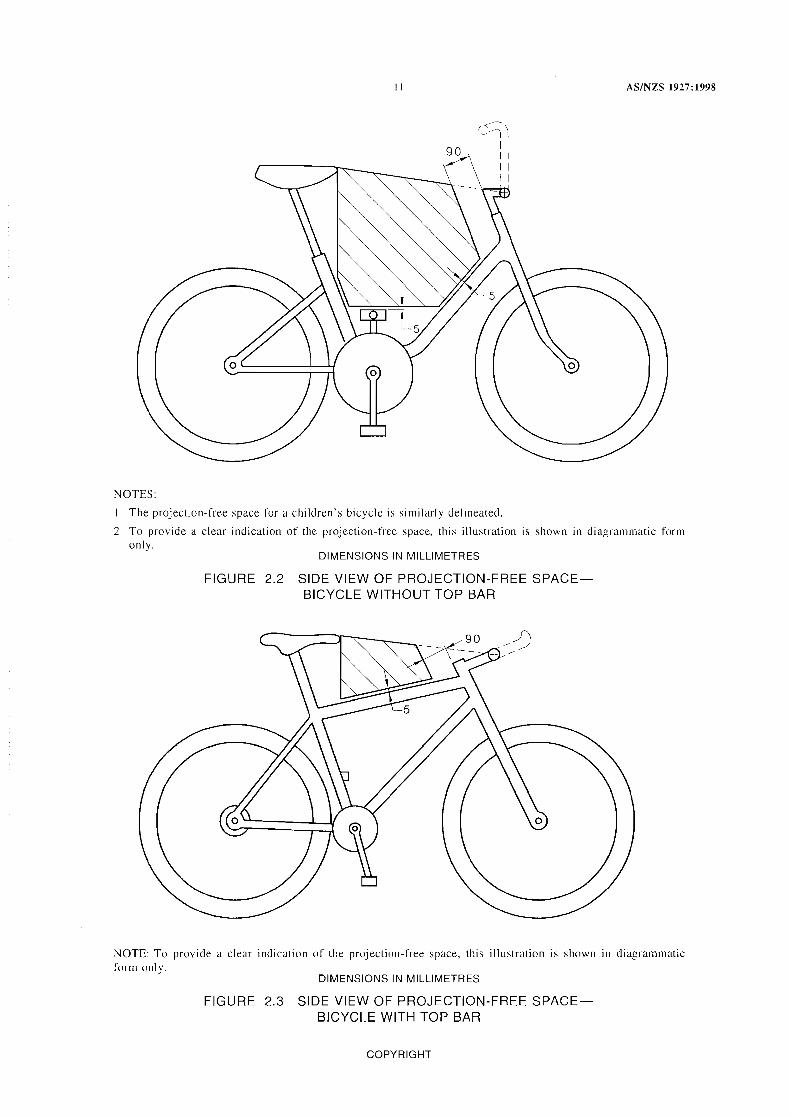
2.4 PROJECTIONS When the seat is adjusted to its highest and rearmost position, and the handlebars are adjusted to their highest position, there shall be no projections other than chain guard assemblies, control cables, and cable clamps or runners within the volume contained between parallel vertical planes 25 mm either side of a vertical plane through the frame of the bicycle and bounded by the sectional area described as follows (see Figures 2.1, 2.2 and 2.3):
(a) A line 90 mm to the rear of and parallel to the handlebar stem.
(b) A vertical line tangential to the forward tip of the seat.
(c) A line 5 mm above the top bar or a horizontal plane above the top surface of the uppermost pedal with the crank in a vertical position or surface connecting the head assembly and the seat assembly (and 5 mm to the front of and parallel to the seat bar, where applicable), except that control cables and cable clamps and mnners which are combined may protrude above the top bar a total of not more than 12 mm.
(d) A line connecting the front of the seat with the point of intersection of the handlebars and handlebar stem.
Bicycles, the configuration of which can be changed by the addition of a top bar, and bicycles with an extended seat or a mock petrol tank which is easily removable, shall comply with the above requirements in both configurations.
NOTE: While no projections are allowed in the above area, it is recommended that bicycles should be designed so that they have no projections which could cause injury.
COPYRIGHT

AS/NZS 1927:1998 10
2.5 CONTROL CABLES
2.5.1 Control cable ends The ends of the inner control cables shall be provided with end protectors to prevent unravelling. The protectors shall remain in position when subjected to removal forces in accordance with Appendix B.
2.5.2 Control cable abrasion Control cables shall be fitted in such a way as will ensure that the effects of abrasion are minimal.
NOTE: To provide a clear indication of the projection-free space, this illustration is shown in diagrammatic form only.
DIMENSIONS IN MILLIMETRES
FIGURE 2.1 TOP VIEW OF PRO~IECTION-FREE SPACE
COPYRIGHT
II AS/NZS 1927:1998
NOTES:
The projection-free space for a children's bicycle is similarly delineated.
2 To provide a clear indication of the projection-free space, this illustration is shown in diagrammatic form only.
DIMENSIONS IN MILLIMETRES
FIGURE 2.2 SIDE VIEW OF PROJECTION-FREE SPACEBICYCLE WITHOUT TOP BAR
NOTE: To provide a clear indication of the projection-free space, this ill ustration is shown in diagrammatic form only.
DIMENSIONS IN MILLIMETRES
FIGURE 2.3 SIDE VIEW OF PRO,IECTION-FREE SPACEBICYCLE WITH TOP BAR
COPYRIGHT

AS/NZS 1927:1998 12
2.6 GROUND CLEARANCE
2.6.1 Requirement When the bicycle is tested under the conditions specified in Clause 2.6.2, it shall be possible to tilt the bicycle sideways in the direction of the lower pedal as follows without the pedal or any other part, other than tyres, contacting the ground plane:
(a)
(b)
For a bicycle ................... not less than 25 degrees from the vertical.
For a children's bicycle ...... . not less than 20 degrees from the vertical.
2.6.2 Test conditions The bicycle shall be tested under the following conditions for compliance with Clause 2.6.1:
(a) With the tyres inflated to the pressure recommended by the manufacturer.
(b) With the pedal crank in a vertical position with the lower pedal horizontal fore and aft.
(c) With toe clips, where fitted, uppermost.
(d) With any training wheels removed.
This test shall be applied with each pedal separately in the lower position.
For a bicycle equipped with a sprung suspension, the measurement shall be taken with the suspension in a depressed position such as would be caused by a rider weighing-
(i) for other than children's bicycles ............................. 70 kg; or
(Ii) for children's bicycles ....................................... 23 kg.
2.7 TOE CLEARANCE Bicycles not equipped with foot retaining devices, such as toe clips, shall have at least 88 mm clearance between the pedal and the front tyre or mudguard when the wheel is turned to any position. The clearance shall be measured forward and parallel to the longitudinal axis of the bicycle from the centre of either pedal to the arc swept by the tyre or mudguard. (See Figure 2.4.)
Min. toe clearance
Mudguard Bicycle pedal
FIGURE 2.4 TOE CLEARANCE
COPYRIGHT

13 AS/NZS 1927:1998
2.8 WHEELS
2.8.1 Hub-to-frame attachment The attachment of wheel hubs to the bicycle frame shall be in accordance with the following:
(a) Locking devices-General Both front and rear wheels shall be secured to the bicycle frame with a positive locking device. Locking nuts on threaded axles shall be tightened to the manufacturer's specifications. The minimum removal torque shall be 80% of the manufacturer's recommended tightening torque.
(b) Wheel retention-General There shall be no relative movement between the axle and the frame (rear wheel) or front fork (front wheel) when a force of 2300 ±20 N is applied symmetrically to the axle in the direction of wheel removal for a period of 30 s.
(c) Quick-release devices Any quick -release device shall have the following common operating features:
(i) The quick-release mechanism shall be adjustable to allow setting for tightness.
Oi) lts form and marking shall clearly indicate whether the mechanism is in the open or locked position.
(iii) If adjustable by a lever, the force required to close a properly set lever shall not exceed 200 N.
(iv) The releasing force of the clamping mechanism when closed shall not be less than 50 N.
(v) If operated by a lever, the quick-release mechanism shall withstand without fracture or permanent deformation a closing force of not less than 300 N applied with the adjustment set to prevent full closure under this force.
(vi) The wheel retention with the quick-release mechanism in the clamped position shall be in accordance with Item (b).
If applied to a lever, the forces in Items (iii), (iv) and (v) shall be applied 5 mm from the tip end of the lever.
(d) Positive retention-Front hubs The front hub to frame connection shall incorporate a positive retention feature such that, when subjected to the retention test at Appendix C, the hub will not separate from the bicycle frame. Where a hub equipped with a quick-release device is to be used, the positive retention feature shall be an integral part of the fork ends and shall not rely upon any removable fitting such as a washer or key plate to achieve the requirement.
2.8.2 Clearance The wheel assembly shall be aligned so that the clearances between the rim and the frame and the tyre and the frame are respectively not less than S mm and not less than 3 mm when the wheel is rotated to any position.
2.8.3 Tyres Inflatable tyres shall have the inflation pressure recommended by the tyre manufacturer moulded into or onto the side wall of the tyre in letters not less than 3 mm in height. Where the recommended pressure is stated in units other than kilopascals, the equivalent pressure in kilopascals shall be shown in the instruction manual.
NOTE: Compliance with this requirement may be achieved by the inclusion in the instruction manual of a conversion table which gives the kilopascal equivalents for the various recommended tyre pressures stated in imperial units on the side walls of bicycle tyres.
COPYRIGHT

AS/NZS 1927:1998 14
2.9 PROTECTIVE GUARDS
2.9.1 Chainguards Bicycles shall be equipped with a chainguard shielding the upper junction of the chain and chainwheel (drive sprocket) to prevent entrapment of clothing or body parts. The chainguard shall be as follows:
(a) Children's bicycles A guard enclosing the chainwheel and upper run of the chain (e.g. the 'hockey stick' guard).
(b) Other than children's bicycles A guard shielding the upper junction of the chain and chain wheel (drive sprocket) against the entrapment of clothing or body parts. It shall be either-
(i) a fixed guard or a front derailleur chain guide that shields the chain for a distance of at least 25 mm measured prior to the first point of engagement of the chain with the chainwheel (see Figure 2.5); or
Cii) a disc of impact resistant material attached to the chainwheel with a diameter not less than 10 mm larger than the diameter of the chain wheel measured over the tips of the teeth (see Figure 2.6).
The chainguard brackets shall be sufficiently strong to ensure that the chainguard is held in a finn and stable position. Chainguards shall not be removable other than by use of a tool.
2.9.2 Spoke protection The rear wheel of bicycles fitted with derailleur gears shall be guarded to prevent the drive chain or derailleur from interfering with or stopping the rotation of the wheel through improper adjustment of the rear derailleur.
2.10 DRIVE CHAIN The drive chain shall operate over the sprockets without catching or binding. Where a chain is joined by a connecting link, the chain shall be correctly assembled on the bicycle, e.g. if an open-end spring clip is used the chain shall be mounted to operate over the sprockets with the open end trailing.
;}25 mm ,-' 00-. -~-~--l-t-- Chain is to be guarded
in the shaded zone
/
\
FIGURE 2.5 CHAIN AND CHAINWHEEL JUNCTION
COPYRIGHT

15 AS/NZS 1927:1998
Ring
FIGURE 2.6 CHAINWHEEL DISC
2.11 PEDALS
2.11.1 Construction Pedals shall have right-handlleft-hand symmetry and the tread shall be an integral part of the pedal constmction to the extent that removal of the tread material would substantially destroy the pedal. The tread shall be present on both top and bottom surfaces of the pedal, except that, if the pedal has a definite preferred position, the tread surface need only be on the surface intended for the rider's foot.
2.11.2 Toe clips Pedals intended for use only with toe clips shall have toe clips securely attached to them and need not have tread surfaces. Pedals designed for optional use of toe clips shall have tread surfaces.
2.11.3 Sole clips Sale clip systems comprising a fitting on each pedal and a mating fitting on the rider's shoe sale, shall be designed and fitted so that the mating parts connect positively and securely with a simple action of the foot, and are readily released.
2.12 STEERING SYSTEM
2.12.1 Handlebar The handlebars shall allow comfort to the rider and safe control of the bicycle. The maximum overall width of the handlebars and rigid attachments shall be not greater than 700 mm. Any fittings extending beyond this width shall be frangible. Handlebar ends shall be symmetrically located with respect to the longitudinal axis of the bicycle and not more than 400 mm above the seat surface when the seat is in its lowest position and the handlebar ends are in their highest position.
2.12.2 Handlebar ends The ends of the handlebars shall be capped or otherwise covered using handgrips, end plugs, control shifters, or other end-mounted devices. They shall remain in position when subjected to removal forces in accordance with Appendix B.
2.12.3 Handlebar stem insertion mark Either the handlebar stem shall contain a permanent ring or mark which clearly indicates the minimum insertion depth of the
COPYRIGHT

AS/NZS 1927:1998 16
handlebar stem into the fork assembly, or a positive and permanent means of ensuring the minimum insertion depth shall be provided. The insertion mark shall be not less than 2.5 times the stem diameter from the lowest point of the stem, and shall not affect the structural integrity of the stem, the strength of which shall be maintained for not less than a distance of one stem diameter below the mark.
2.12.4 Handlebar stem to fork connection The dimensional tolerance of the outside diameter of the handlebar stem with respect to the inside diameter of the fork tube shall be from a minimum of a sliding fit to a maximum clearance of 1.0 mm.
2.13 SEA T PILLAR The seat pillar shall contain a permanent mark or ring located not less than two pillar shaft diameters from the lowest point on the pillar shaft. The mark shall not affect the structural integrity of the seat pillar, the strength of which shall be maintained for a distance of not less than one pillar shaft diameter below the mark. A test of the strength of the seat pillar shall be conducted in conjunction with the seat adjustment clamp test specified in Clause 3.3.
The seat pillar and saddle assembly shall incorporate a substantial positive means of preventing the pillar or other supporting structure from penetrating the saddle.
NOTE: Typical means of preventing penetration of the saddle include mechanical obstructions such as shoulders, end stops, clamps, and the like.
2.14 BRAKING SYSTEM
2.14.1 General All bicycles shall be equipped with not less than two brakes, one acting on the front wheel and one on the rear wheel. On a children's bicycle one brake shall be a back-pedal brake.
Brakes shall comply with the relevant requirements of Clauses 2.14.2, 2.14.3, and 2.14.4.
The braking system shall operate without binding and shall comply with the relevant performance requirements of Clause
2.14.2 Handbrakes
NOTE: This Clause makes no distinction between handbrake levers and auxiliary hand brake levers, each kind of lever is required to meet all of the requirements.
2.14.2.1 Handbrake lever location The brake lever for a front brake shall be positioned on the right-hand side of the handlebar, and that for a rear brake on the left-hand side.
2.14.2.2 Handbrake lever attachment Handbrake lever mechanisms shall be attached to the handlebars in a position that is readily accessible to a rider in the normal riding position.
The means of fixing the handbrake levers to the handlebars shall withstand vibration, shall incorporate locking devices such as matching recesses, lock washers, locknuts, tab washers or split pins, and shall not loosen when the hand lever is tested in accordance with Paragraph D4, Appendix D.
2.14.2.3 Handbrake grip dimensions The dimensions of handbrake grips shall be as follows:
(a) Bicycles with a wheelbase greater than 765 mm The maximum overall dimension between the handbrake lever and the handlebar measured in a plane perpendicular to the centre-line of the handlebar shall not exceed 90 mm at any point between the cable end of the lever and the lever midpoint. The grip dimension may increase towards the open end of the lever, but shall not increase by more than 12 mm except for the last 12 mm of the lever. The length of roller lever brakes shall be measured from the bend in the handbrake lever. (See Figures 2.7 and 2.8.)
COPYRIGHT

17 AS/NZS 1927:1998
(b) Bicycles with dropped handlebars The maximum grip dimension of the contoured handbrake lever intended for finger engagement shall not exceed 90 mm.
(c) Children's bicycles The maximum grip dimension as defined in Item (a) above shall not exceed 60 mm.
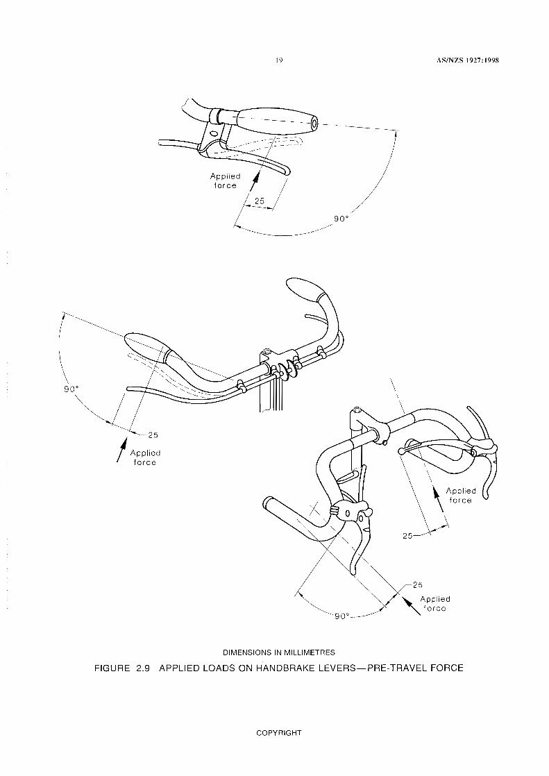
2.14.2.4 Pre-travel force When applied to the handbrake lever at a point 25 ±l mm from the open end of the hand lever and in a direction normal to the handlebar grip in the plane of travel of the lever, as shown in Figure 2.9, the force required to cause the brake pads to contact the braking surface of the wheel shall not exceed 45 N.
Lever mid pointJ
T Maximum
grip dimension
/ -- t '-.-.
Llncrease toward end of lever. 12 max.
DIMENSIONS IN MILLIMETRES
FIGURE 2.7 TYPICAL HANDBRAKE LEVER SHOWING GRIP DIMENSIONSTRAIGHT HANDLEBARS
2.14.2.5 Brake pad assembly The brake friction pad shall be securely attached to the backing plate or holder, and the friction pad assembly shall not fail when tested in accordance with Paragraph D4, Appendix D.
2.14.2.6 Brake adjustment When the rim calliper brakes are correctly adjusted and applied, the brake pads shall not contact anything other than the wheel rim. The brakes shall be capable of adjustment to an efficient operating position until the brake pads have worn to the point of requiring replacement as recommended in the owner's manual (see Clause 1.7).
2.14.2.7 Attachment of brake assemblies Brake assemblies shall be securely attached to the frame or fork or handlebar by means of a fixing device which can withstand vibration or be held with locking devices such as matching recesses, lock washers, locknuts, tab washers or split pins, and shall not loosen when the handbrake is tested in accordance with Paragraph D4, Appendix D. The cable anchor bolt shall not cut any of the cable strands.
2.14.2.8 Camilever brakes Where cantilever brakes are fitted, a safety device shall be fitted to prevent the stirrup cable from contacting the tyre in the event of failure of the main brake cable.
COPYRIGHT

AS/NZS J927:J998 18
~
L 2
Direction of inboard orthographic view below
RIGHT HANDLEBAR
Calliper brake cable
lever
" Maximum " grip dimension
V
Maximum grip dimension
FIGURE 2.8 TYPICAL HANDBRAKE LEVER SHOWING GRIP DIMENSIONDROPPED HANDLEBAR
2.14.3 Back-pedal brakes
2.14.3.1 Operating force Back-pedal brakes shall be actuated by a force applied to the pedal in a direction opposite to that of the drive force.
2.14.3.2 Crank differential The differential between the drive and brake positions of the crank shall be not more than 60 degrees when the crank is placed alternately against each position under a torque of not less than 15 N.m.
2.14.3.3 Independent operation The brake mechanism shall function independently of any drive-gear position or adjustment.
2.14.4 Handbrakes and back-pedal brakes in combination Bicycles equipped with back-pedal brakes and handbrakes shall comply with all the requirements specified in Clauses 2.14.2 and 2.14.3.
COPYRIGHT
Applied force
19
DIMENSIONS IN MILLIMETRES
\
AS/NZS 1927:1998
\ \ \ \
\\ \APPlied force
2SY
FIGURE 2.9 APPLIED LOADS ON HANDBRAKE LEVERS-PRE-TRAVEL FORCE
COPYRIGHT

AS/NZS 1927:1998 20
2.15 REFLECTORS
2.15.1 New Zealand only Reflectors shall be fitted to the bicycle and shall comply with the requirements of the New Zealand Traffic Regulations 1976. NZS 5441, Parts I and 2 provide technical guidance on the requirements of these Regulations.
2.15.2 Australia only
2.15.2.1 General Bicycles shall be fitted with front, rear, side, and pedal reflectors complying with AS 2142.
Reflectors and their mounts to the bicycle shall incorporate a distinct and preferred assembly method where this is necessary to ensure their correct alignment and rotation.
2.15.2.2 Rear reflectors At least one red rear reflector shall be fitted as follows:
(a) The mounting position shall be above the level of the back axle, and shall be such that the reflector(s) are not obscured from view, e.g. by the rider's clothing or by the wheel.
(b) The optical axis of the reflector(s) shall be directed rearwards within 5 degrees of the horizontal/vertical alignment of the bicycle when the wheels are tracking in a straight line, and shall have a clear field of view of 50 degrees.
(c) The rotation of the reflector(s) about the optical axis shall be within 5 degrees of the design orientation.
2.15.2.3 Side reflectors Each wheel shall be fitted with at least one yellow side reflector as follows:
(a) The reflector or reflectors shall be visible from both sides of the bicycle.
(b) The centre of the reflector or reflectors shall be within 76 mm of the inside of the wheel rim.
(c) The reflector or reflectors shall be mounted either flat on the spokes or within the spoke cage so that the angle between the optical axis and the normal to the plane of the wheel does not exceed the angle between the spokes and the plane of the wheel.
2.15.2.4 Pedal reflectors Yellow pedal reflectors shall be mounted on the front and rear sides of all pedals.
2.15.2.5 Front reflector At least one white reflector at least shall be fitted as follows:
(a) The mounting position shall be above the level of the front axle and below the level of the handlebars and such that the reflector(s) are not obscured from view, e.g. by a basket.
(b) The optical axis of the retlector(s) shall be directed forwards within 5 degrees of the horizontal/vertical alignment of the bicycle when the wheels are tracking in a straight line, and shall have a clear field of view of 50 degrees.
(c) The rotation of the reflector(s) about the optical axis shall be within 5 degrees of the design orientation.
2.16 WARNING DEVICE-AUSTRALIA ONLY An efficient bell or some other suitable audible warning device shall be fitted.
NOTE: There is no regulatory requirement in New Zealand for a warning device to be fitted to a bicycle.
2.17 LIGHTING EQUIPMENT
2.17.1 New Zealand only Lighting equipment shall comply with New Zealand Traffic Regulations 1976. NZS 5441 Parts I and 2 provide technical guidance on the requirements of these Regulations.
2.17.2 Australia only Where lights are fitted to a bicycle, lighting equipment as specified in AS 3562, or as otherwise permitted by the regulatory authority, shall be fitted.
COPYRIGHT

21
SECTION 3 PERFORMANCE FULLY ASSEMBLED
AS/NZS 1927:1998
REQUIREMENTS BICYCLE
3.1 ASSEMBLY INSTRUCTIONS Bicycles that are offered for supply in a partially assembled condition shall have included in the owner's manual in the consumer package, simple, clear and adequate instmctions for the completion of the assembly. Prior to determining compliance with the remainder of the requirements of this Section, the tester shall assemble the test bicycle strictly and only in accordance with those instructions. Failure to meet any requirements of this Section due to inadequacies in the instructions shall constitute failure to meet the requirements of this Clause.
3.2 ROAD WORTHINESS When a bicycle other than a children's bicycle is tested in accordance with Appendix E, it shall exhibit stable handling, turning, and steering characteristics without difficulty of operation, and either during or at the completion of the test there shall be no failure of any part of the bicycle nor shall there be any loosening or misalignment of the seat, handlebars, controls or reflectors, or loss of any components or accessories from the bicycle.
3.3 SEAT PILLAR AND SEAT ADJUSTMENT CLAMP STRENGTH The seat adjustment clamps shall be capable of securing the seat in any position to which it can be adjusted.
When the seat pillar and seat adjustment clamps are tested in accordance with Appendix F, there shall be no fracture or permanent deformation of the seat pillar, or permanent movement greater than 10 mm at the point of application of the force.
3.4 STEERING STABILITY The steering shall be free to turn through at least 60 degrees either side of the straight-ahead position and shall exhibit no tight spots, stiffness or slackness in the bearings when correctly adjusted.
A minimum of 25 percent of the total mass of the bicycle and rider shall act on the front wheel when the rider is holding the handlebar grips and sitting on the saddle, with the saddle and rider in their most rearward positions, and the bicycle on level ground.
NOTE: Recommendations for steering geometry are given in Appendix G.
3.5 BRAKING
3.5.1 Handbrake performance requirements Before handbrakes are tested for compliance with the braking performance requirements specified in Clause 3.5.3, they shall comply with the following requirements:
(a) Handbrake strength-loading method When the handbrake system is tested in accordance with Paragraph D3, Appendix D, no visible fractures, failures, permanent deformation or misalignments shall result.
(b) Hamlbrake strength-rocking method When the handbrake system is tested in accordance with Paragraph D4, Appendix D, no loosening or permanent deformation of brake pads, pad holders, cable and hand lever securing devices of any other functional brake component shall result.
3.5.2 Back-pedal brake performance requirements Before a back-pedal brake is tested for compliance with the braking performance requirements specified in Clause 3.5.3 (in combination with a handbrake), it shall comply with the following requirements:
(a) Brake force linearity for other than children's bicycles When determined in accordance with Paragraph D5, Appendix D the brake force shall be linearly proportional (within 20 percent) for pedal forces of 90 N to 300 N, and shall be not less than 180 N for a pedal force of 300 N.
COPYRIGHT

AS/NZS 1927:1998
(b) Brake force linearity for children '.I bicycles When the back-pedal brake on a children's bicycle is tested in accordance with Paragraph OS, Appendix 0, the brake force shall be linearly proportional (within 20 percent) for pedal forces from 45 N to 225 N, and the ratio of applied pedal force to braking force transmitted to the rear wheel shall not exceed 2 to 1 at any time.
(c) System strength lest When the back-pedal brake is tested in accordance with Paragraph 06, Appendix 0, there shall be no failure of the brake system or any part thereof.
3.5.3 Braking performance When the braking system is tested in accordance with Appendix H, the calculated stopping distance shall not exceed 5.5 m.
COPYRIGHT

23 AS/NZS 1927:1998
SECTION 4 PERFORMANCE REQUIREMENTS -SUBASSEMBLIES
4.1 GENERAL Subassemblies which have been tested to determine compliance with the requirements of this Section shall not be used in the manufacture of bicycles intended for sale or supply.
4.2 STATIC LOAD ON WHEEL When tested in accordance with Appendix T, there shall be no failure of any component of the wheel and the maximum permanent deformation of the rim, measured at the point of application of the force, shall not exceed 1.5 mm.
4.3 FRONT FORK When tested in accordance with Appendix J, the front fork shall absorb an energy of not less than 40 J without visible evidence of fracture.
4.4 FORK AND FRAME ASSEMBLY When tested in accordance with Appendix K, the fork and frame assembly shall not show any evidence of fracture or permanent frame deformation.
4.5 HANDLEBAR ASSEMBLY
4.5.1 Handlebar stem When tested in accordance with Paragraphs L2 and L3, Appendix L, the handlebar stem shall not show visible fractures.
4.5.2 Handlebars and clamps The handlebar and clamps shall comply with the following requirements:
(a) Stem-to-fork clamps When the handlebars are tested in accordance with Paragraph L4, Appendix L, the stem-to-fork clamps shall prevent movement of the stem.
(b) Handlebars and stem assembly strength When tested in accordance with Paragraph LS, Appendix L, the handlebars and stem assembly shall comply with the following requirements:
(i) There shall be no movement of the handlebars relative to the stem.
(ii) There shall be no visible fracture of the handlebars or stem assembly.
(iii) Residual deflection of handlebars shall not exceed 5 mm except that, for those handlebars having a radius greater than 350 mm measured from the axis of their attachment point to the handlebar stem to the centre of the handgrip, the residual deflection shall not exceed 25 mm.
4.6 BRAKE FRICTION PADS-HEAT RESISTANCE When placed in a pre-heated oven at a temperature of 120 ±3°C for 30 min, the brake pad material shall not melt or blister.
4.7 DRIVE CHAIN The drive chain, including the connecting link or join, for all bicycles shall withstand without failure a tensile force of 8 kN.
4.8 PEDAL When tested in accordance with Appendix M, the shaft of the pedal shall not break away from the crank.
COPYRIGHT
AS/NZS 1927:1998 24
APPENDIX A
OWNER'S MANUAL
(Normative)
The owner's manual shall include information on the following:
(a) Assembly instructions Assembly instructions and a list of tools necessary to accomplish proper assembly and adjustment of the particular model, including a recommendation that the torque requirements listed in the maintenance section of the manual be also observed during initial assembly and that a torque wrench be used.
Adequate instructions including diagrams where the design of the fork is such that there is a possibility that the handlebars could be aligned with the forks in the reversed position.
(b) Preparation for riding The following shall be included:
(i) Instructions on how to measure and adjust the bicycle to suit the size of the rider.
(ii) Instructions on adjustment of seat height and handlebar height with an explanation of the insertion warning marks on the seat post and handlebar stem.
(iii) Recommended tyre pressure, in kilopascals.
(c) Use The following shall be included:
(i) Safe operation on the road, including instructions on the operation of the brakes and gears.
(ii) Warning concerning increased braki ng distance in wet weather.
(d) Maintenance The following shall be included:
(i) Recommended lubricants and where and how often to lubricate.
(ii) Correct chain tension and the method of adjustment, including an instruction, where appropriate, to mount the chain with the open end of the spring clip trailing.
(iii) Method of adjusting the brakes, including adjustment, operation, and use of brake quick-release devices, where fitted.
(iv) Adjustment, operation, and use of hub quick-release devices, where fitted.
(v) Adjustment, operation, and use of seat pillar quick-release devices, where fitted.
(vi) Instructions on replacement of brake blocks.
(vii) Recommended torque requirements in newton metres for the following:
(A) Front axle nuts.
(B) Back axle nuts.
(C) Handlebar clamp nut/bolt.
(D) Handlebar stem expander bolt.
(E) Seat pillar clamp nut/bolt.
(F) Brake cable anchor bolt.
COPYRIGHT

(G) Brake centre bolt.
(H) Seat clamp nuts.
(I) Cotter pin nuts.
25
(viii) Recommendation that a torque wrench be used.
AS/NZS 1927:1998
(ix) A warning that handlebar hand grips or tube end plugs should be replaced if damaged, as bare tube ends have been known to cause injury. The warning shall state that it is particularly important that bicycles used by children be checked regularly to ensure that adequate protection for the ends of the handlebars are in place.
(e) Repair A warning that replacement forks must have the same rake and same tube inner diameter as those originally fitted to the bicycle.
COPYRIGHT
AS/NZS 1927:1998 26
APPENDIX B
TEST OF PROTECTIVE CAPS AND END-MOUNTED DEVICES
(Normative)
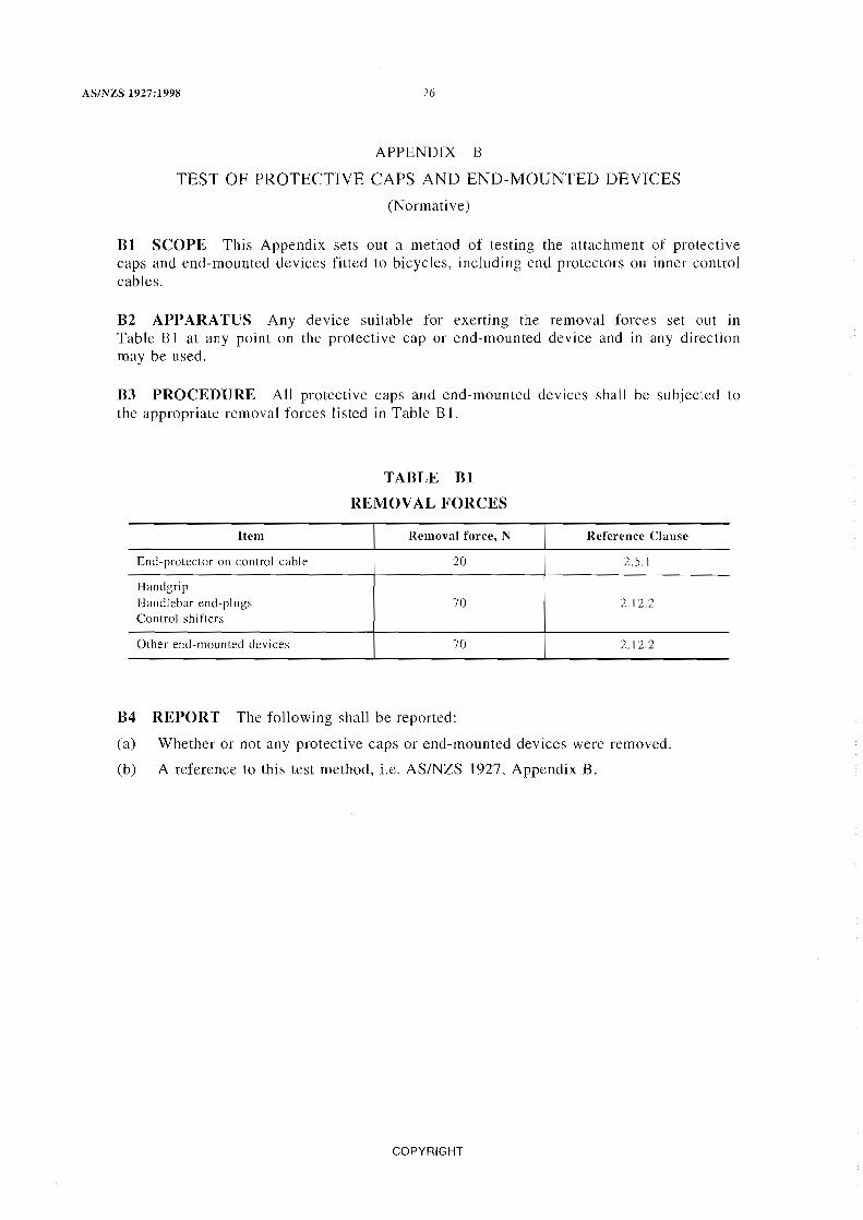
Bl SCOPE This Appendix sets out a method of testing the attachment of protective caps and end-mounted devices fitted to bicycles, including end protectors on inner control cables.
B2 APPARATUS Any device suitable for exerting the removal forces set Ollt in Table Blat any point on the protective cap or end-mounted device and in any direction may be used.
B3 PROCEDURE All protective caps and end-mounted devices shall be subjected to the appropriate removal forces listed in Table B] .
Item
End-protector on control cable
Handgrip Handlebar end-plugs Control shifters
Other end-mounted devices
TABLE Bl
REMOVAL FORCES
Removal force, N
20
70
70
B4 REPORT The following shall be reported:
Reference Clause
2.5.1
2.12.2
2.12.2
(a) Whether or not any protective caps or end-mounted devices were removed.
(b) A reference to this test method, i.e. AS/NZS 1927, Appendix B.
COPYRIGHT
27 AS/NZS 1927:1998
APPENDIX C
FRONT HUB RETENTION TEST
(Normative)
Cl SCOPE This Appendix sets out the method for determining the adequacy of front hub positive retention features.
C2 PRINCIPLE The test involves the loosening of front hub locking devices by a specified amount and determining whether the front hub can be pulled away from the forks when a specified load is applied.
C3 APPARATUS The following apparatus is required:
(a) A means of clamping the frame of the bicycle.
(b) A device capable of applying a load of 30 N to the hub in the direction of the open ends of the slots in the forks.
C4 PROCEDURE The procedure shall be as follows:
(a) Open or, if necessary, remove front brake calipers so that they will not retard any potential pulling away of the wheel from the front fork.
(b) With the bicycle frame suitably clamped loosen the front hub locking devices as follows:
(i) Nuts on threaded axle Loosen each nut and retighten until it is finger tight and loosen again a further one complete turn.
(ii) Lever operated quick-release device Adjust the locking lever so that when engaged, a force of 50 ±5 N, applied at a point 5 mm from the tip end of the lever, is required to release it. Release the lever and undo the adjusting nut two full turns.
(iii) Other locking device Adjust the device so that it is finger tight only and release it one notch or one full turn as appropriate.
(c) Apply a force of 30 ±5 N to the front wheel or hub parallel to the slots in the forks and in the direction of the open ends.
(d) Note whether the hub pulls away from the forks.
CS REPORT The following shall be reported:
(a) The type of locking device tested.
(b) Whether the hub pulled away from the frame.
(c) A reference to this test method, i.e. AS/NZS 1927, Appendix C.
COPYRIGHT
AS/NZS 1927:1998 28
APPENDIX D
HANDBRAKE AND BACK-PEDAL BRAKE STRENGTH TESTS
(Normative)
Dl SCOPE This Appendix sets out methods of determining both the strength of hand and back-pedal braking systems of bicycles and the linearity of the back-pedal brake.
D2 TEST CONDITIONS These tests shall be carried out on a bicycle fully assembled in accordance with the manufacturer's instructions.
The bicycle is required to undergo the performance test specified in Appendix H immediately after these tests have been carried out and without making any further adjustments to the brakes.
Bicycles equipped with auxiliary handbrake levers shall be tested with those levers in place, and the auxiliary handbrake levers shall be considered to be handbrake levers.
Examinations for fractures in components shall be carried out at x5 magnification.
D3 HANDBRAKE STRENGTH TEST -LOADING METHOD
D3.1 Apparatus A spring scale or other suitable device for measuring the specified forces is required.
D3.2 Procedure
D3.2.1 Handbrake lever The procedure for handbrake levers shall be as follows:
(a) Adjust the braking mechanism for minimum working clearance between the brake pads and the braking surface with the brake fully released.
(b) Actuate the handbrake levers by applying a force at a point not more than 25 mm from the open end of the lever and in a direction normal to the handlebar grip in the plane of travel of the lever (see Figure 2.9) until-
(i) a force of 450 N is reached;
(ii) the handbrake lever is in the same plane as the upper surface of the handlebars; or
(iii) the handbrake lever contacts the handlebars.
(c) Apply the loading as specified in Step (b) a total of 10 times.
(d) Examine all brake components and record any visible fractures, failures, permanent deformation, or misalignments.
D3.2.2 Auxiliary handbrake lever The procedure for auxiliary hand brake levers shall be as follows:
(a) Adjust the braking mechanism for minimum working clearance between the brake pads and the braking surface with the brake fully released.
(b) Actuate the auxiliary handbrake lever by applying a force at a point not more than 25 mm from the open end of the lever and in a direction normal to the lever grip in the plane of travel of the lever (see Figure 2.9) until-
(i) a force of 450 N is reached;
(ii) the auxiliary hand brake lever is in the same plane as the upper surface of the handlebars; or
(iii) the auxiliary handbrake lever contacts the handlebars.
COPYRIGHT

29 AS/NZS 1927:1998
(c) Apply the loading as specified in Step (b) a total of 10 times.
(d) Examine all brake components and record any visible fractures, failures, permanent deformation or misalignments.
D3.3 Report The following shall be reported:
(a) Whether or not there was any visible evidence of fractures, failures, permanent deformation, or misalignment of any part or component of the handbrake system.
(b) A reference to this test method, i.e. AS/NZS 1927, Appendix 0, Paragraph 03.
D4 HANDBRAKE STRENGTH TEST-ROCKING METHOD
D4.1 Apparatus The following apparatus is required:
(a) A spring scale or other suitable device for measuring the specified forces.
(b) A mass of 70 ±2 kg.
(c) A dry, clean, level, paved surface of adequate length.
D4.2 Procedure The procedure shall be as follows:
(a) Load the seat surface with the mass.
(b) Actuate each braking system as in Paragraph 03.2.
(c) Rock the bicycle forward and backward over the paved surface at least six times and for a distance of at least 80 mm in each direction.
D4.3 Report The following shall be reported:
(a) Whether or not there was any loosening or permanent deformation of brake pads, pad holders, or cable and hand lever securing devices, or of any other functional brake component.
(b) A reference to this test method, i.e. AS/NZS 1927, Appendix 0, Paragraph 04.
DS BACK·PEDAL LINEARITY TEST
DS.l Apparatus The following apparatus is required:
(a) Suitable length of webbing tape approximately 20 mm wide.
(b) A spring scale or other suitable device for measuring the braking force.
(c) A means of applying a minimum of five different forces to the pedal between 45 N and 225 N for children's bicycles and between 90 Nand 300 N for other than children's bicycles. Two of the test forces shall be the minimum and maximum force specified for each bicycle type.
NOTE: Other apparatus may be used provided that it operates as efficiently.
DS.2 Procedure
DS.2.1 Bicycles other than children's bicycles The procedure shall be as follows:
(a) Apply the lowest force of 90 N to the pedal at right angles to the crank and in the direction of braking.
(b) Wind the tape around the circumference of the tyre.
(c) Apply a steady pull and after a minimum of one revolution of the wheel measure the braking force tangential to the circumference of the tyre on the spring scale.
(d) Record the reading.
(e) Repeat Steps (c) and (d) twice more.
COPYRIGHT

AS/NZS 1927:1998 30
(f) Plot the average of the three readings at this load level onto a graph of pedal force versus braking force.
(g) Repeat Steps (a) to (f) at a minimum of four additional pedal force loadings up to and including 300 N.
(h) The following procedure shall apply:
(i) If the average of the three readings at the 300 N load level is below 180 N, proceed no further with the test.
(ii) If the average of the three readings at the 300 N load level is above 180 N, prepare a graph showing the 'best fit' line and the 20 percent limit lines obtained by the 'least squares' method outlined in Appendix N.
DS.2.2 Children's bicycles For children's bicycles, the procedure in Paragraph DS.2.1, Steps (a) to (g) shall apply, except that the lowest force in Step (a) shall be 4S N and the highest pedal force loading in Step (g) shall be 22S N.
The following procedure shall also apply:
(a) If the ratio of pedal force to braking force exceeds 2 to 1 at any pedal force, proceed no further with the test.
(b) If the ratio of pedal force to braking force does not exceed 2 to 1, prepare a graph showing the 'best fit' line and the 20 percent limit lines obtained by the 'least squares' method outlined in Appendix N.
DS.3 Report The following shall be reported:
(a) The pedal forces used, the braking force achieved for each pedal force used and, for children's bicycles only, the ratio of pedal force to braking force. The graph referred to in Paragraph DS.2.1(h)(ii), or Paragraph DS.2.2 shall be appended to the report.
(b) A reference to this test method, i.e. AS/NZS 1927, Appendix D, Paragraph DS.
D6 BACK-PEDAL BRAKE SYSTEM STRENGTH TEST
D6.1 Apparatus A spring scale or other suitable device for measuring the specified force is required.
D6.2 Procedure The procedure shall be as follows:
(a) Place the pedal cranks in a horizontal position as shown in Figure Dl.
(b) Apply a force of IS00 N gradually in a vertical direction to the centre of the left-hand pedal axle, as shown in Figure D l.
(c) Fully maintain this force for IS s.
(d) Repeat the above procedure a total of lO times.
D6.3 Report The following shall be reported:
(a) Whether or not there was any failure of the brake system or component thereof.
(b) A reference to this test method, i.e. AS/NZS 1927, Appendix D, Paragraph D6.
COPYRIGHT

/"T""'>.
I
I
I I
I
I I
I I
~rr~ I
rti LH cran1k J
I I
31 AS/NZS 1927:1998
(POiot 0 force a
I
pplication
/ I I
J! I
Y
LLH crank
chainwheel and pedal crank
"
'- Pedal
Hub sprocket,
C"iO~= \
FIGURE D1 BACK-PEDAL BRAKE SYSTEM STRENGTH TEST
COPYRIGHT

AS/NZS 1927: 1998 32
APPENDIX E
ROAD TEST
(Normative)
E1 SCOPE This Appendix sets out a method of determining the stability and handling characteristics, and the strength and durability of a bicycle by riding it over a cleated test course.
E2 TEST COURSE The test course shall comprise a straight cleated course not less than 30 m long on a horizontal hard paved test surface. The cleats shall be made of wood and shall be 25 ±2 mm high by 50 ±5 mm wide with a 12 ±2 mm by 12 ±2 mm chamfer to the edges contacting the tyres. The cleats shall be parallel and at 1.75 ±0.1 m centres. The cleats shall be restrained to prevent any movement during the test.
E3 TEST CONDITIONS The rider shall have a mass of not less than 80 kg. A tandem bicycle shall be tested in both modes, using for single operation a rider having a mass of not less than 80 kg, and for dual operation two riders having an evenly distributed total mass of not less than 160 kg.
E4 PROCEDURE The procedure shall be as follows:
(a) Inflate the tyres to their maximum recommended pressure.
(b) Ride the bicycle as follows, observing during and after each ride, any failure of any part of the bicycle, any loosening or misalignment of the seat, handlebars, controls or reflectors, and whether any components or accessories fell off the bicycle:
(i) Over a distance of at least 1 km on a normal road surface.
(ii) Over the cleated test course once, at a speed of 5 to 7 km/h.
NOTE: This is a preliminary trial to ensure that the test bicycle will be safe for the tester to ride for the remainder of the test runs at the specified speed.
(iii) Over the cleated test course five times, while remaining firmly seated, at a speed as follows:
(A) Bicycles with an equivalent ground speed of 24 km/h or greater in the highest gear ratio at a pedal crank rate of 60 r/min-25 km/h minimum.
(B) Bicycles with a ground speed less than that specified in Item 16 km/h minimum.
E5 REPORT The following shall be reported:
(a) Any failure of any part of the bicycle.
(b) Any loosening or misalignment of the seat, handlebars, controls, or reflectors.
(c) Any reason for the test being terminated prematurely.
(d) Any loss of components or accessories from the bicycle.
(e) A reference to this test method, i.e. ASINZS 1927, Appendix E.
COPYRIGHT
33 AS/NZS 1927:1998
APPENDIX F
LOADING TEST OF SEAT PILLAR AND SEAT ADJUSTMENT CLAMPS
(Normative)
Fl SCOPE This Appendix sets out a method of testing the strength of the seat pillar and the seat adjustment clamps of a bicycle.
F2 APPARATUS A test machine or loading system capable of appJying the forces specified is required.
F3 PROCEDURE The procedure shall be as follows:
(a) Assemble the seat and seat pillar on the bicycle in accordance with the manufacturer's instructions, with the seat adjustment set at its maximum permitted height.
(b) Apply a force vertically downward to a point within 25 mm from either the front or rear of the seat, whichever produces the greater torque on the seat clamp, but in no instance more than 150 mm out from the pillar, as follows:
(i) For other than children's bicycles . . . . . . . . . . . . . . . . . . . . .. 680 ± 10 N.
Oi) For children's bicycles ............................. 345 ± 10 N.
Sustain the force for a period of 30 ±5 s.
(c) Remove the force.
(d) Apply a force normal to the vertical plane to a point within 25 mm from either the front or rear of the seat, whichever produces the greater torque on the clamps, but in no instance more than 150 mm from the pillar, as follows:
(i) For other than children's bicycles ...................... 225 10 N.
(ii) For children's bicycles ............................. 110 ±1O N.
Sustain the force for a period of at least 30 ±S s.
(e) Examine the seat and seat pillar for any signs of fracture, permanent deformation or permanent movement of the seat at the point of application of the force. The examination for fractures shall be done at x5 magnification.
F4 REPORT The following shall be reported:
(a) Whether or not there was any fracture or permanent deformation of the seat pillar, seat adjustment clamp or post clamp junction, or permanent movement at the point of application of the force.
(b) A reference to this test method, i.e. AS/NZS 1927, Appendix F.
COPYRIGHT
AS/NZS 1927:1998 34
APPENDIX G
RECOMMENDED STEERING GEOMETRY LIMITS
(Informative)
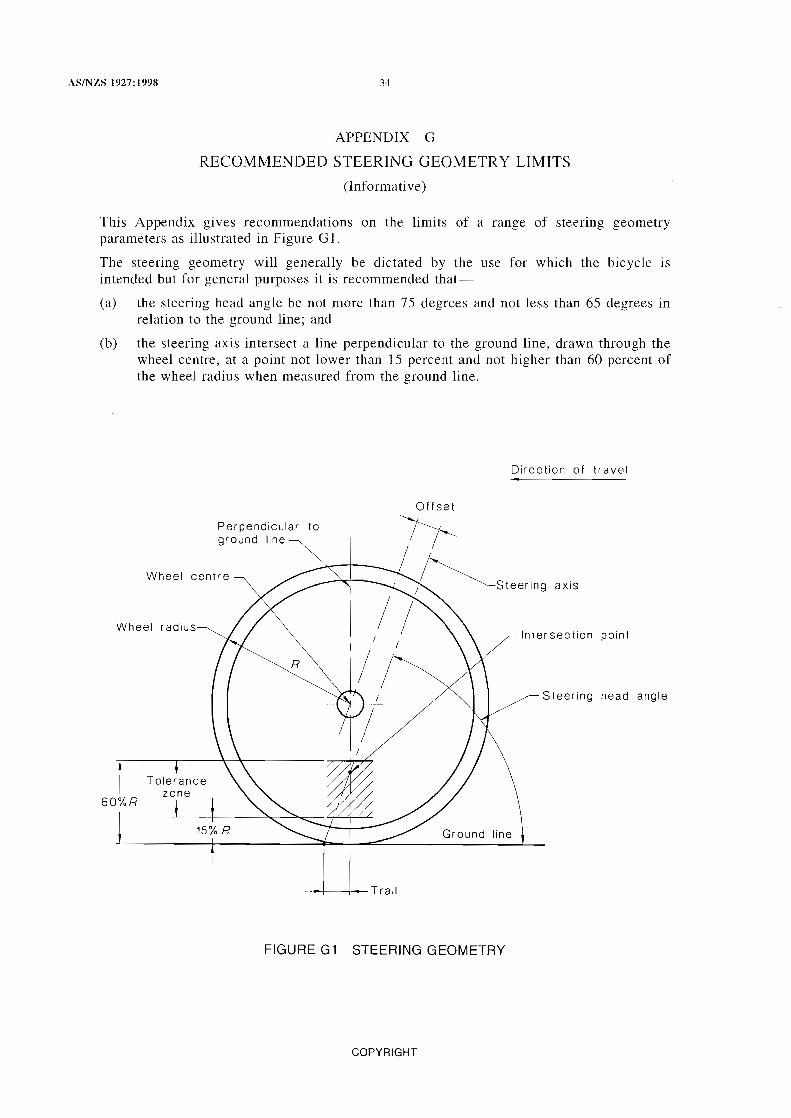
This Appendix gives recommendations on the limits of a range of steering geometry parameters as illustrated in Figure G 1.
The steering geometry will generally be dictated by the use for which the bicycle is intended but for general purposes it is recommended that-
(a) the steering head angle be not more than 75 degrees and not less than 65 degrees in relation to the ground line; and
(b) the steering axis intersect a line perpendicular to the ground line, drawn through the wheel centre, at a point not lower than 15 percent and not higher than 60 percent of the wheel radius when measured from the ground line.
Perpendicular to ground line
Wheel centre
Wheel radius-
Offset
Direction of travel
axis
Intersection pOint
Steering head angle
\ Ground line
--I--t-Trail
FIGURE G1 STEERING GEOMETRY
COPYRIGHT

J5
APPENDIX H
PERFORMANCE TEST OF BRAKING SYSTEM
(Normative)
AS/NZS 1927:1998
HI SCOPE This Appendix sets alit a method of determining the performance of the braking system of a bicycle.
H2 PRINCIPLE A bicycle is ridden along a test track at a specified velocity and the distance required to completely stop the bicycle using maximum braking is measured. This distance is adjusted for any variations in initial velocity, to give the corrected stopping distance which in turn is adjusted for the mass of the rider to give the calculated stopping distance. The test is carried out under dry conditions only.
H3 TEST BICYCLE The bicycle for this test shall be a bicycle which has been subjected to all relevant tests in Appendix D. There shall be no further brake adjustments between the Appendix D tests and these tests.
H4 APPARATUS
NOTE: Other apparatus may be used provided that it operates within the accuracy tolerances specified.
H4.1 Instrumentation for bicycle The following are required:
(a) A calibrated speedometer or tachometer, accurate to within 5 percent, to indicate the speed at commencement of test run.
(b) Marker systems to provide the means for determining the points at which the brakes are first applied. These systems shall operate to provide a mark on the test surface within 0.025 s from the first movement of the brake lever (for handbrakes) or pedal crank (for back-pedal brakes).
A separate marker system shall be provided for each braking system and each shall be actuated by, and at the start of, handbrake lever movement or pedal crank movement in the braking direction. Both marker systems shall be positioned on the same transverse plane.
H4.2 Test track The test track shall comply with the following requirements:
(a) The gradient shall be not greater than 0.5 percent.
(b) The surface shall be hard, of concrete or fine asphalt, free from loose dirt or gravel.
(c) The test track shall incorporate an electronic speed measuring device (e.g. an interval timer) capable of measuring the speed of the bicycle just prior to the start of braking, to an accuracy of ±2 percent.
(d) The surface shall be dry throughout the test.
(e) The wind speed shall be not greater than 11 km/h.
HS TEST SPEED The speed at which a bicycle is tested shall be as follows:
(a) Bicycles with an equivalent ground speed of 24 km/h or greater in the highest gear ratio at a pedal crank rate of 60 r/min-24 km/h.
(b) Bicycles with an equivalent ground speed of less than 24 km/h in the highest gear ratio at a pedal crank rate of 60 rlmin -16 km/h.
COPYRIGHT
AS/NZS 1927:1998 36
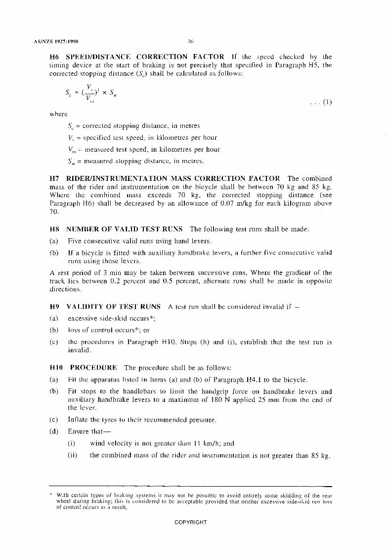
H6 SPEED/DISTANCE CORRECTION FACTOR If the speed checked by the timing device at the start of braking is not precisely that specified in Paragraph H5, the corrected stopping distance (Sc) shall be calculated as follows:
where
v C_')2 X S
V m m
Sc = corrected stopping distance, in metres
V, = specified test speed, in kilometres per hour
Vrn = measured test speed, in kilometres per hour
Sm = measured stopping distance, in metres.
... (1)
H7 RIDER/INSTRUMENTATION MASS CORRECTION FACTOR The combined mass of the rider and instrumentation on the bicycle shall be between 70 kg and 85 kg. Where the combined mass exceeds 70 kg, the corrected stopping distance (see Paragraph H6) shall be decreased by an allowance of 0.07 m/kg for each kilogram above 70.
H8 NUMBER OF VALID TEST RUNS The following test runs shall be made:
Ca) Five consecutive valid runs using hand levers.
(b) If a bicycle is fitted with auxiliary handbrake levers, a further five consecutive valid runs using those levers.
A rest period of 3 min may be taken between successive runs. Where the gradient of the track lies between 0.2 percent and 0.5 percent, alternate runs shall be made in opposite directions.
H9 VALIDITY OF TEST RUNS A test run shall be considered invalid if
(a) excessive side-skid occurs*;
(b) loss of control occurs*; or
(c) the procedures in Paragraph HlO, Steps (h) and 0), establish that the test run is invalid.
HIO PROCEDURE The procedure shall be as follows:
(a) Fit the apparatus listed in Items (a) and (b) of Paragraph H4.1 to the bicycle.
(b) Fit stops to the handlebars to limit the handgrip force on handbrake levers and auxiliary handbrake levers to a maximum of 180 N applied 25 mm from the end of the lever.
(c) Inflate the tyres to their recommended pressure.
Cd) Ensure that-
(i) wind velocity is not greater than 11 km/h; and
(ii) the combined mass of the rider and instrumentation is not greater than 85 kg.
* With certain types of braking systems it may not be possible to avoid entirely some skidding of the rear wheel during braking; this is considered to be acceptable provided that neither excessive side-skid nor loss of control occurs as a result.
COPYRIGHT

37 AS/NZS 1927:1998
(e) Conduct the tests by riding the bicycle over the test course and attain the specified test speed.
Stop pedalling immediately before passing the timing device and apply the brakes immediately after passing the timing device to bring the bicycle to a smooth safe stop remaining in the normal riding position throughout the stop. No limitation is put on the force exerted on the pedal during the testing of a back-pedal brake.
(f) Measure the stopping distance with an accuracy of 0.2 m along the surface of the track from the first mark to a point level with the centre of the marking device on the bicycle.
(g) If necessary, correct the measured stopping distance in accordance with Paragraph H6 and then apply any mass correction allowance in accordance with Paragraph H7.
(h) Consider a test run invalid if the stopping distance calculated in accordance with Step (g) above, exceeds 5.5 m, and if-
(i) the speed at start of braking exceeded the specified test speed by more than 1.5 km/h;
(ii) the distance between the marks for the front* and rear brakes exceeded 1 m in the direction of the bicycle; or
(iii) the rear brake was actuated first as indicated by the marks.
(i) Consider a test run invalid if the stopping distance calculated in accordance with Step (g) above, is not greater than 5.5 m, and if-
(i) the speed at the start of the test is more than 1.5 km/h below the specified test speed; or
(ii) the distance between the point where the speed is confirmed and the mark for the rear brake exceeds 2 m measured along the surface of the track.
NOTE: If the calculated stopping distance exceeds 5.5 m the test run is considered to be valid.
(j) Determine the average calculated stopping distance of five valid test runs for each of the conditions specified in Paragraph H8.
Hll REPORT The following shall be reported:
(a) The average calculated stopping distance of five valid test runs using the handbrake lever(s) and where appropriate, a further five valid test runs using the auxiliary handbrake lever(s).
(b) A reference to this test method, i.e. AS/NZS 1927, Appendix H.
* As the front brake provides a very high percentage of retardation in the prescribed braking tests, it is therefore important that it be applied first. In order that the maximum use of available power is utilized, it is also important that minimal delay occurs in applying the rear brake.
COPYRIGHT

AS/NZS 1927:1998 38
APPENDIX I
STATIC LOAD TEST ON WHEEL
(Normative)
11 SCOPE This Appendix sets out a method of determining the deflection and strength of the wheel assembly of a bicycle,
12 APPARATUS The following apparatus is required:
(a) A means of clamping the hub axle.
(b) A machine capable of applying a force of 178 N.
13 PROCEDURE The procedure shall be as follows:
(a) Support and clamp the wheel in the position as shown in Figure 11.
(b) Apply a force of 178 N at one point on the wheel rim perpendicular to the plane of the wheel for 1 min.
If the wheel hub is offset, apply the force in the sense of the offset as shown in Figure 11.
(c) Record whether failure of any of the components of the wheel occurred.
(d) Measure and record any permanent deformation at the point of application of the force on the rim.
14 REPORT The following shall be reported:
(a) Whether or not failure of any of the components of the wheel occurred.
(b) The permanent deformation, measured at the point of application of the force on the rim, in millimetres.
(c) A reference to this test method, i.e. AS/NZS 1927, Appendix I.
Clamping fixture
Applied force
/ Wheel aSSemblY~
FIGURE 11 STATIC LOAD TEST ON WHEEL
COPYRIGHT

39
APPENDIX J
FRONT FORK TEST
(Normative)
AS/NZS 1927:1998
J1 SCOPE This Appendix sets out a method of determining the energy absorption properties of the front fork of a bicycle.
J2 APPARATUS A suitable device, e.g. a hydraulic test rig, capable of applying the appropriate force, and having a means of indicating the force being applied and the corresponding deflection readings at the point of application of the force, is required.
J3 PROCEDURE The procedure shall be as follows:
(a) Support the fork stem in a 75 ±5 mm V-block with the front of the fork uppermost and anchor it with a nut or some other equivalent means as illustrated in Figure J 1.
(b) A pply a force at the axle attachment point in a direction perpendicular to the centreline of the stem.
(c) Record the load and deflection readings plotted at the point of loading.
Cd) Increase the loading until the deflection in the direction of the loading is such that the energy absorbed by the fork is 40 ± 1 J.
(e) Release the load.
(f) Examine the fork for signs of fracture or permanent deformation. The examination for fractures shall be done at x5 magnification.
J4 REPORT The following shall be reported:
(a) Any evidence of fracture or permanent deformation of the fork.
(b) A reference to this test method, i.e. AS/NZS 1927, Appendix J.
COPYRIGHT

4(j
41 AS/NZS 1927: 1998
APPENDIX K
FORK AND FRAME ASSEMBLY TEST
(Nonnative)
Kl SCOPE This Appendix sets out a method of determining the energy absorption properties of the frame and fork assembly of a bicycle.
K2 TEST SPECIMEN A test specimen of which no component has been llsed for any previous test, shall be used.
K3 APPARATUS The testing device specified in Paragraph 12 of Appendix J is required.
K4 PROCEDURE The procedure shall be as follows:
(a) Anchor the rear wheel axle attachment points.
(b) A pply a force of 890 N to the front axle attachment point towards and in line with the rear wheel axle and from the deflection reading compute the energy absorbed in joules.
(c) Should the energy absorption reading at 890 N be less than 40 J increase the force until this figure is attained.
(d) Release the loading.
(e) Examine the test specimen for any signs of fracture or permanent deformation. The examination shall include the fork steering tube. The examination for fractures shall be done at x5 magnification.
K5 REPORT The following shall be reported:
(a) Any evidence of fracture or permanent deformation of the frame, the fork or the fork steering tube.
(b) A reference to this test method, i.e. AS/NZS 1927, Appendix K.
COPYRIGHT

AS/l\ZS 1927:1998 42
APPENDIX L
HANDLEBAR TESTS
(Normative)
Ll SCOPE This Appendix sets out methods of determining the strength of the handlebar stem and the handlebars and stem assembly of a bicycle.
L2 TEST CONDITIONS All examinations for possible fractures of components shall be performed at x5 magnification.
L3 TORQUE TEST OF HANDLEBAR STEM
L3.1 Apparatus The following apparatus is requhed:
(a) A clamping device.
(b) A test bar.
(c) A means of applying a torque of 108 N.m.
L3.2 Procedure The procedure shall be as follows:
(a) Insert the handlebar stem in the clamp to the minimum insertion depth and tighten securely.
(b) Insert the test bar in the stem.
(c) Apply a torque of 108 N.m to the stem by means of the test bar in a plane parallel to the stem and in the direction of the stem centre-line as indicated in Figure Ll.
(d) Inspect the handlebar stem for evidence of fracture.
L3.3 Report The following shall be reported:
(a) Whether or not there was any visible evidence of fracture of the handlebar stem.
(b) A reference to this test method, i.e. AS/NZS 1927, Appendix L, Paragraph L3.
L4 HANDLEBAR STEM-STATIC LOAD TEST
L4.1 Apparatus The following apparatus is required:
(a) A clamping device.
(b) A means of applying a force of up to 2.1 kN.
L4.2 Procedure The procedure shall be as follows:
(a) Insert the handlebar stem in the clamp to the minimum insertion depth and tighten securely.
(b) Apply a force through the handlebar attachment point in a forward direction and at 45 ±5 degrees from the centre-line as shown in Figure L2, as follows:
(i) For other than children's bicycles . . . . . . . . . . . . . . . . . . . . .. 2 ±O.l kN.
(ii) For children's bicycles ............................. 1 ±O.OS kN.
(c) Inspect the stem for evidence of fracture.
L4.3 REPORT The following shall be reported:
(a) Whether or not there was any visible evidence of fracture of the handlebar stem.
(b) A reference to this test method, i.e. AS/NZS 1927, Appendix L, Paragraph L4.
COPYRIGHT

43
LS STEM-TO-FORK CLAMP TORQUE TEST
LS.l Apparatus The following equipment is required:
(a) A means of securing the front fork.
(b) A means of applying a torque of 47 N.m to the handlebars.
LS.2 Procedure The procedure shall be as follows:
AS/NZS 1927:1998
(a) Secure the handlebars in place on the bicycle in accordance with the manufacturer's instructions.
(b) Clamp the front fork so that it is securely held.
(c) Apply a torque about the axis of the stem, as follows:
(i) For other than children's bicycles ...................... 47 ±5 N.m.
(ii) For children's bicycles ............................. 20 ±2 N.m.
(d) Record any movement of the stem.
LS.3 Report The following shall be reported:
(a) Whether or not there was any movement of the stem.
(b) A reference to this test method, i.e. AS/NZS 1927, Appendix L, Paragraph L5.
L6 STRENGTH TEST OF HANDLEBAR AND STEM ASSEMBLY
L6.1 Apparatus The following equipment is required:
(a) A clamping device.
(b) A means of applying a force of 220 10 N simultaneously at each end of the handlebar.
(c) A means of measuring deflection.
L6.2 Procedure The procedure shall be as follows:
(a) Secure the handlebars in accordance with the manufacturer's instructions either on the bicycle or in the clamping device to the minimum insertion depth. Where a fully assembled bicycle is used, secure the front fork.
(b) Apply a force of 220 ±1O N simultaneously to each end of the handlebars in a direction and at the location that will cause the greatest torque about the handlebars-to-stem clamp.
Where this location occurs at the end of the handlebars, apply the force as near to the end as is practicable but in any case not further than 15 mm from the end (see Figure L3).
NOTE: According to the shape of the handlebar, the forces might be applied in a direction different from that illustrated.
(c) Measure the deflection along the lines of the applied force.
L6.3 Report The following shall be reported:
(a) Whether or not there was any movement of the handlebars related to the stem.
(b) Any evidence of visible fracture of the handlebars or stem assembly.
(c) The residual deflection.
(d) A reference to this test method, i.e. AS/NZS 1927, Appendix L, Paragraph L6.
COPYRIGHT

AS/NZS 1927:1998
Applied force
44
Applied force
~ 350 mm
Clamping fixture
--r--2~~ --t-i--L±l-IJ-".;- ~ bar ~~'::j
Centre of jOint
Min,
FIGURE L 1 TORQUE TEST ON HANDLEBAR STEM
Clamping
fixture\ / " Applied
",-orce
Min, inC:-\ > -,---th _' _l_lj /
~45'
Stem
, r
Handlebar or test bar
FIGURE L2 STATIC LOAD TEST ON HANDLEBAR STEM
COPYRIGHT

Applied force
t I
Clamping
block
FIGURE L3 TORQUE
45
Min. insertion
dep th
Applied
force
J
I
ON HANDLEBAR/STEM ASSEMBL Y
COPYRIGHT
AS/NZS 1927:1998

AS/NZS 1927: 1998 46
APPENDlX M
IMPACT TEST OF PEDAL
(Normative)
Ml SCOPE This Appendix sets out a method of determining the ability of a bicycle pedal axle to withstand impact.
M2 APPARATUS The following apparatus is required:
(a) A mass of 16 +0.25, -0 kg having a circular base of diameter 70 ±5 mm.
(b) A test rig which provides the following:
(i) A means of rigidly clamping a pedal crank in a vertical plane.
(ii) A means, with a suitable release mechanism, of suspending the mass 500 mm directly above the centre of the pedal surface.
(iii) A guard around the impact area which does not impede the fall.
Other apparatus capable of subjecting the crank and pedal assembly to an impact energy of 78.4 J may be used.
M3 PROCEDURE The procedure shall be as follows:
(a) Mount the pedal crank assembly on the rig as shown in Figure M I with the pedal in the horizontal plane.
(b) Suspend the mass from the release mechanism 500 mm above the pedal surface.
(c) Release the mass.
(d) If the axle does not break away from the crank repeat Steps (a) to (c).
M4 REPORT The following shall be reported:
(a) Whether or not the pedal shaft broke away from the crank and if so, whether it occurred on the first or second impact.
NOTE: A bent or partially fractured shaft is not considered to be a failure, and would not necessarily be reported.
(b) A reference to this test method, i.e. AS/NZS 1927, Appendix M.
COPYRIGHT

Crank~
'"
Steel block
47
mechanism
FIGURE M1 TYPICAL IMPACT TEST RIG
COPYRIGHT
AS/NZS 1927:J998
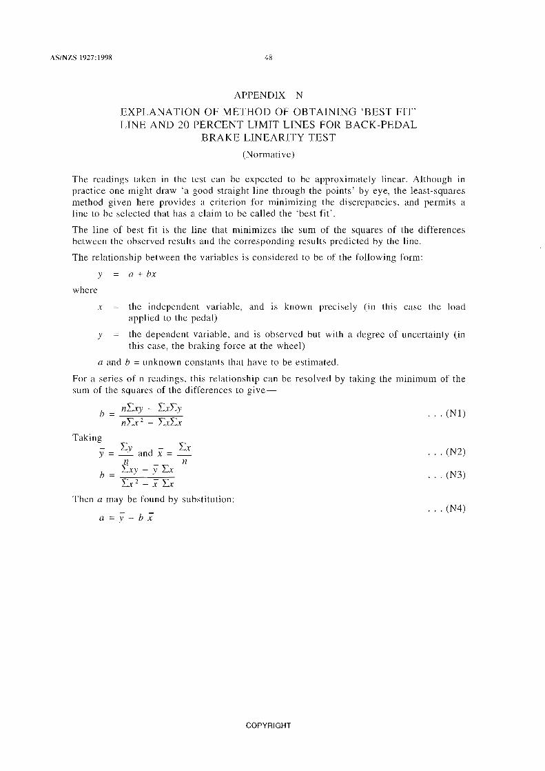
AS/NZS 1927:199& 48
APPENDIX N
EXPLANATION OF METHOD OF OBTAINING 'BEST FIT' LINE AND 20 PERCENT LIMIT LINES FOR BACK-PEDAL
BRAKE LINEARITY TEST
(Normative)
The readings taken in the test can be expected to be approximately linear. Although in practice one might draw 'a good straight line through the points' by eye, the least-squares method given here provides a criterion for minimizing the discrepancies, and permits a line to be selected that has a claim to be called the 'best fit'.
The line of best fit is the line that minimizes the Slim of the squares of the differences between the observed results and the corresponding results predicted by the line.
The relationship between the variables is considered to be of the following form:
where
y = a + bx
x the independent variable, and is known precisely (in this case the load applied to the pedal)
v the dependent variable, and is observed but with a degree of uncertainty (in this case, the braking force at the wheel)
a and b unknown constants that have to be estimated.
For a series of n readings, this relationship can be resolved by taking the minimum of the sum of the squares of the differences to give-
b = nLxy - LXL)' · .. (Nl)
Taking - Lv Lx y = _~ and x = . n n
· .. (N2)
b = Lx)' )' Lx Lx 2
X Lx · .. (N3)
Then a may be found by substitution:
a=y-bx · .. (N4)
COPYRIGHT

49 AS/NZS 1927:1998
Example:
The following four values of x and yare noted during a test, from which
LXy, -2, .t and yare calculated as shown:
x y No. (pedal force) (bnlking force)
N
1 90
2 150
3 230
4 300
LX = 770 ~t = 192.5
128 900 - (147.5 x 770)
0.606
a=y-bx 147.5 (0.606 x 192.5)
30.8
The line of best fit is therefore-
y 30.8 + 0.606x
and the ± 20 percent limit lines are-
80 YI = _ (30.8 + 0.606x)
ower 100
= 24.64 + 0.485x
80 Ylower = 100 (30.8 + 0.606x)
= 36.96 + 0.727x
N
90
120
160
220
590 y 147.5
The results are shown graphically in Figure N 1.
COPYRIGHT
xy x- 2
8 100 8 100
18000 22500
36 800 52900
66 000 90 000
= 128900 Lx-2 173500

AS/NZS 1927:1998 50
250
200
z w-0 IT 0 LL
150 CJ ~ ~ <t IT m
100
50
/
/ V
/ v L ~ Line of best fit~ /
+20% limit\ / ~ V /
/ lY V ~ V
/
/ V V V
/ /' ~
V vA ~ V \
~-20% / / /
limit
7 /' V /
V 100 150 200 250 300
PEDAL FORCE, N
FIGURE N1 TYPICAL GRAPH OF PEDAL FORCE vs BRAKING FORCE, SHOWING 'BEST FIT LINE' AND 20 PERCENT LIMIT LINES
COPYRIGHT


Standards Australia
Standards Australia is an independent company, limited by guarantee, which prepares and publishes most of the voluntary technical and commercial standards used in Australia. These standards are developed through an open process of consultation and consensus, in which all interested parties are invited to participate. Through a Memorandum of Understanding with the Commonwealth government, Standards Australia is recognized as Australia's peak national standards body.
Standards New Zealand
The first national Standards organization was created in New Zealand in 1932. The Standards Council of New Zealand is the national authority responsible for the production of Standards. Standards New Zealand is the trading arm of the Standards Council established under the Standards Act 1988.
Australian/New Zealand Standards
Under a Memorandum of Understanding between Standards Australia and Standards New Zealand, Australian/New Zealand Standards are prepared by committees of experts from industry, governments, consumers and other sectors. The requirements or recommendations contained in published Standards are a consensus of the views of representative interests and also take account of comments received from other sources. They reflect the latest scientific and industry experience. Australian/New Zealand Standards are kept under continuous review after publication and are updated regularly to take account of changing technology.
International Involvement
Standards Australia and Standards New Zealand are responsible for ensuring that the Australian and New Zealand viewpoints are considered in the formulation of international Standards and that the latest international experience is incorporated in national and Joint Standards. This role is vital in assisting local industry to compete in international markets. Both organizations are the national members of ISO (the International Organization for Standardization) and IEC (the International Electrotechnical Commission).
Visit our Web sites
www.standards.org.au www.standards.co.nz

D STANDARDS
NEW ZEALAND P AEAEWA A O TE AAOA