As-i Addressing Unit Manual 3330772-02DS01 En
21
GWA 4NEB 333 0772-02 DS 01 Last update: 19 April 2011 Order No.: 3ZX1012-0RK10-4AC1 AS-Interface addressing unit V 3.0 3RK1904-2AB02 Operating Instructions English s Table of contents Read and understand these instructions before installing, operating, or maintaining the equipment. Note the connection diagrams in the appendix for addressing of AS-i slaves and for performing diagnostics on an AS-i system. NOTICE If the display shows the battery sign " ", new batteries must be installed. Disconnect the device from the AS-i bus before opening it. When a battery is replaced, the configuration data saved in the addressing unit will be lost. WARNING A change between plant states in an ongoing process can result in death or equipment damage, if malfunctions or program errors occur. Make sure that hazardous situations cannot occur before you execute functions such as Data, Parameters, etc. 1. Overview and purpose . . . . . . . . . . . . . . . . . . . . . . . . . . . . . . . . . . . . . . . . . . . . . . . . . . . . . . . . . . . . . . . . . . . . . . . . . . . . . . 2 2. Operator control and display elements . . . . . . . . . . . . . . . . . . . . . . . . . . . . . . . . . . . . . . . . . . . . . . . . . . . . . . . . . . . . . . . . . 3 3. Description of function . . . . . . . . . . . . . . . . . . . . . . . . . . . . . . . . . . . . . . . . . . . . . . . . . . . . . . . . . . . . . . . . . . . . . . . . . . . . . 4 OFF . . . . . . . . . . . . . . . . . . . . . . . . . . . . . . . . . . . . . . . . . . . . . . . . . . . . . . . . . . . . . . . . . . . . . . . . . . . . . . . . . . . . . . . . . . . 4 Memory . . . . . . . . . . . . . . . . . . . . . . . . . . . . . . . . . . . . . . . . . . . . . . . . . . . . . . . . . . . . . . . . . . . . . . . . . . . . . . . . . . . . . . . . 4 ASI V= . . . . . . . . . . . . . . . . . . . . . . . . . . . . . . . . . . . . . . . . . . . . . . . . . . . . . . . . . . . . . . . . . . . . . . . . . . . . . . . . . . . . . . . . . 5 ADDR . . . . . . . . . . . . . . . . . . . . . . . . . . . . . . . . . . . . . . . . . . . . . . . . . . . . . . . . . . . . . . . . . . . . . . . . . . . . . . . . . . . . . . . . . 6 ADDR+MEM . . . . . . . . . . . . . . . . . . . . . . . . . . . . . . . . . . . . . . . . . . . . . . . . . . . . . . . . . . . . . . . . . . . . . . . . . . . . . . . . . . . . 7 Profile . . . . . . . . . . . . . . . . . . . . . . . . . . . . . . . . . . . . . . . . . . . . . . . . . . . . . . . . . . . . . . . . . . . . . . . . . . . . . . . . . . . . . . . . . 7 Data . . . . . . . . . . . . . . . . . . . . . . . . . . . . . . . . . . . . . . . . . . . . . . . . . . . . . . . . . . . . . . . . . . . . . . . . . . . . . . . . . . . . . . . . . . 9 Parameters . . . . . . . . . . . . . . . . . . . . . . . . . . . . . . . . . . . . . . . . . . . . . . . . . . . . . . . . . . . . . . . . . . . . . . . . . . . . . . . . . . . . 12 ASIsafe . . . . . . . . . . . . . . . . . . . . . . . . . . . . . . . . . . . . . . . . . . . . . . . . . . . . . . . . . . . . . . . . . . . . . . . . . . . . . . . . . . . . . . . 14 CTT2 . . . . . . . . . . . . . . . . . . . . . . . . . . . . . . . . . . . . . . . . . . . . . . . . . . . . . . . . . . . . . . . . . . . . . . . . . . . . . . . . . . . . . . . . . 15 4. Maintenance . . . . . . . . . . . . . . . . . . . . . . . . . . . . . . . . . . . . . . . . . . . . . . . . . . . . . . . . . . . . . . . . . . . . . . . . . . . . . . . . . . . . . 16 5. Technical data . . . . . . . . . . . . . . . . . . . . . . . . . . . . . . . . . . . . . . . . . . . . . . . . . . . . . . . . . . . . . . . . . . . . . . . . . . . . . . . . . . . 17 6. System messages . . . . . . . . . . . . . . . . . . . . . . . . . . . . . . . . . . . . . . . . . . . . . . . . . . . . . . . . . . . . . . . . . . . . . . . . . . . . . . . . 18 7. Order numbers . . . . . . . . . . . . . . . . . . . . . . . . . . . . . . . . . . . . . . . . . . . . . . . . . . . . . . . . . . . . . . . . . . . . . . . . . . . . . . . . . . . 19 Appendix . . . . . . . . . . . . . . . . . . . . . . . . . . . . . . . . . . . . . . . . . . . . . . . . . . . . . . . . . . . . . . . . . . . . . . . . . . . . . . . . . . . . . . . . . . 20 !
Transcript of As-i Addressing Unit Manual 3330772-02DS01 En

GWA 4NEB 333 0772-02 DS 01 Last update: 19 April 2011
Order No.: 3ZX1012-0RK10-4AC1
AS-Interface addressing unit V 3.0 3RK1904-2AB02
Operating Instructions English
s
Table of contents
Read and understand these instructions before installing, operating, or maintaining the equipment. Note the connection diagrams in the appendix for addressing of AS-i slaves and for performing diagnostics on an AS-i system.
NOTICE
If the display shows the battery sign " ", new batteries must be installed. Disconnect the device from the AS-i bus before opening it. When a battery is replaced, the configuration data saved in the addressing unit will be lost.
WARNING
A change between plant states in an ongoing process can result in death or equipment damage, if malfunctions or program errors occur.Make sure that hazardous situations cannot occur before you execute functions such as Data, Parameters, etc.
1. Overview and purpose . . . . . . . . . . . . . . . . . . . . . . . . . . . . . . . . . . . . . . . . . . . . . . . . . . . . . . . . . . . . . . . . . . . . . . . . . . . . . .22. Operator control and display elements . . . . . . . . . . . . . . . . . . . . . . . . . . . . . . . . . . . . . . . . . . . . . . . . . . . . . . . . . . . . . . . . .33. Description of function . . . . . . . . . . . . . . . . . . . . . . . . . . . . . . . . . . . . . . . . . . . . . . . . . . . . . . . . . . . . . . . . . . . . . . . . . . . . .4
OFF . . . . . . . . . . . . . . . . . . . . . . . . . . . . . . . . . . . . . . . . . . . . . . . . . . . . . . . . . . . . . . . . . . . . . . . . . . . . . . . . . . . . . . . . . . .4 Memory . . . . . . . . . . . . . . . . . . . . . . . . . . . . . . . . . . . . . . . . . . . . . . . . . . . . . . . . . . . . . . . . . . . . . . . . . . . . . . . . . . . . . . . .4 ASI V= . . . . . . . . . . . . . . . . . . . . . . . . . . . . . . . . . . . . . . . . . . . . . . . . . . . . . . . . . . . . . . . . . . . . . . . . . . . . . . . . . . . . . . . . .5 ADDR . . . . . . . . . . . . . . . . . . . . . . . . . . . . . . . . . . . . . . . . . . . . . . . . . . . . . . . . . . . . . . . . . . . . . . . . . . . . . . . . . . . . . . . . .6 ADDR+MEM . . . . . . . . . . . . . . . . . . . . . . . . . . . . . . . . . . . . . . . . . . . . . . . . . . . . . . . . . . . . . . . . . . . . . . . . . . . . . . . . . . . .7 Profile . . . . . . . . . . . . . . . . . . . . . . . . . . . . . . . . . . . . . . . . . . . . . . . . . . . . . . . . . . . . . . . . . . . . . . . . . . . . . . . . . . . . . . . . .7 Data . . . . . . . . . . . . . . . . . . . . . . . . . . . . . . . . . . . . . . . . . . . . . . . . . . . . . . . . . . . . . . . . . . . . . . . . . . . . . . . . . . . . . . . . . .9 Parameters . . . . . . . . . . . . . . . . . . . . . . . . . . . . . . . . . . . . . . . . . . . . . . . . . . . . . . . . . . . . . . . . . . . . . . . . . . . . . . . . . . . .12 ASIsafe . . . . . . . . . . . . . . . . . . . . . . . . . . . . . . . . . . . . . . . . . . . . . . . . . . . . . . . . . . . . . . . . . . . . . . . . . . . . . . . . . . . . . . .14 CTT2 . . . . . . . . . . . . . . . . . . . . . . . . . . . . . . . . . . . . . . . . . . . . . . . . . . . . . . . . . . . . . . . . . . . . . . . . . . . . . . . . . . . . . . . . .15
4. Maintenance . . . . . . . . . . . . . . . . . . . . . . . . . . . . . . . . . . . . . . . . . . . . . . . . . . . . . . . . . . . . . . . . . . . . . . . . . . . . . . . . . . . . .165. Technical data . . . . . . . . . . . . . . . . . . . . . . . . . . . . . . . . . . . . . . . . . . . . . . . . . . . . . . . . . . . . . . . . . . . . . . . . . . . . . . . . . . .176. System messages . . . . . . . . . . . . . . . . . . . . . . . . . . . . . . . . . . . . . . . . . . . . . . . . . . . . . . . . . . . . . . . . . . . . . . . . . . . . . . . .187. Order numbers . . . . . . . . . . . . . . . . . . . . . . . . . . . . . . . . . . . . . . . . . . . . . . . . . . . . . . . . . . . . . . . . . . . . . . . . . . . . . . . . . . .19Appendix. . . . . . . . . . . . . . . . . . . . . . . . . . . . . . . . . . . . . . . . . . . . . . . . . . . . . . . . . . . . . . . . . . . . . . . . . . . . . . . . . . . . . . . . . .20
!

2 Order No.: 3ZX1012-0RK10-4AC1
1 Overview and purposeFor convenient commissioning and diagnostics of an AS-i bus system, the addressing unit offers the following functions:• Reading out and setting of slave address 0 to 31 or 1A to 31A, 1B to 31B for all AS-Interface slaves• To prevent double addressing, previously used addresses can be saved and blocked.• Measurement of the voltage on the AS-Interface cable and measurement of the AS-i slave operational current• Test of the input and output data of digital and analog slaves according to AS-Interface Specification V3.0, including safety-related input slaves• Setting of parameters of a slave for test purposes and reading back of parameter echo• Reading out of slave profile (IO, ID, ID2)• Reading out and setting of the ID1 code• Reading out of data objects Identifier and Diagnosis for CTT2 slaves• Reading out of safety code sequences of safety-related input slaves (ASIsafe)• Reading and writing of cyclic input and output channels of CTT2 slaves• Saving of complete network configurations (profiles of all slaves) as addressing aid
Reading out and setting of slave addresses for AS-Interface slaves The main purpose of the addressing unit is to assign an address to each AS-Interface slave during commissioning.The device detects a connected slave module or a complete AS-i network and displays the slave addresses found in the LCD display. In the as-delivered condition, a new slave has address 0.To be able to participate in data exchange with the master, every AS-i Slave must be assigned an address not equal to zero.Slaves with standard addressing use the address range 1...31. Slaves with extended addressing use the address range 1A...31A, 1B...31B.The addressing unit detects the addressing type automatically.An address must not be assigned more than once on one AS-i bus system. If a slave with standard address exists, the same address value cannot be used for slaves with extended address. If a slave with extended address uses an address value as an A-address, another slave with extended address can use the same address value as a B-address.
Examples: If there is an existing slave with standard address 1, the addresses 1A and 1B are no longer available for slaves with extended address. If there is an existing slave with extended address 2A, a slave with extended address 2B can also be used. So that addresses are not inadvertently assigned more than once, the addressing unit can save the previously set addresses and only offer unused addresses for selection for new slaves.Resetting to address 0 is also possible.
Connection of an AS-Interface slave to the addressing unitIn order to set the address of a slave, the addressing cable enclosed with the addressing unit is connected to the M12 socket of the device, and the hollow plug is inserted in the addressing socket of the slave module. When the hollow plug is inserted, the slave module is automatically discon-nected from any connected AS-i bus cable. The slave module is supplied with power from the addressing unit. In switch position ADDR or ADDR+MEM, pressing the RETURN key displays a suggested address that can be changed with the Up/Down keys and confirmed with the RETURN key. Slave modules with M12 connector instead of the addressing socket can be connected with a commercially available M12 connecting cable.
Connection of the addressing unit to an AS-i bus systemAlternatively, the M12 socket of the device can be connected to multiple slaves with an AS-i bus cable. The addressing unit lists all found addresses in the address field of the LCD display. The Up/Down keys can be used to select the address to be edited (flashing address) and the RETURN key can be used to confirm. Because in this case all slave modules must be supplied with operational current, an AS-i power supply or an AS-i data decoupling unit plus power supply must be connected to the AS-i bus cable. The addressing unit is suitable for standard AS-i networks (rated voltage 30 V) and AS-i Power 24 V networks (minimum operating voltage on the AS-i bus cable of 19 V).
NOTEFinding the address of a module if several slaves are connected:When the addressing unit is connected to an AS-i bus system, the rotary switch can be set to Data, and the Up/Down keys can be used to run through the existing addresses. The addressing unit activates exactly one slave on the bus at a time. The address flashes in the address field of the display on the addressing unit, and the assigned AS-i slave indicates the activation status on the module (e.g., AS-i LED: green, Fault LED: Off). In this way the address of the module can be determined easily without having to use the addressing socket of the module.

Order No.: 3ZX1012-0RK10-4AC1 3
2 Operator control and display elements
Meaning of the additional information in the main display:
For additional system messages, see Chapter 6 System messages.
NOTEThe addressing cable is operational even without being screwed into place in the M12 socket of the addressing unit.
Bin Display as binary numberHex Display as hexadecimal number (otherwise display as decimal number)IN Input valueEDIT Output value / Edit modeChannel Channel number (e.g., for analog module)PFF I/O fault flag (reported by slave)IO.ID.ID2 Profile codesID1 ID1 codeA or B Address detection for slave with extended addressingA or V Display of amperes or volts
Battery voltage low
1 Main display with 8 digits and additional information This symbol represents the information on the 7-segment display
2 Address field: Display of assigned AS-i addresses
3 RETURN / Input confirmation
4 Up / Increase value
5 Down / Decrease value
6 Escape / Cancel
Key combinations:
7 Rotary switch for function selection
8 M12 sockets for connection of the AS-i slaves
Edit function / Write outputs
Device setting
888
↵
ESC
+EDIT
+MODE
1
2
3
456
7
8

4 Order No.: 3ZX1012-0RK10-4AC1
3 Description of functionIn the following, the function of the addressing unit is presented in detail for each position of the rotary switch. The operator input on the device is shown in the left column, and the action is explained in the text on the right.
The following basic rule applies to the operator input:
Escape / Cancel to cancel the function
Down / Up to select
RETURN to confirm a selection
Simultaneously pressing the Up and RETURN keys (EDIT key combination) starts a function for writing or editing values or outputs
Simultaneously pressing the Down/Up keys (MODE key combinations) starts a function for changing settings for the operator input or for the behavior of the addressing unit.
The last used address of a slave is saved in the addressing unit and used as a default value when a change is made to a different operator input function.
In order to return to the initial display (memorY, AddrES, Add.MEM, etc.) of a function selected with the rotary switch, it may be necessary to press more than once. To exit the initial display, the RETURN key must be pressed or the rotary switch operated.
OFF In the OFF switch position, the addressing unit is switched off manually.
To conserve the batteries, the device switches off automatically if a user operation (key, rotary switch) does not take place for approximately 5 minutes. If a cyclical data exchange with AS-i slaves is active (read inputs, write outputs in Data or CTT2 position), the device switches off after approx. 1 minute without a user operation in order to limit the higher power consumption during bus access. The device is switched on again after the automatic shutdown by actuating the rotary switch or RETURN.
Memory memorY : Erase, copy, store, and load memoryThe addressing unit has 5 configuration memories (No. 0 to 4). Memory 0 is used as work memory. The AS-i addresses and associated profiles found in switch position ADDR+MEM are stored here.If the device is used on a new AS-i system, memory 0 must be cleared (CLEAR), in order to release previously used addresses for the ADDR+MEM function.Memory 0 can be stored in another memory (1 to 4) (STORE) and recalled again (RECALL).
memorY The switch position recognizes the following subfunctions, which are selected via the Up/Down keys and started with RETURN.
CLEAR COPY STORE RECALL
If one of the subfunctions has been started, the address field of the LCD display shows which addresses are stored in the selected memory.
CLEAR CLEAr RETURN Clear memory content0 CLEAr? 1 CLEAr? ... 4 CLEAr? Clr.All?
Confirm clearing of the memory with selected number or clearing of all memories (ClearAll) with RETURN.An empty memory is indicated as EMPty (empty).
CoPy CoPy RETURN Transfer saved configuration to AS-i systemIn "COPY" mode, all addresses of a saved configurationcan be transferred one after the other to individual slaves of a new AS-i system. This means that an existingsystem configuration can be copied to an identical second system.First select a memory that you want to transfer.COPY 0 COPY 1 ... COPY 4
ESC
↵
+EDIT
+MODE
ESC
↵
↵
↵
↵

Order No.: 3ZX1012-0RK10-4AC1 5
NOTICEThe memory is cleared during the COPY function. Store the memory content in another memory beforehand in order to be able to use it again later.
CoPy X Confirm the selection of the memory with RETURN.The device indicates rEAdY in the display and waits until the RETURN key is pressed (or cancel with ESC).The device now checks (SEArcH) to determine whether a slave is connected whose profile matches a profile stored in the memory.
Possible responses to memory transfer: EMPty : There are no addresses stored; the memory is empty (empty). no ASI : No slave was found.not.EqU : A matching slave was not found (not equal).no.CoPy : There are several slaves connected; COPY is not possible.SEt to : A slave was found whose profile matches one or more saved address(es). Use the Up/Down buttons to select a flashing address and confirm with RETURN. The address will be written to the slave (ProG). clrAdr then appears in the display. With RETURN, the address is cleared from the memory (so that it cannot be assigned to any other slave); with ESC the address remains in the memory (and can be assigned again). The device then indicates rEAdY in the display and waits again for the RETURN key, see above.With the key, the function can be canceled at any point. Since the memory status is retained, it is possible to continue later.
StorE StorE RETURN Store memory 0 to memories 1 to 40 to 1 ? 0 to 2 ? ... 0 to 4 ?
Confirm storing (copying) of work memory 0 to memories 1 to 4 with RETURN.
If content is identical, 0 == 1 will be output, for example.
rECALL rECALL RETURN Reload memories 1 to 4 to memory 0 / Check of memory content No. 0
1 to 0 ? 2 to 0 ? ... 4 to 0 ?
Confirm loading (copying) of memories 1 to 4 to memory 0 with RETURN.If content is identical, 1 == 0 will be output, for example.
For display 0==0 to 4==0, the content of work memory 0 can be checked by pressing RETURN.With Up/Down, the saved address is selected (flashing); the corresponding profile (IO.ID.ID2) and the ID1 value appear in the main display. Exit the check function with ESC.
memory The memory allocation is dynamically managed by the device. In the memory initial display, the amount of free memory space can be determined by pressing ESC.ESC FrE. 98: Display of free memory space in % (here: 98% free memory)
The settings for the operator input on the addressing unit (e.g., display output as hex value or decimal value) are stored in a sepa-rate internal memory.All memory contents are retained even if the device is switched off. However, the content is lost when the battery is replaced.
ASI V= Display of AS-i voltage, AS-i current consumption and voltage of the device battery
AS1 26.0 V : External AS-i voltage presentAS1 0 V 0.025 A: If no external AS-i voltage is applied at the slaves, the current consumption of the slaves is displayed.Switched-off AS-i power supplies and AS-i master must be disconnected from the bus! In the case of slaves with higher current consumption (e.g., analog modules), use of an external AS-i power supply is recom-mended.Change to display of the battery voltage (example: bAt 5.6 V)Pressing ESC again returns you to the display of the AS-i voltage or AS-i current consumption
↵
↵
ESCESC
↵
↵
↵
↵
ESC
888
ESC

6 Order No.: 3ZX1012-0RK10-4AC1
ADDR Addressing without saving of bus configurationSlaves can be selected and readdressed here.A brief introduction can be found in Chapter 1 Overview and purpose.
Search : Search all slave addresses on the bus (Search). All addresses found are displayed in the address field.
vSE X : Select slave address for readdressing (Use address X; X = 0..31, A/B)
Confirm selectionIf only 1 slave is connected, the slave is selected automatically (step vSE X omitted).Slave address flashes in address field set X : The current address is displayed (Set X)Select new address for current slave if necessary, only addresses that are compatible with the slave type are available for selec-tion.Via the MODE key combination for the SET X display, a direct switch can be made from A-address to B-address (and vice versa) for slaves with extended addressing.If a slave with address 0 was found, this slave is selected automatically and the next free address after the last programmed address is suggested.Via the MODE key combination for the Addr initial display, the search for free addresses (addressing sequence) can be adapted for slaves with extended addressing:1 ADr.SEq : Search sequence 1A, 2A, 3A, ...31A, 1B, 2B, 3B, 31B2 ADr.SEq : Search sequence 1A, 1B, 2A, 2B, ... 31A, 31B
→ ProG : New address X is transferred to the slave → Display AS 1 X
→ Back to the AddrES initial display
→ SEARCH
NOTE
If two or more modules with identical slave address are discovered on the AS-i bus, the device displays dbl.add. The relevant address flashes in the address field; a change in the address is not possible. In certain situations, dbl.Add may also be displayed if the device could not explicitly decode the AS-i communication.
NOTE
It is not possible to change addresses not equal to 0 if a slave with address 0 is connected.
NOTE
When a new AS-i system is commissioned, several new slaves (with address 0) must not be simultaneously connected to the addressing unit. The slaves with address 0 must be connected one after the other and readdressed.
NOTE
The display 0A in the address field indicates that a slave with extended addressing (A/B slave) with address 0 was found.
888
↵
888
+MODE
↵
ESC
↵
Order No.: 3ZX1012-0RK10-4AC1 7
ADDR+MEM Addressing with saving of the bus configurationFunction same as ADDR, but with saving of all addresses discovered on the AS-i system or newly programmed in the work mem-ory (configuration memory No. 0, see also Memory). The saved addresses are marked as "already in use" and are no longer avail-able for addressing. This prevents multiple assignment of the same address to several slaves of an AS-i system (double addressing). When readdressing an existing address to another address, the work memory is also updated, i.e., the previous address is removed from the work memory, while the new address is entered. The address 0 is never entered in the memory.The corresponding profile (IO.ID.ID2) and the ID1 Code are also stored in the work memory for each address.
Before assigning addresses for a new AS-i system, the work memory should be cleared:Press ESC (more than once, if necessary), until the Add.MeM initial display appears in the main display. All addresses contained in the work memory are displayed in the address field. Press the EDIT key combination for the Add.mEm initial display.0 CLEAr?. is displayed and must be confirmed with .Alternatively, clearing can be carried out in the Memory switch position.
NOTEIf the ESC key is pressed for the Add.MEM initial display, the percentage of free memory available in the addressing unit is displayed briefly, e.g., FrE. 98 means 98% free memory.
Profile Reading of the slave profile IO.ID.ID2 and ID1 (can be edited) The profile of a slave describes the basic properties of the slave and is used by the AS-i master for identifying the correct configuration of an AS-i system.The profile consists of IO code, ID code, and ID2 Code (IO.ID.ID2). These 3 values are saved in the slave and cannot be changed. In addition, there is the ID1 code that can be set for many slaves. The meaning of ID1 can be found in the documenta-tion of the slave. Some slaves do not have the ID2 and ID1 codes; a master then works with the substitute values F (hex) for both codes. All codes are 4-bit values with a range of values from 0...F (hex format).In the case of slaves with extended addressing, the highest bit in the ID1 memory is used internally for the ID of the address (A or B), so that the value range for ID1 is limited to 0...7. Since some masters figure in the address identifier in the representation of ID1, the value range for ID1 shifts to 8...F (hex) in this case for slaves with B-address. The addressing unit can switch between the two types of representation.
search: Search for all slave addresses on the bus,The first address found flashes, and the corresponding profile is displayed.Select slave
Representation of ID1 in the case of slaves with extended addressing:
By pressing the MODE key combination, the display of the value range of ID1 for slaves can be changed:Option 1) ID1 of A/B slaves is always displayed in the range from 0...7. Option 2) ID1 is displayed in the range 8...F for B-addresses (i.e., addition of 8). A decimal point is shown before ID1 for identification.
The changeover is only possible, if a slave with A-address or B-address is selected; this also applies in EDIT mode (see below).In the case of slaves with standard addressing, ID1 is always displayed in the range 0...F.
Changing of ID1 (if present):Select EDIT level, address flashes, slave profile is displayed
If necessary select new value for ID1
New value for ID1 flashes in the main display→ PrOG: New value is transferred to the slave (program) Value no longer flashes after successful programming of the slave.PrG.Err: Error message if the slave does not permit changing of ID1.
888
888
+MODE
+EDIT
888
↵
8 Order No.: 3ZX1012-0RK10-4AC1
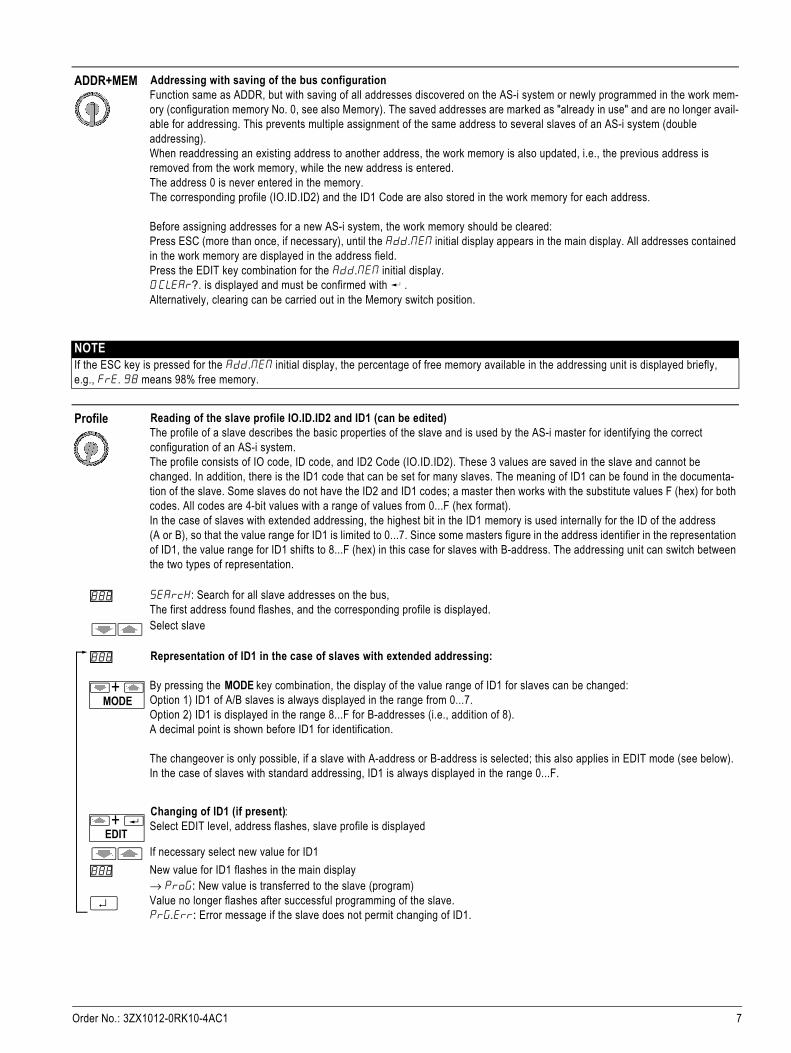
Reading of the data objects ID and Diagnosis - only for CTT2 slaves (profiles 7.5.5 / 7.A.5 / B.A.5)search: Search for all slave addresses on the bus,The first address found flashes; the corresponding profile is displayed (as described above).Select slaveIf a CTT2 slave is selected (i.e., profile 7.5.5 / 7.A.5 / B.A.5), the basic data of the CTT2 data objects ID and Diagnosis are read out and displayed after the RETURN key is pressed (Ctt2 can be read in the display briefly). Refer to the description of the slave to determine the extent to which the data objects are relevant for the user. The first 5 bytes (No. 0...4) are read out from the object ID, and byte No. 0 from the Diagnosis object. The display occurs sequen-tially in hexadecimal display by pressing RETURN multiple times.Example:
Display of the manufacturer ID / Vendor ID (bytes 0 and 1 of the object ID / Index 0)
0 1d.002a here: Vendor-ID_high = 00, Vendor-ID_low = 2A (hex)Vendor ID 002A: Siemens AG
Display of the manufacturer ID / Device ID (bytes 2 and 3 of the object ID / Index 0)
2 1d.0901 here: Device-ID_high = 09, Device-ID_low = 01 (hex)Device ID 0901: M200D AS-i Standard motor starter
Display of the configuration identifier / Config ID (byte 4 of the object ID / Index 0)
4 1d. BB here: Config ID = BB (hex)Config ID BB: 2 output channels, 2 input channels, data width 16 bits, transparent valuesMeaning of Config ID:Config ID defines type, number, and data width of the cyclic CTT2 channels of the slave inoutput direction (high nibble, bits 8-15) and input direction (low nibble, bits 0-7 of Config ID).Nibble values 0 ... 7: Channel type analog valueNibble values 8 ... F: Channel type transparent value (e.g., for a bit-by-bit evaluation)0 or 8: No channel1 or 9: 1 channel with 8-bit data width2 or A: 1 channel with 16-bit data width3 or B: 2 channels each with 16-bit data width4 or C: 3 channels each with 16-bit data width5 or D: 4 channels each with 16-bit data width6, 7 or E, F: Reserved
Display of the standard diagnostic code (byte 0 of the Diagnosis object / Index 1)
0 d1a. 00 here: Standard diagnostic code = 00 (hex)Diagnostic code 00: No faultDiagnostic code FF: General faultDiagnostic code otherwise: See description of the CTT2 slave
Back to initial display
NOTEThe data objects are read out only once from the slave. The complete sequence must be run through once again for an update.
888
↵888
↵888
↵888
↵888
↵

Order No.: 3ZX1012-0RK10-4AC1 9
Data Reading and writing of slave dataThe addressing unit can read the inputs of a slave and control the outputs. Thus, a wiring test can be performed even without an AS-i master/PLC. Both digital and analog values are processed. Also the status of safe input slaves is displayed (only for diagnos-tic purposes, not to be used for safety-related switching actions). Safe outputs cannot be controlled for safety-related reasons.
PFF displayIn the Data function, the status of the I/O fault bit of the slave is also displayed in addition to the input/output data. If the PFF symbol is at the top of the display, the slave signals an I/O fault (Periphery Fault Flag). For the meaning of the I/O fault, refer to the documentation of the slave.search : Search for all slave addresses on the busThe first address found flashesSelect slave
Data behavior for digital slaves:If a digital slave is selected (flashing address), the status of the inputs is read immediately and cyclically updated. The outputs are reset to 0.The MODE key combination switches the display between binary and hexadecimal representation (Symbol "Bin" or "Hex" lights up).As is usual in the number system, the binary digits of the outputs or inputs are incremented starting from the right.
87654321 Bin
Examples: Position right = lowest number of the outputs/inputs; Position left = highest number.
The addressing unit evaluates the profile information of the selected slave and shows a horizontal dash (minus sign) for input/out-put bits in binary display, if the slave does not support the relevant bit. In this case, 4 binary places are displayed, with the follow-ing exception: For digital A/B slaves with 8 inputs and 8 outputs (CTT3 slaves with profile 7.A.A, with extended addressing), 8 binary places are displayed.For writing of output data (EDIT function), the EDIT key combination must be pressed. The text symbol EDIT appears in the upper right area of the display. If the slave does not support any outputs, "no OUt“ (no output) is displayed; the EDIT function is exited with ESC.
EDIT function for binary display ("Bin"):At the start of the EDIT function, all binary output bits initially flash below the Edit symbol. To activate the write function, RETURN must be pressed once.
NOTICEThe data are immediately written to the slave. Make sure that the setting of outputs cannot cause a dangerous situation to occur.
After activating, exactly one output bit flashes, which can now be changed.The RETURN key can be used to advance to the next output bit.With the Up key, the output bit is set (1); with the Down key, the output bit is reset (0).
With the ESC key, all output bits are reset to 0. With a short press you remain in the EDIT function. If the ESC key is pressed lon-ger (approx. 2 s), the EDIT function is exited.In the case of slaves with a maximum of 4 output bits, the state of the inputs can also be monitored in the left area of the display. A decimal point on the display separates the outputs (right) from the inputs (left). The text IN appears above the displayed inputs. A set input (1) is displayed as a short vertical dash; this vertical dash is omitted for a reset input (0). As an aid for counting the inputs, two horizontal dash segments are displayed above the vertical dashes. A dash "hangs" on both sides of a horizontal segment for a set input bit.EDIT function for hexadecimal display ("Hex"):At the start of the EDIT function, the hexadecimal output value 0 is located below the EDIT symbol.
NOTICEMake sure that the setting of outputs cannot cause a dangerous situation to occur.
888
+MODE
+EDIT
ESC
+EDIT
↵
↵
ESC
+EDIT

10 Order No.: 3ZX1012-0RK10-4AC1
Pressing the RETURN key writes the displayed value to the output and changes the flashing display to steady light.With the Up key, the output value in the display increases (+1); with the Down key, the output value in the display decreases (-1). A modified value is displayed as a flashing value and is not written to the output until the RETURN key is pressed.
With the ESC key, the output value is reset to 0. With a short press you remain in the EDIT function. If the ESC key is pressed longer (approx. 2 s), the EDIT function is exited.The status of the inputs can also be monitored in the left area of the display. A decimal point on the display separates the outputs (right) from the inputs (left). The text IN appears above the displayed input value.
Data behavior for safety-related slaves:Safe slaves send their status information coded by means of a code table via the bus cable. The addressing unit decodes the sent information and displays the result in the display. For binary display, a two-digit binary value is located at the far left of the display. This value shows the decoded input status for the two input channels of the safe slave.To the right of this, the undecoded bit information of the inputs is displayed with vertical dashes; see description of monitoring of input states for EDIT function. The code table ensures that the undecoded bit information changes continuously, when an input is connected with a closed contact.For hexadecimal display, the undecoded information of the inputs is always displayed.
NOTICEDo not use the status information of safe inputs displayed on the addressing unit for enabling safety circuits. The decoding by the addressing unit is not carried out in a safety-related manner.
If the safe input slave also has non-safety-related outputs, the outputs can be set as described above for the EDIT function.
NOTICEMake sure that the setting of outputs cannot cause a dangerous situation to occur.
Safety-related outputs of a safe AS-i module cannot be controlled from the addressing unit for safety-related reasons.
↵
↵
ESC

Order No.: 3ZX1012-0RK10-4AC1 11
Data behavior for analog slaves:The MODE key combination switches the display between decimal, hexadecimal (Symbol "Hex"), and percent representation (o
o behind the value).
For the representation in %, the following assignment applies: 0.0% = 0 (dec) = 0 (hex) 100.0% = 27648 (dec) = 6C00 (hex) 118.5 % = 32767 (dec) = 7FFF (hex) (maximum positive value, positive overflow)-100.0% = -27648 (dec) = 9400 (hex)-118.5% = -32768 (dec) = 8000 (hex) (minimum negative value, negative overflow)
NOTICEMake sure that the selected analog slave uses the same assignment of the percentage values.Use only the decimal or hexadecimal representation, if a different assignment is used.
Analog slave with inputs
Confirm selection of the slave addressChannel2: Select input channel number 1...4 of the analog slave
(depending on the slave type)Channel2: 00000 (dec.) Confirm channel number and display input value
Analog slave with outputsno 1n: Slave has no inputs (no Input)EDIT : Activate channel selection; (channel selection is omitted if the analog slave has only 1 output)
Channel2: Select output channel number 1...4 of the analog slave (depending on the slave type)
Channel2: 00000 (dec.) Confirm channel number and display output
After activating, exactly one place in the output value flashes, which can now be changed.The RETURN key can be used to advance to the next place.With the Up key, the place is incremented (+1); with the Down key, the place is decremented (-1).
NOTICEThe data are immediately written to the slave. Make sure that the setting of output values cannot cause a dangerous situation to occur.
ESC key ends the output of output values.1 x ESC : Return to Select output channel2 x ESC : Return to Display no 1n
+MODE
↵
↵
ESC
+EDIT
↵888
↵
ESC

12 Order No.: 3ZX1012-0RK10-4AC1
Parameters PARA : Writing of slave parameters and reading of parameter echoFor activating the data exchange of an AS-i slave (read/write input data/output data), it is necessary that the slave receives a 4-bit parameter set during ramp-up. However, the slave can also receive a parameter set during operation. If the slave receives a parameter set, it responds with a so-called parameter echo. The parameter echo consists of 4 bits with any values, i.e., the content of returned echoes can deviate from the content of the received parameter set.
In the case of slaves with standard addressing, the default value for the parameter is F (hex) or 1111 (bin). In the case of slaves with extended addressing (A/B slaves, ID code: A), the highest bit of the parameter set is not available, i.e., the default value for the parameters is 7 (hex) or 111 (bin) in this case. For some slaves, the operating behavior can be set by changing the parameter bits, e.g. for conversion of the measuring range for analog modules (refer to the operating instructions of the slave).
In the Parameters switch position, the parameters can be changed via the addressing unit.
The set slave parameters are stored temporarily in the addressing unit and output on the display.Reading back of the parameters (4-bit parameter set) from the slave is not possible, on principle. With 0 CLEAr ? in the memorY switch position, the temporarily stored 4-bit parameter sets can be reset to the default values F (hex) or 1111 (bin).
The set parameters are used for the Data function of the addressing unit:Before the input data/output data are transferred, the addressing unit automatically sends the slave the 4-bit parameter set that was set with the Parameters function for the respective slave address.
Because the parameters are not saved retentively in the slave, it loses the parameters sent by the addressing unit (4-bit parameter set) if the addressing unit is disconnected. If present, the AS-i master then sends its parameters to the slave.
Exception:Slaves with profile 7.2 and 7.4 can save a parameter string (data block with several bytes) retentively.The 4-bit parameter set is not available for these slaves. The parameter string can be read from the slave.
search : Search for all slave addresses on the busThe first address found flashesSelect slave
Standard situation: Slaves with 4-bit parameter set
Address flashes. Last set parameters are displayed in hexadecimal or binary display. The parameters are not sent to the slave.
The MODE key combination switches the display between hexadecimal ("hex" symbol) and binary display ("bin" symbol). In the case of slaves with extended addressing, the highest parameter bit is not available.
EDIT : Menu for changing and writing of parameters.
Set new parameter value.
Hex value/binary value flashes in the main display
Transfer parameters to the slave.
eCho. F (hex) / eCho.1111 (bin): The parameter echo returned from the slave is shown in hexadecimal or binary display.
Return to EDIT function with ESC or RETURN.
The EDIT function is exited with ESC.
888
888
+MODE
+EDIT
888
↵888
ESC ↵
ESC

Order No.: 3ZX1012-0RK10-4AC1 13
Special case: Slaves with parameter string (profile 7.2/7.4)
In the case of slaves with profile 7.2 or 7.4, the addressing unit automatically switches the parameter assignment function to parameter string editing.read is displayed briefly while the addressing unit reads out the parameter string from the slave. The parameter string consists of several bytes.The display then outputs the first byte of the parameter string.The byte number XX (decimal) is on the left of the display. The value YY of the byte (hexadecimal) is on the right.
Byte number XX flashes and can be selected.
Select byte number XX; the corresponding byte value YY is immediately displayed.
Byte number XX stops flashing.
Display shows the "EDIT" symbol. The parameter string can be changed. The byte number XX flashes and can be selected.
Select byte number XX; the corresponding byte value YY is immediately displayed.
Byte number XX stops flashing.
Set byte value YY (modified value flashes).
The new byte value is written to the slave. The byte value YY stops flashing. The byte number XX flashes and can be changed.
Alternative: The new byte value is discarded.
Set byte number XX.
The EDIT function is exited with ESC.
NOTICERefer to the technical data of the slave for the meaning of the bytes and values of the parameter string.Note the content of the parameter string before changing any values. After changing values in the parameter string, check the correct setting by reading out the parameter string again.
↵
↵
+EDIT
↵
↵
ESC
ESC

14 Order No.: 3ZX1012-0RK10-4AC1
ASIsafe Reading out the code table of safe input slaves (ASIsafe)Safe slaves send their status information coded by means of a code table via the bus cable. In doing so, all ASIsafe slaves of a system have different code tables permanently stored. For commissioning of a safe AS-i system, the evaluation unit (e.g., safety monitor, F-link) is able to read in the code tables independently (teach function). If the code tables are to be transferred manually to the evaluation unit, the code table must first be read out from every safe input slave.
NOTEFor safe AS-i outputs, a teach function of the code tables is not required.
SEArcH : Search for all slave addresses on the busThe first address found flashesSelect slave
If the selected address is not a safe input slave (profile 0.B or 7.B), no.SAFE and the IN symbol are displayed. However, if the selected address of the controller slave (profile 6.B.D) is for a safe AS-i output, Out.SAFE is displayed. In this case, a code table cannot be read out.
If the address of a safe input slave is selected, the addressing unit reads the code table consisting of 8 hex numbers. The code table is output on the display in two steps (the text Cod. flashes for better readability):Step 1: Display 1Cod.3456Step 2: After pressing of RETURN Display 2Cod.789AThe code table is 3456789A in this example.
NOTEThe specified numerical example serves only for easier understanding. In practice, this number combination is not possible becauseit contradicts the definition rules for code tables.NOTEThe addressing unit reads in the code table completely as part of Step 1. A connection to the slave is not required for Step 2.
A safe AS-i input slave sends its code table only if both connected input contacts are closed (or corresponding slave status).
In the case of open contacts, the addressing unit shows one of the following messages. Close the open contacts in order to read inthe code table:
0ff 0ff Both contacts are open ON 0ff Contact on channel F-IN1 openOff ON Contact on channel F-IN2 open
Back to SAFE initial display
NOTICEDo not use the status information of safe inputs shown on the addressing unit forenabling safety circuits. The decoding by the addressing unit is not carried out in a safety-related manner.
888
ESC

Order No.: 3ZX1012-0RK10-4AC1 15
CTT2 Reading and writing of cyclic data channels for CTT2 Slaves(profiles 7.5.5/7.A.5/B.A.5) A CTT2 slave can be regarded as a combination of a digital slave and analog slave. In this case, however, only one AS-i address is needed, and cyclic data can be transported in the input and output direction. In addition, additional data blocks (so-called data objects) can also be read or written on request.The cyclic input/output data of the digital component can be exchanged via the Data function, and the cyclic input/output data of the analog component via the CTT2 function.In the Profiles switch position, the data objects ID (identification, Index 0) and Diagnosis (diagnostics, Index 1) can also be read out. The exchange of additional CTT2 data objects is not possible with the addressing unit since they cannot be utilized in a mean-ingful way via the display. The addressing unit automatically detects how many cyclic analog channels are available in the slave in the input and output direc-tion and displays the values similarly as in the Data function for analog slaves.Zero (0) to 4 analog channels are possible in each of the two directions.SEArcH : Search for all slave addresses on the bus The first address found flashes
Select slave, confirm slave addressIf the selected address is a CTT2 slave (profile 7.5.5 or 7.A.5 or B.A.5), no.Ctt2 is displayed. In this case, no data can be read out.
1nPut 1 0A23 hex: Select input channel number 1...4 of the CTT2 slave
(depending on the slave type)
3 2388 hex: Confirm channel number and display input value
1nPut
¿EDIT : Select "Change output channel data" operating mode.
Channel I : Select output channel number 1...4 of the CTT2 slave (depending on the slave type)
Channel 4 : 0000 (dec.) Confirm channel number and activate output
After activating, exactly one place in the output value flashes, which can now be changed.The RETURN key can be used to advance to the next place.With the Up key, the place is incremented (+1); with the Down key, the place is decremented (-1).
NOTICEThe data are immediately written to the slave. Make sure that the setting of output values cannot cause a dangerous situation to occur.
MODE : For analog inputs or outputs, switchover between decimal, hexadecimal, and percentage display: dec → hex → %.
ESC key ends the output of output values.1 x ESC : Return to Select output channel2 x ESC : Return to Display no 1n
888
↵
↵ESC
↵888
↵
+
ESC

16 Order No.: 3ZX1012-0RK10-4AC1
4 Maintenance
Replacing batteries• Lay the device down with its front panel facing down, loosen the two screws on the rear panel, and lift off the lower part of the housing, starting
from the bottom. At the upper face, the upper and lower parts of the housing are held together with the help of locking hooks.• Remove the batteries from the holding clips by lifting them with a screwdriver; make sure that no components are damaged in the process.
Fit 4 new batteries into the holding clips according to the indicated polarity symbols.Important information for assembly: First place the lower part of the housing parallel to the upper part (see figure), then press the two halves of the housing together starting first at the lower part (a), and then at the upper face (b). • Secure the bottom part again with the two screws.• Please dispose of used batteries in an environmentally sound manner!
Housing maintenanceSpecial maintenance of the housing is not necessary. Ensure that the surface is clean. To clean, use a lightly moistened cloth. Avoid the use of abrasives, scouring agents, or solvents.
Take-back and environmentally friendly disposalAccording to WEEE 2002/96/EC and ElektroG, we mark our electrical and electronic equipment (from 8/2005) with the symbol defined in DIN EN 50419. (see adjacent)These devices must not be disposed of as household waste. Please contact our Technical Assistance for information on take-back of old devices.
If your device or accessory uses batteries or rechargeable batteries that are no longer effective, they must be properly disposed of according to the applicable national guidelines. Batteries or rechargeable batteries can contain pollutants or heavy metals, such as lead (Pb), cadmium (Cd), and mercury (Hg).The adjacent symbol indicates that batteries or rechargeable batteries must not be disposed of with household waste, but rather must be sent to collection centers set up for this purpose.
Query of the firmware versionThe firmware version of the addressing unit can be read out for service purposes:Set the rotary switch to position "ASI V =". Now press the Up key on and keep the key pressed for approximately 3 seconds.The firmware version is shown in the display as a three-digit number in format x.yy. Use ESC or RETURN to exit the display function.Example:
Functional check of the displayAll segments of the display can be displayed simultaneously for service purposes:Set the rotary switch to position "ASI V =". Now press the Down key and keep the key pressed for approximately 3 seconds. All segments are activated in the display. Use ESC or RETURN to exit the display function.Note: When the addressing unit is switched on, all segments are briefly activated simultaneously.
(b) (a)
Pb Cd Hg

Order No.: 3ZX1012-0RK10-4AC1 17
5 Technical dataCharacteristic values for function ASI V=
Power supplyThe standard power supply is provided by 4 batteries 1.5 V type AA, IEC LR6 (NEDA15). High-quality alkaline-manganese batteries for current-intensive application are recommended. Alternatively, equivalent rechargeable batteries (preferably NiMH) can also be used.To conserve battery life, an automatic switch-off occurs approx. 5 minutes (or approx. 1 minute in the case of active data exchange) after the last operation.
Measuring range Measuring accuracy
Voltage 2...35 V ±(3.5% v.M. + 2 D)
Current (for slaves) 0...0.15 A ±(5 % v.M. + 2 D)
Input resistance for voltage measurement: Approx. 300 kohm
Explanation v.M. = of the measured value, D = digit
Electromagnetic compatibility (EMC)Emitted interference EN 61326-1:2006 Class BInterference immunity EN 61326-1:2006
Environmental conditionsOperating temperature 0 °C … +50 ?Storage temperature –20 °C … +75 °C (without batteries)Relative humidity Max. 75%, condensation must be ruled outHeight above sea level Up to 2,000 mInstallation location Indoors only
Mechanical configurationDimensions 84 mm x 195 mm x 35 mmWeight Approximately 450 g with batteriesDegree of protection IP40
Pin assignment of the M12 connection socket
Pin 1 ASI+Pin 3 ASI–Pin 2, 4, 5 Not used
NOTEThe addressing cable is operational even without being screwed into place in the M12 socket of the addressing unit.
1
3
42

18 Order No.: 3ZX1012-0RK10-4AC1
6 System messagesThe addressing unit can output the following messages. It may be necessary to confirm the message with RETURN or ESC.
For meaning of the symbols in the display, see Chapter 2 Operator control and display elements
Message Functions Meaning
as1 0 V ASI V=No AS-i power supply on the bus, automatic switchover to current measurement (with slave supply by addressing unit)
Clr.all.? Memory Clear all memory locations (0 to 4)?
dbl.add ... Double address, several slaves with the same address were found, function cannot be executed
eCho. X Parameters X = Received value of parameter echo from the slave
empty Memory (copy) System has been completely copied(memory is empty)
error Data, Parameters Address 0: Data and parameters cannot be read
FrE.100 Memory 100% free internal memory
h1 l0ad ASI V= Current load for addressing unit too large (I >150 mA), connect external AS-i power supply or replace batteries
lo .batt ASI V=Addressing unit can no longer generate sufficient AS-i voltage (at I < 150 mA), replace batteries or connect external AS-i power supply
master All except ASI V = AS-i master is active on the bus, disconnect master
no as1 ... No AS-i slave found, connect slave
no.CoPY Memory (copy) Only 1 slave can be copied, use addressing plug
no 1n Data The slave type has no inputs (no input)
no 0Vt Data The slave type has no outputs (no output)
no.para Parameters No parameters found (for CTT1 slave, profile 7.2/7.4)
not.eqv Memory (copy) No suitable slave profile found (not equal)
n0t. For. 0 Data, Parameters Function for slave address 0 not possible
n0t.uAL.id Data Validbit faulty, transmission errors during slave communication
0FF 0FF ASIsafe Both input contacts open -> close contacts
on 0FF ASIsafe Input contact to F-IN1 is open -> Close contact
0FFon ASIsafe Input contact to F-IN2 is open -> Close contact
0l. Data Overflow/Overload: Slave reports measured value overflow
0l. 35 V ASI V= Overflow/Overload: External voltage UAS-i > 35 V
-pol V ASI V= External voltage connected with incorrect polarity, UAS-i < -2 V
prog ... Data are being transferred to slave
prg.err ... Programming failed
read ... Data are being read
search ... Slave addresses are being searched for
Order No.: 3ZX1012-0RK10-4AC1 19
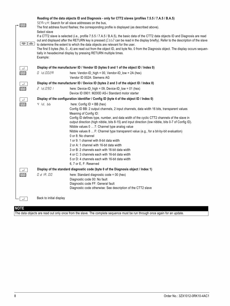
7 Order numbersScope of delivery
Accessories (must be ordered separately)
Other accessoriesAvailable fromGMC-I Messtechnik GmbHwww.gossenmetrawatt.com
Description Order number
AS-Interface addressing unit (in accordance with AS-i Specification V3.0), including 4 type AA batteries (IEC LR6, NEDA15),including addressing cable, with M12 plug to addressing plug (hollow plug), length approx. 1.5 m
3RK1904-2AB02
Description Order number
Connecting cable M12 connector to M12 socket, 3 x 0.34 mm², length 1.5 m 3RK1902-4PB15-3AA0
AS-Interface M12 feeder, transition AS-i flat cable to M12 socket 3RX9801-0AA00
AS-Interface M12 feeder, transition AS-i flat cable to M12 socket 3RK1901-1NR10
M12 cable connector, angled, cable outlet 90°, 5 x 0.34 mm², length 5 m, other cable end open
Note: For connecting the addressing unit to an AS-i network via AS-Interface M12 feeder, a connecting cable (M12 connector to M12 connector) with the following wiring must be fabricated:- M12 cable connector: Pin 1 / brown core ↔ M12 connector: Pin 1- M12 cable connector: Pin 3 / blue core ↔ M12 connector: Pin 3Pin 2, 4, 5 are not connected
3RK1902-4HB50-5AA0
M12 connector, straight, for screw fixing, 5-pole screw terminal, max. 0.75 mm² 3RK1902-4BA00-5AA0
AS-i coupling module FK/ADDRESS, with integrated addressing socket, for 2 AS-i cables (yellow), connection designed using EMS (electromagnetic interface) insulation displacement method, for addressing of older AS-i modules without addressing socket, user module type
3RK1901-1MA00
Description Order number
Addressing cable M12 connector to addressing plug (hollow plug), length approx. 1.5 m (included in the scope of supply of addressing unit as spare part)
Z236A

20 Order No.: 3ZX1012-0RK10-4AC1
AppendixDeutsch English Français
ACHTUNG NOTICE IMPORTANT
Wenn auf der Anzeige das Batterie-Zeichen „ “ erscheint, ist der Einbau von neuen Batterien erforderlich. Trennen Sie das Gerät vom AS-i Bus, bevor Sie es öffnen. Bei einem Batteriewechsel gehen die im Adressiergerät gespeicherten Konfigurationsdaten verloren.
If the battery sign " " appears in the display, new batteries must be installed. Disconnect the unit from the AS-i bus before you open it. When the battery is changed the configuration data stored in the addres-sing unit are lost.
Lorsque le symbole pile „ “ apparaît sur l'affichage, remplacer les piles. Déconnecter l'appareil du bus AS-i avent de l'ouvrir. Lors du changement des piles, la configuration se trouvant dans la console d'adres-sage est perdue.
Español Italiano Português
ATENCIÓN ATTENZIONE ATENÇÃO
Si aparece el pantalla el símbolo de batería " ", es necesario colocar baterías nuevas. Antes de abrir el equipo es necesario desconectarlo del bus AS-i. Si se cambian las baterías se pierden los datos de con-figuración almacenados en el equipo direccionador.
Se sul display appare il simbolo della batteria " ", si devono inserire delle batterie nuove. Prima di aprire il dispositivo, scollegarlo dal bus AS-i. Durante la sostituzione delle batterie i dati di configurazione memorizzati nel dispositivo di indirizzamento andranno persi.
Quando o sinal " " aparecer na indicação de bate-ria, é necessária a montagem de novas baterias. Separe o aparelho do canal AS-i, antes de abri-lo. Durante a troca de bateria, os dados de configuração armazenados no dispositivo de endereçamento são perdidos.
Türkçe Русский 中文
DİKKAT ВНИМАНИЕ 注意
Eğer ekranda „ “ pil sembolü görünürse, yeni pille-rin takılması gereklidir. Cihazı açmadan önce AS-i veri yolundan ayırın. Pil değiştirildiğinde adresleme cihazında kayıtlı konfigürasyon dosyaları silinir.
При появлении на индикаторе знака батареи „ “ следует вставить новые батареи. Перед тем как отрыть устройство, его следует отсоединить от шины AS-i. При замене батареи данные конфигу-рации, сохраненные в устройстве адресации, утрачиваются.
如果在显示器上出现了电池符号 “ ”,则说明需要安装新电池。在您将其打开之前,请将设备从 AS-i 总线断开。更换电池可能会导致寻址设备中存储的配置数据丢失。
DE Adressierung AS-i Slave ES Direccionado de esclavos AS-i TR AS-i Slave adresleme
EN Addressing of AS-i slav IT Indirizzamento dello slave AS-i РУ Адресация AS-i Slave
FR Adressage esclave AS-i PT Endereçamento AS-i Slave 中文 AS-i 从站定址
AS-i Slave
AS-i Module K20
3RK1902-4PB15-3AA0
3RK1901-1MA00
1 3 (4)
ASI+ ASI-
1 3 (4)
ASI+ ASI-
AS-i Motorstarter M200D
3RG9001
Pin 1 ASI+Pin 3 ASI-Pin 2, 4, 5: not connected
1
3
42
M12
(2)
(2)
1
AS-i Slave
etc.
Z236Awww.gossenmetrawatt.com

Technische Änderungen vorbehalten. Zum späteren Gebrauch aufbewahren.Subject to change without prior notice. Store for use at a later date.
Bestell-Nr. / Order No.: 3ZX1012-0RK10-4AC1© Siemens AG 2011
Technical Assistance: Telephone: +49 (0) 911-895-5900 (8°° - 17°° CET) SIEMENS AG
Fax: +49 (0) 911-895-5907 Technical Assistance
E-mail: [email protected] Würzburger Str. 121
Internet: www.siemens.com/industrial-controls/technical-assistance D-90766 Fürth
DE Anschluss AS-i System ES Conexión del sistema AS-i TR AS-i sistemi bağlantısı
EN Connection of AS-i system IT Collegamento del sistema AS-i РУ Подключение системы AS-i
FR Raccordement du système AS-i PT Ligação do sistema AS-i 中文 连接 AS-i 系统
Deutsch English Français
ACHTUNG NOTICE IMPORTANT
Für den Anschluss eines AS-i Systems muss das AS-i Netz durch ein AS-i Netzteil oder über eine AS-i Datenentkopplung versorgt werden.
For the connection of an AS-i system, the AS-i network must be supplied by an AS-i power supply unit or via an AS-i data decoupling.
Le raccordement d'un système AS-i nécessite une ali-mentaiton fournie par un module d'alimentation AS-i ou par un couplage de données AS-i.
Español Italiano Português
ATENCIÓN ATTENZIONE ATENÇÃO
Para conectar un sistema AS-i, la red AS-i debe ser ali-mentada por una fuente AS-i o a través de un módulo de desacoplamiento de datos AS-i.
Per il collegamento di un sistema AS-i si deve alimentare la rete AS-i con un alimentatore da rete AS-i o con un modulo di disaccoppiamento dati AS-i.
Para a ligação de um sistema AS-i, a rede AS-i precisa ser abastecida através de uma fonte de alimentação AS-i ou pelo desacoplamento de dados AS-i.
Türkçe Русский 中文
DİKKAT ВНИМАНИЕ 注意
Bir AS-i sisteminin bağlanması için AS-i şebekesinin bir AS-i güç adaptörü veya AS-i veri dekuplaj sistemi üzerin-den beslenmesi şarttır.
Для подключения системы AS-i необходимо запитать сеть AS-i от блока питания AS-i или через развязку передающихся данных AS-i .
AS-i 网络必须通过 AS-i 电源模块或 AS-i 数据去耦连接到 AS-i 系统。
2
!
AS-Interface
AS-Interface
Slave 1
OFF !
3RX9801-0AA0
1 3
ASI+ ASI-
ASI+ASI-
1 3
3RK1901-1NR10
Slave 2
3RX950
AS-i Master
AS-i Netzteil
Montage / Installation / Montage / Montaje / Montaggio / Montagem / Montaj / Монтаж / 安装
3RK1902-4BA00-5AA0 3RK1902-4HB50-5AA0
ASI+ Pin 1
braun / brown / brun / marrón/ marrone / mar-rom / kahverengi / коричневый / 安装
ASI- Pin 3blau / blue / bleu / azul/ blu / azul / mavi / синий / 蓝色
Pin 2, 4, 5: not connected
3RK1902-4HB50-5AA0 +3RK1902-4BA00-5AA0


![UNIT t Logical Addressing[RGPV/Jun 2014]](https://static.fdocuments.in/doc/165x107/61ed062e7a02dc668f5863a8/unit-t-logical-addressingrgpvjun-2014.jpg)