As Global Mapper opens click on button “Open Your Own...
28
1 ====================================== ASTRA Pro Release 6.0, User’s Guide for Tutorial Data Tutorial 11 User's Guide for Stream Hydrology ====================================== In this session we shall see to compute the volume of Water Stored at a Dam Site, The Ground Elevation data is taken by downloading fro Shuttle Radar Topography Mission (SRTM) using Broad band Internet and is saved as file SURVEY.TXT, User has to install Licensed Version of software Global Mapper for this data processing. User may visit web site www.globalmapper.com for details, Select ASTRA Pro main screen menu option “Programs>>Global Mapper V11>>Run Program”, As Global Mapper opens click on button “Open Your Own Data Files”,
Transcript of As Global Mapper opens click on button “Open Your Own...

1
======================================
ASTRA Pro Release 6.0, User’s Guide for Tutorial Data
Tutorial 11 User's Guide for Stream Hydrology
======================================
In this session we shall see to compute the volume of Water Stored at a Dam Site, The Ground
Elevation data is taken by downloading fro Shuttle Radar Topography Mission (SRTM) using Broad
band Internet and is saved as file SURVEY.TXT, User has to install Licensed Version of software Global
Mapper for this data processing. User may visit web site www.globalmapper.com for details,
Select ASTRA Pro main screen menu option “Programs>>Global Mapper V11>>Run Program”,
As Global Mapper opens click on button “Open Your Own Data Files”,

2
Select file “Terrain [UTM+44N+WGS84].dwg” from the working folder “Tutorial 14 User's Guide for
Project Stream Hydrology\Project Data”, Click on button “Open”,
Next the Dialog box comes for Setting Projection as UTM, Zone as 43 Northern Hemisphere, Datum as
WGS84, Planar Units as METERS, Elevation Units as METERS, Click on button “OK”,

3
The Drawing is opened in Global Mapper,
User must ensure that Broad bad Inter connection is available in the system and Firewall of installed
Antivirus program is turned “OFF”, Click left mouse button on item “SRTM Worldwide….” In the list as
shown below, Click on button “OK”,

4
The Terrain Data is retrieve from SRTM and the Global Mapper screen comes as shown below,

5
Select Global Mapper main screen menu item “Export Raster and Elevation Data>>Export xyz Grid”,

6
The Message box comes as shown below, Click on button “OK”,
The Dialog box comes to select “XYZ Grid Export Options”, Select “Space”, Click on button “OK”,

7
To save the Ground Elevation data type the File name “Terrain_SRTM”, Save as type “XYZ Grid Files”,
Click on button “Save”,
The file “Terrain_SRTM.xyz” is saved in the working folder as shown below,

8
Change the file extension from Terrain_SRTM.xyz to Terrain_SRTM.txt,
The message comes as shown below, Click on button “Yes”,
The file Terrain_SRTM.txt is opened with Notepad for viewing, After viewing close the Notepad,

9
The file “Terrain_SRTM.txt” is opened in MS Excel,
The Column A for Serial number and Column E for Feature code and is saved as SURVEY.TXT as
shown below,
10
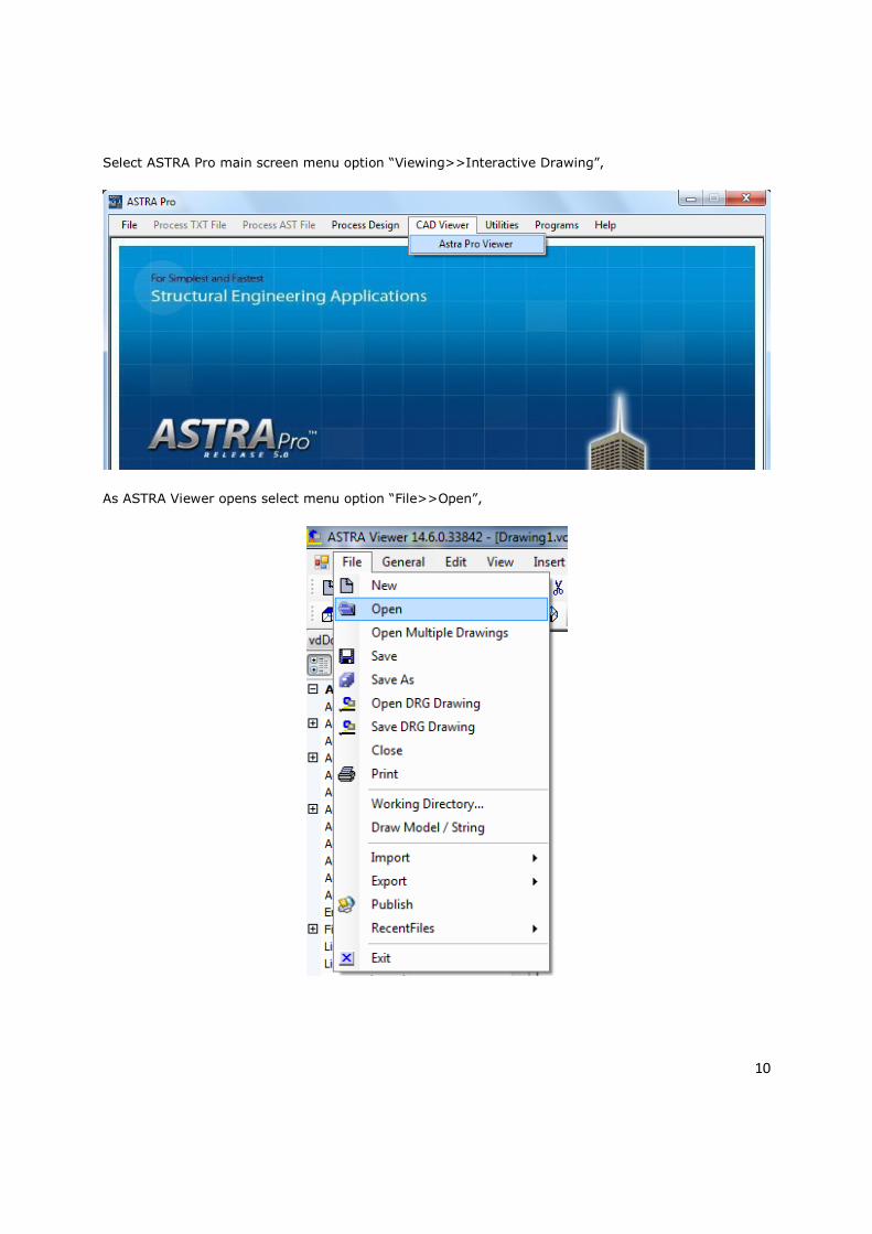
Select ASTRA Pro main screen menu option “Viewing>>Interactive Drawing”,
As ASTRA Viewer opens select menu option “File>>Open”,

11
Select file “Boundary String.dwg” created already plotting the River Center Line and a Boundary Line
around the River Center Line, by clicking on it and Click on button “Open”,
The drawing is opened, The Boundary line in Black color is for processing Ground elevation data only
within it, The String for River Center Line is in Blue color, Click on it, as selected blue boxes come on
it, Select Astra Viewer menu option “DesignUtils>>Make String” as shown below,

12
As the Dialog box comes type Model Name “DESIGN” and String label “M001”, Click on button “OK”,
This will write String M001 for River Center Line in the model files and Master String Data will be
written in file HALIGN.FIL and this will be used to display Chainage later on,
The Boundary String is in White color, Click on it, as selected blue boxes come on it, Select Astra
Viewer menu option “DesignUtils>>Boundary String” as shown below,
As the Dialog box comes type Model Name “BOUND” and String label “BDRY”, Click on button “OK”,
This will write String “BDRY” under Model “BOUND” for Boundary Line in the model files,

13
Select Astra Viewer menu option “DesignUtils>>Modeling from text Data”,
Select file “SURVEY.TXT” from working folder by clicking on it, Click on button “Open” as shown below,

14
The modeling is done and the Message Box comes, Click on button “OK”,
Next, Select Astra Viewer menu option “DesignUtils>>Ground Modeling”,

15
As the Dialog box comes, The model name “SURVEY” and string “OGL” is already selected, Click on
button “OK”,
To start the process of Triangulation click on button “PROCEED”,

16
As the process finishes the message comes as shown below, The DTM file as the output of Triangulation
are written as HDS001.FIL, HDS000.FIL, Contour.FIL in the working folder, Click on button “OK”,
Next process is for creating Contours by reading the DTM files, Select Astra Viewer menu option
“DesignUtils>>Ground Modeling”,

17
To start click on button “RUN”,
As the Contour development process finishes click on button “Save” as shown below, Maximize
RUN/QUIT from the bottom Panel as shown below, by clicking on Icon and Quit,
Next, Click on “QUIT” to finish the process of creating Contours, the Contours are saved in the model
files MODEL.FIL & MODEL.LST,

18
Select Astra Viewer menu option "Format>>Layers Dialog" ,
In Layer Dialog box type Layer name M001, Click on “New layer”, Click on Color box, Take a color,
In Layer Dialog box type Layer name CHAINAGE, Click on “New layer”, Click on Color box, Take a
color, In Layer Dialog box type Layer name C005, Click on “New layer”, Click on Color box, Take a
color, Click on Layer “C005” & button “Set Current”, Layer “C005" will be Current Layer, Click on
button “OK”,

19
Select Astra Viewer menu option “File>>Draw Model / String”,
Select Model Name “CONTOUR”, String Label “C005” & “ELEV”, Click on button “OK” as shown below,

20
Click on Layer “M001” & button “Set Current”, Layer “M001” will be Current Layer, Click on button
“OK”,
Select Astra Viewer menu option “File>>Draw String”,

21
Select Model Name “DESIGN”, String Label “M001”, Click on button “OK” as shown below,
Click on Layer “CHAINAGE” & button “Set Current”, Layer “CHAINAGE” will be Current Layer, Click on
button “OK”,
22
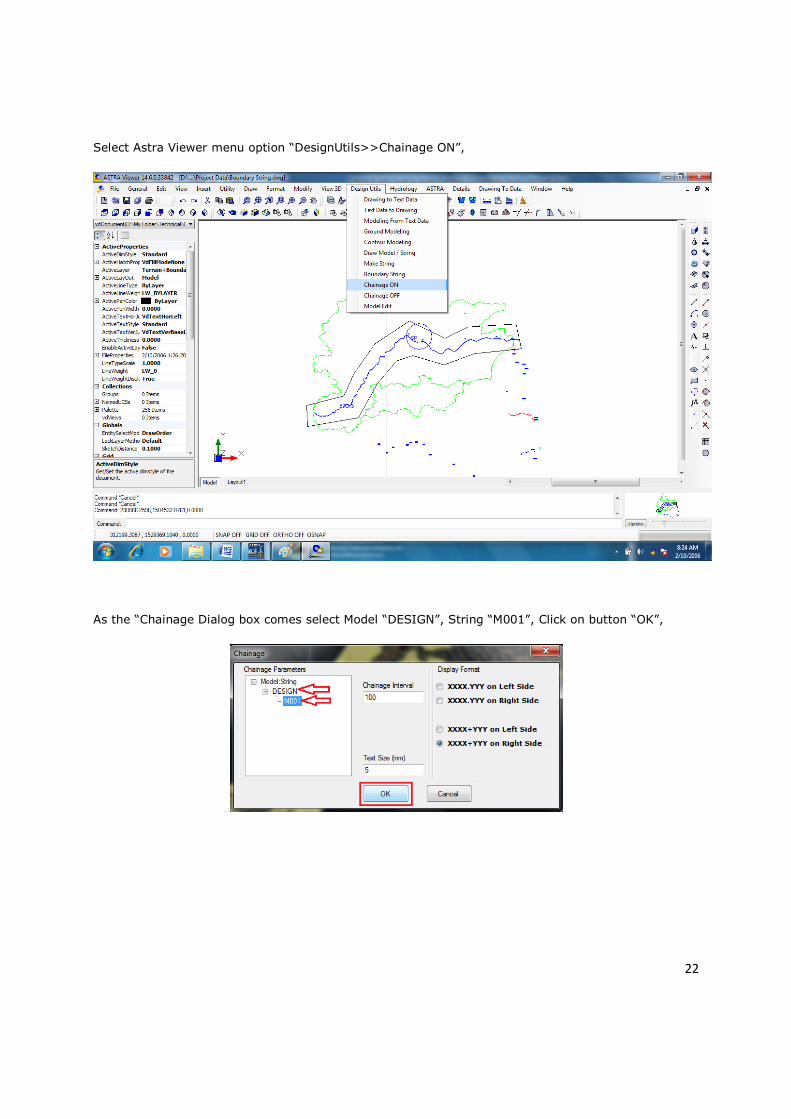
Select Astra Viewer menu option “DesignUtils>>Chainage ON”,
As the “Chainage Dialog box comes select Model “DESIGN”, String “M001”, Click on button “OK”,

23
Select Astra Viewer menu option “File>>Save as” as shown below,
As the save Dialog box comes type File Name “CONTOUR”, Save as type “DWG 2004”, Click on button
“Save”, The drawing is saved as ‘CONTOUR.dwg” in the working folder,

24
The drawing contains Strings “C005” for Contours with Elevations, String “M001” for River Center Line
with Chainages, A Bridge may be Located at Chainage “0.0”, from this point Chainage is increasing
towards the Upstream of the River,
The River Center Line at its various Chainages intersects Contours of different elevations, At Chainage
3+300 Km River Center Line intersects Contour with elevation 120.0 metres, At Chainage 10+130 Km
River Center Line intersects Contour with elevation 140.0 metres and so on,

25
Select Astra Viewer menu option “Hydrology>>Stream Hydrology>>New Calculation for Hydrograph”,
The working folder is selected as “01 ASTRA Pro Tutorials>>Tutorial 10 Stream Hydrology &
Hydrograph>> Project Data”, Click on button “OK”,

26
The Calculation Worksheet for Hydrological calculation and Hydrograph is opened in MS Excel as
shown below, The Various Chainages of the River Centre Line and the elevations of intersecting
Contours are entered in two relevant columns, Other values are computed based on the formulae
embedded in the Worksheet,

27
For a length of 59.0 Km of center Line, an area of 1000 Sq. Km is considered in the problem, For a
period from 0 Hours to 23 Hours, at 6.2 Hours the Discharge of 363.0 Cumecs is found as maximum,
at 0 Hours and at 23 Hours the Discharges are 0.0 Cumecs, at 3 Hours the Discharges is 100 Cumecs,
These are base points to draw the Hydrograph, Other points are decided to get a smooth curve as
shown below,

28
Various calculations are done by writing formulas following the relevant sections of the Country’s
Standard and finally the conclusion is made whether the Waterway at Bridge location is Adequate or
Inadequate,
TECHSOFT ENGINEERING SERVICES
179, BANGUR AVENUE, BLOCK - A,
KOLKATA - 700 055
TEL: 033 - 4008 3349, 6526 149,
EMAIL: [email protected], [email protected]
WEB SITE: www.headsview.com