as at 1 October 2014 - Indeco · Types of INDECO Door Systems Bottom Roller Sliding Doors -...
100
PN-EN 1527:2000 ITB AT-15-7902/2009 INDECO TECHNICAL CATALOGUE 2014 as at 1 October 2014
Transcript of as at 1 October 2014 - Indeco · Types of INDECO Door Systems Bottom Roller Sliding Doors -...

PN-EN 1527:2000 ITB AT-15-7902/2009
INDECO TECHNICAL CATALOGUE 2014
as at 1 October 2014

www.indeco.eu

www.indeco.eu
S100 - SERIES SLIDING DOORS (steel system))..................................................................................................................................3
S200 - SERIES SLIDING DOORS (steel system)................................................................................................................................14
S300 - SERIES PIVOTED DOORS (steel system)...............................................................................................................................19
A100 - SERIES SLIDING DOORS (aluminium system)....................................................................................................................24
ONTARIO - FRAMELESS DOORS (aluminium system)...................................................................................................................42
ATHABASCA - NARROW FRAME DOOR (aluminium system).......................................................................................................48
A200 - SERIES SLIDING DOORS (aluminium system)....................................................................................................................54
A500 - SERIES SLIDING DOORS (aluminium system).....................................................................................................................62
A600 - SERIES PIVOTED DOORS (aluminium system)....................................................................................................................72
A800 - SERIES FOLDING DOORS (aluminium system)..................................................................................................................79
INDECO TOOLS AND ACCESSORIES..................................................................................................................................................86
INDECO PROFILES...............................................................................................................................................................................90
Aluminium Profile Colour Range......................................................................................................................................................91
Steel Profile Colour Range.................................................................................................................................................................93
Sales Support Tools.............................................................................................................................................................................94
Orders....................................................................................................................................................................................................96
Contents
1

www.indeco.eu
Types of INDECO Door Systems
Bottom Roller Sliding Doors- Convenient access to the closet/wardrobe- A wide range of designs- Any front width, any number of door leaves- All leaves can be slid to one side in a multiple-track system
Bottom Roller Slant Sliding Doors- Full use of space in rooms with lowered, slant ceilings (attics, lofts)- Doors fitted to slant walls
Top Roller Sliding Doors- Suspended doors without the bottom track- Can also be used as pocket doors- Any front width, any number of door leaves- Excellent both for very wide and for very narrow doors- Can be easily trimmed at the bottom
Top and Bottom Roller Sliding Doors- The highest strength and durability- The door can be trimmed at the bottom- The door can be out-of-plumb- Special decorative effects can be obtained, such as inclined doors
Walk-through Sliding Doors without Thresholds- Full access to a walk-in closet- Can be used as pocket doors- No threshold
Pivoted Doors- Single and double, left-hand and right-hand doors- Access to the entire wardrobe content- A good solution for narrow doors
Folding Doors without Thresholds- Full access to the entire wardrobe content- Large wardrobe widths possible- Need half the space to open compared to pivoted doors with the same wardrobe width- No threshold
2

www.indeco.eu
bottom roller sliding doors
INDECO S100 SERIES STEEL SYSTEM
Boundary conditions:
- maximum dimensions of the opening: 2800 mm in height; any width with sections of up to 5000 mm each.
- maximum dimensions of individual doors: 2750 mm in height, 1300 mm in width or, for light doors not exceeding 50 kg, the door width can be increased to 2000 mm.
- maximum weight of 50 kg.
- panel thickness of 4 mm and 10 mm.

4
Assembly drawing123456789
051041052551xx060015xx060020xx0700yyxx0800yyxx0850yyxx099250099259PLS
Bottom RollerTwin Wheel Top GuideSteel Double Bottom TrackSteel Double Top TrackSteel Rail
Steel Stile Steel Stile
1011121314151617181920
811000xx82100003093000xx099260099263092000xx880000xx099249099249A
Dust Stop Brush StripBottom Roller Guard left/rightSteel Connector Rail10/4/25 Spacer10/4/10 SpacerStick-on Decorative Strip Safety BackingBuffer Strip ClipBuffer Strip Clip
19 810000xx Buffer Strip20
21
09924509923X
Steel System Soft Closer AccessoriesUniversal Soft Closer
INDECO S100 SERIES STEEL SYSTEMbottom roller sliding doors Components
Top PositionerPositioner, grey plastic
7
2
2020
20
21
4
8
9
5
6
1
10
13
12
3
18
14
1619
11
17
15
n=4 z=3
n=4 z=2
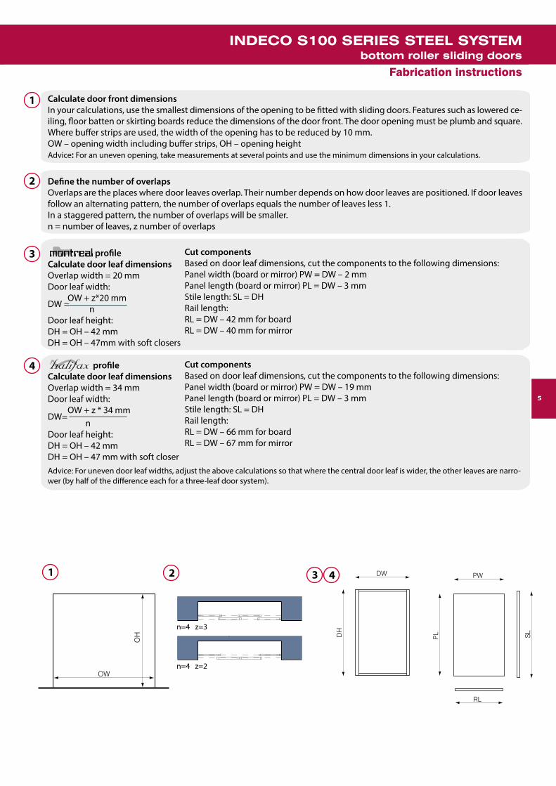
profileCalculate door leaf dimensionsOverlap width = 20 mmDoor leaf width: OW + z*20 mm nDoor leaf height: DH = OH – 42 mmDH = OH – 47mm with soft closers
profileCalculate door leaf dimensionsOverlap width = 34 mmDoor leaf width: OW + z * 34 mmDW= nDoor leaf height: DH = OH – 42 mmDH = OH – 47 mm with soft closer
1
2
2 3 41
3
4
Calculate door front dimensionsIn your calculations, use the smallest dimensions of the opening to be fitted with sliding doors. Features such as lowered ce-iling, floor batten or skirting boards reduce the dimensions of the door front. The door opening must be plumb and square. Where buffer strips are used, the width of the opening has to be reduced by 10 mm.OW – opening width including buffer strips, OH – opening heightAdvice: For an uneven opening, take measurements at several points and use the minimum dimensions in your calculations.
Define the number of overlapsOverlaps are the places where door leaves overlap. Their number depends on how door leaves are positioned. If door leaves follow an alternating pattern, the number of overlaps equals the number of leaves less 1.In a staggered pattern, the number of overlaps will be smaller.n = number of leaves, z number of overlaps
Advice: For uneven door leaf widths, adjust the above calculations so that where the central door leaf is wider, the other leaves are narro-wer (by half of the difference each for a three-leaf door system).
Cut componentsBased on door leaf dimensions, cut the components to the following dimensions:Panel width (board or mirror) PW = DW – 2 mmPanel length (board or mirror) PL = DW – 3 mmStile length: SL = DHRail length:RL = DW – 42 mm for boardRL = DW – 40 mm for mirror
Cut componentsBased on door leaf dimensions, cut the components to the following dimensions:Panel width (board or mirror) PW = DW – 19 mmPanel length (board or mirror) PL = DW – 3 mmStile length: SL = DHRail length:RL = DW – 66 mm for boardRL = DW – 67 mm for mirror
5
INDECO S100 SERIES STEEL SYSTEMbottom roller sliding doors
Fabrication instructions
OW
OH
DW
RL
DH
PW
PL SL
DW =

6
1,5
Install railsBefore assembly, cut installation holes at both ends of the rails using the universal notching tool 89000003.Put one end of the rail against the stile. Using a rubber mallet, tap the rail in place along the entire length. Fix the other rail likewise.Advice:Owing to panel (mirror, glass or laminated board) cutting tolerances, panel dimensions may differ slightly from the desired ones. To avoid pro-blems, before cutting the rails, measure the distance between the stiles and cut the rails to that length. Take care not to cause the stile ends to flare out when tapping the rail into place.
5 67
8
8
9
9
4 10
Tap stiles and spacers onto panelsTap stiles and spacers onto panels as per the drawings. To set glass panels in 10 mm profiles use the spacer 099260.
Mirror protectionUse colour and/or clear safety (laminated) glass. When using a mirror, fix safety backing 88000011or 88000012 to the back of the mirror, so that the backing strips overlap. Having fixed the backing, expel air bubbles using a brush or roller.Advice: For full safety make sure that mirror edges are ground smooth with abrasive paper in order to reduce internal stress.
Combination panelsWhen making a combination panel, connect it by means of a connector before you assemble the stiles (vertical profiles). To install glazed panels, tap the spacer 099263 onto the panel. To combine a glass panel with a board, set the glass panel in the stile by tapping the spacer 099260 onto it.
Install stilesBefore assembly, cut installation openings at both ends of the stiles using the notching tool 89000003 or the automatic notching tool 89000009.Put one end of the stile against the corresponding end of the panel and tap the stile in place using a rubber mallet along the entire length, so that it protrudes 1.5 mm at both ends of the panel. Fix the other stile likewise.Advice: For a mirror, exercise special care when you start fixing the stile. Tap the stile carefully in position on the panel. Do not remove the protec-tive backing from the stile when fitting the door at the customer’s place.
5
6
7
INDECO S100 SERIES STEEL SYSTEMbottom roller sliding doors Fabrication instructions

7
11
10
10
12
12
11
fixing screws
www.indeco.eu
INDECO S100 SERIES STEEL SYSTEMbottom roller sliding doors
Fabrication instructions
NoteFix buffer strips and dust-stop brush strips only after door installation has been completed. The entire glass surface (mirror, stained glass) should be secured with safety backing in compliance with the applicable laws and regulations. Only laminated safety glass can be used for clear-glass panelling. In order to reduce the risk of glass cracking as a result of stress produced during cutting, make sure that glass edges are ground smooth with abrasive paper or stone.
Fix bottom rollers and top guidesSlip guide tongues into the openings in the rail and then, turning the roller gently, push it so the catch snaps into the notch in the stile. Fix the other guides in the same manner.
Advice: To protect the anti-jump feature against damage or breaking, the bottom roller wheel should be fully recessed into the roller body during transport.
Structural reinforcementIn order to reinforce the door leaf structure, you can optionally fix the rollers and guides to the profiles using 3.5 x 9.5 sel-f-tapping screws 87000050. Use two screws to fix the roller to the stile, driving them through the holes in the eyes abut-ting the stile. Then fix the tongue abutting the rail, driving one screw through one of the two holes. Fix the other rollers in the same manner.
Advice: When fixing the rollers to the rails on glazed doors, exercise special care to avoid glass damage within the rail. Always use a power screwdriver to fix self-tapping screws.
Installation of the soft closer with a 4 mm rail1. Before fixing the rail, put one adapter against the rail, mark the positions of rivet holes, and then drill 3.5 mm rivet holes.2. Rivet one adapter to the rail.3. Then mount the soft closer onto the adapter, put the other adapter in place, mark the positions of rivet holes, and then drill 3.5 mm rivet holes.4. Rivet the other adapter.5. Fasten the soft closer to the adapters with screws.6. Mount the rail with soft closer to the door leaf.7. Measure the distance between the door edge and the adapter (“X”).

www.indeco.eu
8
13
14
X+A Domykacz lewy tor wewnętrznyX+A Domykacz prawy tor wewnętrzny
X+A Domykacz lewy tor zewnętrznyX+A Domykacz prawy tor zewnętrzny
AktywatorAktywator
Dla domykacza prawego w torze zewnętrznym wymiar "A" = 55mm.Dla domykacza prawego w torze wewnętrznym wymiar "A" = 93mm.Dla domykacza lewego w torze zewnętrznym wymiar "A" = 93mm.Dla domykacza lewego w torze wewnętrznym wymiar "A" = 55mm.
Montaż aktywatora domykacza.Zamontuj aktywator w odległości "X" + "A" od krawędzi toru.
fixing screws
Installation of the soft closer with a 10mm rail1. Having fixed the rail, put one adapter against the rail and mark the position of the mounting screw hole.2. Drill a 3.5mm hole in the rail for the mounting screw and mount the adapter onto the rail.3. Then mount the soft closer onto the adapter, put the other adapter in place and mark its position.4. Remove the soft closer, put the adapter in the marked place and set the position of the mounting screw hole.5. Drill a 3.5mm hole in the rail for the mounting screw and mount the adapter onto the rail.6. Fasten the soft closer to the adapters with screws.7. Measure the distance between the door edge and the adapter (“X”).
13
Installation of the soft closer trigger. Mount the trigger at the distance “X” + “A” from the track edge
For the right-hand soft closer in the outer track, dimension “A” = 55mm.For the right-hand soft closer in the inner track, dimension “A” = 80mm.For the left-hand soft closer in the outer track, dimension “A” = 80mm.For the left-hand soft closer in the inner track, dimension “A” = 55mm.Before fixing the screws, drill lead holes in the top track with a 2mm drill bit.
14
INDECO S100 SERIES STEEL SYSTEMbottom roller sliding doors Fabrication instructions
X+A Right-hand soft closer inner track
X+A Left-hand soft closer inner track
X+A Right-hand soft closer outer track
X+ALeft-hand soft closer outer track
Trigger

www.indeco.eu
9
5~27
1 2 3 4
Cut the tracksCarefully measure the width of the opening at top and bottom, and reduce the lengths measured by about 2-3 mm. Measure off the required track length, marking the future cut line on the tracks. Use a fine-toothed metal cutting saw to cut off the redundant part of the tracks.
Advice:The tracks to be installed should be about 50 mm longer than the opening width. This spare length will make it possible to avoid measurement errors and it is easy to trim. Take care not to damage the track surface while cutting. In order to facilitate top track cutting, insert 38 mm thick wood blocks or a reversed piece of track into the track. This will prevent track deflection during the cutting process.
Install the top trackFix the top track with screws, offsetting its flat surface by 5 mm from the door face (inwards). Install the top track with the shade line facing forward in order to mask ceiling irregularities. If a multiple-track system is installed, fix the other tracks so that they fit tightly against each other along the entire length.
Advice: Before you start installation use a detector to make sure there is no electrical wiring at the screw fixing points. Avoid applying excessive force when tightening screws to prevent track deformation. Use flat-head screws for best results. The surface to which the track is fixed must not be curved.
Install the doorLay the bottom track on the floor, offsetting it about 27 mm from the door face (inwards). Use a Philips screwdriver and the adjusting bolt to move bottom rollers out about 10 mm. Fully insert the door leaf in the top track, taking care not to damage the bottom rollers, then align the bottom end of the door leaf with the bottom track and slowly lower the leaf, letting the rollers snap into the track guides.
Advice: Before you install the doors, put a cardboard sheet on the bottom track to prevent damage to track surface. When the doors are already in position, remove the protective cardboard.
Install the bottom trackUse a level to make sure the door is exactly plumb; move the bottom track as necessary. Check if the door travels smoothly along the entire width of the opening. Having precisely set the bottom track, fasten it to the floor. Having installed the track, put the other door leaves in their respective tracks.
Advice: Before you fix the bottom track, make sure that it is positioned exactly parallel to the top track. With soft floor covering, before you fix the bottom track, cut out a strip of about 55 mm in width and replace it with a 55 mm timber batten. Alternatively, put a 100 mm floor batten between the floor covering and the bottom track. Avoid applying excessive force when tightening screws to prevent track deformation. Use flat--head screws for best results.
1
2
3
4
INDECO S100 SERIES STEEL SYSTEMbottom roller sliding doors
Installation instructions

www.indeco.eu
10
x
buffer strip
dust stop brush
5 6 7
8
Fix the top positionersFix the positioner 099265 to the top track so that it fits against the middle part of the track at an appropriate distance from the wall. Cut the positioner 099259PLS to the right size and fix in the middle of the top track so that the door abuts on the side wall of the unit when closed.
For the profile x = 32 mm, where no buffer strip is used,x = 37 mm, where a buffer strip is used.
Adjust door positionAdjust door position by means of a Philips screwdriver and the adjusting bolts in the bottom rollers so that the doors fit tightly against the wall along the entire length. Door-to-floor clearance is adjustable between 10 and 40 mm (2 to 32 mm from the bottom track).
Fix the buffer and dust-stop brush stripsHaving installed the doors, remove protective backing from the door profiles. With the backing removed, you can fix the buffer strips and the dust-stop brush strips. To ensure good adhesion of the brush strips to the profiles, gently clean the profiles with alcohol or white spirit. Fix the strips, working from top to bottom. Cut off excess strip.
Fix the buffer strip clipTo fix the clip 099249 or 099249A, the door must first be installed and adjusted. After that operation, fix the buffer strip and then mount the clip. For easier and correct installation, we recommend that the door should be taken off the tracks.
Advice: For details of the buffer strip clip installation see separate instructions, “Technical information– fixing the buffer strip clip” available on our website in the section designated for Authorised Partners.
5
6
7
8
INDECO S100 SERIES STEEL SYSTEMbottom roller sliding doors Installation instructions
For the profilex = 44 mm, where no buffer strip is used,x = 49 mm, where a buffer strip is used.

11
INDECO S100 SERIES STEEL SYSTEMbottom roller sliding doors
System components
051041
Bottom Roller for Steel System.Body made from galvanized structural steel, designed forsnap and screw fixing. The moving part is adjustable withinthe 0-32 mm range by means of an adjusting bolt and isprovided with an anti-jump feature. The roller has a wheelof a high-strength plastic with an embedded sealed ballbearing. Resistance: up to 60 kg/2 rollers, up to 50,000 open/close cycles. Packaging: 100 pcs/pack. Weight: ~11.87 kg/pack. Availability: continuous.
1 052551xx
Twin Wheel Top Guide.Body made from galvanized structural steel, designed forsnap and screw fixing. The guide features wheels of high--strength plastic and vibration damping rubber. The mo-ving part allows the wheels to be adjusted within the 0, 16, 32 mm range. The wheels, fixed to an elastic moving arm, precisely follow the track. The guides are available in two versions:- with INDECO logo – 052551LL,- without INDECO logo – 052551LO.Packaging: 100 pcs/pack. Weight: ~5.10 kg/pack.Availability: continuous.
2
40,8
63,8
8
3 060020xx
Steel Double Top Track, 5 m.Track made from galvanized zinc-coated steel sheet, fi-nished with polyester paint or simulated wood film.Material thickness: 0.5 mm. Colours: xx: SSR, SSA, SGL, SWP, SBP, SVP, SBT, SET, SOT, SLT, SCT, SPT, SWT, SMT, SNT. Packaging: 4 pcs/pack. Weight: ~20.4 kg/pack.Availability: continuous.
84
44
38,6
4
0700yyxx
Steel Rail, 2.4 m.A rail for 4 or 10 mm mirror panels to steel door systems.Made from galvanized zinc-coated steel sheet, finished withpolyester paint or simulated wood film. Material thickness:0.5 mm. Versions: yy: 03 – 4 mm, 10 – 10 mmColours: xx: SSR, SSA, SGL, SWP, SBP, SVP, SBT, SET, SOT, SLT, SCT, SPT, SWT, SMT, SNT. Packaging: 40 pcs/pack. Weight: ~22.80 kg/pack.Availability: continuous.
16
16
5
Ø3.2
92
67.5
Ø35
16.9Ø17.8
76.7 Ø3.2
40.5
18
11
6 0800yyxx
Steel Stile, 2.75 m.A stile for 4 or 10 mm mirror panels to steel door systems.Made from galvanized zinc-coated steel sheet, finishedwith polyester paint or simulated wood film. Versions: yy: 03 – 4 mm, 10 – 10 mm. Colours: xx: SSR, SSA, SGL, SWP, SBP, SVP, SBT, SET, SOT, SLT, SCT, SPT, SWT, SMT, SNT. Packaging: 20 pcs. Weight: ~20.00 kg/pack.Availability: continuous.
20,5
29,2
40.838.6
20.5
29.2
63.8
060015xx
Steel Double Bottom Track, 5 m.Track made from galvanized zinc-coated steel sheet, fi-nished with polyester paint or simulated wood film. Materialthickness: 0.5 mm. Track length: 5000 mm.Colours: xx: SSR, SSA, SGL, SWP, SBP, SVP, SBT, SET, SOT, SLT, SCT, SPT, SWT, SMT, SNT. Packaging: 10 pcs/pack. Weight: ~20.4 kg/pack.Availability: continuous.

12
099259PLS
Positioner, grey plastic.Sets the S100 system door leaf in the end position.It is stuck to the top track.Application: S100.Availability: continuous.
INDECO S100 SERIES STEEL SYSTEMbottom roller sliding doors System components
12
13
0850yyxx
. Steel Stile, 2,75 m.A stile for 4 or 10 mm mirror panels to steel door systems.Made from galvanized zinc-coated steel sheet,finished with polyester paint or simulated wood film.Versions: yy: 03 – 4 mm, 10 – 10 mmColours: xx: SSR, SSA, SGL, SGP, SWP, SBP, SVP, SBT, SET, SOT, SLT, SCT, SPT, SWT, SMT, SNT. Packaging: 15 pcs. Weight: ~19.50 kg/pack.Availability: continuous.
0800yyxx
Steel Stile, 2.75 m.A stile for 4 or 10 mm mirror panels to steel door systems.Made from galvanized zinc-coated steel sheet,finished with polyester paint or simulated wood film.Versions: yy: 03 – 4 mm, 10 – 10 mmColours: xx: SSR, SSA, SGL, SGP, SWP, SBP, SVP, SBT, SET, SOT, SLT, SCT, SPT, SWT, SMT, SNT. Packaging: 20 pcs/pack. Weight: ~20.00 kg/pack.Availability: continuous.
0850yyxx
Steel Stile, 2.75 m.A stile for 4 or 10 mm mirror panels to steel door systems.Made from galvanized zinc-coated steel sheet,finished with polyester paint or simulated wood film.Versions: yy: 03 – 4 mm, 10 – 10 mm. Colours: xx: SSR, SSA, SGL, SGP, SWP, SBP, SVP, SBT, SET, SOT, SLT, SCT, SPT, SWT, SMT, SNT. Packaging: 15 pcs/pack. Weight: ~19.50 kg/pack.Availability: continuous.
7
8
9
10
11
099250
Top Positioner.A component that holds in position steel system doors.Packaging: 50 pcs/pack. Weight: ~0.42 kg/pack.Availability: continuous.
126.7
82100003
Bottom Roller Guard left/rightA set of bottom roller guards (right and left) for steelsystems. Colour: grey. Packaging: 40 sets/pack.Weight: ~1.49 kg/pack. Availability: continuous.
8
6.7
811000xx
Self-adhesive Dust-stop Brush 6.7 x 12.A brush designed to seal the space between door leaves and to stop dust. Hair length: 12 mm. Colours: xx: 00 – white, 06 – black, 112 – brown, 13 – beige, 20 - grey.Packaging: 00, 06, 12, 13 - 300 m/roll 20 - 200 m/roll. Weight: 00, 06, 12, 13 - ~4.04 kg/roll. 20 -~2.56 kg/roll. Availability: continuous (white, beige, grey);to order (other colours).
811000xx
Self-adhesive Dust-stop Brush 6.7 x 8.A brush designed to seal the space between door leaves and to stop dust. Hair length: 8 mm. Colours: xx: 19 - grey.Packaging: 200 m/roll. Weight: ~21.14 kg/roll.Availability: continuous.
33.4
28.2
32
4 or
10
23,6
4 or
10

13
22
23
099245
Steel System Soft Closer Accessories.These items are used to fix the universal soft closer to a steel system door leaf. The steel system door closeraccessories include:- Trigger- Soft closer adapter, right- Soft closer adapter, left- Adjusting screw 2.9 x 19mm (1 pce)- Trigger mounting screws 3.5 x 16mm (2 pcs)- Soft closer adapter mounting screws 2.9 x 13mm (2 pcs)- Soft closer mounting screws M3 x 16 mm (4 pcs)- Soft closer adapter mounting rivets (4 pcs)Application: S100.Availability: continuous.
09923x
Universal Soft Closer.It ensures that the door leaf closes softly to its end position. The soft closer features an air damper, which gu-arantees durability and performance stability throughout its useful life. The design of the soft closer body allows it to be used as a left-hand or right-hand closer. The installation of the soft closer on the steel system-based door leaf is possible with the use of the steel system door closer accessories 099245.The soft closer is available in two versions:099233 – soft closer for doors of up to 25kg in weight.099234 – soft closer for doors of 25 to 50kg in weight.Application: S100, A100, A200.Availability: continuous.
21 810000xx
Self-adhesive Buffer Strip, 4.8x5 or 4.8 x 4.A strip designed to dampen door impact against the walland eliminate minor wall irregularities.Hair length: 5 mm or 4 mm. Colours: xx: 00 – white, 06 –black, 12 – brown, 13 – beige, 20 - greyPackaging: 450m/roll grey; 550 m/roll other colours. Weight: ~2.90 kg/roll. Availability: continuous (white, be-ige, grey); to order (other colours).
4-5
4.8
17
18
19
092000xx
Stick-on Decorative Strip. Length: 2.4 m.A decorative steel strip to be stuck on the steel system panel. Made from galvanized zinc-coated steelsheet, finished with polyester paint or simulated wood film. Colours: xx: SSR, SSA, SGL, SGP, SWP, SBP, SVP, SBT, SET, SOT, SLT, SCT, SPT, SWT, SMT, SNT. Packaging: 50 pcs/pack. Weight: ~30.00 kg/pack. Availability: continuous.
16
2,7
880000xx > see page 40Self-adhesive Safety Backing.
099249
Buffer Strip Clip.A clip preventing the buffer strip from coming unstuck.Color: silver. Packaging: 100 pcs/pack.Weight: ~0.08 kg/pack. Availability: continuous.
099249A
Buffer Strip Clip.A clip preventing the buffer strip from coming unstuck.Color: silver. Packaging: 200 pcs/pack.Weight: ~0.16 kg/pack.. Availability: continuous.
20
INDECO S100 SERIES STEEL SYSTEMbottom roller sliding doors
System components
2.7
14 093000xx
Steel Connector Rail, 2.75 m.A universal profile designed for horizontal and verticaljoints between different panel types with a thickness of4 and 10 mm. Made from galvanized zinc-coated steelsheet, finished with polyester paint or simulated wood film.Colours: xx: SSR, SSA, SGL, SGP, SWP, SBP, SVP, SBT, SET, SOT, SLT, SCT, SPT, SWT, SMT, SNT. Packaging: 15 pcs/pack. Weight: ~19.00 kg/pack. Availability: continuous.
09926x
Spacer for steel system with combination panels. Length: 2.75 m .Versions: x: 0 – Fig. 1 (10/4/25 vertical).3 – Fig. 2 (10/4/10 horizontal). Packaging: 0 - 10 pcs/pack., 3 - 20 pcs/pack. Weight: 0 - ~2.88 kg/pack, 3 - ~3.25 kg/pack. Availability: continuous.
15
21.8
6
9.6
6
Fig. 1 Fig. 2
16
16.7
24.1

www.indeco.eu
SERIA S200 - DRZWI PRZESUWNE (system stalowy)
INDECO S200 SERIES STEEL SYSTEM
bottom roller frameless sliding doors, 18 mm
Boundary conditions:
- maximum dimensions of the opening: 2500 mm in height; any width with sections of up to 5000 mm each.
- maximum dimensions of individual doors: 2500 mm in height, 1300 mm in width or, for light doors not exceeding 50 kg, the door width can be increased to 2000 mm.
- maximum weight of 50 kg.
- panel thickness of 18 mm.

www.indeco.eu
Components
72
4
8
5
6
1
3
9
10
11
13
14
2
11
12
13
11
14
12
532
4413
26 40,8
09923X
87000005
099245
092000xx
099259PLS
Assembly Drawing
123456
05104183006003052551xx060015xx060020xx156100xx
Bottom RollerC18 ProfileTwin Wheel Top GuideSteel Bottom TrackSteel Top TrackSymmetrical Aluminium Decorative Profile
789
10
156000xx099265099250
Non-symmetrical Aluminium Decorative Profile8/4 x 11 Distance SleeveTop PositionerPositioner, grey plastic3.5 x 25 ScrewStick-on Decorative StripUniversal Soft CloserSoft Closer Trigger
INDECO S200 SERIES STEEL SYSTEMbottom roller frameless sliding doors, 18 mm
15

www.indeco.eu
INDECO S200 SERIES STEEL SYSTEMbottom roller frameless sliding doors, 18 mm
Fabrication instructions
Calculate door front dimensions > see page 5
Define the number of overlaps > see page 5
1
2
3
3
4
5
6
7
4 5 6 7
Frameless panelsCalculate door leaf dimensionsOverlap width = 20 mmDoor leaf width: OW + z * 20 mmDW = n
Door leaf height: DH = OH – 40 mm
Cut componentsBased on door leaf dimensions, cut the components to the following dimensions:Panel width: PW = DW
Panel length: PL = DH
Door leaf height: DH = OH – 42 mm
Cut componentsBased on door leaf dimensions, cut the components to the following dimensions:Panel width: PW = DW – 3 mmStile length: SL = DHRail length: RL = DW
Door panelHaving cut the panel to the required dimensions, apply the appropriate edge finish (veneer, paper, PVC edging or C profile). For aluminium decorative framing, cut a 3 mm wide and 10 mm deep groove in the panel edges.
Install decorative profilesPut one end of the profile against the corresponding end of the panel and tap the profile in place using a rubber mallet along the entire length, so that it protrudes 2 mm at each end of the panel. Fix the other profiles likewise.
Fix bottom rollers and top guidesBefore fixing the rollers and guides, break off the tongues (two in each bottom roller and one in each top guide). Use 3.5 x 25 87000005 screws and distance sleeves 099265 to fix the rollers and guides to panel corners. To fix the rollers and guides to the side, use 3.5 x 13 87000011 screws (if no decorative profiles are used) or 3.5 x 9.5 87000050 screws (if decorative profiles are used). Fix the other rollers likewise.
Advice: To protect the anti-jump feature against damage or breaking, the bottom roller wheel should be fully recessed into the roller body during transport.
Note: Fix buffer strips only after door installation has been completed.
Frameless panelsCalculate door leaf dimensionsOverlap width = 20 mmDoor leaf width: OW + z * 20 mmDW = n
DW
RL
DH
PW
PL SL
16

www.indeco.eu
INDECO S200 SERIES STEEL SYSTEMbottom roller frameless sliding doors, 18 mm
Installation instructions
Cut the tracks > see page 9
Install the top track > see page 9
Set the door in place > see page 9
1
2
3
4
5
6
7
6 7
x
Fix the buffer stripsHaving set the door in place, you can attach the buffer strips. Fix the strips, working your way from top to bottom. Cut off excess strip.
Fix the top positionersFix the positioner to the top track so that it abuts the middle part of the track at an appropriate distance from the wall. Mark the x position of the guide wheel and the positioner with the door closed.
Install the bottom track > see page 9
Adjust door position > see page 10
17

www.indeco.eu
051041 > see page 11Bottom Roller for Steel System.
1
2
3
INDECO S200 SERIES STEEL SYSTEMbottom roller frameless sliding doors, 18 mm
System components
83006003xx
C18 Profile. Length: 3 m.Colours: xx: AS, AG,AC, AOPackaging: 100 pcs/pack.Weight: ~34.89 kg/pack.Availability: continuous.
9
060015xx > see page 11Steel Double Bottom Track.
060020xx > see page 11Steel Double Top Track.
4
5
6
052551xx > see page 11
Twin Wheel Top Guide with Bearing.
156100xx
Symmetrical Aluminium Decorative Profile.Length: 3 m. A symmetrical aluminium decorative T profile for 18 mm laminated board edging.Colours: xx: AS – natural anodized.Packaging: 50 pcs/pack.Weight: ~22.13 kg/pack.Availability: continuous.
3
8
19
4
22
156000xx
Non-symmetrical Aluminium Decorative Profile.Length: 3 m. A non-symmetrical aluminium decorative T profile for 18 mm laminated board edging.Colours: xx: AS – natural anodized.Packaging: 50 pcs/pack.Weight: ~20.30 kg/pack.Availability: continuous.
3
84
7
8
9
10
11
12
13
14
099265
Distance Sleeve.A distance sleeve for fixing rollers and guides to 18 mm board (S200 system).Packaging: 1 pce/pack.Weight: ~0.001 kg/pack.Availability: continuous.
87000005
3.5 x 25 Self-tapping Screw.Countersunk self-tapping screw for fixing rollers (S200).Packaging: 1000 pcs/pack.Weight: ~1.40 kg/pack.Availability: continuous.
092000xx > see page 13Stick-on Decorative Strip.
099250 > see page12Top Positioner.
09923X > see page13Universal Soft Closer.
099245 > see page 13Steel System Soft Closer Accessories.
099259PLS > see page 12Positioner, grey plastic.
17.9
20.9
19.9
18.4
18

www.indeco.eu
pivoted doors
INDECO S300 SERIES STEEL SYSTEM
Boundary conditions:
- maximum dimensions of the opening: 2800 mm in height; any width with sections of up to 5000 mm each.
- maximum dimensions of individual doors: 2750 mm in height, 600 mm in width.
- maximum weight of 35 kg.
- panel thickness of 4 mm or 10 mm.

INDECO S300 SERIES STEEL SYSTEMpivoted doors
Components
6*
34
16*
2
4
8
5
6
1
10
3
9
7/1
7/2
7/3
12
Assembly Drawing
12345677/1
0700yyxx0800yyxx0850yyxx810000xx82100003 8800031089500060
Steel Rail Steel Stile Steel StileBuffer Strip or Dust Stop Brush StripBottom Roller Guard, left/rightMagnetic Latch and KeeperS300 Hardware Set - Pivot Pin
7/27/389
10111213
- Connector with Pivot Socket - Connector099260 10/4/25 Spacer099263 10/4/10 Spacer099249 Buffer Strip Clip099249A Buffer Strip Clip093000xx Steel Connector Rail092000xx Stick-on Decorative Strip
11
13
20

www.indeco.eu
INDECO S300 SERIES STEEL SYSTEMpivoted doors
Fabrication instructions
n= 1
n= 2
31
1
2
3
4
5
7
6
8
42
Calculate door front dimensions > see page 5
Define the number of door leavesDefine the number of pivoted door leaves
n – number of leaves
ProfileCalculate door leaf dimensionsDoor door leaf width:n = 1 (1 leaf )DW = OW – 10n = 2 (2 leaves)
OW – 17 2Door leaf height:DH = OH – 12 mm
Cut componentsBased on door leaf dimensions, cut the components to the following dimensions:Panel (board or mirror) width:PW = DW – 4 mm for boardPW = DW – 2 mm for mirrorPanel (board or mirror) length: PL = DH – 4 mmStile length: SL = DHRail length:RL = DW – 42 mm for boardRL = DW – 40 mm for mirror
ProfileCalculate door leaf dimensionsDoor door leaf width:n = 1 (1 leaf )DW = OW – 9n = 2 (2 leaves)
OW – 15 2Door leaf height:DH = OH – 12 mm
Cut componentsBased on door leaf dimensions, cut the components to the following dimensions:Panel (board or mirror) width:PW = DW – 19 mm for boardPW = DW – 18 mm for mirrorPanel (board or mirror) length: PL = DH – 4 mmStile length: SL = DHRail length:RL = DW – 66 mm for boardRL = DW – 67 mm for mirror
Advice: For uneven door leaf widths, adjust the above calculations so that where one door leaf is wider, the other leaves are narrower by a cor-responding aggregate dimension.
Mirror protection > see page 6
Combination panels > see page 6
Instal stiles > see page 6
Tap stiles and spacers onto panels > see page 6
Install rails > see page 6
Fix bottom rollers and top guides > see page 7
Structural reinforcement > see page 7
9
10
11
DW =
DW =
DW
RL
DH
PW
PL SL
OW
OH
21

www.indeco.eu
INDECO S300 SERIES STEEL SYSTEMpivoted doors
Installation instructions
Install pivot pinsSet and fix the top and bottom pivot pins, offsetting them 34 mm inwards from the door face and at the following distance from the side wall:x = 55 mm for the profilex = 43 mm for the profile
Note: When fixing the pivot <?>base, use screws with a head diameter of not more than 8 mm.
Set the door in placeUse a Philips screwdriver and the adjusting bolts to insert the pivot socket slides in the connectors about 20 mm. Move the sockets outwards and fasten the socket fixing screw. Put the door upright so that the connectors with pivot sockets are aligned with the axis of the fixed pivot pins. The door should be in an open position. While turning the adjusting bolt, slip the bottom pivot socket slide out so that the socket is aligned with the pin and the door lifts slightly. Then slip out the top sliding pivot socket so that it is aligned with the pin, allowing for minimal play.
Advice: Exercise special care when installing doors. This operation should be performed by two persons.
Adjust the doorUsing a Philips screwdriver and adjusting bolts in the top and bottom <?>connectors, adjust the door height. The door-to-floor/ceiling distance is adjustable between 3 and 20 mm.
Fix the buffer stripsHaving installed the doors, remove safety backing from the door profiles. With the backing removed, you can fix the buffer strips. To ensure good adhesion of the strips to the profiles, gently clean the profiles with alcohol or white spirit. Fix the strips, working your way from top to bottom. Cut off excess strip.
Advice: Owing to a large gap between the wall and door, it is recommended that you use a dust stop brush strip instead of a buffer strip.
Fix the buffer strip clip > see page 10
Fix the magnetic latchHaving adjusted the door, close it, place the magnetic latch at the door leaf, mark the position and open the door. Fix the magnetic latch to the floor/ceiling/wall.
Note: The latch keeps the door in a stable position when closed.
1
1 4
5
2
2
3
3
5
4
6
34
22

www.indeco.eu
INDECO S300 SERIES STEEL SYSTEMpivoted doors
System components
0700yyxx
0800yyxx
0850yyxx
1
3
2
4
5
6
7
89
11
10
13
12
810000xx
099249
099249A
8210000x
88000310
89500060
093000xx
092000xx
> see page 12
> see page 11
> see page 11
> see page 12
> see page 13
>see page 13
> see page 13
> see page 12
> see page 13
Steel Rail.
Steel Stile.
Steel Stile.
Self-adhesive Buffer Strip.
Bottom Roller Guard, left/right.
Spacer for steel system with combination panels.
Buffer Strip Clip.
Buffer Strip Clip.
Steel Connector Rail.
Stick-on Decorative Strip.
09926x > see page 12
Magnetic Latch with Keeper.Automatic magnetic latch for pivoted doors with a self--adhesive keeperPackaging: 1 pce/pack.Weight: ~0.02 kg/pack.Availability: continuous.
A set of hardware for steel systems with S300 pivoted doors.Packaging: 1 set.Weight: ~0.36 kg/set.Availability: continuous.
23

24
www.indeco.eu
bottom roller sliding doors
INDECO A100 SERIES ALUMINIUM SYSTEM
Boundary conditions:
- maximum dimensions of the opening: 3000 mm in height (or up to 4500 in light panel applications); any width with sections of up to 5000 mm each. - maximum dimensions of individual doors: 2750 mm in height, 1300 mm in width or, for light doors not exceeding 50 kg, the door width can be increased to 2000 mm and the height to 4500 mm.
- maximum weight of 50 kg.
- panel thickness of 4 mm and 10 mm.

25
INDECO A100 SERIES ALUMINIUM SYSTEMbottom roller sliding doors
Components
Boundary conditions:
- maximum dimensions of the opening: 3000 mm in height (or up to 4500 in light panel applications); any width with sections of up to 5000 mm each. - maximum dimensions of individual doors: 2750 mm in height, 1300 mm in width or, for light doors not exceeding 50 kg, the door width can be increased to 2000 mm and the height to 4500 mm.
- maximum weight of 50 kg.
- panel thickness of 4 mm and 10 mm.
5
1
7
9 18
36
33
30
29
28
23
25
37
39
38
32
37
33
621
22
8
45
4724
26
2748
3 39
38
44
46
419
20
36
3534
50
231
49
81,32
7,6
40,6 35
*10
,91,
26,
7
1,2
44 10
*8,
2
11 40,263,5
7,6 40,7
Ø6/9,7
Rysunek złożeniowy
12
3456789
1011121314151617181920212223242526
051711 052471xx
052611xx
099259x153000xx156220xx 153050xx153102xx153152xx 153205xx153206xx153203xx153204xx153204xx153207xx153207xx153209xx
153200xx 153250xx153060xx153300xx153010xx153352xx153351xx153353xx156310xx
Bottom Roller (complete)Top Guide for
profiles
Top Guide for profiles
Bottom PositionerAluminium Double Bottom TrackAluminium Bottom Track FaciaAluminium Double Top TrackAluminium Rail, NarrowAluminium Rail, Wide
Aluminium Stile Aluminium Stile Aluminium Stile Aluminium Stile Aluminium Stile Aluminium Stile Aluminium Stile Aluminium Stile
Aluminium StileAluminium Single Bottom TrackAluminium Triple Bottom TrackAluminium Single Top TrackAluminium Triple Top TrackAluminium Connector RailNarrow Aluminium Connector Rail4 mm Aluminium Connector Rail18 mm Decorative Strip
27282930313233343536
37
38394041424344
4546474849
156300xx16000080160000xx810000xx811000xx8800030x16000062A153255xx153260xx156250SU
1600009016000085880000xx09927016000094160000930992751600009516000096x
16000005099276099249099249A
Aluminium Decorative ProfilePlugGasketBuffer StripDust Stop Brush StripLock4.8 x 25 Self-tapping ScrewAluminium Recessed Single Bottom TrackAlu. Recessed Wide Single Bottom TrackRecessed Single Bottom Track Mounting ProfileSelf-adhesive CapINDECO Self-adhesive CapSafety BackingTop Track StopperSingle Top Track End CapDouble Top Track End CapBottom Track StopperDouble Bottom Track End CapSingle Bottom Track End Cap, left/rightDouble-sided Self-adhesive TapePositionerBuffer Strip ClipBuffer Strip ClipAluminium System Universal Soft Closer AccessoriesUniversal Soft Closer
099245
099245
153211xx Aluminium Stile
50

www.indeco.eu
6543
26 26
profileCalculate door leaf dimensionsOverlap width = 40 mmDoor leaf width:DW = (OW + z * 40 mm) / nwhere:OW = opening widthDW = door leaf widthz – number of overlapsn – number of leaves
INDECO A100 SERIES ALUMINIUM SYSTEMbottom roller sliding doors
Fabrication instructions
Calculate door front dimensions > see page 5
Define the number of overlaps > see page 5
profileCalculate door leaf dimensionsOverlap width = 32 mmDoor leaf width:SD = (SO + z * 32 mm) / n where:OW = opening widthDW = door leaf widthz – number of overlapsn – number of leaves
profileCalculate door leaf dimensionsOverlap width = 26 mmDoor leaf width:DW = (OW + z * 26 mm) / nwhere:OW = opening widthDW = door leaf widthz – number of overlapsn – number of leaves
Advice: For uneven door leaf widths, adjust the above calculations so that where the central door leafis wider, the other leaves are narrower (by half of the difference each for a three-leaf front).
1
2
3
4
5
Door leaf height:DH = OH – 36DH = OH – 30 (for recessed tracks)DH = OH – 45 (with soft closer)DH = OH – 39 (with soft closer and recessed tracks)where: OH = opening height
Cut componentsBased on door leaf dimensions, cut the components to the following dimensions:Panel width: board: PW = DW – 45 mm, mirror: PW = DW – 49 mmPanel length: board: PL = DH – 56 mm, mirror: PL = DH – 60 mmRail length: RL = DW – 61 mmStile length: SL = DH
Door leaf height:DH = OH – 36DH = OH – 30 (for recessed tracks)DH = OH – 45 (with soft closer)DH = OH – 39 (with soft closer and recessed tracks)where: OH = opening height
Cut componentsBased on door leaf dimensions, cut the components to the following dimensions:Panel width: board: PW = DW – 34 mm, mirror: PW = DW – 38 mmPanel length: board: PL = DH – 56 mm, mirror: PL = DH – 60 mmRail length: RL = DW – 50 mmStile length: SL = DH
Door leaf height:DH = OH – 36DH = OH – 30 (for recessed tracks)DH = OH – 45 (with soft closer)DH = OH – 39 (with soft closer and recessed tracks)where: OH = opening height
Cut componentsBased on door leaf dimensions, cut the components to the following dimensions:Panel width: board: PW = DW – 62 mm, mirror: PW = DW – 66 mmPanel length: board: PL = DH – 56 mm, mirror: PL = DH – 60 mmRail length: RL = DW – 78 mmStile length: SL = DH
DW
RL
DH
PW
PL SL26

www.indeco.eu
6.5
1.2
4
10
fig. A fig. B
1.2
10
4
1
8 1110
A B A
A B A
16000050 16000054A
B
INDECO A100 SERIES ALUMINIUM SYSTEMbottom roller sliding doors
Fabrication instructions
Combination panelsFor combination panels joined by connectors, apply the following relation to calculate panel dimensions:
Mirror protection > see page 6
profileCalculate door leaf dimensionsOverlap width = 35 mmDoor leaf width:DW = (OW + z * 35 mm) / nwhere:OW = opening widthDW = door leaf widthz – number of overlapsn – number of leaves
6
8
9
10
Door leaf height:DH = OH – 36DH = OH – 30 (for recessed tracks)DH = OH – 45 (with soft closer)DH = OH – 39 (with soft closer and recessed tracks)where: OH = opening heightCut componentsBased on door leaf dimensions, cut the components to the following dimensions:Panel width: board: PW = DW – 52 mm, mirror: PW = DW – 56 mmPanel length: board: PL = DH – 56 mm, mirror: PL = DH – 60 mmRail length: RL = DW – 68 mmStile length: SL = DH
For connector 153351xx in Fig. B:Calculating panel lengths with the use of connectors:SPL =PL – k – (z * 3) where:k – number of connectorsz – number of glass panelsSPL – sum of panel (n) lengthsPL – panel length
For connector 153352xx in Fig. A:Calculating panel lengths with the use of connectors:SPL =PL – (k * 7) – (z * 3) where:k – number of connectorsz – number of glass panelsSPL – sum of panel (n) lengthsPL – panel length
Drill assembly holesPrior to leaf assembly, drill 6/9.7 mm holes in each stile. They will be used to fix:Hole A: the top rail and the top guide with a self-tapping screw, and to fix andadjust the bottom wheel with a bolt. Hole B: the bottom rail with a self-tappingscrew. Preferably, drill the holes using the subland drill 16000052 and drill jig for aluminiumprofiles 16000050 or 16000054.
PL
profileCalculate door leaf dimensionsOverlap width: 33mmDoor leaf width:SD = (SO + z * 33mm) / nwhere:OW = opening widthDW = door leaf widthz – number of overlapsn – number of leaves
7 Door leaf height:DH = OH – 36DH = OH – 30 (for recessed tracks)DH = OH – 45 (with soft closer)DH = OH – 39 (with soft closer and recessed tracks)where: OH = opening heightCut componentsBased on door leaf dimensions, cut the components to the following dimensions:Panel width: board: PW = DW – 48 mm, mirror: PW = DW – 51 mmPanel length: board: PL = DH – 56 mm, mirror: PL = DH – 60 mmRail length: RL = DW – 64 mmStile length: SL = DH
27

11
12
12
13
13 14
Drill assembly holes, ctd.Drill jig 16000050 is intended for making holes with a hand-held drill, while drill jig 16000054 is designed for making holes by means of a bench drill. Both jigs are all-purpose devices, and can be used for drilling holes in all types of stiles.
Install connector railsPut one end of the connector rail against the corresponding end of the panel joint. Use a rubber mallet to tap the rail profile in place along the entire panel width. Then carefully tap the other part of the panel into the rail. A panel joint may be curved. In order to obtain the desired shape of the connector rail, use the profile bending tool 16000053. Lift the handle, insert the profile under the bearings and gently bend the profile with the handle. Lock the handle in position with the dowel pin. Turn the crank to bend the profile over a desired length. Repeat the cycle until the desired bend radius is obtained.Advice: Owing to panel (mirror, glass or laminated board) cutting tolerances, panel dimensions may differ slightly from the desired ones. Cut the bent connector rails to the desired dimensions only after you have produced the required shape. Avoid sharp bending to make sure the anodized coat remains undamaged.
Install stilesPut one end of the stile against the corresponding end of the panel and tap the stile in place using a rubber mallet along the entire length, so that it protrudes as desired at both ends of the panel. Fix the other stile likewise.
Advice:To determine an appropriate protrusion, put a piece of rail against the panel. For a mirror, exercise special care when you start fixing the stile. Tap the stile carefully in position on the panel. Before fixing the stile, fit the seal in one piece. Start attaching the seal from the centre of the upper edge of the mirror. Make a cut in the seal at each corner of the mirror, using a sharp knife. When fitting the seal, it should be slightly stretched. Where the doors are to be provided with panels composed of several different materials, join all the materials together before fixing the stiles.
14
Fix symmetrical top guidesFor the profiles:1) Fix the screw, leaving about 2 mm between the screw head and the profile.2) Insert guide 052471 or 05247xx tongues under the head of the self-tapping screw 16000062A.3) Tighten the screw, fastening the profiles and the guide together.Fix the other guide likewise.
Fix non-symmetrical top guidesFor the profile:1) Fix the screw, leaving about 2 mm between the screw head and the profile.2) Insert guide 052611 or 05611xx tongues into the profiled channels in the stile.3) Fasten the narrow rail and the stile together with a self-tapping screw.Fix the other guide likewise.
15
16
28 28
Install railsPut one end of the rail against the stile. Use a rubber mallet to tap the rail in place along the entire length. Fix the narrow rail likewise.
Advice: Owing to panel (mirror, glass or laminated board) cutting tolerances, panel dimensions may differ slightly from the desired ones. To avoid problems, before cutting the rails, measure the distance between the stiles and cut the rails to that length. When using panels slightly thicker than 10 mm (e.g. rattan), it is recommended that you put two blocks 16000004 before fixing the bottom rail.
INDECO A100 SERIES ALUMINIUM SYSTEMbottom roller sliding doors
Fabrication instructions
28

www.indeco.eu
15
1, 3
2
3
2
1
2 mm
INDECO A100 SERIES ALUMINIUM SYSTEMbottom roller sliding doors
Fabrication instructions
18
17
17
16
18
Structural reinforcementIn order to reinforce the door leaf structure with combination panels, you can optionally fix the connector rail to the stiles with self-tapping screws 16000062A.
Advice: Before tapping the stile in place, drill screw holes for additional fixing of the connector rail using a subland drill 16000052.
NoteFix buffer strips and dust-stop brush strips only after door installation has been completed. Fix plugs 16000080 only after the doors have been adjusted. The entire glass surface (mirror, stained glass) should be secured with safety backing 88000011 or 88000012 in compliance with the applicable laws and regulations. Only laminated safety glass may be used for transparent inserts. In order to reduce the risk of glass cracking as a result of stress produced during cutting, make sure that glass edges are ground smooth with abrasive paper or stone.
Fix bottom rollersFasten the bottom rail to the stile with the self-tapping screw 16000062A. Unscrew the bottom roller adjusting bolt with washer. Insert the bolt with washer into the hole in the stile. Insert the roller into the bottom rail so that it touches the stile. Using a power screwdriver, partly drive the adjusting bolt into the roller. Fix the other roller in the same manner.
Advice: Having fixed the bottom rollers, push them into the profile and protect against slipping out and damage in transport by means of protective adhesive tape. For low doors (ceiling storage units, lockers) remove springs from the bottom rollers. This will prevent lifting of light door leaves.
29

www.indeco.eu
INDECO A100 SERIES ALUMINIUM SYSTEMbottom roller sliding doors
Installation instructions
132
x
4
Install the top trackFix the top track with screws, offsetting its flat surface by 2 mm from the door face (inwards). Install the top track with the shade line facing forward in order to mask ceiling irregularities. If a multiple-track system is installed, fix the other tracks so that they fit tightly against each other along the entire length.
Advice: Avoid applying excessive force when tightening screws to prevent track deformation. Use flat-head screws for best results. The surface to which the track is fixed must not be curved.
1
2
3 Fix stoppers and positioners in the bottom trackIf the track is to be fitted with bottom positioners and stoppers, slip them into the respective tracks before fixing. Fully in-sert the door leaf in the top track, taking care not to damage the bottom rollers, then align the bottom end of the door leaf with the bottom track and slowly lower the leaf, letting the rollers snap into the tracks.For door weights under 12 kg use positioner 099259A.For door weights between 12 kg and 25 kg use positioner 099259.For door weights between 25 kg and 50 kg use positioner 099259B.
Cut the tracksCarefully measure the width of the opening at top and bottom, and reduce the lengths measured by about 2-3 mm. Measure off the required track length, marking the future cut line on the tracks. Use a fine-toothed metal cutting saw to cut off the redundant part of the tracks.
Advice: The tracks to be installed should be about 50 mm longer than the opening width. This spare length will make it possible to avoid measurement errors and it is easy to trim. In order to facilitate top track cutting, insert 38 mm thick wood blocks or a reversed piece of track into the track. This will prevent track deflection during the cutting process.
Install the doorLay the bottom track on the floor, offsetting it from the door face (inwards) by about:
x = 11 mm - profile
x = 18 mm - profile
If the track is to be fitted with bottom positioners, slip them into the respective tracks before fixing. Fully insert the door leaf in the top track, taking care not to damage the bottom rollers, then align the bottom end of the door leaf with the bottom track and slowly lower the leaf, letting the rollers snap into the tracks.
Advice: Before you install the doors, put a cardboard sheet on the bottom track to prevent damage to track surface. When the doors are alrea-dy in position, remove the protective cardboard.
4
30

www.indeco.eu
INDECO A100 SERIES ALUMINIUM SYSTEMbottom roller sliding doors
Installation instructions
5 6
2 mm
fig. 1
fig. 2
7 8
Fix the top track stopperBefore fixing the stopper, drill through-holes with a 4 mm drill bit. Then fix the stopper to the ceiling (upper wall) using screws suitable for the ceiling/wall material. If you install an end cap in the top track, insert the cap tabs between the track and the ceiling before finally fastening the stopper screws.
Adjust the bottom stopper and top stopperHaving installed the top track stopper, adjust the position of the stopper 099275 set in the bottom track. To do this, slide the door to the top stopper as shown in Fig. 1 and push the bottom stopper to the wheel edge (Fig. 2). Fasten the bottom stopper screw with a 1.5 mm Allen key to prevent its dislocation when the door is used..
5
6
7
8
Install the bottom trackUse a level to make sure the door is exactly plumb; move the bottom track as necessary. Check if the door travels smoothly along the entire width of the opening. Having precisely adjusted the door position, install the other door leaves in their respective tracks.
Advice: Before you fix the bottom track, make sure that it is positioned exactly parallel to the top track. With soft floor covering, be-fore you fix the bottom track, cut out a strip of about 55 mm in width and replace it with a 55 mm timber batten. Alternatively, put a 100 mm floor batten between the floor covering and the bottom track. Avoid applying excessive force when tightening screws to prevent track deformation. Use flat-head screws for best results.
Adjust door positionAdjust door position by means of the adjusting bolts in the bottom rollers so that the doors fit tightly against the wall along the entire length. Door-to-floor clearance is adjustable between 11 and 20 mm (3 to 12 mm from the bottom track).
31

www.indeco.eu
INDECO A100 SERIES ALUMINIUM SYSTEMbottom roller sliding doors
Installation instructions
9 10
13
11
Fix the positioner/stopperInsert the positioner/stopper into the bottom track before is installation. After the bottom track is fixed to the floor, tighten the positioner with an M3x8 ISO 4026 set screw (the key and the screw are delivered in the kit). Remount the door and in-stall it in the right position. The distance between the positioner and the end of the track “X” depends on the stile (vertical profile) used. This way you can easily verify if the positioner is fixed properly and in which direction it should be moved if needed.
The positioner can be used in all bottom tracks:- single 153000xx,- double 153250xx,- wide recessed single track 153260xx,- narrow recessed single track 153255xx.
9
10
13
11
12
Fix the capsHaving installed and adjusted the door leaves, cover all installation holes by inserting the plugs 16000080 or by sticking the caps 16000090 or 16000085.
Fix the dust-stop brush strips and buffer stripsTo ensure good adhesion of the strips to the profiles, gently clean the profiles with alcohol or white spirit. Fix the strips, working your way from top to bottom. Cut off excess strip.
Advice: for profiles, use a shorter 8 mm strip 81100019. For other profiles, use a longer 12 mm strip 81100020.
Fix the buffer strip clip > see page. 10
Fix the decorative stripsHaving adjusted the door leaf height, mark the levels where decorative strips are to be fixed to the door leaves. For each leaf, carefully measure the distance between the stiles. Then cut the decorative strips to the required lengths and fix do-uble-sided self-adhesive tape 16000005 (0.8 mm thick) to the strips. Remove the protective tape and, bending the strip slightly, put it between the stiles and press against the panel.
32

3333
14
19
15 16
INDECO A100 SERIES ALUMINIUM SYSTEMbottom roller sliding doors
Installation instructions
www.indeco.eu
14
15
16
Fix the decorative profile designed for the Hudson profileThe bottom track fascia 156220xx can be used as a decorative profile. For this purpose, fix double-sided self-adhesive tape 16000005 to the profiled indent and then stick the profile to the door leaf.
Install the locksFix the lock cylinder to the body with 3.9 x 16 screws 87000012. Fix the body with the attached cylinder to the stile on the outer door leaf with 3.9 x 16 self-tapping screws 87000055. Putting the door leaf in closed position, mark the outline of the lock body on the inner door. Then fix the lock base at the marked location on the board panel with 3.9 x 22 self-tapping screws 87000060, using two previously drilled holes.For a mirror, fix the lock base using double-sided self-adhesive tape 16000005.
Adjust the bottom positionersPut the door in set positions. Mark the positions of the bottom roller wheels. Slide the door to the side, press the positioner tips in place, and move the door to the desired position .
Advice: For light (narrow) doors use a single bottom positioner for each leaf; for heavy (wide) doors use two positioners per leaf.

www.indeco.eu
INDECO A100 SERIES ALUMINIUM SYSTEMbottom roller sliding doors
Installation instructions
14-15 mm min 9 mm
11-12 mm min 7mm
Fix the recessed bottom tracksRecessed track:The recessed bottom track can be fixed in ceramic or parquet flooring or to furniture board. Leave or make a groove of 11-12 mm in width and min. 7 mm in depth. Fix the track using silicon adhesive. Prior to fixing the track, apply an appropriate quantity of the adhesive along the bottom of the groove. Where two or more tracks are installed, provide for 40.2 mm spacing on centres (distance between track centre lines).
Track recessed into ceramic flooring:A recessed bottom track can be mounted in ceramic flooring. Leave a groove of 14-15 mm in width and at least 9 mm in depth, in which to install the mounting profile 156250SU or embed it in mortar before it sets. Prior to door installation, fix the track 153255xx using silicone adhesive.
Wide recessed track:The wide recessed track can be installed under carpeting. Fix the track using screws, double-sided self-adhesive tape or si-licon adhesive. Where two tracks are installed, correct spacing of tracks will be obtained by laying them next to each other so that the wider sides of their bases abut.
Advice: In an uneven floor, fix the tracks with silicon adhesive.
17
1718
Fix the single or double top track end capSingle and double top tracks can be fitted with end caps if the tracks are shorter than the width of the opening or they are installed outside the opening fitted with sliding doors. Before finally fastening the track fixing screws, insert the cap tabs between the track and the ceiling. Then fasten the track fixing screws.
18
silicon adhesive
silicon adhesive
40.2
40.2
40.2
34

www.indeco.eu
INDECO A100 SERIES ALUMINIUM SYSTEMbottom roller sliding doors
Installation instructions
Fix the single or double bottom track end capInsert the cap into the single or double bottom track. Having done this, fasten the cap with a 1.5 mm Allen key.
Mount the fasciaInstall the bottom track fascia 156220xx, resting the special indent in the fascia on the bottom track rib. Then press the fascia until it snaps into place.
Mount the universal soft closer.Fasten the universal soft closer 09923X to the narrow rail with adapters and 3.5 x 23 screws (aluminium system soft closer accessories). Having fastened the soft closer, measure the distance between the door edge and the soft closer (“X”).
1
2
2
12
19
19 22
20
21
20
21
22 Mount the soft closer triggerMount the trigger at the distance “X” + “A” from the track edge, fixing it to the top track with 3.5 x 16 screws.For the right-hand soft closer in the outer track, dimension “A” = 55mm.For the right-hand soft closer in the inner track, dimension “A” = 80mm.For the left-hand soft closer in the outer track, dimension “A” = 80mm.For the left-hand soft closer in the inner track, dimension “A” = 55mm.Before fixing the screws, drill lead holes in the top track with a 2mm drill bit.
X+A Right-hand soft closer inner track
X+A Left-hand soft closer inner track
X+A Right-hand soft closer outer track
X+ALeft-hand soft closer outer track
X
35

INDECO A100 SERIES ALUMINIUM SYSTEMbottom roller sliding doors
System components
051711
Bottom Roller for Aluminium System.Body made from high-impact structural plastic. Themoving part is adjustable within the 0-15 mm range bymeans of an adjusting bolt and is provided with a springanti-jump feature. The roller has a wheel of a high--strength plastic with an embedded sealed, lubricatedsteel ball bearing. The set comes with the adjusting boltand washer. Resistance: up to 60 kg/2rollers, up to 50,000 open/close cycles.Packaging: 100 pcs/pack.Availability: continuous.
1 3
2 052471xx
Symmetrical Top Guide with Bearing for .
aluminum profiles. The guide is of durable steel con-struction. Two permanently riveted wheels of high--strength plastic and vibration damping rubber ensure extremely quiet operation.Available in two versions:- with the INDECO logo - 052471LL,- without the INDECO logo - 052471LO.Packaging: 100 pcs/pack.Weight: ~1.45 kg/pack.Availability: continuous.
052611xx
Non-symmetrical Top Guide with Bearing for aluminium profiles.
The guide is of durable steel construction. Two perma-nently riveted wheels of high-strength plastic and vibra-tion damping rubber ensure extremely quiet operation.Available in two versions:- with the INDECO logo - 052611LL,- without the INDECO logo - 052611LO.Packaging: 100 pcs/pack.Weight: ~1.71 kg/pack.Availability: continuous.
099259x
099259ABottom Positioner. A component that holds in position alum-inium system doors up to 12 kg.099259Bottom Positioner. A component that holds in position alum-inium system doors of 12 kg to 25 kg.099259BBottom Positioner. A component that holds in position alum-inium system doors of 25 kg to 50 kg.Packaging: 1 pce/pack. Weight: ~0.006 kg/pack.Availability: continuous.
4
5
6
153000xx
Aluminium Double Bottom Track. Length: 5 m.Track made from aluminium alloy, anodized or finished in simulated wood paint. Colours: xx: AS, AC, AMW, AAW, AWW, AWP.Packaging: 20 pcs/pack.Availability: continuous.
156220xx
Double Bottom Track Fascia. Length: 5 m.Can be used as decorative profile with the Hudson profi-le. Colours: AS, AC, AMW, AAW, AWW, AWP.Packaging: 20 pcs/packWeight: ~20.37 kg/pack.Availability: continuous.
153050xx
Aluminium Double Top Track. Length: 5 m.Made from aluminium alloy, anodized or finished in simulated wood paint. Colours: xx: AS, AC, ASB, ACB, AMW, AAW, AWW, AWP.Packaging: 4 pcs/pack.Weight: ~15.00 kg/pack.Availability: continuous.
29,3
4
19,3
81,3
38,6 38,640,6
29.3
19.3
81.3
38.6 38.640.6
63.5
29.8
40.2
8.2
36

37
27
13
14
15
12
www.indeco.eu
INDECO A100 SERIES ALUMINIUM SYSTEMbottom roller sliding doors
System components
11
27
7 153102xx
Narrow Aluminium Rail, 10 mm. Length: 5 m.A rail for 10 mm board , 8 or 6 mm glazing or 4 mm mirrorpanels. Made from aluminium alloy, anodized or finished in simulated wood paint. Colours: xx: AS, AC, ASB, ACB, AMW, AAW, AWW, AWP.Packaging: 20 pcs/pack.Weight: ~22.90 kg/pack.Availability: continuous.
19,610
,9
9,8
18
8 153152xx
Wide Aluminium Rail, 10 mm. Length: 5 m.A general-purpose rail for top roller aluminium system. Colours: xx: AS, AC, ASB, ACB, AMW, AAW, AWW, AWP.Packaging: 5 pcs/pack.Weight: ~11.65 kg/pack.Availability: continuous.
12,7
18
52,7
44
9,8
9
9,834
,1
26153205xx
Aluminium Stile, 10 mm. Length: 5.5 m.A stile for 10 mm board, 8 or 6 mm glazing or 4 mm mirrorpanels. Made from aluminium alloy, anodized or finished in simulated wood paint. Colours: xx: AO, AG, AS, AC, ASB, ACB, AMW, AAW, AWW, AWP, ASP, ASM, AGP. Packaging: 10 pcs/pack.Weight: ~27.04 kg/pack.Availability: continuous.
10 153206xx
Aluminium Stile, 10 mm. Length: 5.5 mm.A profile for 10 mm board, 8 or 6 mm glazing or 4 mm mirror panels. Made from aluminium alloy, anodized or fi-nished in simulated wood paint. Colours: xx: AS, AC, AWP.Packaging: 10 pcs/pack.Weight: ~27.04 kg/pack.Availability: continuous.
34,2
9,8
26
153203x
Aluminium Stile, 10 mm. Length: 5.5 m.A profile for 10 mm board, 8 or 6 mm glazing or 4 mm mirror panels. Made from anodized aluminium alloy. Colours: xx: AS, AC, AWP.Packaging: 8 pcs/pack. Weight: ~25.15 kg/pack.Availability: continuous.
9,8
33,4
35
153204xx
Aluminium Stile, 10 mm. Length: 5.5 m. A profile for 10 mm board, 8 or 6 mm glazing or 4 mm mirror panels. Made from aluminium alloy, anodized or finished in simulated wood paint. Profile length: 5000 mm. Colours: xx: AO, AZ, AS, AC, ASB, ACB, AMW, AAW, AWW, SRP, SRM, GRP. Packaging: 8 pcs/pack. Weight: ~21.37 kg/pack.Availability: continuous.
9,8
33,3
31,7
153207xx
Aluminium Stile, 10 mm. Length: 5.5 m. A profile for 10 mm board, 8 or 6 mm glazing or 4 mm mirror panels. Made from aluminium alloy, ano-dized or finished in simulated wood paint. Colours: xx: AS, AC, AWP.Packaging: 8 pcs/pack. Weight: ~26.05 kg/pack.Availability: continuous.
9,8
25,2
40
19.6
9.8
10.9
52.7
9.8
12.7
33.4
33.3
9.8
9.8
9.834
.2
25.2
31.7
9.8
37

www.indeco.eu
21
19
16
23
24
INDECO A100 SERIES ALUMINIUM SYSTEMbottom roller sliding doors
System components
153300xx
Aluminium Single Top Track. Length: 5 m.Aluminium Single Top Track. Length: 5 mA track made from anodized aluminium alloy or finishedin simulated wood film. The track features a “shadow line”which masks ceiling irregularities. Profile length: 5000 mm.Colours: xx: AS, AC, AWP. Packaging: 12 pcs/pack.Weight: ~26.07 kg/pack. Availability: continuous
153250xx
Aluminium Single Bottom Track. Length: 5 m.A track made from anodized aluminium alloy. The width of the single track enables it to be easilyconnected with other tracks (butt joints), providing correct distances between door leaves. Colours: xx: AS, AC, AWP.Packaging: 20 pcs/pack.Weight: ~18.24 kg/pack.Availability: continuous.
38,4
8,2
26,8
41,2
40,6 38,6
153209xx
Aluminium Stile, 10 mm. Length: 5.5 m. A profile for 10 mm board, 8 or 6 mm glazing or 4 mm mirror panels. Made from anodized aluminium alloy. Colours: xx: AS, AWP. Packaging: 8 pcs/pack. Weight: ~26.60 kg/pack.Availability: continuous.
9,8
3240
153352xx
Aluminium Connector Rail, 10 mm. Length: 5 m.A profile for 10 mm board, 8 or 6 mm glazing or 4 mm mir-ror panels. Made from anodized aluminium alloy . Colours: xx: AS, AC, ASB, ACB, AMW, AAW, AWW, AWP.Packaging: 20 pcs/pack.Weight: ~24.30 kg/pack.Availability: continuous.
9,8
23,4
6,5
13,4
153351xx
Aluminium Connector Rail, 10 mm. Length: 5 m.A profile for 10 mm board, 8 or 6 mm glazing or 4 mm mir-ror panels. Made from anodized aluminium alloy. Custom-designed shape for easy bending of the profile. Colours: xx: AS, AC, ASB, ACB, AWP.Packaging: 20 pcs/pack.Weight: ~17.45 kg/pack.Availability: continuous.
13,4
9,8
1 18,4
9.8
9.8
18.4
8.2
41.2
40.6 38.6
13.4
6.523
.4
9.8
153211xx
Aluminium Stile.iniowy Długość 5,5m.Profil do wypełnienia z płyty 10mm oraz z szyby 8,6mm lub lustra 4mm. Wykonany ze stopu aluminium anodo-wanego. Posiada specjalny kanałek pod wpuszczany pasek buforowy. Kolory: xx: AS, AC.Opakowanie: 8szt./opak.Waga: ~23,36 kg/opak.Dostępność: ciągła.
153010xx
Tor dolny aluminiowy potrójny.Tor wykonany ze stopu aluminium anodowanego.Kolory: xx: AS.Opakowanie: 10 szt./opak.Waga: ~28,18 kg/opak.Dostępność: ciągła.
153200xx
Aluminium Stile.iniowy Długość 5,5m.Profil do wypełnienia z płyty 10mm oraz z szyby 8,6mm lub lustra 4mm. Wykonany ze stopu aluminium anodowanego.Kolory: xx: AS.Opakowanie: 8szt./opak.Waga: ~24,40 kg/opak.Dostępność: ciągła.
153060xx
Tor górny aluminiowy potrójny. Długość 5m.Tor wykonany ze stopu aluminium anodowanego. Tor posiada „linię cienia” ukrywającą optyczne nierówności sufitu. Kolory: xx: AS.Opakowanie: 4 szt./opak.Waga: ~23,32 kg/opak.Dostępność: ciągła.
17
18
20
22
38

25
26 156310xx
27
Decorative Strip, 18 mm.Length: 2 m.An 18x2 mm universal decorative profile fixed to door panels.Colours: xx: AS, AC, ASB, ACB, AMW,AAW, AWW, AWP. Packaging: 100 pcs/pack.Weight: ~12.9 kg/pack.Availability: continuous.
28
30
31
29 160000xxGasket.
8
10
6
10
12
6.7
8
6.7
4-5
4.8
5
1
4,2
153353xx
Aluminium Connector Rail, 4 mm. Length: 2.1 m.A profile for 4 mm glass or mirror panels or for board provi-ded with an appropriate groove. Colours: xx: AS, AC, Packaging: 100 pcs/pack.Weight: ~15 kg/pack.Availability: continuous.
156300xx
Aluminium Decorative Strip. Length: 2 m.A 25 x 2 mm universal decorative profile fixed to door pa-nels. Colours: xx:AS, AC, ASB, ACB, AMW, AAW, AWW, AWP.Packaging: 100 pcs/pack.Weight: ~24.03 kg/pack.Availability: continuous.
21,2
1,7
23,4
16000080
Transparent Plug for Aluminium Profiles.A plug covering installation holes.Packaging: 100 pcs/pack.Weight: ~0.03 kg/pack.Availability: continuous.
4.2
23.4
21.2
1.7
Fig. 1
Fig. 2
10
16000076Aluminium System Gasket, 10/8 mm.Packaging: 100 m/rollWeight: ~3.35 kg/rollAvailability: continuous.
16000079Aluminium System Gasket, 10/6 mm.Packaging: 100 m/roll.Weight: ~9.87 kg/roll.Availability: continuous.
811000xx
Self-adhesive Dust-stop Brush, 6.7 x 12.A brush designed to seal the space between door leavesand to stop dust. Hair length: 12 mm. Colours: xx: 00 – whi-te, 06 – black, 12 – brown, 13 – beige, 20 - grey.Packaging: 00, 06, 12, 13 - 300 m/roll.20 - 200 m/roll. Weight: 00, 06, 12, 13 - ~4.04 kg/roll. 20 -~2.56 kg/roll. Availability: continuous (white, beige, grey),other colours available to order.
811000xx
Self-adhesive Dust-stop Brush, 6.7 x 8.A brush designed to seal the space between door leaves andto stop dust. Hair length: 8 mm. Colours: xx: 19 - grey.Packaging: 200 m/roll.Weight: ~21.14 kg/roll.Availability: continuous.
16000078xAluminium System Gasket, 10/4 mm.An elastic component for secure connection of mirrorwith a profile, fully concealed in the profile.Versions: x:K – Fig. 1 (milk).V – Fig. 2.C – Fig. 2 (transparent).Packaging: 100 m/roll.Weight: K - ~6.60 kg/roll, V - ~4.90 kg/roll, C - ~5.18 kg/roll.Availability: continuous.
810000xx
Self-adhesive Buffer Strip, 4.8x5 or 4.8 x 4.A strip designed to dampen door impact against thewall and eliminate minor wall irregularities.Hair length: 5 mm or 4 mm.Colours: xx: 00 – white, 06 – black, 12 – brown, 13 – beige, 20 - greyPackaging: 450m/roll grey; 550 m/roll other colours. Weight: ~2.90 kg/roll.Availability: continuous (white, beige, grey);other colours available to order.
3.5
3.9
10.9
8.4
8.4
INDECO A100 SERIES ALUMINIUM SYSTEMbottom roller sliding doors
System components
39

www.indeco.eu
35
36
35,1
20,1
7,7
13,2
8,9
10,8
37
38
153260xx
Aluminium Wide Recessed Single Track. Length: 5 m. A track made from anodized aluminium alloy.Colours: xx: AS, AC, AWP. Packaging: 30 pcs/pack. Weight: ~18.60 kg/pack. Availability: continuous (AS), other colours available to order.
156250SU
Mounting Profile for Recessed Single Bottom Profile, for use with 153255xx. Length: 5 m. Colours: raw aluminium.Packaging: 90 pcs/pack. Weight: ~32.15 kg/pack.Availability: continuous.
16000090Self-adhesive Cap.Packaging: 48 pcs/pack.Weight: ~0.02 kg/pack.Availability: continuous.
16000085Self-adhesive Cap. INDECO.Packaging: 48 pcs/pack.Weight: ~0.02 kg/pack.Availability: continuous.
880000xxSelf-adhesive Safety Backing.
88000011Self-adhesive Safety Backing, 100 mm x 250 m.Transparent film. Packaging: 100 m2/roll, 10 cm wide.Weight: ~2.50 kg/roll. Availability: continuous.
88000012Self-adhesive Safety Backing, 200 mm x 250 m.Black film. Packaging: 50 m2/roll, 20 cm wide.Weight: ~5.00 kg/roll. Availability: continuous.
88000013Self-adhesive Safety Backing, 300 mm x 250 m.Transparent film. Packaging: 75 m2/roll, 30 cm wide.Weight: ~7.50 kg/roll. Availability: continuous.
88000014Self-adhesive Safety Backing, 400 mm x 250 m.Transparent film. Packaging: 100 m2/roll, 40 cm wide.Weight: ~10.50 kg/roll. Availability: continuous.
INDECO A100 SERIES ALUMINIUM SYSTEMbottom roller sliding doors
System components
32
33
880003xx
Sliding Door Lock.A universal lock for steel and aluminium door systems.Colours: xx: 00 – black, 02 - whitePackaging: 1 pce/pack..Weight: ~0.10 kg/roll.Availability: continuous.
16000062A
4.8 x 25 Allen-head Self-tapping Screw.A basic fastener for the aluminium system.Packaging: 1000 pcs/pack. Weight: ~3.50 kg/pack.Availability: continuous.Accessories: 4 mm Allen key 89500092.
34 153255xx
Aluminium Recessed Single Bottom Track.Length: 5 m. A track made from anodized aluminium alloy.Colours: xx: AS, AC, AWP.Packaging: 40 pcs/pack. Weight: ~18.73 kg/pack.Availability: continuous (AS), other colours available to order.
14.2
10.4
6.7
40

www.indeco.eu
40
41
43
42
39
50
44
46
49
45
47
48
09923x >see page 13Universal Soft Closer.
099245
Aluminium System Soft Closer Accessories.The accessories include:- Trigger- Fixing screws- AdaptersApplication: A100, A200, Ontario.Availability: continuous.
16000094End Cap for Aluminium Single Top Track.Packaging: 1 pce/pack.Weight: ~0.004 kg/pack.Availability: continuous.
099275Aluminium Bottom Track Stopper.Packaging: 1 pce/pack.Weight: ~0.001 kg/pack.Availability: continuous.Comes complete with 1.5 mm Allen key.
099270 Aluminium Top Track Stopper.Packaging: 1pce/pack.Weight: ~0.04 kg/pack.Availability: continuous.
16000093End Cap for Aluminium Double Top Track.Packaging: 1 pce/pack.Weight: ~0.01 kg/pack.Availability: continuous.
16000095End Cap for Aluminium Double Bottom Track.Packaging: 20 pcs/pack.Weight: ~0.08 kg/pack.Availability: continuous.Comes complete with 1.5 mm Allen key.
16000096xEnd Cap for Aluminium Double Bottom Track.x: L – left, R – right.Packaging: 100 pcs/pack.Weight: ~0.06 kg/pack.Availability: continuous.Comes complete with a 1.5 mm Allen key.
099276Positioner for Aluminium Bottom Track.Comes complete with a 1.5 mm Allen key.Packaging: 10 pcs/pack.Weight: ~0.003 kg/pack.Availability: continuous.
16000005Double-sided Self-adhesive Tape, 0.8 mm. All-purpose assembly tape.Packaging: 25 m/pack.Weight: ~0.17 kg/pack.Availability: continuous.
099249
Buffer Strip Clip.A clip preventing the buffer strip from coming unstuck.Color: silver. Packaging: 100 pcs/pack.Weight: ~0.08 kg/pack.Availability: continuous.
099249A
Buffer Strip Clip.A clip preventing the buffer strip from coming unstuck.Color: silver. Packaging: 200 pcs/pack.Weight: ~0.16 kg/pack.Availability: continuous.
INDECO A100 SERIES ALUMINIUM SYSTEMbottom roller sliding doors
System components
41

42
www.indeco.eu
Boundary conditions:
- maximum dimensions of the opening: 3000 mm in height (or up to 4500 mm in light panel applica tions), any width with sections of up to 5000 mm each.
- maximum dimensions of individual doors: 2750 mm in height, 1300 mm in width or, for light doors not exceeding 50 kg, the door width can be increased to 2000 mm and the height to 4500 mm.
- maximum weight of 50 kg.
- panel thickness of 4 mm.
ONTARIO FRAMELESS DOORS (aluminium system)

www.indeco.eu
ONTARIO FRAMELESS DOORS
Components
49
49
49
1
12
6
2
13
7
3
14
8
10
4
9
11
5
1
3
2
4
5
10
9
11
16
17
18
19
15
14
2021
22
23
24
25
26
27
12
13
7
6
8
4917
18
19
21
24
15
20
22
25
23
26
27
16
052300
17330089500005
173220
173000
Top Guide with Bearing for and ProfilesAluminium Narrow Top TrackFrameless Door Holder
Narrow Double Bottom Track Fascia
Aluminium Narrow Double Bottom Track
173152AS Wide Rail
173102AS Narrow Rail
173204AS Stile
810000xx Buffer Strip
811000xx Dust Stop Brush Strip
099245 Aluminium System Universal Soft Closer Accessories09923x Universal Soft Closer
099249A Buffer Strip Clip
16000062A 4.8 x 25 Self-tapping Screw
099270 Top Track Stopper
16000090 Self-adhesive Cap
8800030x Lock
16000080 Plug
051711 Bottom Roller (complete)
099276 Positioner
099275 Bottom Track Stopper
153250xx Aluminium Single Bottom Track
099259x Bottom Positioner
153260xx Alu. Recessed Wide Single Bottom Track
16000096x Single Bottom Track End Cap, left/right
153255xx Aluminium Recessed Single Bottom Track
156250SU Recessed Single Bottom Track Mounting Profile
67.1
1.8
7.6
40.6
1.7
7.5 33.1
56.5
40.7
6/9.7
1.4
7.6
Assembly drawing
43

www.indeco.eu
10
9
83
DPP 21,1 21,1
21,1A
Calculate door front dimensions > see page 5
Define the number of overlaps > see page 5
profileCalculate door leaf dimensionsDW = (OW + z * 25) / noverlap width min. 25mmDH = OH – 36mmDH = OH – 30mm – for recessed tracksDH = OH – 45mm – with soft closerDH = OH – 36mm - with soft closer and recessed tracksn – number of leavesz – number of overlaps
1
5
2
6
3
7
9
8
4
Symbols used in calculationsOH – opening heightOW – opening widthDW – door widthDH – door heightPW – panel widthPL – panel lengthSL – stile lengthRL – rail length
Cut componentsPW = DW – 3mmPL = DH – 3mmSL = DHRL = DW – 3mm(see the section “Cut rails”)
Mirror protection > see page 7
Drill installation holes > see page 18
Drill installation holes, ctd. > see page 19
Install connector rail > see page 19
Install stiles Fix stiles using double-sided self-adhesive tape 16000005 or glass adhesive (Soudal FIX ALL Crystal adhesive is recommended) to the panel. Remember to carefully clean and degrease the surfaces of components to be glued.
Advice: To determine the appropriate distance, put a piece of rail against the panel. When using an adhesive, wait for the adhesive to set comple-tely before the door leaf is installed in the wardrobe.
Cut railsCut rails as shown in the drawing. A special cut in the rail eliminates the development of space between the rail and the stile, and conce-als the mirror edge.
ONTARIO FRAMELESS DOORS Fabrication instructions
DW
RL
DH
PW
PL SL
21.1
21.1
21.1
44

www.indeco.eu
11A
2222
1 , 3
10
11
12
ONTARIO FRAMELESS DOORS
Fabrication instructions
Install rails Clean the cut rails with a solvent and fix them to the panel using double-sided self-adhesive tape 16000005 or glass adhesive (Soudal FIX ALL Crystal adhesive is recommended).
Owing to panel cutting tolerances, panel dimensions may differ slightly from the desired ones. To avoid problems, before cutting the rails, measure the distance between the stiles and cut the rails to that length.
Install top guides1) Fix the screw, leaving a gap of about 2mm between the screw head and the profile.2) Insert the guide tongues under the head of the self-tapping screw 16000062A.3) Tighten the screw, fastening the profiles and the guide together.Install the other guide likewise.
Install bottom rollers > see page 19
45

www.indeco.eu
1
2
3
4
5
6
7
8
9
10
13
11
14
12
15
16
18
21
19
22
17
20
Fix the positioner/stopper > see page 32
Fix the caps > see page > see page 32
Fix the dust-stop brush strips and buffer strips > see page 32
Fix the buffer strip clip > see page 10
Fix the decorative strips > see page 32
Fix the dedicated decorative profile > see page 33
Install the locks > see page 33
Adjust the bottom positioners > see page 33
Fix the recessed bottom tracks > see page 34
Fix the single and double top track end cap > see page 34
Fix the single and double bottom track end ca > see page 35
Mount the fascia > see page 35
Mount the universal soft closer > see page 35
Mount the soft close trigger > see page 35
ONTARIO FRAMELESS DOORS
Installation instructions
Install the bottom track > see page 31
Adjust door position > see page31
Fix the top track stopper > see page 31
Adjust the bottom stopper and top stopper> see page 31
Cut the tracks > see page 30
Install the top track > see page 30
Fix stoppers and positioners in the bottom track > see page 30 Install the door > see page 30
46

ONTARIO FRAMELESS DOORS
System components
1
3
2
6
7
8
9
9
4
5
31,6 31,640,6
67,1
22,2
19,2
4
33,122,7
56,5
7,4
15
21
27
12
18
24
13
19
25
14
20
26
10
16
22
11
17
23
810000xx > see page 39Self-adhesive Buffer Strip.811000xx > see page 39Self-adhesive Dust-stop Brush 6.7 x 8.
099245 > see page 41Universal Soft Closer Accessories.09923x > see page 13Universal Soft Closer.099249A > see page 41Buffer Strip Clip.
099270 > see page 40Aluminium Top Track Stopper.
16000062A > see page 394.8 x 25 Allen-head Self-tapping Screw.16000090 > see page 40Self-adhesive Cap.8800030x > see page 39Sliding Door Lock.16000080 > see page 38Transparent Plug for Aluminium Profiles.051711 > see page 36Bottom Roller for Aluminium System.099276 > see page 41Positioner for Aluminium Bottom Track.099275 > see page 40Aluminium Bottom Track Stopper.
153250xx > see page 38Aluminium Single Bottom Track.
099259x > see page 36Bottom Positioner.
153260xx > see page 40Aluminium Wide Recessed Single Track.
16000096x > see page 41Bottom Track End Cap.
153255xx > see page 39Aluminium Recessed Single Bottom Track.156250SU > see page 40Recessed Single Bottom Track Mounting Profile.
173152AS
Wide Rail, Anodized.Belongs to the group of profiles developed for frameless doors.Apart from the wide rail, the group consists of the stile 173204 and the narrow rail 173102 .Application: A100B, A200B, A300B, A400B, A500B.Panel thickness: 4mm.Colours: AS. Length: 5.1 m.Availability: Continuous.
173102AS
Narrow Rail, Anodized.The Ontario aluminium narrow rail belongs to the group of profiles deve-loped for frameless doors. Apart from the narrow rail, the group consists of the stile 173204 and wide rail 173152.Application: A100B, A200B, A300B, A400B, A500B.Panel thickness: 4mm.Colours: AS. Length: 5.1 m.Availability: Continuous.
173204AS
Alumimium Stile, Anodized.Belongs to the group of profiles developed for frameless doors. Apart from the stile, the group consists of the nar-row rail 173102 and wide rail 173152. Application: A100B, A200B, A300B, A400B,A500B. Panel thickness: 4mm.Colours: AS. Length: 5.5 m.Availability: Continuous.
052300
Top Guide with Bearing for and Profiles.100 pcs/pack. Weight: 1.5kg.
173300
Aluminium Narrow Top Track.4 pcs/pack. Weight ~14kg/pack.
89500005
Frameless Door Holder.Colour: chrome, transparent glass.
173220
Aluminium Narrow Double Bottom Track Fascia.20 pcs/pack. Weight: 13kg/pack.
173000
Aluminium Narrow Double Bottom Track.20 pcs/pack. Weight: 30kg/pack.
9.3
21.1 1.2
1.7
67.1
40.6
31.6 31.6
22.2
19.2
33.1
7.4
22.7
56.5
47

www.indeco.eu
Boundary conditions:
- maximum dimensions of the opening: 3000 mm in height (or up to 4500 mm in light panel applications), any width with sections of up to 5000 mm each.
- maximum dimensions of individual doors: 2750 mm in height, 1300 mm in width or, for light doors not exceeding 50 kg, the door width can be increased to 2000 mm and the height to 4500 mm.
- maximum weight of 50 kg.
- panel thickness of 4 mm or 10 mm.
ATHABASCA NARROW FRAME DOORS (aluminium system)

www.indeco.eu
2 67,1
40,6
7,6
3310
,9
1,2
6,7
1,2
11
7,4
44
7 33,1
56,5
7,6 40,7
Ø6/9,7
5
9,4
10
3217
4
12,2
33,5
60,5
� 38,5
ATHABASCA NARROW FRAME DOORS
Components67.1
1.2
10.9
7.6
9.4
40.6
1.2
6.7
7.6
12.260.5
33.5
38.5
7.4
33.1
6/9.7
56.5
40.7
49

ATHABASCA NARROW FRAME DOORS
Components
Assembly drawing
12
3
4
5
6
7
8
9
10
11
12
13
14
15
16
17
18
19
20
051711052300099259x173000173230173050153102xx153152xx 153210xx153250xx153352xx153351xx153353xx156310xx156300xx16000080160000xx810000xx811000xx8800030x
Wózek dolny (komplet)Top Guide for and profiles Bottom PositionerAluminium Narrow Double Bottom TrackAluminium Narrow Bottom Track FaciaAluminium Narrow Double Top TrackAluminium Rail, NarrowAluminium Rail, WideAluminium StileAluminium Single Bottom TrackAluminium Connector RailAluminium Narrow Connector Rail4 mm Aluminium Connector Rail18 mm Decorative StripAluminium Decorative ProfilePlugGasketBuffer StripDust Stop Brush StripLock
21222324
252627282930
3132333435
36
16000062A153255xx153260xx156250SU
1600009016000085880000xx09927009927516000096x
16000005099276099249099249A
4.8 x 25 Self-tapping ScrewAluminium Recessed Single Bottom TrackAlu. Recessed Wide Single Bottom TrackRecessed Single Bottom Track Mounting ProfileSelf-adhesive CapINDECO Self-adhesive CapSafety BackingTop Track StopperBottom Track StopperSingle Bottom Track End Cap, left/rightDouble-sided Self-adhesive TapePositionerBuffer Strip ClipBuffer Strip ClipAluminium System Universal Soft Closer Accessories
09923x Universal Soft Closer
099245
5
1
7
9
2
19
18
17
16
11
13
28
27
20
25
21
6
8
31
3312
14
15
34
3
29
30
32
4
10
24
2322
36
35
35
50
www.indeco.eu
Calculate door front dimensions > see page5
Define the number of overlaps > see page5
1
5
2
6
profileCalculate door leaf dimensions:Overlap width = 19 mmDoor leaf width:DW = (OW + z * 19 mm) / nwhere:OW = opening widthDW = door leaf widthz – number of overlapsn – number of leaves
3
7
8
Door leaf height:DH = OH – 36DH = OH – 30 (for recessed tracks)DH = OH – 45 (with soft closer)DH = OH – 39 (with soft closer and recessed tracks)where: OH = opening heightCut componentsBased on door leaf dimensions, cut the components to the following dimensions:Panel width: board: PW = DW – 18 mm, mirror: PW = DW – 22 mmPanel length: board: PL = DH – 56 mm, mirror: PL = DH – 60 mmRail length: RL = DW – 34 mmStile length: SL = DH
3
Combination panels > see page 27
Mirror protection > see page 6
4
9
11
10
12
13
11
Drill installation holes > see page 27
Drill installation holes, ctd. > see page 28
Fix bottom rollers > see page 29
Structural reinforcement > see page 29
Install connector rails > see page 28
Install stiles > see page 28
Install rails > see page 28
ATHABASCA NARROW FRAME DOORS
Fabrication instructions
Fix top guides 0523001) Drive the screw in, leaving a gap of about 2 mm between the screw head and the profile.2) Insert the guide tongues under the head of the self-tapping screw 16000062A.
3) Fasten the profiles and the guide together with the screw.
DW
RL
DH
PW
PL SL
51

www.indeco.eu
Install the top track > see page 30
Fix stoppers and positioners in the bottom track > see page 30
Cut the tracks > see page 30
Set the door in placeLay the bottom track on the floor, offsetting it from the door face (inwards) by about:x = 11 mm for the profile.If the track is to be fitted with bottom positioners and stoppers, insert them in the respective tracks before fixing. Fully in-sert the door leaf in the top track, taking care not to damage the bottom rollers, then align the bottom end of the door leaf with the bottom track and slowly lower the leaf, letting the rollers snap into the tracks
Advice: Before you set the door in place, put a cardboard sheet on the bottom track to prevent damage to track surface. When the door is alrea-dy in position, remove the protective cardboard.
ATHABASCA NARROW FRAME DOORS
Installation instructions
x
4
1
2
3
4
Install the bottom track > see page 31
Adjust door position > see page 31
Fix the top track stopper > see page 31
Adjust the bottom stopper and top stopper > see page 31
Fix the positioner/stopper > see page 32
Fix the caps > see page 32
Fix the dust-stop brush strips and buffer strips > see page 32
Fix the buffer strip clip > see page 10
Fix the decorative strips > see page 32
Install the locks > see page 32
Adjust the bottom positioners > see page 33
Fix the recessed bottom tracks > see page 33
Fix the single and double top track end cap > see page 34
Fix the single and double bottom track end cap > see page 35
Install the fascia > see page 35
Install the universal soft closer > see page 35
Install the soft closer trigger > see page 35
5
6
7
8
9
10
12
14
16
18
20
11
13
15
17
19
21
52

www.indeco.eu
ATHABASCA NARROW FRAME DOORS
System components
051711
052300
9
15
21
2127
33
35
34
36
12
18
24
30
13
19
25
313
14
20
26
32
10
16
22
28
11
17
23
29
1
3
6
2
4
7
5
8
153210xx
153152xx > see page37Wide Aluminium Rail, 10 mm.
Aluminium Stile, 10 mm.or, with an appropriate gasket, for 8mm, 6mm or 4mm pa-nels. The profile is made from anodized aluminium alloy. A door leaf set in Athabasca stiles features a very narrow frame of 18mm in width. Applications: A100, A200, A300, A400, A500. Colours: AS.Length: 5.5 m.Weight: 37.14 kg/pack.Availability: continuous.
153250xx Aluminium Single Bottom Track.153352xxAluminium Connector Rail.153351xxNarrow Aluminium Connector Rail.153353xx4 mm Aluminium Connector Rail.156310xx18 mm Decorative Strip.156300xxAluminium Decorative Profile. 16000080Plug.160000xxGasket.810000xxSelf-adhesive Buffer Strip.811000xxSelf-adhesive Dust-stop Brush.8800030xSliding Door Lock.16000062A4.8 x 25 Allen-head Self-tapping Screw.153255xxRecessed Single Bottom Track. 153260xxAluminium Wide Recessed Single Track.156250SURecessed Single Bottom Track Mounting Profile.16000090Self-adhesive Cap.16000085INDECO Self-adhesive Cap.880000xxSelf-adhesive Safety Backing.099270Aluminium Top Track Stopper.099275Aluminium Bottom Track Stopper.16000096xEnd Cap for Aluminium Double Bottom Track.16000005Double-sided Self-adhesive Tape, 0.8 mm.099276Positioner for Aluminium Bottom Track.099249Buffer Strip Clip.099249ABuffer Strip Clip.099245Universal Soft Closer Accessories.09923xUniversal Soft Closer.
> see page 38
> see page 38
> see page 38
> see page 38
> see page 38
> see page 38
> see page 38
> see page 39
> see page 39
> see page 39
> see page 39
> see page 39
> see page 39
> see page 40
> see page 40
> see page 40
> see page 40
> see page 40
> see page 40
> see page 40
> see page 41
> see page 41
> see page 41
> see page 41
> see page 13
> see page 41
> see page 13
Bottom Roller for Aluminium System.
Top Guide with Bearing.
Bottom Positioner.
Aluminium Narrow Double Bottom Track.
099259x > see page 36
173000 > see page 47
173230 Aluminium Narrow Bottom Track Fascia.173050 Aluminium Narrow Double Top Track.153102xx > see page37Narrow Aluminium Rail, 10 mm.
> see page 47
> see page 47
> see page 47
> see page 36
53

www.indeco.eu
bottom roller slant sliding doors
Boundary conditions:
- maximum dimensions of the opening: 3000 mm in height (or up to 4500 mm in light panel applications with reinforcement), any width with sections of up to 5000 mm each.
- maximum dimensions of individual doors: 2750 mm in height, 1300 mm in width or, for light doors not exceeding 50 kg, the door width can be increased to 2000 mm and the height to 4500 mm.
- maximum weight of 50 kg.
- panel thickness of 4 mm or 10 mm.
- the characteristic feature of the system is its suitability for slant doors.
A200 SERIES SLIDING DOORS (aluminium system)

www.indeco.eu
INDECO A200 SERIES ALUMINIUM SYSTEMbottom roller slant sliding doors
Basic dimensions
17 38.6
9.4
9.4
5
13.4
17 38.6
9.4
12
5
2
26*
11
7.6
40.6
25-65
45-85
20
18
Ø6/9.7
4410
*
8.2
11 40.2
7.6
40.7
12.2
Ø12 4
Ø38.5
61
35.4
78
Ø6
20.7
81.3
63.5
45 33
10 40
Ø5
Ø12
28
3
1.5
55

INDECO A200 SERIES ALUMINIUM SYSTEMbottom roller slant sliding doors
Elementy składowe
Assembly drawing
12
3
456789
101112131415161718192021222324252627
051711052471xx
052611xx
099259x153000xx156220xx153050xx153102xx153152xx153204xx 153205xx153206xx153203xx153211xx153200xx153250xx153060xx153300xx153010xx153352xx153351xx153353xx156310xx156300xx160000041600000016000002
Bottom RollerTop Guide with Bearing for
profilesTop Guide with Bearing for
profilesBottom PositionerAluminium Double Bottom TrackAluminium Bottom Track FaciaAluminium Double Top TrackAluminium Rail, NarrowAluminium Rail, Wide Aluminium Stile Aluminium Stile Aluminium Stile Aluminium Stile Aluminium Stile Aluminium StileAluminium Single Bottom TrackAluminium Triple Bottom TrackAluminium Single Top TrackAluminium Triple Top TrackAluminium Connector RailNarrow Aluminium Connector Rail4 mm Aluminium Connector Rail18 mm Decorative StripAluminium Decorative ProfileBlock Angle Connector Angle Connector
2829303132333435363738394041
42
43444546474849
50 515253
89500053L89500053LD160000421600010009923x16000080160000xx810000xx811000xx8800030x16000062A153255xx153260xx156250SU
1600009016000085880000xx09927016000094160000930992751600009516000096x
16000005099276099249099249A
A200/A300 System Guide with BearingA200/A300 System Guide with Bearing, longA200/A300 System Guide TrackGuide Track End CapSoft Close DamperPlugGasketBuffer StripDust Stop Brush StripLock4.8 x 25 Self-tapping ScrewAluminium Recessed Single Bottom TrackAlu. Recessed Wide Single Bottom TrackRecessed Single Bottom Track Mounting ProfileSelf-adhesive CapINDECO Self-adhesive CapSafety BackingTop Track StopperSingle Top Track End CapDouble Top Track End CapBottom Track StopperDouble Bottom Track End CapSingle Bottom Track End Cap, left/rightDouble-sided Self-adhesive TapePositionerBuffer Strip ClipBuffer Strip Clip
5
6
49
16
3
4
1
8
10-
2
46
47
43
40
34
33
2830
27
32
18
19
15
45
44
42
35
41
37
39
38
36
7
29
9
48
51
52
31
25
265322
21
17
20
2350
24
56

www.indeco.eu
INDECO A200 SERIES ALUMINIUM SYSTEMbottom roller slant sliding doors
Instrukcja wykonawcza
Calculate door front dimensions > see page 5
Define the number of overlaps > see page 5
Note:Slant door leaves are intended for systems with not more than two slant leaves on one side, one of which must only have a slant corner.
profile. Calculate door leaf dimensions > see page 26
profile. Calculate door leaf dimensions > see page 26
profile. Calculate door leaf dimensions > see page 26
Profil Oblicz wymiary skrzydeł drzwi > patrz str. 26
Combination panels > see page 27
Mirror protection > see page 6
Slant-corner leafCut the profiles to the right dimensions and at correct angles. Use the angle connector for profile joints.
Advice: Remember that the stiles forming the slant side must be cut at half the leaf slant angle. To obtain a 20-degree angle, cut the profiles at the joint at 10 degrees.
Leaf with slant upper partCut the profiles to the right dimensions and at correct angles. The slant angle should be within the 55º to 125º range. Use two angle connectors for profile joints.
Advice: Remember that the stiles forming the slant side must be cut at half the leaf slant angle. To obtain a 60-degree angle, cut the profiles at the joint at 30 degrees.
Drill installation holesPrior to leaf assembly, drill 6/9.7 mm holes in each stile. They will be used to fix:Hole A: the top rail and the top guide with a self-tapping screw, and to fix and adjust the bottom wheel with a bolt. Hole B: the bottom rail with a self-tapping screw.Preferably, drill the holes using the subland drill 16000052 and the drill jig for aluminium profiles 16000050 or 16000054. Drill jig 16000050 is intended for making holes with a hand-held drill, while drill jig 16000054 is designed for making holes by me-ans of a bench drill. Both jigs are all-purpose devices, and can be used for drilling holes in all types of stiles.
Install connector rails > see page 28
10
9
1
2
3
5
4
6
8
7
10
9
11
11
12
ABA
A
B
16000050
16000054
57

www.indeco.eu
INDECO A200 SERIES ALUMINIUM SYSTEMbottom roller slant sliding doors
Fabrication Instructions
13
13
14
15
16
18
Install stilesPut one end of the stile against the corresponding end of the panel and tap the stile in place using a rubber mallet along the entire length, so that it protrudes as desired at both ends of the panel. Fix the other stile likewise. Before fitting the sti-les to the slant side, use the angle connector 16000000 for the profile and 16000002 for the . profile. Push the angle connector in position into the connected stiles and then fix the panel or mirror with a gasket in the profiles. The angle connector is designed to be inserted tightly into the stiles. If the panel sits loosely in the profiles or if there is play at the angle connector – stile joint, it is necessary to fasten both stiles to the connector with screws. Drill a 3.8 mm hole in the back wall of the profile (for a profile, ream the hole in the outside wall with a 9 mm bit) 35 mm from the joint edge. Use 3.5 x 13 screws 87000051.
Advice; To determine an appropriate protrusion, put a piece of rail against the panel. For a mirror, exercise special care when you start fixing the stile. Before fixing the stile to the mirror, fit the gasket in one piece. Start attaching the gasket from the centre of the upper edge of the mir-ror. Make a cut in the outer side of the gasket at each corner of the mirror, using a sharp knife. When fitting the gasket, make sure it is slightly stretched. Where the door is to be provided with a panel composed of several different materials, join all the materials together before fixing the stiles.
Install rails > see page 28
Fix symmetrical top guides > see page 28
Fix non-symmetrical top guides > see page 28
Install the guide on the slant endWhen fixing the guide to the rail on the slant end, bend the guide tongues beforehand at an appropriate angle so that the wheels travel horizontally after the roller is installed.
Fix bottom rollers > see page 29
Structural reinforcement > see page 29
17
19
17
58
www.indeco.eu
45-85
18
25-65
INDECO A200 SERIES ALUMINIUM SYSTEMbottom roller slant sliding doors
Installation Instructions
Cut the tracks > see page 30
Install the top track > see page 30
Fix stoppers and positioners in the bottom track > see page 30
Install the door > see page 30
Install the bottom track > see page 30
Leaf with a slant upper part – guide track installationCut the guide track 16000042 at least 80 mm longer than the door leaf width. The length of the guide track should allow the leaf to be moved fully to the side. Drill 4 mm holes in the guide rail at 20 cm centres. Fix the guide track to the shelf with 87000015 screws. Make sure the guide track is precisely in a horizontal position and parallel to the bottom track – this will ensure correct operation of the door. Prior to final fastening of the screws, attach caps to the guide track.
Advice: To ensure a wide range of movement of the slant door leaf, the guide track may extend across the entire width of the system.
Adjust door depthThe leaf depth adjustment range, measured from the face of the wardrobe interior, with the guide track mounted on the shelf is 45-85 mm. If the guide rail is mounted under the shelf, the adjustment range is 25-65 mm. To adjust the guide, cut its stem to the desired length.
Fix the guide track end capCaps can be applied to double and single top tracks if the tracks are shorter than the width of the opening or they are in-stalled outside the opening fitted with sliding doors.
Fix the guide bracketTo determine the place for fixing the guide bracket:1) Put a level on the shelf and draw a line directly under the level.2) Move the guide down, away from the line drawn by the distance of:x=14 when fixing the track to the shelf edge,x=33 when fixing the track under the shelf.3) Fasten the guide with the screws supplied in the package.Door height can be adjusted within the range of ±9 mm
1
2
3
5
4
6
6
8
9
9
8
7
7
X
59

www.indeco.eu
10
10
1
2
INDECO A200 SERIES ALUMINIUM SYSTEMbottom roller slant sliding doors
Installation Instructions
Leaf with a slant upper part – leaf installationFor safety reasons, a leaf with a slant upper part must be installed on the internal side of the system (in the inner track).
Fix the guide 16000003 to the inner side of the stile so that the guide rollers are situated in the middle of the guide track height. Set the guide rollers horizontally, adjusting its position with screws on the sleeve. Set the door in the inner track.
1
2
Adjust door position > see page 31
Fix the end caps > see page 32
Install the locks > see page 33
Fix the dust-stop brush strips and buffer strips > see page 32
Fix the buffer strip clip > see page 10
Fix the decorative profiles > see page 32
Adjust the bottom positioners > see page 33
Fix the positioner/stopper > see page 32
Fix the recessed bottom tracks > see page 34
Mount the universal soft closer > see page 35
Mount the universal soft closer trigger > see page 35
Fix the single or double top track end cap > see page 34
Fix the single and double bottom track end cap > see page 35
Mount the fascia > see page 35
11
12
13
14
15
16
17
18
19
20
21
22
23
24
60

INDECO A200 SERIES ALUMINIUM SYSTEMbottom roller slant sliding doors
System Components
1
3
8
2
4
9
11
10
12
13
14
17
18
19
20
16
155
6
7
051711 > see page 36Bottom Roller for Aluminium System.
052611xx > see page 36Top Guide.
153102xx > see page 37Narrow Aluminium Rail.
052471xx > see page 36Top Guide.
099259x > see page 36Bottom Positioner.
153152xx > see page 37Wide Aluminium Rail.
153205xx > see page 37 Aluminium Rail.
153204xx > see page 37 Aluminium Rail.
153206xx > see page 37 Aluminium Rail.
153203xx > see page 37 Aluminium Rail.
16000080 > see page 38Transparent Plug.
160000xx > see page 39Gasket.
810000xx > see page 39Self-adhesive Buffer Strip.
16000090 > see page 40 16000085 > see page 40Self-adhesive Cap.
16000094 > see page 40 End Cap for AluminiumSingle Top Track.
880000xx > see page 40Folia zabezpieczająca.
099275 > see page 40Bottom Alu.Track Stopper.
099270 > see page 40Aluminium Top Track Stopper.
811000xx > see page 39Self-adhesive Dust-stop Brush.
880003xx > see page 39Sliding Door Lock.
16000062A > see page 39Self-tapping Screw.
153255xx > see page 39Recessed Single Bottom Track.
153260xx > see page 40Wide Recessed Single Track.
153351xx > see page 38Aluminium Connector Rail.
153353xx > see page 38Aluminium Connector Rail.
156310xx > see page 3818 mm Decorative Strip.
156300xx > see page 38Aluminium Decorative Profile.
156250SU > see page 40Track Mounting Profile.
153000xx > see page 36Alu.Double Bottom Track.
156220xx > see page 36Track Fascia.
153050xx > see page 36Alu. Double Top Track.
09923x > see page 13Universal Soft Closer.
16000093 > see page 40 End Cap for AluminiumDouble Top Track.
16000095 > see page 40End Cap for AluminiumDouble Top Track.16000096x > see page 41End Cap for AluminiumDouble Bottom Track.16000005 > see page 41Double-sided Self-adhesive Tape.099276 > see page 41Positioner for Alum Bottom Track.099249 > see page 41Buffer Strip Clip..
099249A > see page 41Buffer Strip Clip..
33
34
35
42
45
46
48
49
50
51
52
53
43
47
44
36
37
38
39
40
41
23
21
24
22
25
32
26
27
28
295
30
31
153211xx > patrz str. 38 Aluminium Rail.
153200xx > patrz str. 38 Aluminium Rail.
153352xx > patrz str. 38Aluminium Connector Rail.
16000004
BlockExpander element for the aluminium system.Packaging: 1 pce/pack. Weight: 0.02 kg/pack. Availability: continuous.
153010 xx > patrz str. 38Aluminium Triple Top Track.
153300xx > patrz str. 38Aluminium Single Top Track.
16000000
Angle Connector for . aluminium profiles.An internal connector linking profiles at any angle. Aluminium casting. Packaging: 1 pce/pack. Weight: 0.06 kg/pack. Availability: continuous.
16000002
Angle Connector for .aluminium profiles.An internal connector linking profiles at any angle. Aluminium casting. Packaging: 1 pce/pack. Weight: 0.03 kg/pack. Availability: continuous.
153250xx > patrz str. 38Alu. Single Bottom Track.
153060xx > patrz str. 38Alu. Triple Bottom Track.
89500053LA200/A300 Guide for Guide Track 16000042B.Packaging: 1 set. Weight: ~0.09 kg/pack. Availability: continuous.
89500053LDA200/A300 Guide for Guide Track 16000042B.Packaging: 1 set. Weight: ~0.09 kg/pack. Availability: continuous.
16000042B
Slant Door System Guide Track.Length: 3 m. Colours: AS.Packaging: 20pcs/pack..Weight: ~19.50 kg/pack..Availability: continuous..
20
2517,7
16000100
A200/A300 System Track Universal End Cap.Packaging: 20 pcs/pack.Weight: ~0.05 kg/pack.Availability: continuous.
61

62
www.indeco.eu
walk-through sliding doors without thresholds
INDECO A500 SERIES ALUMINIUM SYSTEM
Boundary conditions:
- maximum dimensions of the opening: 3000mm in height (for applications with light panels - up to 4000mm); width up to 2600mm (for two sliding leaves).
- maximum dimensions of individual doors: 3000mm in height, 1300mm in width.
- maximum weight of 50kg.
- panel thickness of 4mm and 10mm.

www.indeco.eu
44-5
0
43.5
44
28.7
40.7
35.7
444-
11
40.7
9 4
2
35.8
Ø4.34.3
67.9
4
79.7
Ø11 Ø11
27.5
Ø6/Ø9.7
12
14
63
24
Ø23
M8
28.6
Ø3.5
3436
.5 28
11.5
566
15.3
14
M8
INDECO A500 SERIES ALUMINIUM SYSTEMwalk-through sliding doors without thresholds
Basic Dimensions
63

www.indeco.eu
INDECO A500 SERIES ALUIMINIUM SYSTEMwalk-through sliding doors without thresholdsComponents
221
14
33
34
32
2-12
28
26
29
2524
23
19
20
27
30
21/1
21/2
21/3
21/4
21/5
31
17 16
13
1518
Assembly drawing
123456789
1011121314151617181920
153152xx153205xx153206xx153210AS153203xx153204xx153204xx153207xx153207xx153209xx153211xx153200xx153352xx15620015630000153351xx153353xx156310xx16000080160000xx
Aluminium Bottom Rail Aluminium Stile
Aluminium Stile Aluminium Stile
Aluminium Stile Aluminium Stile
Aluminium Stile Aluminium Stile
Aluminium Stile Aluminium Stile
Aluminium Stile Aluminium StileConnector RailSuspended Top TrackAluminium Decorative StripNarrow Aluminium Connector Rail4 mm Aluminium Connector Rail18 mm Decorative StripPlugGasket
2121/121/221/321/421/5222324252627
28293031323334
89500045ZL
16000062A810000xx811000xx156210xx1600010116000090160000858800030x880000xx16000005 099249 099249A
A300/A400/A500 Hardware SetRollerRoller Mounting BlockPositionerPAD GuideSelf-tapping Screw4.8 x 25 Self-tapping ScrewBuffer StripDust-stop BrushTop Suspended Track FasciaTop Suspended Track End CapSelf-adhesive CapINDECO Self-adhesive CapLockSafety BackingDouble-sided Self-adhesive TapeBuffer Strip ClipBuffer Strip Clip
Suspended Track Holder Fascia Suspended Track Holder
156230AS 89500004
64

www.indeco.eu
n= 1
n= 2
n= 1 7
Calculate door front dimensions > see page 5
Define the number of door leavesDefine the number of door leaves.n = number of leaves
3
4
2
1
profileCalculate door leaf dimensionsDoor leaf width:DW = (OW + 64 mm) / nwhere:OW = opening widthDW = door leaf widthn – number of leaves
profileCalculate door leaf dimensionsDoor leaf width:DW = (OW + 64 mm) / nwhere:OW = opening widthDW = door leaf widthn – number of leaves
Door leaf height:DH = OH – 60 for internal doorsDH = OH + 55 mm for external doorswhere: OH = opening height
Cut componentsBased on door leaf dimensions, cut the components to the following dimensions:Panel width: board: PW = DW – 45 mm, mirror: PW = DW – 49 mmPanel length: board: PL = DH – 89 mm, mirror: PL = DH – 93 mmRail length: RL = DW – 61 mmStile length: SL = DH
Door leaf height:DH = OH – 60 for internal doorsDH = OH + 55 mm for external doorswhere: OH = opening height
Cut componentsBased on door leaf dimensions, cut the components to the following dimensions:Panel width: board: PW = DW – 34 mm, mirror: PW = DW – 38 mmPanel length: board: PL = DH – 89 mm, mirror: PL = DH – 93 mmRail length: RL = DW – 50 mmStile length: SL = DH
Advice:For combination panels (board/board or board/mirror), reduce the board dimension by 5 mm and mirror dimension by 8 mm per joint.
INDECO A500 SERIES ALUIMINIUM SYSTEMwalk-through sliding doors without thresholds
Fabrication Instructions
profileCalculate door leaf dimensionsDoor leaf width:DW = (OW + 64 mm) / nwhere:OW = opening widthDW = door leaf widthn – number of leaves
5 Door leaf height:DH = OH – 60 for internal doorsDH = OH + 55 mm for external doorswhere: OH = opening height
Cut componentsBased on door leaf dimensions, cut the components to the following dimensions:Panel width: board: PW = DW – 18 mm, mirror: PW = DW – 22 mmPanel length: board: PL = DH – 89 mm, mirror: PL = DH – 93 mmRail length: RL = DW – 34 mmStile length: SL = DH
DW
RL
DH
PW
PL SL
65

www.indeco.eu
6
7
9
11
10
12
INDECO A500 SERIES ALUMINIUM SYSTEMwalk-through sliding doors without thresholdsFabrication Instructions
hole B
hole C
16000054
CB
B B C
1600005011 12
profileCalculate door leaf dimensionsDoor leaf width:DW = (OW + 64 mm) / nwhere:OW = opening widthDW = door leaf widthn – number of leaves
l profileCalculate door leaf dimensionsDoor leaf width:DW = (OW + 64 mm) / nwhere:OW = opening widthDW = door leaf widthn – number of leaves
Door leaf height:DH = OH – 60 for internal doorsDH = OH + 55 mm for external doorswhere: OH = opening heightCut componentsBased on door leaf dimensions, cut the components to the following dimensions:Panel width: board: PW = DW – 62 mm, mirror: PW = DW – 66 mmPanel length: board: PL = DH – 89 mm, mirror: PL = DH – 93 mmRail length: RL = DW – 78 mmStile length: SL = DH
Door leaf height:DH = OH – 60 for internal doorsDH = OH + 55 mm for external doorswhere: OH = opening heightCut componentsBased on door leaf dimensions, cut the components to the following dimensions:Panel width: board: PW = DW – 52 mm, mirror: PW = DW – 56 mmPanel length: board: PL = DH – 89 mm, mirror: PL = DH – 93 mmRail length: RL = DW – 68 mmStile length: SL = DH
Combination panels > see page 27
Mirror protection > see page 6
Drill installation holesPrior to leaf assembly, drill 6/9.7 mm holes in each stile. They will be used to fix: Hole B: the bottom rail with a self-tap-ping screw. Hole C: the block to the stile in suspended, pivoted and folding doors.Preferably, drill the holes using the subland drill 16000052 and drill jig for aluminium profiles 16000050 or 16000054.
Drill installation holes, ctd.Drill jig 16000050 is intended for making holes with a hand-held drill, while drill jig 16000054 is designed for making holes by means of a bench drill. Both jigs are all-purpose devices, and can be used for drilling holes in all types of stiles.
Advice: For heavy doors of 40÷50 kg, drill additional hole to fix blocks in the bottom rail.
8 profileCalculate door leaf dimensionsDoor leaf width:SD = (SO + 64) / nwhere:OW = opening widthDW = door leaf widthn – number of leaves
Door leaf height:DH = OH – 60 for internal doorsDH = OH + 55 mm for external doorswhere: OH = opening heightCut componentsBased on door leaf dimensions, cut the components to the following dimensions:Panel width: board: PW = DW –48 mm, mirror: PW = DW – 51 mmPanel length: board: PL = DH – 89 mm, mirror: PL = DH – 93 mmRail length: RL = DW – 64 mmStile length: SL = DH
66

www.indeco.eu
13 14 15
INDECO A500 SERIES ALUMINIUM SYSTEMwalk-through sliding doors without thresholds
Fabrication Instructions
13 Install connector railsPut one end of the connector rail against the corresponding end of the panel joint. Use a rubber mallet to tap the rail profile in place along the entire panel width. Then carefully tap the other part of the panel into the rail.A panel joint may be curved. In order to obtain the desired shape of the connector rail, use the profile bending tool 16000053. Lift the handle, insert the profile under the bearings and gently bend the profile with the handle. Lock the handle in position with the dowel pin. Turn the crank to bend the profile over a desired length. Repeat the cycle until the desired bend radius is obtained.
Advice: Owing to panel (mirror, glass or laminated board) cutting tolerances, panel dimensions may differ slightly from the desired ones. Cut the bent connector rails to the desired dimensions only after you have produced the required shape. Avoid sharp bending to make sure the anodized coat remains undamaged.
Install stilesPut one end of the stile against the corresponding end of the panel and tap the stile in place using a rubber mallet along the entire length, so that it protrudes as desired at both ends of the panel. Fix the other stile likewise.
Advice: To determine an appropriate protrusion, put a piece of rail against the panel. For a mirror, exercise special care when you start fixing the stile. Tap the stile carefully in position on the panel. Before fixing the stile, fit the gasket in one piece. Start attaching the gasket from the centre of the upper edge of the mirror. Make a cut in the gasket at each corner of the mirror, using a sharp knife. When fitting the gasket, make sure it is slightly stretched. Where the doors are to be provided with panels composed of several different materials, join all the materials together before fixing the stiles.
14
15 Install railsBefore installing the rails, insert the blocks 21/2 in the rails (see the assembly drawing). Put one end of the rail against the stile. Use a rubber mallet to tap the rail in place along the entire length.
Advice: Owing to panel (mirror, glass or laminated board) cutting tolerances, panel dimensions may differ slightly from the desired ones. To avoid problems, before cutting the rails, measure the distance between the stiles and cut the rails to that length.
Structural reinforcementIn order to reinforce the door leaf structure with combination panels, you can optionally fix the connector rail to the stiles with self-tapping screws 16000062A.
Advice: Before tapping the stile onto the panel, drill screw holes for additional fixing of the connector rail using a subland drill 16000052.
16
67

www.indeco.eu
1
3
MAX 500 mm
Uchwyt toru podwieszanego 89500004
Tor podwieszany 156200
Wkręt mocujący
Wkręt dociskowy
2
9 4
INDECO A500 SERIES ALUMINIUM SYSTEMwalk-through sliding doors without thresholds
Installation Instructions
Cut the top trackCarefully measure the width of the opening at the top and reduce the length measured by about 2-3 mm. Measure off the required track length. Use a fine-toothed metal cutting saw to cut off the redundant part of the tracks.
Advice: The track to be installed should be about 50 mm longer than the width of the opening. This spare length will make it possible to avoid measurement errors and it is easy to trim.
3
2
1
Mount the top track to the wallInsert the top suspended track holder 89500004 onto the suspended track. Fasten it against the track with an M5 set screw. The spacing of holders on the track must not be greater than 500mm to prevent track deformation during use. Fix the prepa-red track assembly to the wall with appropriate screws (the dimension of the fixing screw hole is 6.5mm). For aesthetic finish, a suspended track holder fascia 156230AS can be used or a furniture board fascia can be mounted on the holders.
Install the top trackBefore fixing the top track, insert the rollers and the positioner into the track. Fix the top track with screws, offsetting its face by 9 mm.
Advice: Avoid applying excessive force when tightening screws to prevent track deformation. Use cheese-head screws for best result. The surface to which the track is fixed must not be curved.Note: Before inserting the rollers, clean the inside of the suspended top track of any dirt that might accumulate during its installation
Suspended track holder 89500004
Suspended track 156200
Fxing screw
Set screw
68

www.indeco.eu
5 6
8
4
27
7
INDECO A500 SERIES ALUMINIUM SYSTEMwalk-through sliding doors without thresholds
Installation Instructions
Install the guideDetermine a plane running vertically along the centre of the top rail (e.g. using a plumb line). Fix the guide to the floor.
Set the door in placePut the door on the floor so that it engages the guide and stand it upright under the top rail. Screw the axles of the rollers 19-1 into the roller fixing blocks 19-2 until the leaf is lifted.
Advice:Exercise special care when installing the doors. This operation should be performed by two persons.
Adjust door positionClose the door and adjust the top roller axles so that the door is plumb when closed. By screwing in the axles, the door-to-floor height can be adjusted between 0 and 10 mm.
Fix the positionerHaving closed the door, move the positioner to a position in which the positioner tongue engages the top roller recess. Mark the position and adjust the door by fastening the positioner with the door open.
Advice: You can also use the positioner to determine the door position with the door open.
5
6
4
7
8
Install the suspended track holder fasciaInstall the fascia after the suspended track with holders has been mounted to the wall. The fascia fits only a suspended track with holders. Press the fascia onto the suspended track holders.
Suspended track holder fascia 156230AS
Suspended track holder 89500004
69

www.indeco.eu
10
13
INDECO A500 SERIES ALUMINIUM SYSTEMwalk-through sliding doors without thresholds
Installation Instructions
9 11
2
1
3
10
13
11
12
Fix the buffer strip clip > see page 10
Install the suspended top track fasciaCut the suspended top track fascia to the required length. Insert the fascia rib into the pocket on the upper edge of the track and press the lower side of the fascia so that it snaps into place on the top track.
9 Fix the capsHaving installed and adjusted the door leaves, cover all installation holes by inserting the plugs 16000080 or by sticking the caps 16000090 or 16000085.
Fix the brush strips and buffer stripsTo ensure good adhesion of the brush strips to the profiles, gently clean the profiles with alcohol or white spirit. Fix the strips, working your way from top to bottom. Cut off excess strip.
For the profiles, use a shorter 8 mm strip 81100019. For other profiles, use a longer 12 mm strip 81100020.
Fix the suspended top track end capSuspended top tracks can be fitted with end caps if the tracks are shorter than the width of the opening or they are installed outside the opening fitted with sliding doors. Use a knife to cut off the redundant part of the cap on the desired side. Before finally fastening the track fixing screws, insert the cap tabs between the track and the ceiling. Then fasten the track fixing screws.
70

www.indeco.eu
INDECO A500 SERIES ALUMINIUM SYSTEMwalk-through sliding doors without thresholds
System Components
1
3
2
4
5
7
20
29
24
21
30
25
22
31
26
23
32
3331
34
27
8
6
9
11
10
17
18
19
28
15
14
13
12
16
153152xx > see page 37Wide Aluminium Rail.153205xx > see page 37 Aluminium Stile.
153204xx > see page 37 Aluminium Stile.
153207xx > see page 37 Aluminium Stile.
153209xx > see page 38 Aluminium Stile.
880003xx > see page 39Sliding Door Lock.
153352xx > see page 38Aluminium Connector Rail.
153351xx > see page 3810 mm Aluminium Connector Rail. 153353xx > see page 384 mm Aluminium Connector Rail. 156310xx > see page 3818 mm Decorative Strip.
153206xx > see page 37 Aluminium Stile.
153210AS > see page 53 Aluminium Stile.153203xx > see page 37 Aluminium Stile.
16000080 > see page 38Transparent Plug for Aluminium Profiles.
160000xx > see page 39Gasket.
810000xx > see page 39Self-adhesive Buffer Strip.
16000090 16000085 Self-adhesive Cap.
880000xx > see page 40Self-adhesive Safety Backing.
811000xx > see page 39Self-adhesive Dust-stop Brush, 6.7 x 8.
16000005 > see page 41Double-sided Self-adhesive Tape, 0.8 mm.
099249 > see page 41Buffer Strip Clip.
099249A > see page 41Buffer Strip Clip.
156300xx > see page 38Aluminium Decorative Profile.
16000062A > see page 394.8 x 25 Allen-head Self-tapping Screw.
> see page 40
156230AS
Suspended Top Track Holder Fascia. Length: 5 m.A fascia made of anodized aluminium alloy.Available colours: AS.Availability: Continuous.
156200
Aluminium Suspended Top Track. Length: 5 m.A universal profile for aluminium top roller systems. Accessories: fascia 15610xx. Colours: AS. Packaging: 8pcs/pack. Weight: ~26.74 kg/pack.Availability: continuous .
89500045ZL
A300/A400/A500 Roller SetA hardware set for top-roller aluminium systems.Twin-bearing rollers. Accessories: 13 mm spanner 89500091, 6/10 mm spanner 89500093.Packaging: 1 set. Weight: ~0.21 kg/pack.Availability: continuous.
156210xx
Fascia for Aluminium Suspended Top Track 156200SALength: 5 m. Colours: AS, AC, AWP. Packaging: 20 pcs/pack.Weight: ~19.83 kg/pack.. Availability: continuous.
16000101End Cap for Suspended Track.Packaging: 1 pce/pack.Weight: ~0.005 kg/pack.Availability: continuous.
89500004
Suspended Track Wall Mount Holder.Available colours: ASApplication: Suspended Track.Length: 27mm.Availability: Continuous.
35.8
35.7
9.9
41.7
153211xx > patrz str. 38Aluminium Stile.
153200xx > patrz str. 38Aluminium Stile.
71

www.indeco.eu
pivoted doors
INDECO A600 SERIES ALUMINIUM SYSTEM
Boundary conditions:
- maximum dimensions of the opening: 3000 mm in height; width up to 1200 mm (for two pivoted doors).
- maximum dimensions of a pivoted door leaf: 3000 mm in height, 600 mm in width.
- maximum weight of 35 kg.
- panel thickness of 4 mm or 10 mm.

www.indeco.eu
INDECO A600 SERIES ALUMINIUM SYSTEMpivoted doors
Basic Dimensions5,6
14
18
6,5
445,6
121,2
1,2
44
27,1
11
3,5
35,8
33,5
15,5
513
M8
255,5
4,5
15
60
30
265,6
28,7
40,7
28,7 40,7
Ø6/9,7
20
1311
1,2
1,2
6,5
1311
7
Ø6/9,7
7,6
7,6
4
16,69
124,5
8,2
27,5 16
70
15,5
4,5
3,8
40.728
.7
5.6
1.2
1.2 7.6
5.6
4.5
5.5
33.5
3.5
35.8
16.6
7.6
40.7
5.6
28.7
6/9.7
6/9.7
27.5
27.1
15.5
1.2
1.2
6.5
6.5
4.5
8.2
3.8 4.5
73

INDECO A600 SERIES ALUMINIUM SYSTEMpivoted doorsComponents
74
3 -
23
1
12
20
1428
262
25
2419
20
13
22/1
30/1
30/2
30/3
22/2
22/3
22/4
22/5
27
15
16 17
21
29
Assembly drawing 123456789
10111213141516171819
153152xx153102xx153205xx153206xx153203xx153204xx153204xx153207xx153207xx153209xx153211xx153200xx153352xx153351xx153353xx156310xx1563000016000080160000xx
Aluminium Rail, WideAluminium Rail, Narrow Aluminium Stile
Aluminium Stile Aluminium Stile Aluminium Stile
Aluminium Stile Aluminium Stile Aluminium Stile Aluminium Stile Aluminium Stile Aluminium StileAluminium Connector RailNarrow Alu. Connector Rail4 mm Alu. Connector Rail18 mm Decorative StripAluminium Decorative ProfileCapGasket
810000xx811000xx89500040
16000062A880003101600009016000085880000xx16000005099249099249A
PBuffer StripDust-stop BrushA600 Hardware Set - Bottom Pivot Socket - Top Pivot Socket - Top Pivot Pin Block - Bottom Pivot Pin Block - 4.8 x 25 Self-tapping Screw4.8 x 25 Self-tapping ScrewMagnetic Latch with KeeperSelf-adhesive CapINDECO Self-adhesive CapSafety BackingDouble-sided Self-adhesive TapeBuffer Strip ClipBuffer Strip Clip
89500043 A600 Hardware Set - Pivot with Socket - Pivot Base - Pivot with Socket
20212222/122/222/322/422/5232425
262728293030/130/230/3

www.indeco.eu
75
Calculate door front dimensions> see page 5
Define the number of door leaves> see page 21
53
64
profileCalculate door leaf dimensionsDoor leaf width:n = 1 (1 leaf ) DW = OW – 8n = 2 (2 leaves) DW = (OW – 10) / 2Door leaf height: DH = OH – 26With the use of the narrow rail:n = 1 (1 leaf ) DW = OW – 8n = 2 (2 leaves) DW = (OW – 10) / 2Door leaf height: DH = OH – 25
profileCalculate door leaf dimensionsDoor leaf width:n = 1 (1 leaf ) DW = OW – 8n = 2 (2 leaves) DW = (OW – 10) / 2Door leaf height: DH = OH – 26
With the use of the narrow rail:n = 1 (1 leaf ) DW = OW – 8n = 2 (2 leaves) DW = (OW – 10) / 2Door leaf height: DH = OH – 25
Advice: For combination panels (board/board or board/mirror), make calculations in accordance with the “Combination panels” section in system A100.
Advice: In the case of combination panels (board/board or board/mirror), reduce the dimension by 5 mm for a board or by 8 mm for a mirror at each joint. Where buffer strips are used, reduce the door leaf width DW by 5 mm for each strip.
Cut componentsBased on door leaf dimensions, cut the components to the following dimen-sions: Panel width: board: PW = DW – 45 mm; mirror: PW = DW – 49 mmPanel length: board: PL = DH – 89 mm; mirror: PL = DH – 93 mmRail length: RL = DW – 61 mmStile length: SL = DHCut componentsBased on door leaf dimensions, cut the components to the following dimen-sions: Panel width: board: PW = DW – 45 mm; mirror: PW = DW – 49 mmPanel length: board: PL = DH – 22 mm; mirror: PL = DH – 26 mmRail length: RL = DW – 61 mmStile length: SL = DH
Cut componentsBased on door leaf dimensions, cut the components to the following dimensions:Panel width: board: PW = DW – 34 mm; mirror: PW = DW – 38 mmPanel length: board: PL = DH – 89 mm; mirror: PL = DH – 93 mmRail length: RL = DW – 50 mmStile length: SL = DH
Cut componentsBased on door leaf dimensions, cut the components to the following dimensions:Panel width: board: PW = DW – 45 mm; mirror: PW = DW – 38 mmPanel length: board: PL = DH – 22 mm; mirror: PL = DH – 26 mmRail length: RL = DW – 50 mmStile length: SL = DH
INDECO A600 SERIES ALUMINIUM SYSTEMpivoted doors
Fabrication Instructions
1
2
3
4
DW
RL
DH
PW
PL SL
profileCalculate door leaf dimensionsDoor leaf width:n = 1 (1 leaf ) DW = OW – 8n = 2 (2 leaves) DW = (OW – 10) / 2Door leaf height: DH = OH – 26With the use of the narrow rail:n = 1 (1 leaf ) DW = OW – 8n = 2 (2 leaves) DW = (OW – 10) / 2Door leaf height: DH = OH – 25
Cut componentsBased on door leaf dimensions, cut the components to the following dimensions:Panel width: board: PW = DW – 62 mm; mirror: PW = DW – 66 mmPanel length: board: PL = DH – 89 mm; mirror: PL = DH – 93 mmRail length: RL = DW – 78 mmStile length: SL = DHCut componentsBased on door leaf dimensions, cut the components to the following dimensions:Panel width: board: PW = DW – 62 mm; mirror: PW = DW – 66 mmPanel length: board: PL = DH – 22 mm; mirror: PL = DH – 26 mmRail length: RL = DW – 78 mmStile length: SL = DH
5

Zamontuj profile łączące > see page36
Zamontuj profile pionowe > see page36
Zamontuj profile poziome > see page87
Wzmocnienie konstrukcji > see page37
Uwaga > see page52
www.indeco.eu
16000054hole B
hole CB C
C CB B
16000050Install connector rails > see page 28
Install stiles > see page 28
Install rails > see page 28
Structural reinforcement > see page 29
76
Combination panels > see page 27
Mirror protection > see page 6
Drill installation holesPrior to leaf assembly, drill 6/9.7 mm holes in each stile. They will be used to fix:Hole B: the bottom rail with a self-tapping screw.Hole C: the block to the stile in suspended, pivoted and folding doors.Preferably, drill the holes using the subland drill 16000052 and the drill jig for aluminium profiles 16000050 or 16000054.
Drill installation holes, ctd.Drill jig 16000050 is intended for making holes with a hand-held drill, while drill jig 16000054 is designed for making holes by means of a bench drill. Both jigs are all-purpose devices, and can be used for drilling holes in all types of stiles.
profileCalculate door leaf dimensionsDoor leaf width: n = 1 (1 leaf ) DW = OW – 8n = 2 (2 leaves) DW = (OW – 10) / 2Door leaf height: DH = OH – 26
With the use of the narrow rail:n = 1 (1 leaf ) DW = OW – 8n = 2 (2 leaves) DW = (OW – 10) / 2Door leaf height: DH = OH – 25
Cut componentsBased on door leaf dimensions, cut the components to the following dimensions:Panel width: board: PW = DW – 52 mm; mirror: PW = DW – 56 mmPanel length: board: PL = DH – 89 mm; mirror: PL = DH – 93 mmRail length: RL = DW – 68 mm. Stile length: SL = DHCut componentsBased on door leaf dimensions, cut the components to the following dimensions:Panel width: board: PW = DW – 52 mm; mirror: PW = DW – 56 mmPanel length: board: PL = DH – 22 mm; mirror: PL = DH – 26 mmRail length: RL = DW – 68 mm, Stile length: SL = DH
INDECO A600 SERIES ALUMINIUM SYSTEMpivoted doorsFabrication Instructions
6
8
9
11
10
10 11
14
12
15
13
profilCalculate door leaf dimensionsDoor leaf width: n = 1 (1 leaf ) DW = OW – 8n = 2 (2 leaves) DW = (OW – 10) / 2where:OW = opening widthDW = door leaf widthn – number of leaves
Door leaf height: DH = OH – 26mmwhere: OH = opening height
Cut componentsBased on door leaf dimensions, cut the components to the following dimensions:Panel width: board: PW = DW – 48 mm; mirror: PW = DW – 51 mmPanel length: board: PL = DH – 89 mm; mirror: PL = DH – 93 mmRail length: RL = DW – 64 mm. Stile length: SL = DH
With the use of the narrow rail:n = 1 (1 leaf ) DW = OW – 8n = 2 (2 leaves) DW = (OW – 10) / 2Door leaf height: DH = OH – 25
Cut componentsBased on door leaf dimensions, cut the components to the following dimensions:Panel width: board: PW = DW – 48 mm; mirror: PW = DW – 51 mmPanel length: board: PL = DH – 22 mm; mirror: PL = DH – 26 mmRail length: RL = DW – 64 mm, Stile length: SL = DH
7

www.indeco.eu
77
Adjust the doorDoor-to-floor clearance can be adjusted between 10 and 20 mm by screwing the pivot pins in or out.
Fix the magnetic latch > see page 22
Fix the caps > see page 32
Fix the brush strips and buffer stripsTo ensure good adhesion of the brush strips to the profiles, gently clean the profiles with alcohol or white spirit. Fix the strips, working your way from top to bottom. Cut off excess strip.
Fix the buffer strip clip > see page 10
Fix the decorative profiles> see page 32
INDECO A600 SERIES ALUMINIUM SYSTEMpivoted doors
Installation Instructions
90°
x
Y
3
4
5
7
6
8
1 2 3 6
Install pivot socketsInsert and fix the bottom pivot bracket with screws at a distance “y” from the wall, offsetting it inwards from the door face by “x”:х = 20 mm for the profilesх = 27 mm for the profilesy = 45 mm for the profilesy = 39 mm for the profilesy = 49 mm for the profilesy = 54 mm for the profilesAdvice: When fixing the pivot socket, set the screws at the centres of the oblong holes, which will enable you to adjust the position in both directions.
Set the door in placeRest the door on the bottom pivot socket, putting it upright, and turn the top pivot socket. Then unscrew the bottom pivot pin, so that the door rises and fits tightly against the top pivot socket. Use a level to plumb the door and reposition the top pivot socket if necessary.
Advice: Exercise special care when setting the door in place. This operation should be performed by two persons.
1
2

www.indeco.eu
89500040
A600 Hardware Set for aluminium systems with A600 hinged doors.For wide rails.Accessories: 13 mm spanner 89500091.Packaging: 1 set. Weight: ~0.13/set.Availability: continuous.
89500043A600 Hardware Set for aluminium systems with A600 hinged doors. For narrow rails.Packaging: 1 set. Weight: ~0.05 kg/set.Availability: continuous.
204
204
16000090 16000085
880000xx
16000005
099249
099249A
16000062A
88000310
1
3
8
2
4
9
11
10
12
13
14
17
18
20
19
21
22
30
16
15
5
67
153152xx > see page 37Wide Aluminium Rail.
153206xx > see page 37 Aluminium Stile.
153207xx > see page 37 Aluminium Stile.
4.8 x 25 Allen-head Self-tapping Screw.
Magnetic Latch.
Self-adhesive Cap.
Double-sided Self-adhesive Tape.
Buffer Strip Clip.
Buffer Strip Clip.
Self-adhesive Safety Backing.
153205xx > see page 37 Aluminium Stile.
153102xx > see page 37Narrow Aluminium Rail.
153352xx > see page 3810 mm Aluminium Connector Rail.
153209xx > see page 38 Aluminium Stile.
153351xx > see page 3810 mm Aluminium Connector Rail.
153353xx > see page 384 mm Aluminium Connector Rail.
156310xx > see page 3818 mm Decorative Strip..
160000xx > see page 39Gasket.
810000xx > see page 39Self-adhesive Buffer Strip.
811000xx > see page 39Self-adhesive Dust-stop Brush, 6.7 x 8.
16000080 > see page 38Transparent Plug for Aluminium Profiles.
156300xx > see page 38Aluminium Decorative Profile..
153203xx > see page 37 Aluminium Stile.
153204xx > see page 37 Aluminium Stile.
> see page 39
> see page 23
> see page 40
> see page 40
> see page 41
> see page 41
> see page 41
23
29
26
27
28
24
25
153211xx > patrz str. 38Aluminium Stile.
153200xx > patrz str. 38Aluminium Stile.
78
INDECO A600 SERIES ALUMINIUM SYSTEMpivoted doorsSystem Components

www.indeco.eu
folding doors
INDECO A800 SERIES ALUMINIUM SYSTEM
Boundary conditions:
- maximum dimensions of the opening for the folding system: 3000 mm in height and 2000 mm in width (for double bi-fold doors).
- maximum dimensions of a bi-fold door: 3000 mm in height, 1000 mm in width (two leaves of 500 mmm each).
- maximum weight of 45 kg.
- panel thickness of 4 mm or 10 mm.

35,7
35,892
43,2
50*
4444
15*
27,4
13
35,7
35,892
28,7
40,7
40,7
Ø6/9,7
6Ø13
25
8M
6
34
36,5 28
11,5
3,5
15,3
14
M8
5,5
15
29
58
4
25,8
15
30
56
6,1
5Ø
13
25
M8
31
51,5
18
41,5
Ø6,2
10
63
23
6
M8
28,6
56
23
80
INDECO A800 SERIES ALUMINIUM SYSTEMfolding doors
Basic Dimensions
35.8 35.8
43.2 35
.7
35.7
41.5
51.5
28.6
6.2
28.7
40.7
27.4
6/9.7
40.7
36.5
11.5
15.3
5.5
25.8
6.1
3.5
INDECO A800 SERIES ALUMINIUM SYSTEMfolding doors
Components
16/9
81
1
2-5
8 7
6 9
12 21
16/8
16/6
16/7
16/5
16/4
16/3
16/2
16/11
16/1
16/10
15
23
22
24
25
26
18
10
1120
14
19
17 13
Assembly drawing
123456789
10111213141516 16/116/2
153152xx153204xx153205xx153206xx153211xx153352xx153351xx153353xx156310xx15620016000101156300xx16000080160000xx895001xx89500050ZL
Aluminium Rail, Wide Aluminium Stile Aluminium Stile Aluminium Stile Aluminium Stile Aluminium Connector RailNarrow Aluminium Connector Rail4 mm Aluminium Connector Rail18 mm Decorative StripSuspended Top TrackSuspended Top Track End CapAluminium Decorative ProfilePlugGasketHingeA800 Hardware Set - Top Pivot Socket - Top Pivot Pin Block
16/316/416/516/616/716/816/916/1016/11171819
20212223242526
16000062A156210xx1600009016000085880000xx16000005810000xx099249099249A156230AS89500004
- Bottom Pivot Pin Block - Bottom Pivot Socket - Roller - Roller Mounting Block - Positioner - Locating Screw Block - Locator - 4.8 x 25 Self-tapping Screw - Toothed Spring Washer4.8 x 25 Self-tapping ScrewSuspended Top Track FasciaSelf-adhesive CapINDECO Self-adhesive CapProtective BackingDouble-sided Self-adhesive TapeBuffer StripBuffer Strip ClipBuffer Strip ClipSuspended Track Holder FaciaSuspended Track Holder

www.indeco.eu
Calculate door front dimensions > see page 5
Define the number of door leavesDefine the number of single door leaves fixed to one top track.n – number of leaves
profileCalculate door leaf dimensionsDoor leaf width:n = 2 (2 leaves)DW = (OW – 10) / 2n = 3 (3 leaves)DW = (OW – 14) / 3n = 4 (4 leaves)DW = (OW – 16) / 4Door leaf height: DH = OH – 65 mm
profileCalculate door leaf dimensionsDoor leaf width:n = 2 (2 leaves)DW = (OW – 10) / 2n = 3 (3 leaves)DW = (OW – 14) / 3n = 4 (4 leaves)DW = (OW – 16) / 4Door leaf height: DH = OH – 65 mm
Cut componentsBased on door leaf dimensions, cut the components to the following dimensions:Panel width: board: PW = DW – 45 mmmirror: PW = DW – 49 mmPanel length: board: PL = DH – 89 mmmirror: PL = DH – 93 mmRail length: RL = DW – 61 mmStile length: SL = DH
Cut componentsBased on door leaf dimensions, cut the components to the following dimensions:Panel width: board: PW = DW – 34 mmmirror: PW = DW – 38 mmPanel length: board: PL = DH – 89 mmmirror: PL = DH – 93 mmRail length: RL = DW – 50 mmStile length: SL = DH
Advice: For combination panels (board/board or board/mirror), make calculations in accordance with the “Combination panels” section in system A100.
Combination panels > see page 27
Mirror protection > see page 6
Drill installation holes > see page 76
Install connector rails > see page28
Install stiles > see page 28
Install rails > see page 67
Structural reinforcement > see page 29
32 4
1
2
3
4
5
6
7
8
9
10
11
DW
RL
DH
PW
PL SL
82
INDECO A800 SERIES ALUMINIUM SYSTEMfolding doors
Fabrication Instructions

1
2
2
3
3
Connect the leavesInsert the caps and lay both leaves next to each other with the back facing upwards, so that the caps abut. Use a power screwdriver to fix the hinges 895001xx to both leaves, providing for a distance of about 130 mm from the stile ends. Two hinges can be used for door heights of less than 1600 mm. To fix the hinges, use 3.9 x 16 self-tapping screws 87000055.
Advice: Make sure that the door leaves abut tightly when fixing the hinges. This will guarantee smooth operation of the door.
12
12
Cut the top track > see page 68
Install the top trackBefore fixing the top track, insert the top pivot socket, the roller and the positioner into the track. Fix the top track with screws, offsetting its face by: x = 9 mm profiles
Advice: Avoid applying excessive force when tightening screws to prevent track deformation. Use cheese-head screws for best result. The surfa-ce to which the track is fixed must not be curved.
Note: Before inserting the rollers, clean the inside of the suspended top track of any dirt that might accumulate during its installation.
Install the bottom pivot socketDetermine a plane running vertically along the centre of the top track (e.g. using a plumb line). Position the bottom pivot socket at a distance of “y” mm from the side wall of the recess (the dimension allows for 5 mm buffer strip thickness).
y = 39 mm – profiley = 45 mm – profile
Advice: When fixing the hinge, set the screws at the centres of the oblong holes, which will enable you to adjust the position in both directions.
9 4 Y
INDECO A800 SERIES ALUMINIUM SYSTEMfolding doors
Installation Instructions
83
INDECO A800 SERIES ALUMINIUM SYSTEMfolding doors
Fabrication Instructions

www.indeco.eu
INDECO A800 SERIES ALUMINIUM SYSTEMfolding doors
Installation Instructions
Set the door in placeFold the door and set it in place so that the bottom pivot pin 16/3 sits in the socket 16/4 (see the assembly drawing). Screw the top roller 16/5 bolt into the mounting block 16/6 using a 7 mm open-ended spanner. Using a 13 mm open-ended span-ner, unscrew the pivot pin of top pivot pin block 16/2 into the socket 16/1. Move the locating screw block 16/8 to the stile and fasten the block. Determine the final door height and set it symmetrically in the opening. Use a level to plumb the door, repositioning the top pivot socket if necessary. Fasten the top pivot socket 16/1 and all lock-nuts.
Advice: Exercise special care when installing doors. This operation should be performed by two persons.
Adjust the doorBy turning the top and bottom pivot pins (right-left), adjust the door vertically so that it is about 3 mm away from the wall when closed (this space will be filled by the dust-stop brush strip). Fasten the top and bottom pivot sockets to keep them in place. Close the door and adjust the top roller axle so that the door weight is distributed evenly between the hinge and the roller. By turning the pivot pins, door-to-floor clearance can be adjusted between 7 and 17 mm.
Fix the locatorClose the door when adjusted. Align the locator 15/9 with the locating screw. Mark the position of the locator and open the door. Fix the locator to the floor with screws.
Note: The locator ensures stable position of the door when closed.
5
4
4 5 6
6
7
8
9
11
10
12
Fix the caps > see page 32
Fix buffer strips > see page 77
Fix the buffer strip clip > see page10
Fix the positioner > see page 69
Fix the suspended top track fascia > see page 70
Fix the suspended top track fascia > see page 70
84

www.indeco.eu
INDECO A800 SERIES ALUMINIUM SYSTEMfolding doors
System Components
1
3
2
4
6
8
5
7
9
1017
11
18
13
20
22
12
19
15
14
16
21
23
25
24
26
153152xx > see page 37Wide Aluminium Rail.
153352xx > see page 38Aluminium Connector Rail.
153204xx > see page 37 Aluminium Stile.
153351xx > see page 38Aluminium Connector Rail.
16000101 > see page 71Suspended Top Track End Cap.
156210xx> see page 71Aluminium Suspended Top Track Fascia.
153205xx > see page 37 Aluminium Stile.
153353xx > see page 384 mm Aluminium Connector Rail.
156300xx > see page 38Aluminium Decorative Profile.
16000090 16000085 Self-adhesive Cap.
153206xx > see page 37 Aluminium Stile.
156310xx > see page 3818 mm Decorative Strip.
16000080 > see page 38Transparent Plug for Aluminium Profiles.
880000xx > see page 40Self-adhesive Safety Backing.
810000xx > see page 39Self-adhesive Buffer Strip.
156200 > see page 71Aluminium Suspended Top Track. 16000062A > see page 39
4.8 x 25 Allen-head Self-tapping Screw.
160000xx > see page 39Gasket.
895001xx
16000005 > see page 41Double-sided Self-adhesive Tape, 0.8 mm.
099249 > see page 41Buffer Strip Clip.
099249A > see page 41Buffer Strip Clip.
89500050ZL
A800 Hardware SetA hardware set for A800 aluminium folding door systems. Twin-bearing rollers.Accessories: 13 mm spanner 89500091,6/10 mm spanner 89500093Packaging: 1 setWeight: ~0.24 kg/setAvailability: continuous
Self-aligning hinge for A800 aluminium systemColours: xx: SR-Silver, SA-SatinPackaging: 1 pceWeight: ~0.07 kg/pceAvailability: continuous
> see page 40
156230AS > see page 71Suspended Top Track Holder Fascia.
89500004 > see page 71Suspended Top Track Holder.
153211xx > patrz str. 38 Aluminium Stile.
85

www.indeco.eu
INDECO ACCESSORIES AND TOOLS

www.indeco.eu
8400000xLarge Angle BracketColours: x: 0 – White, 1 – Black, 2 – Brown, 3 – Mahogany, 4 – Beige, 5 – Cherry, 7- Light Grey, 8 – OakPackaging: 250 pcs/packWeight: ~2.21 kg/packAvailability: continuous.
8400600xSmall Angle BracketColours: x: 0 – White, 1 – Black, 2 – Brown, 3 – Mahogany, 4 – Beige, 5 – Cherry, 7- Light Grey, 8 – OakPackaging: 250 pcs/pack.Weight: 1.19 kg/packAvailability: continuous.
16000061Self-tapping Screw, 4.8 x 25A basic fixing element for thealuminium system. A 4.8 x 25fillister-head screwPackaging: 100 pcs/packWeight: ~0.34 kg/packAvailability: continuous.
16000062A4.8 x 25 Allen-head Self-tapping Screw.A basic fastener for the aluminium system. Packaging: 1000 pcs/packWeight: ~3.50 kg/packAvailability: continuousAccessories: 4 mm Allen key 89500092.
87000005Screw, 3.5 x 25A self-tapping countersunk screw for roller fixing (S200).Weight: ~1.40 kg/packPackaging: 500 pcs/packAvailability: continuous
87000011Screw, 3.5 x 13A self-tapping countersunk screw for fixing a plastic rod socketto board (S200 and A400).Packaging: 500 pcs/packWeight: ~0.39 kg/packAvailability: continuous
87000012Screw, 3.9 x 16A self-tapping screw for fixinga lock cylinder to body (S100, H100,A100, A300 and A400 systems).Packaging: 1000 pcs/packWeight: ~1.13 kg/packAvailability: continuous.
87000017Screw, 3.5 x 16Packaging: 100 pcs/packWeight: ~0.07 kg/packAvailability: continuous.
87000019All-purpose Screw, 4 x 16Packaging: 100 pcs/packWeight: ~0.10 kg/packAvailability: continuous.
87000050Screw, 3.5 x 9.5A self-tapping fillister-headscrew roller fixing (S100, S200and S300).Packaging: 500 pcs/packWeight: ~0.37 kg/packAvailability: continuous.
87000051Screw, 3.5 x 13A self-tapping fillister- headscrew for fixing angularconnectors.Packaging: 500 pcs/packWeight: ~0.35 kg/packAvailability: continuous
87000055Screw, 3.9 x 16A self-tapping screw for lockand hinge fixing.Packaging: 500 pcs/packWeight: ~1.28 kg/packAvailability: continuous
INDECO ACCESSORIES AND TOOLS
87

87000060 Screw, 3.9 x 22.A self-tapping screw for lock fixing.Packaging: 500 pcs/pack.Weight: ~0.19 kg/pack.Availability: continuous.
M4 x 10 Screw for narrow-frame systems.Packaging: 100 pcs/pack.Weight: ~0.7 kg/pack.Availability: www.quamiro.pl.
89000003/89000004Notching Tool for steel stiles and railsAccessories: blades 0942xxPackaging: 1 pce.Weight: ~10.00 kg/pce.Availability: continuous.
0942xxReplacement blades for notching tool 89000003/89000004Versions: xx:00 – narrow blade for rails, 02 – wide blade for stiles.Packaging: 1 pce.Weight: ~0.02 kg/pce.Availability: continuous.The set comprises 2 x - narrow blade, 1 x – wide blade.
16000050Hand-held Drill Jig for aluminium profilesAccessory: replacement sleeve 16000051.Packaging: 1 pce.Weight: ~2.30 kg/pce.Availability: continuous.
16000051Sleeve for Drill Jig for aluminium profiles16000050Packaging: 1 pce.Weight: ~0.02 kg/pce.Availability: continuous.
16000054Bench Drill Jig for aluminium profiles, all-purpose.Packaging: 1 pce.Weight: ~2.15 kg/pce.Availability: continuous.
INDECO ACCESSORIES AND TOOLS
89000009Automatic Notching Tool for steel rails and stiles.Packaging: 1 pce.Weight: ~18.20 kg/pce.Availability: continuous.
8900000xxPneumatic Cutting/Punching Press for steel rails and stiles.1A – Halifax1B - Montreal1C - railsPackaging: 1 pce.Weight: ~63.10 kg/pce.Availability: by order.
89000002Pneumatic Press for steel top and bottom tracks.Packaging: 1 pce.Weight: ~96.40 kg/pce.Availability: by order.
895000924 mm Allen key.Packaging: 1 pce.Weight: ~0.01 kg/pce.Availability: continuous.
www.indeco.eu
88

www.indeco.eu
89000005Manual Press for Rails.Accessories: replacement blades 094205Packaging: 1 pce.Weight: ~0.89 kg/pce.Availability: continuous.
89000006Manual Press for Stiles.Accessories: replacement blades 094206Packaging: 1 pce.Weight: ~0.86 kg/pce.Availability: continuous.
16000052Subland Drill, 6/9.7 mm.For the aluminium drill jig 16000050.Packaging: 1 pce.Weight: ~0.25 kg/pack.Availability: continuous.
895000907/10 mm Adjusting Spanner.Packaging: 50 pcs/pack.Weight: ~0.60 kg/pack.8950009113 mm Adjusting Spanner.Packaging: 50 pcs/pack.Weight: ~0.53 kg/pack.895000936/10 mm Adjusting Spanner.Packaging: 50 pcs/pack.Weight: ~0.57 kg/pack.Availability: continuous.
16000053Aluminium Connector Rail Bending Tool.A device for bending connector rails usedfor curved joints.Packaging: 1 pce.Weight: ~11.86 kg/pce.Availability: continuous.
880004xxWax Stick.Material for the correction ofscratches on laminated boards.Colour xx: 00-White, 01-Black,02-Brown, 03-Light Brown,04-Cherry Tree, 05-OakPackaging: 1 pce.Weight: ~0.01 kg/pce.Availability: continuous;other colours available by order.
88100061TOYO Oil Cutter.Accessory: replacement head88100065, oil 88100082xx.Packaging: 1 pce.Weight: ~0.07 kg/pce.Availability: by order.
881000xxOil for Oil CutterFor oil cutter 88100061.xx: 71A – 100 mlPackaging: 1 pce.Weight: ~0.11 kg/pce.Availability: continuous.
881000xxVeribor Vacuum Cup for glass.xx: 40 – 2 cups,41 – 3 cups.Packaging: 1 pce.Weight: ~0.90 kg/pce.Availability: by order.
INDECO ACCESSORIES AND TOOLS
8989

www.indeco.eu
INDECO Aluminium profiles
MaterialINDECO aluminium profiles are extruded from refined aluminium. This ensures excellent physical properties of profiles – better rigidity and strength.
Printed simulated wood decorative filmDecorative film adhesive layerSatin anodized layerAnodized layerConversion layer
Aluminium
Conversion layerAnodized layer
PropertiesProperties that ensure corrosion resistance and colour fastness over the useful life of the product.- Corrosion protection – anodized layer.- Resistance to UV radiation.
Surface finishThe profiles have a coloured anodized surface. The anodizing process hardens the profile surface, which makes INDECO aluminium profiles highly resistant to mechanical damage. Four surface finish techniques are offered:1. Anodizing. Formation of an oxide protective layer by galvanizing. A double satin finish provides attractive appearance.2. Brushed anodizing. Surface brushing followed by anodizing, which produces a special decorative effect by adding a “third dimension” to the surface.3. Laminating. Simulated wood finish is obtained by applying high-impact decorative film hot-applied with the use of thermosetting polymer adhesive.4. Painting. A special technique of stoving paint powder coating produces the highest quality simulated wood finish.
Colours, colour abbreviationsThe following colours / finish types are available on standing offer:
Anodized, double satin:AS SilverAC ChampagneAO OliveAG Gold
Brushed anode:ASB SilverACB Champagne
Simulated wood paint:AWP White
Any other colour/pattern is available to order.
Compliance:The anodized coat is anodized to Grade 15 in accordance with EN 12373-1:2001 and has a minimumaverage thickness of 15 μm.
ASP Polished SilverASM Metallic SilverAGP Polished Graphite
90

91
Aluminium Profile Colour Range
White
Polished Silver
Silver metallic
Polished Graphite
XXany colour/pattern available to order
Olive
Gold
Note:The profile lengths stated in the catalogue represent usable lengths.In fact, the profiles are 10 cm longer for manufacturing reasons.
www.indeco.eu
Natural Anodized
Brushed Champagne
Brushed Anodized
Champagne
AS
ACB
ASB
AWP
ASP
ASM
GRP
AO
AC
AG

www.indeco.eu
INDECO Steel Profiles
Material INDECO steel profiles are made from 0.5 mm quality higher-strength structural steel subjected to additional multiple surface treatment. As a result of a full treatment cycle, an advanced multi-layer product is obtained, with excellent physical properties.
Polyethylene film backing Polyethylene backing adhesive layer Decorative polyester paint with polymer grain Paint undercoat Conversion layer Zinc coat Steel sheet Zinc coat Conversion layer Paint undercoat Polymer-grain decorative polyester paint
PropertiesProperties that ensure corrosion resistance and colour fastness over the useful life of the product.- Active corrosion protection – two-sided zinc coating that provides sacrificial cathode protection of cuts and scratches.- Passive corrosion protection – an additional two-sided coat of polyester paint.- Resistance to UV radiation.
Surface finishSteel profiles are coated with gloss paint. Simulated wood finish is obtained by applying high-impact decorative film hot-applied with the use of thermosetting polymer adhesive. Both the paint and the film provide high mechanical resistance (HB÷2H according to ISO 3270). INDECO offers safe paints and films – the pigments used are fast and completely safe for people. The surface layer contains polymer grains, which increase friction resistance, preventing surface scratching during use.
Colours, colour abbreviationsThe following colours are available on standing offer:
Laminated profiles
Any other colour/pattern is available to order.
BeechMapleOakAlderCherry TreePear TreeWalnutMahogany Wenge
Painted profiles: Silver Satin Light Gold Pearl Gold White Black Vanilla Chrome
SSR SSA SGLSGP SWP SBP SVP SCM
SBTSETSOTSLTSCTSPTSWTSMTSNT
92

www.indeco.eu
Steel Profile Colour Range
Silver
Satin
Light Gold
White
Pearl Gold
Beech
Maple
Oak
Alder
Cherry Tree
Walnut
Mahogany
Chrom
XXAny other colour/pattern is availableto order.
Wenge
Black
Pear Tree
Vanilla
SSR
SSA
SGL
SWP
SGP
SBT
SET
SOT
SPT
SCT
SWT
SMT
SCM
SNT
SBP
SLT
SVP
93

Sales Support Tools
INDECO eStudio is a tool that enables our retail customers to quickly, easily and intuitively design wardrobes, available at www.indeco.pl/estudio.html.
WebPartner supports the process of Authorized Representatives establishing their presence on the Internet. The comprehensive package includes a websi-te, server, domain, e.g. www.xxxxx.ondeco.pl, 10 email accounts and ongoing website maintenance.
94

Sales Support Tools
The ordering system makes it possible to order online any quantity of products available on stock, including the generation of a sales invoice for online download. The whole process can be viewed on a panel between Indeco S.A. and an appropriate AR with Indeco sales staff chat and support options.
INDECOSalsa is a simple calculator of front panels. Having entered the dimensions of an opening and defined the system, connection and panel type, you will obtain the final dimensions of system components and cut-to-size panels forming the sliding door system.
INDECO is the only company in the industry that has an internal business partner identification system, with the whole network covered by the Crib system at https://partner.indeco.pl. Access to the panel is possible only for Authorized Representatives, each of them having a unique access code. With such identification, it is possible to use the knowledge base, orders sent in by customers from the eStudio application, modify pricing parameters, and to use the latest tools that make up the Online Ordering System and the INDECOSalsa program.
95

www.indeco.eu
Lead TimesLead time is a period required for ordered products to be available at the INDECO warehouse for delivery or dispatch. Orders for products designated as being continuously available are completed within 10 business days of order receipt and fulfilment of order terms and conditions. Orders for products designated as being available to order are completed within an agreed timeframe after order receipt and fulfilment of order terms and conditions.INDECO reserves the right to extend the lead time major obstacles occur beyond INDECO’s control.
Special OrdersSpecial orders can be placed for products with non-standard parameters, such as different length, colour, packaging, material, etc. Please allow at least 20 business days’ lead time for special orders. Special orders may not be cancelled after production has started.
WarrantyUnless specifically stated otherwise, all INDECO products carry a 5 year warranty. INDECO products are intended for light and medium-duty applications and should:- be used in dry areas, without being subject to crushing and high stress or vibration,- not be exposed to temperatures above 40 degrees Celsius and below –15 degrees Celsius,- not be exposed to aggressive factors (UV, caustic substances, organic solvents).Warranty shall be void in the event of product misuse.In particular, warranty shall be void in any of the following cases:- fabrication contrary to the fabrication instructions,- installation contrary to the installation instructions,- incorrect maintenance,- storage in adverse conditions.
Indeco SA shall not be liable for:
- boards used for door panels if stored in adverse conditions (moisture, cold, etc., which may cause the board to deform and/or thicken). Deformed boards may cause finished doors to bow, and a change in board thickness makes it much more difficult to tap profiles onto the board,- glass with graphics used for door panelling if graphic elements are not attached to glass firmly enough. In such a case, graphics may come off the glass pane or air bubbles may appear at the edges between glass and graphic elements,- other panel types which differ in thickness from the specifications in the Technical Catalogue.
A claim should be made immediately after defect detection. Warranty covers only the repair or exchange of a product or part thereof for a defect-free one at an INDECO warehouse. In the event of product recall, INDECO reserves the right to exchange the defective product and, if and as necessary, a group of products related to the defective one for products with functional properties as similar as possible. Instead of product exchange for products free from defects, INDECO reserves the right to refund the defective product cost by granting a corresponding reduction of the product selling price under a subsequent order. Claims for products purchased from local INDECO distributors should be made at the place of purchase.
Orders
96

www.indeco.eu
DisclaimerINDECO S.A. hereby excludes, to the fullest extent permitted by law, all product liability. INDECO S.A. shall not accept liability for any damage caused by defects, in particular for any losses and/or lost profits. INDECO S.A. shall not be liable for any misprint. INDECO S.A. reserves the right to modify, without prior notice, technical specifications as a result of continuous product development.
ComplianceINDECO door systems, made from the products offered by INDECO in compliance with INDECO’s recommendations, are safe to use. Safety is achieved by meeting safety standards, such as:ANSI Z97.1 Category 2 (USA)CAN/CGSB-82.6-M86 “Doors, Mirrored Glass, Sliding or Folding, Wardrobe” (Canada)EN 1527:1998 (EU)PN-EN 1527 (Poland)INDECO door systems hold Technical Approval AT-06-0482/202 issued by Centralny Ośrodek Badawczo-Rozwojowy, which certifies they are fit for use in construction.
Trademark ProtectionINDECO is a registered trademark of Indeco S.A. Any trade and/or product names registered by their respective owners have been used solely for information purposes. Only copies issued by Indeco S.A. may be distributed. Indeco S.A. reserves the right to amend the terms of partnership in consequence of chain development with no prior notice. Status as at 1 January 2013.
Copyright 2013 ©Indeco S.A., Warsaw, Poland
www.indeco.eu

www.indeco.eu
Indeco S.A.
ul. Kaczorowa 37, 03-046 Warsaw, tel. (0-22) 313 0 313, fax (0-22) 313 0 314www.indeco.eu e-mail: [email protected] 022 313 0 313 (Mon-Fri 8:00-17:00)