AS 43, AS 45, AS 200 IT
24
Installation manual AS 43, AS 45, AS 200 IT ISDN PBX System
Transcript of AS 43, AS 45, AS 200 IT

Installation manual
AS 43, AS 45, AS 200 IT
ISDN PBX System

Saftey Notes
The AS 43, AS 45 and AS 200 IT can be connected to Basic Rate ISDN lines (DSS1, Point toPoint, System Access, or Point to Multi Point, Standard Access) and may also be connectedto analogue exchange lines.Should you operate your PBX-System on an analogue exchange line, then please ensure thatyour telephone service provider has meter pulse sending disabled as this may otherwiseinterfere with speech quality of a call.You may connect any equipment which has been approved for the connection to the PublicSwitched Telephone Network (PSTN) to the extension port of the system.Any DSS1 ISDN device which has been approved for the connection to the ISDN telephoneexchange may be connected to the internal SO Bus. In addition you may connect up to twodigital AGFEO System Phones to each SO Bus.Any other use of the telephone system which is not listed or described is prohibited.The telephone system has been issued with a universal connection licence.The system fulfils the specified conformity and safety regulations.
- Installation and Maintenance of the System only by trained personnel.
- Important! To prevent personal injury and damage to equipment please ensure that thesystem is properly earthed and that the appropriate cable is connected in the mains plug.
- The System must be installed horizontal so that the connection panel is on the right handside.
- Do not connect or disconnect any PSTN lines during a thunderstorm.
- Install lines and extensions in such a way that no one walks or trips over them.
- Disconnect the System from the mains supply before opening the connection panel.
Before connection of lines and extensions please ensure that the system is unpluggedfrom the mains supply. DANGER!
- Preventive measure! Before carrying out any installation work, please touch briefly the PC/Printer socket of the telephone system. This will discharge any possible electrostaticcharges, thus protecting the telephone system’s electrostatically sensitive components.
- Do not allow liquids to enter the system as short-curcuits may occur.
- No liability will be accepted for consequential damages such as an unintentional continuedconnection of a line.
- The telephone system will not operate in case of power failure and you will not be able tomake any type of call.
3
AS 43, AS 45, AS 200 IT
Table of contents
Saftey Notes .............................................................................................................................. 2Check contents of delivery ......................................................................................................... 4Open Connection Cover ............................................................................................................. 5Closing Connection Cover ......................................................................................................... 5LEDs of the AS 43, AS 45 .......................................................................................................... 7Installing and replacing modules ............................................................................................... 8Installation of AS 200 IT .............................................................................................................. 8The K-Module 524 ..................................................................................................................... 9Switchable SO Connections ..................................................................................................... 10Short and Extended Passive Bus Internal S0 Bus configuration .............................................. 13T-Module 508 ........................................................................................................................... 14S0-Module 540 .......................................................................................................................... 15Up0-Module 508 ....................................................................................................................... 16AL-Module 4504 ....................................................................................................................... 17Differences to an ISDN Line ..................................................................................................... 17CLIP at the Analogue Exchange ............................................................................................... 17K-Module 544 ........................................................................................................................... 19System Interconnection ........................................................................................................... 20Commissioning ........................................................................................................................ 21Tecnical Data ............................................................................................................................ 22

4
AS 43, AS 45, AS 200 IT
Check contents of delivery
1 Telephone System1 Installation material (3 Wall Plugs S6,3 Wood Screws,Phillips 4x40)1 RS 232 PC connection Cable1 USB Connection Cable1 Template1 Instructions Pack1 CD-ROM with TK-Suite and the AIS Konfigurator
The operating instruction in PDF format can be found on our homepage www.agfeo.de
Select Location
Install the System in a dry room free of any hazardous materials. Avoid sites near AirConditioners, Radiators, Equipment with excessive high radiation, direct sunlight,excessive dust and the danger of liquid spillages such as Water or Chemicals.Ambient Temperature 5C to 30 C. Max humidity 70% non condensing.The distance of the equipment to other objects such be considered to guarantee an aircirculation. The minimum clearance distance of 50 cm should be adhered to. The distanceof the system to the mains socket and the telephone network socket should not be morethan 1 meter. (Length of mains cable 1.20 m)It must be made possible to place a Laptop or PC near the telephone system forprogramming.
A separate mains socket for the telephone system should be installed. This will assist togive uninterrupted service in case that a mains fuse is tripped. The power consumption ofthe telephone system is approx 50 VA.Please ensure that the system cover is replaced before connecting the equipment to themains.
Warning! The telephone system must be electrically earthed. Please ensure that the mainssocket is properly earthed before connecting the equipment to it.
Mains Socket

5
AS 43, AS 45, AS 200 IT
Open Connection Cover
Closing Connection Cover
1. Insert carefully curved hinge into the designated catch.2. Turn the lid in such a way that the straight hinge will fit into the designated catch.3. Close the lid with light pressure until your hear the ratchet click into place.
1. Insert a screwdriver in the opening of thecover and press the screwdriver in thedirection of the arrow.
Please unplug the telephone system from the 230 Main Socket before opening thecover.
2. Open the lid in the direction of thearrow.
4. Remove lid in the direction of thearrow.
3. Open the lid fully as shown in the picture.

6
AS 43, AS 45, AS 200 IT
The system must be mounted on the wall so that the connectors are at the bottom of it. Use themounting 1, 2, and 3 to fix the equipment to the wall.
- Use the template to mark the screw position.- Before drilling ensure that there is no Mains, Water or Gas supply hidden in the wall.- Use a masonry drill bit of 6 mm and drill to a depth of 40 mm, or- Wood Drill 3.5 mm Drill Depth 35 mm- Insert Wall Plug and Screw, Screwhead distance from wall approx 3 mm.--- Place the system on top of the screws and pull downwards until in place.- Use last screw to secure system to wall.
Wall mounting
Moduleslots of the AS 43, AS 45
PC/Printer (RS 232C)(D-Sub 9-socket)
USB ConnectionInterconnectionSockets(AS 45 only)
Moduleslot1 2 3 4 5
Notes:The AS 43 offers moduleslots 1-3 only!
7
AS 43, AS 45, AS 200 IT
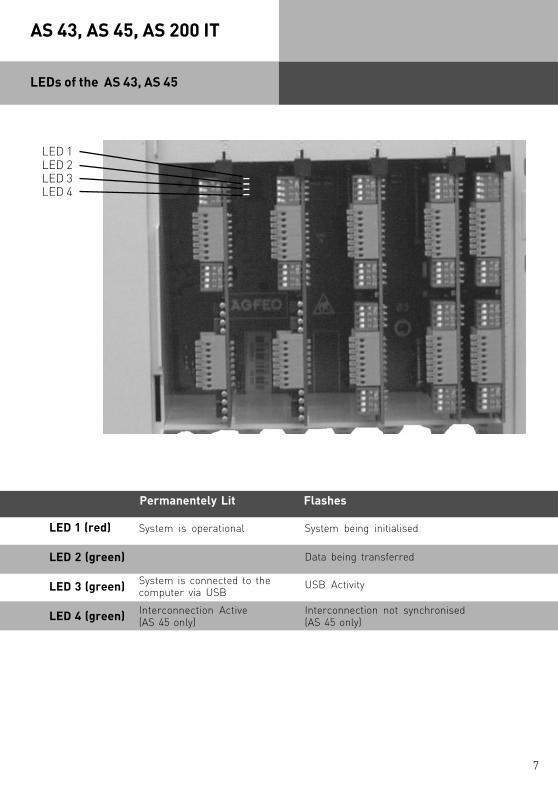
LEDs of the AS 43, AS 45
Permanentely Lit Flashes
LED 1 (red)
LED 2 (green)
LED 3 (green)
LED 4 (green)
System is operational
Interconnection Active(AS 45 only)
System is connected to thecomputer via USB
System being initialised
Data being transferred
Interconnection not synchronised(AS 45 only)
USB Activity
LED 1LED 2LED 3LED 4

8
AS 43, AS 45, AS 200 IT
Safety Notes
- Insert the module vertically, with the large connector strip pointing upwards, into the top handbottom guide slits of one slot.
- Carefully push the module down until the connectors engage and the latching lug of themodule latches into the lock.
- Pull the adhesive label showing the module’s connections off the information sheet (includedwith the module packaging).
- Stick the adhesive label over the module’s slot on the housing.
Installing and replacing modules
Pay attention to the safety notes- before installing or removing a module,- before connecting or disconnecting a connecting lead
1. Remove the telephone system’s 230 V mains plug from the socket.2. Remove the Western plugs of all external ISDN basic accesses from the telephone system, the
network terminator (NT) or the S0 bus.3. Touch the metal shield of the PC/ printer socket on the bottom of the telephone system briefly
with your finger. This will discharge any possible electro static charges, thus protecting thetelephone system’s lectrostatically sensitive components.
- Undo the module’s connecting leads. Mark the connecting leads clearly to avoid confusion onreconnection.
- Press the lock upwards until the module’s latching lug is free. Carefully pull the module outtowards you.
- Install the new module as described before.
Installing a Module
Replacing a Module
Installation of AS 200 IT
Instructions on how to open an AS 200IT, installation of modules and patchfield are available in theinstallation instruction of the AS 200 IT, Ref. Nr. 1101331

9
AS 43, AS 45, AS 200 IT
The K-Module 524
Connections:2 SO connections switchable internal /
external (external: PTP or PTMPinternal: PTMP)
4 Analogue Extensions (POT’s)
La1Lb1La2Lb2La3Lb3La4Lb4
b2 b1
EXT/INT
100R
100R
EXT/INT
a2 a1b1 b2a1 a2b2 b1a2 a1b1 b2a1 a2
S01
S02
a1
b1
a2
b2
Western plugto the NTBA orto the IAE socket
b2: whitea2: yellowb1: browna1: green
1....83: a24: a15: b16: b2
external S0
EXT/INT
You may connect any analogue apparatus to the system which has been approved forconnection to the public switched telephone network.
a/b-Apparatus is:- Telephone (2 wire Phone or POT) either LD or MF Dialling with Timed Break Recall (TBR) (60 –
800 ms)- LD Phones may only have limited feature access.- Fax machines Group 3- Telephone Answering Machines- Modem 56k (V.90 to 56600 bps, may reduce to 33600 bps due to quality of lines V.34+)Connect the analogue apparatus via 2 wires to the a and b wire (Speech Pair) of the systemport
Connection of wire:- Strip the cable by 11 mm.- Push the single wire all the way into the connection block without pressing the release catch.- To disconnect a wire, press the release catch with a small screwdriver while at the same time
pulling out the conductor
Connect Analogue Extensions

10
AS 43, AS 45, AS 200 IT
Switchable SO Connections
External S0-ConnectionYou may connect the external SO Connection to a System Access (PTP) or Standard Access(PTPM) line. Please refer to External SO Connection (RJ45 Socket).Use the enclosed ISDN Cable and connect the four wires to the SO connection block of themodule.- Push the wire all the way into the connection block without pressing the release catch.- Connector: a1 -green
b1 -browna2 -yellowb2 -white
- To disconnect a wire, press the release catch with a small screwdriver while at the sametime pulling out the conductor.- Guide the cable through the cable comb.
Termination Resistors for the external SO ConnectionSystem Access (PTP)– Both DIP Switches for the 100 Ohm Resistors must be closed or set to on. (Default Setting)
Standard Access (PTMP) - Both DIP Switches (Page 1-7/8) must be- closed or set to on if the connection is made directly onto the NTTP or on the last socket which
has no 100 Ohm Termination Resistors fitted.- open or set to off if the last socket has the 100 Ohm Termination Resistors installed or if the
telephone system is not the last ISDN device on a PTMP line.
Plug the ISDN Plug into the ISDN connection after completion of all installation work.
External S0 Connections
11
AS 43, AS 45, AS 200 IT
Internal S0 Connections
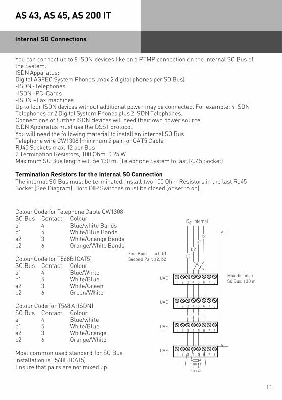
You can connect up to 8 ISDN devices like on a PTMP connection on the internal SO Bus ofthe System.ISDN Apparatus:Digital AGFEO System Phones (max 2 digital phones per SO Bus)-ISDN -Telephones-ISDN -PC-Cards-ISDN –Fax machinesUp to four ISDN devices without additional power may be connected. For example: 4 ISDNTelephones or 2 Digital System Phones plus 2 ISDN Telephones.Connections of further ISDN devices will need their own power source.ISDN Apparatus must use the DSS1 protocol.You will need the following material to install an internal SO Bus.Telephone wire CW1308 (minimum 2 pair) or CAT5 CableRJ45 Sockets max. 12 per Bus2 Termination Resistors, 100 Ohm 0.25 WMaximum SO Bus length will be 130 m. (Telephone System to last RJ45 Socket)
Termination Resistors for the Internal SO ConnectionThe internal SO Bus must be terminated. Install two 100 Ohm Resistors in the last RJ45Socket (See Diagram). Both DIP Switches must be closed (or set to on)
First Pair: a1, b1Second Pair: a2, b2
b1
b2
a1
a2
S0- internal
100 Ω
1UAE
2 3 4 5 6 7 8
1UAE
2 3 4 5 6 7 8
1UAE
2 3 4 5 6 7 8
1UAE
2 3 4 5 6 7 8
100 Ω
Max distance S0 Bus: 130 m
Colour Code for Telephone Cable CW1308SO Bus Contact Coloura1 4 Blue/white Bandsb1 5 White/Blue Bandsa2 3 White/Orange Bandsb2 6 Orange/White Bands
Colour Code for T568B (CAT5)SO Bus Contact Coloura1 4 Blue/Whiteb1 5 White/Bluea2 3 White/Greenb2 6 Green/White
Colour Code for T568 A (ISDN)SO Bus Contact Coloura1 4 Blue/whiteb1 5 White/Bluea2 3 White/Orangeb2 6 Orange/White
Most common used standard for SO Businstallation is T568B (CAT5)Ensure that pairs are not mixed up.

12
AS 43, AS 45, AS 200 IT
Installation and Termination of the S0 Bus
It is important that the S0 Bus will be terminated with 100 Ohm resistors on the end of the line.Without termination the signals will be reflected on the line end and returned - similar to waterwhen this hits an obstructions. The reflected signals will collide with the next received signalsand destroy these. The result is that the S0 Bus will become faulty. Even though with thetermination of four 100 Ohm resistors on either end of the "receive" and "transmit" circuit it maylook as if the line is under heavy load but the resistors will have hardly any influence on thesignalling voltage. A point to point installation will be terminated at the NTTP and the TelephoneSystem itself, it will be imperative that with a Bus installation the line will always be terminatedat the end of the circuit. Also, it is important that the line which is transmitting to the exchange isnot reversed between sockets. As the signals have positive and negative pulses, a telephone whichis sending positive signals my be received as negative on the other phone and may delete the posi-tive impulses of that phone. The result will be that the S0 Bus will become faulty.
Fault description and possible causes
Calls a dropped. Intermittent fault.- Check the connection between telephone system and the connected sockets / distribution
points.- Check that cables are correctly terminated. If possible use a meter and start at the system end.
The exchange, the internal S0 Bus and all connected apparatus must be disconnected beforemeasuring the line.
- Most cases will show a loose connection. Disconnect the cable from the system and socket andthen reconnect.
Only one apparatus at a time will function on the Bus.- Please check that the wires between sockets are not reversed. If this is the case then one
devise will function. However, more than one devise will cause interference between eachother.
High interference,instable lines, crackling in handset.- If the system is not operated via a plug in power supply, then it will be earthed via mains supply.
Heavy interferences via earth can lead to crackling and even disconnection of calls. In order toestablish if an earth problem exists, experiment and disconnect the earth momentarily or usean insulation transformer.
Interferences from other devices- Some devices such as mechanical bells have a large interference potential and can lead to call
disconnection.
13
AS 43, AS 45, AS 200 IT
Short and Extended Passive Bus InternalS0 Bus configuration
Some technical aspects should be observed on the installation of an ISDN Bus and may requiredifferent settings. The telephone system is sending impulses in a specific "frame". The telephoneexchange is expecting an answer of these frames from the connected telephone and devices. Thetime until an answer is received will vary and is depending on the cable length. The longer thecable the later the reply will be. The signal has to go through the cable twice (there an back). Dueto this a important requirment should be observed.The telephones should not be to far apart that due to the running time of the signal the first bit ofthe distant phone will not coincide with the second bit of the nearer phone. Due to this thereceiver of these bits cannot be seperated and the transmission will malfunction. Due to this twodifferent Bus settings may be selected.
Extended Passive Bus ( 0 to 1000 Metres)In this operation the receiver will search for the beginning of a receiving frame. With this it is ableto adjust to a phone which is near and has a short running time and to a phone which is far awayand has a long running time. Both at the same is not possible. On the contrary the search modeis very sensitive. Due to this the phone can only be apart for a maximum of 50 metres to ensurethat the impulses will be near to equal timing. This could be 400 metres and 450 metres or 25 and75 metres.
Short Passive Bus ( 0 to 130 Metres)The restriction of 50 metres between telephones on a bus installation is not always possible. Dueto this there is a second operational mode. In this mode the search facility is switched off. Thereceiver is expecting the time frame in a specified time window. This window is relative large andallows for a distance between telephones from 0 to 130 metres. For example a telephone mayhave a distance of 5 metres and another one of 130 metres from the exchange or telephonesystem. The maximum distance of a device to the exchange should not exceed 130 metres.However, this will also depend on the cable used. This mode is to be suggested for star wiringinstallation.You will find this option in the remote configuration tool in the "Option internal S0"
14
AS 43, AS 45, AS 200 IT
Lb7La7Lb8La8
Lb5La5Lb6La6
Lb3La3Lb4La4
Lb1La1Lb2La2
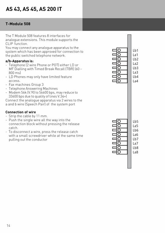
T-Module 508
The T Module 508 features 8 interfaces foranalogue extensions. This module supports theCLIP function.You may connect any analogue apparatus to thesystem which has been approved for connection tothe public switched telephone network.
a/b-Apparatus is:- Telephone (2 wire Phone or POT) either LD or
MF Dialling with Timed Break Recall (TBR) (60 –800 ms)
- LD Phones may only have limited featureaccess.
- Fax machines Group 3- Telephone Answering Machines- Modem 56k (V.90 to 56600 bps, may reduce to
33600 bps due to quality of lines V.34+)Connect the analogue apparatus via 2 wires to thea and b wire (Speech Pair) of the system port
Connection of wire- Strip the cable by 11 mm.- Push the single wire all the way into the
connection block without pressing the releasecatch.
- To disconnect a wire, press the release catchwith a small screwdriver while at the same timepulling out the conductor
15
AS 43, AS 45, AS 200 IT
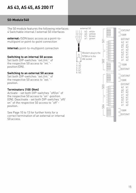
S0-Module 540
The S0 module features the following interfaces:4 Switchable internal / external S0 interfaces
external: ISDN basic access as a point-to-multipoint or point-to-point connection
internal: point-to-multipoint connection
Switching to an internal S0 accessSet both DIP-switches “ext./int.” ofthe respective S0 access to “int.”-position (ON).
Switching to an external S0 accessSet both DIP-switches “ext./int.” ofthe respective S0 access to “ext.”-position.
Terminators (100 Ohm)Activate - set both DIP-switches “off/on” ofthe respective S0 access to “on”-position(ON). Deactivate - set both DIP-switches “off/on” of the respective S0 access to “off”-position.
See Page 10 to 13 for further hints for acorrect termination of an external or internalS0 access.
b2 b1
EXT/INT
100R
EXT/INT
100R
100R
EXT/INT
100R
EXT/INT
a2 a1b1 b2a1 a2b2 b1a2 a1b1 b2a1 a2
S01
S03
S02
S04
a1
b1
a2
b2
Western plug to theNTBA or to the IAE socket
b2: whitea2: yellowb1: browna1: green
1....83: a24: a15: b16: b2
external S0
EXT/INT
b2 b1a2 a1b1 b2a1 a2b2 b1a2 a1b1 b2a1 a2
EXT/INT

16
AS 43, AS 45, AS 200 IT
Up0-Module 508
The UP0-Module 508 can support of up to eightAGFEO Up0 System Telephones. Please note thatin order to operate an Up0 Module it will be impe-rative that a system firmware from 7.5 isinstalled.
Connections of Extensions:
- Strip the cable by 11 mm.- Push the single wire all the way into the
connection block without pressing the releasecatch.
- To disconnect a wire, press the release catchwith a small screwdriver while at the sametime pulling at the wire.
- The wires are to be connected to contact 4 and 5of the socket.
- The Up0 Module is NOT polarity conscious.- Please note you can only connect 1 apparatus to
each Up0 connection. A termination resistor isNOT required.
Lb7La7Lb8La8
Lb5La5Lb6La6
Lb3La3Lb4La4
Lb1La1Lb2La2

17
AS 43, AS 45, AS 200 IT
You may connect up to 4 analogue exchange lines to this module. The module supportsDTMF dialling and CLIP, however the latter would have to be enabled by your networkoperator and may be chargeable. Should your network operator support CLI, then this will bepresented via the AL4504 module to the system. CLIP* will also be entered into the call logand call management system. (*CLIP (Calling Line Identity Presentation) is a feature whichwill display the telephone number and or name of the calling party before you answer thecall.)The PABX compares the received CLIP information with the entries of the systemtelephone book and if a match is found will replace the calling telephone number with thename as it is entered in the system telephone book. This information will also be used by thecall log and call management system. CLI will also be presented to analogue caller idtelephones. If necessary the AL4504 can be updated.
Differences to an ISDN Line
Unlike to the protocol based ISDN line, the apparatus connected to the analogue line will notreceive a call progress report from the telephone network. For instance the connected deviceon an analogue line will not receive a confirmation that the called party has answered thecall. This will result in the following difference between an analogue exchange line and anISDN line:The moment the exchange line has been seized is the time the call will be logged as to havetaken place. TK Suite Bill will log a call as being completed or have taken place as soon as anexchange line has been seized, even if the line is still ringing or engaged. MF overdialling ispossible but will not be recognised by the system as such. This will result that the completetelephone number and overdialled number will be stored in the call log and last number redial.
AL-Module 4504
CLIP at the Analogue Exchange
In default the PABX is set that an incoming call will ring an extension without using the CLIPfunction. However, you may enable this function by changing the setting in ‘Wait for CLIP‘.The forwarding of the CLIP information from the telephone network may take up to 5seconds, during this time the system will be idle. Therefore the extensions will ring with adelay of up to 6 seconds. It may be useful to make use of the function ‘Wait for CLIP‘ if thisinformation will not be displayed at your extension, or if you use a call filter or SMSmessaging via the analogue line.
Notes
Further installation and programming information of the AL Module 4504 are available theinstallation instruction of the AL-Module 4504, Ref. Nor. 1100692.

18
AS 43, AS 45, AS 200 IT
Remote programming and Remote Updating of the PABX and or AL Module 4504 will not bepossible when using an analogue exchange line only.The AL-Module 4504 DOES NOT support meter pulses from the exchange. To avoid malfunction,please ensure that meter pulses are disabled from the relevant telephone provider.
Important Notes
Connection of Analogue Lines
Connecting the wires:- Strip 11 mm of insulation from the wires.- Slide the individual wires into the clip up to the insulation without pressing the spring clip.- Push- To release a wire, press the spring clip down using a suitable object (small screwdriver) and pull
out the wire.
Tip 1Ring 1Tip 2Ring 2Tip 3Ring 3Tip 4Ring 4
Line 1
Line 2
Line 3
Line 4

19
AS 43, AS 45, AS 200 IT
The AGFEO K-Module 544, is for the Telephone Systems AS 43, AS 45 and AS 200 IT fromfirmware 7.1 and will support the following three communications sections. These are:Alarm Section:4 alarm input contacts with independent voltage supply + 12 V 250 mADoor Phone Section:3 Analogue Extensions (SLT) with CLIP for analogue phones, fax machines or AGFEO DoorPhones. With 2 Switching Relays.Audio Section:Audio input with a 3.5 mm socket for MoH and background music. Audio output withsymmetrical 0.8 Watt/8 Ohm for loudspeakers, switchable as pre-amp output (asymmetrical) foran external amplifier.
AL 1 IN
U-1
KT 1
LS 1
AL 1 -
U-2
KT 2
LS 2
AL 2 IN
La1
TO 1
AUDIO-ASYM
AL 2 -
Lb1
TO 2
GND
AL 3 IN
La2
TS 1
AUDIO IN
AL 3 -
Lb2
TS 2
AL 4 IN
La3
REL 1-1
AL 4 -
Lb3
REL 1-2
AL +
REL 2-1
AL +
REL 2-2
Connections of K-Module 544
Signalling Input Sensor 1GroundSignalling Input Sensor 2GroundSignalling Input Sensor 3GroundSignalling Input Sensor 4Ground12V Supply Voltage12V Supply Voltage
Transformer for Dooropener for doorphone with 2-wire-standard connection
Extension 1 / Doorphone Connection for doorphone with 2-wire-standard connection
Extension 2 / Doorphone Connection for TFE FTZ 123 D 12
Extension 3 / analogue 2-wire doorphone (e.g., AGFEO TFE 2/4)
Bell Push for FTZ 123 D 12
TO for TFE FTZ 123 D 12
TS for TFE FTZ 123 D 12
Switching Relay 1
Switching Relay 2
Audio output with symmetrical 0.8 Watt/8 Ohm for loudspeakers
pre-amp output (asymmetrical) for an external amplifier
Audio Input for MoH
K-Module 544
Notes
Further installation and programming information of the K-Module 544 are available theinstallation instruction of the K-Module 544, Ref. Nor. 1101366.

20
AS 43, AS 45, AS 200 IT
System Interconnection
It is possible to interconnect 2 AS 45‘s or 2 AS 200 IT´s and therefore increase the maximumnumber of port to 80. Of these 48 ports may be used for System Phones or System DECT’s. Themodules, with the exception of the LAN Module, may be inserted into any module slot of theinterconnected telephone system. The following points with reference to the interconnection oftwo systems should be observed:- If the telephone system is operated on a Point to Multi Point line, then a permanent active
external S0 must be connected to the first S0 of the Master Cabinet.
- If the telephone system is operated on a Point to Point line, then at least one external S0 mustbe connected to the Master Cabinet.
- Like with the AS 45 up to 48 STE 30‘s or STE 40‘s may be connected.
- System programming will only be possible via the serial- or USB connection of the mastercabinet. These connections are without function on the slave unit. Programming via the S0 Busis possible on either cabinet.
- CTI via the serial- or the USB connection will only be available at the master cabinet. If youwant to utilise CTI from various computers (Network), then a telephony server must be madeavailable at the master system.
- Both system must be of the same firmware level. For this the master system must be updated,the slave system will automatically being updated.
- Disconnect both AS 45‘s or AS 200 IT´s from the Mains Socket.
- Connect the “Master” socket from one system to the “Slave” socket of the other system.Please use a shielded network cable (at least CAT5). Please note that the length of this cablecannot exceed 1 metre.
- Power up both systems.
- Please wait until LED 4 is permanently lid. As before, you now can program the system via TKSuite.
Master Connection:The system on which thisconnection is used, is theMASTER SYSTEM(CABINET)
Slave Connection:The system on which thisconnection is used, is theSLAVE SYSTEM(CABINET)

21
AS 43, AS 45, AS 200 IT
Telefonanlage(9pol. Stecker)
23
5
78
Drucker(25pol. Stecker)
23
5678
20
Connecting a printer for printingconnection charges
You can connect any printer to the telephone system’s RS 232C interface to print out connectionrecords. For connection, you need a cable that corresponds to the pin assignments given below(maximum length 3 m).Your printer must be set as follows:- 9600 baud- 8 bits- 1 stop bit- no parityTo print out connection records, the printer must be on all the time and must be connectedto the telephone system. The telephone system stores 2000 connection records and the totalconnection charges, even in the event of a power failure.
You have installed the system. However, before you can make a call you must do the following:
- Connect the extensions. You may connect any apparatus which you are allowed to connect tothe public switched telephone network.
- Connect the RJ 45 plug to the ISDN network or connect the relevant connection cable to theanalogue network.
- Switch on the telephone system by plugging the mains plug into the mains socket.
Programming to the users requirement can be carried out via the connection of a PC. Theremote programming of the system may be carried out via your dealer.
Commissioning
Notes
To avoid calling wrong telephone numbers please ensure that the following is carried out.After installation of the system please dial from an analogue MF telephone a single digit,this ensures that the system recognises the correct dialling method for the relevantextension. Should you change to a telephone which is dialling in LD, then you must dial adigit higher then 2. Should you operate two telephone on one port, then you must ensurethat both phones connected are of the same dialling method.
telephone system(9-Pole connector)
printer(25-Pole connector)

22
AS 43, AS 45, AS 200 IT
Tecnical Data
ModularISDN Telephone System with 5 Expansion Slotsand On board Interconnection( AS 43: 3 Expansion Slots, no Interconnection)
2 S0 connections switchable internal / external, 4 Analogue Extensions(POT’s)
4 S0 connections switchable internal / external
8 Analogue Extensions (POT’s)
4 Analogue Trunk Lines
8 Up0 Ports
4 alarm input contacts, 3 Analouge Extensions or 1 FTZ 123D12 DoorPhone, 1 two wire Door Phone and 1 analogue two wire doorphone (e.g.AGFEO TFE 2/4), 2 switching Relays, 1 audio ouptut symmetrical forloudspeakers, switchable as pre-amp output (asymmetrical) for anexternal amplifier, 1 Audio Input for external MoH
26 x 32 x 12 cm (High x Width x Depth)
3,4 kg
5 °C to 40 °C / -25 °C to +70 °C
max. 70 % (none condensing)
230 VAC, +6%/-10%, 50 Hz
Pmax = 60 WPmax = 40 W
PTP or PTMP connections, Euro ISDN 2e
via RJ 45 Socket and enclosed connection cable
SO connection internal / external switchable (DIP Switches)external: PTP or PTMP connection Euro ISDN 2e (DSS1)internal: PTMP connection, Euro ISDN 2e (DSS1)
Specification
Expansion Modules
- K-Module 524
- S0-Module 540
- T-Module 508
- AL-Module 4504
- Up0-Module 508
- K-Module 544
Measurements
Weight
Ambient temperature
- Operation/Storage
Humidity
Mains Connection
Power Consumption- AS 45- AS 43
External S0 Connectionfixed- Connection
Switchable Connection

23
AS 43, AS 45, AS 200 IT
- Connection
- Length
- Power Consumptioninternal S0
- ISDN-Apparatus
Up0-Connection
- Connection
- Length
Analogue Apparatus
- Distance
- Connection
- Dial Method
- Enquiry Button
PC/ Printer Connection
- Range/ Level
- Connector
USB Connection
- Cable Length
Switching Relays
- Contact Load
Audio Output
Audio Input
4 wire spring loaded connectors
max lenght of internal SO Connection dependent on the mode- Short passive Bus 130 m- Extended passive Bus 1000 m
4,5 Watts
max. 8
2 wire spring loaded connectors
800 m
2 x 50 Ohm (diam. 0,6 mm, 800 m)
2 wire spring loaded connectors
DTMF or LD
Flash (80 - 600 ms).
RS 232C
3 m / +/- 5 V
9 pin D-Socket
Universal Serial Bus
3 m
Spare contact with surge arrestor 1 kOhm / 100 nF30 VDC/1 A or 125 VAC/0.5A, resistive load
1 kOhm, 100 nF
0,8 Watt /8 Ohm symmetrical0,4 Watt /4 Ohm asymmetrical
Initial resistance 50 K Ohm
Tecnical Data

Ident no. 1101332Subject to change withoutnotice. No liability can beaccepted for errors contained inthis document.Printed in Germany0067
AGFEO GmbH & Co. KGGaswerkstr. 8D-33647 BielefeldInternet: http://www.agfeo.com
The crossed out wheeled bin on the product means that this belongs to the group of Electro- andelectronic apparatus.
In this context you are directed by the European regulation to dispose of used apparatus- at the point of buying an item of equal proportion / value- at the local available collection point for disposalWith this you will participate in the reuse of material and valorisation of disused electric- and electronic apparatus, which otherwise could be a health hazard and be negative to the environment.