arXiv:quant-ph/0008039v2 9 Aug 2000
19
arXiv:quant-ph/0008039v2 9 Aug 2000 Long distance entanglement based quantum key distribution Gr´ egoire Ribordy, J¨ urgen Brendel † , Jean-Daniel Gautier, Nicolas Gisin, and Hugo Zbinden Gap-Optique, Universit´ e de Gen` eve, 20 rue de l’Ecole-de-M´ edecine, 1211 Gen` eve 4, Switzerland Email: [email protected] † Present address: Luciol Instruments SA, 31 Chemin de la Vuarpilli` ere, 1260 Nyon, Switzerland (October 29, 2018) A detailled analysis of quantum key distribution employing entangled states is presented. We tested a system based on photon pairs entangled in energy- time optimized for long distance transmission. It is based on a Franson type set-up for monitoring quantum correlations, and uses a protocol analogous to BB84. Passive state preparation is implemented by polarization multiplexing in the interferometers. We distributed a sifted key of 0.4 Mbits at a raw rate of 134 Hz and with an error rate of 8.6% over a distance of 8.5 kilometers. We discuss thoroughly the noise sources and practical difficulties associated with entangled states systems. Finally the level of security offered by this system is assessed and compared with that of faint laser pulses systems. I. INTRODUCTION Quantum key distribution (QKD), the most advanced application of the new field of quantum information theory, offers the possibility for two remote parties - Alice and Bob - to exchange a secret key without meeting or resorting to the services of a courier. This key can in turn be used to implement a secure encryption algorithm, such as the “one-time pad”, in order to establish a confidential communication link. In principle, the security of QKD relies on the laws of quantum physics, although this claim must be somewhat softened because of the lack of ideal components - in particular the photon source and the detectors. After the first proposal by Bennett and Brassard [1], various systems of QKD have been introduced and tested by groups around the world (see [2–5] for recent experiments). Until recently, all QKD experiments relied on strongly attenuated laser pulses, as an approxima- tion to single photons, because of the lack of appropriate sources for such states. Although this solution is the simplest from an experimental point of view, it suffers from two impor- tant drawbacks. First, the fact that a fraction of the pulses contains more than one photon constitutes a vulnerability to certain eavesdropping strategies. Second, the maximum trans- mission distance is reduced, because of the fact that most of the pulses are actually empty. Both points are discussed in more detail below. Ekert proposed in 1992 a protocol utilizing entangled states for QKD [6]. Photon pair sources making use of parametric downconversion are relatively simple and flexible. They have been used for several years and were exploited for example for tests of Bell inequalities [7–9]. These experiments demonstrated that entanglement of photon pairs can be preserved over long distances in optical fibers, and could thus allow the implementation of QKD. Recently, research groups performed the first entangled photons pairs QKD experiments [10–12]. Both Naik [11] and Jennewein [12] chose to use photons at a wavelength of 702 nm, entangled in polarization for their investigations. Although this choice is appropriate for free space QKD, it prevents any transmission over a distance of more than a few kilometers in optical fibers. Polarization entanglement is indeed not very robust to decoherence, and attenuation at this wavelength is rather high in optical fibers. Tittel et al. used photons 1
Transcript of arXiv:quant-ph/0008039v2 9 Aug 2000

arX
iv:q
uant
-ph/
0008
039v
2 9
Aug
200
0
Long distance entanglement based quantum key distribution
Gregoire Ribordy, Jurgen Brendel†, Jean-Daniel Gautier, Nicolas Gisin, and Hugo ZbindenGap-Optique, Universite de Geneve, 20 rue de
l’Ecole-de-Medecine, 1211 Geneve 4, Switzerland
Email: [email protected]†Present address: Luciol Instruments SA, 31 Chemin de la
Vuarpilliere, 1260 Nyon, Switzerland
(October 29, 2018)
A detailled analysis of quantum key distribution employing entangled statesis presented. We tested a system based on photon pairs entangled in energy-time optimized for long distance transmission. It is based on a Franson typeset-up for monitoring quantum correlations, and uses a protocol analogous toBB84. Passive state preparation is implemented by polarization multiplexingin the interferometers. We distributed a sifted key of 0.4 Mbits at a raw rateof 134 Hz and with an error rate of 8.6% over a distance of 8.5 kilometers. Wediscuss thoroughly the noise sources and practical difficulties associated withentangled states systems. Finally the level of security offered by this systemis assessed and compared with that of faint laser pulses systems.
I. INTRODUCTION
Quantum key distribution (QKD), the most advanced application of the new field ofquantum information theory, offers the possibility for two remote parties - Alice and Bob- to exchange a secret key without meeting or resorting to the services of a courier. Thiskey can in turn be used to implement a secure encryption algorithm, such as the “one-timepad”, in order to establish a confidential communication link. In principle, the security ofQKD relies on the laws of quantum physics, although this claim must be somewhat softenedbecause of the lack of ideal components - in particular the photon source and the detectors.After the first proposal by Bennett and Brassard [1], various systems of QKD have been
introduced and tested by groups around the world (see [2–5] for recent experiments). Untilrecently, all QKD experiments relied on strongly attenuated laser pulses, as an approxima-tion to single photons, because of the lack of appropriate sources for such states. Althoughthis solution is the simplest from an experimental point of view, it suffers from two impor-tant drawbacks. First, the fact that a fraction of the pulses contains more than one photonconstitutes a vulnerability to certain eavesdropping strategies. Second, the maximum trans-mission distance is reduced, because of the fact that most of the pulses are actually empty.Both points are discussed in more detail below.Ekert proposed in 1992 a protocol utilizing entangled states for QKD [6]. Photon pair
sources making use of parametric downconversion are relatively simple and flexible. Theyhave been used for several years and were exploited for example for tests of Bell inequalities[7–9]. These experiments demonstrated that entanglement of photon pairs can be preservedover long distances in optical fibers, and could thus allow the implementation of QKD.Recently, research groups performed the first entangled photons pairs QKD experiments
[10–12]. Both Naik [11] and Jennewein [12] chose to use photons at a wavelength of 702 nm,entangled in polarization for their investigations. Although this choice is appropriate forfree space QKD, it prevents any transmission over a distance of more than a few kilometersin optical fibers. Polarization entanglement is indeed not very robust to decoherence, andattenuation at this wavelength is rather high in optical fibers. Tittel et al. used photons
1

pairs correlated in energy and time and with a wavelength where the attenuation in fibers islow, but their actual implementation was not optimized for long distance transmission [10].In this paper, we present the first system for QKD with entangled photon pairs exploiting
an asymmetric configuration optimized for long distance operation. In addition, we believethat it offers a particularly high level of security. We introduce first the principle of oursystem, then discuss experimental results obtained under laboratory conditions. Finally,we compare it with other experiments and evaluate its advantages and drawbacks, beforeconcluding.
II. PRINCIPLE OF THE QKD SYSTEM
When designing a QKD system where photons are exchanged between Alice and Bob,one must first choose on which property to encode the qubits values. Although polarizationis a straightforward choice, it is not the most appropriate one when transmitting photonpairs over optical fibers. The intrinsic birefringence of these fibers, also known as polarizationmode dispersion, associated with the large spectral width (typically 5 nm FWHM at 800 nm)of the down-converted photons yields rapid depolarization. Considering that such photonshave typically a coherence time of the order of 1 ps, and that standard telecommunicationsfibers exhibit a polarization mode dispersion of 0.2 ps /
√km, one sees that the polarization
mode separation already becomes substantial after a few kilometers. This fact indicates thatpolarization is not robust enough for long distance QKD in fibers when using photon pairs.A solution is therefore to encode the values of the qubits on the phase of the photons. Inaddition, previous experiments demonstrated that the polarization transformation inducedby an installed optical fiber changes sometimes abruptly. An active polarization alignmentsystem is consequently necessary to compensate these fluctuations.A second important parameter for a QKD system is the wavelength of the photons. Two
opposite factors influence this choice. On the one hand, the attenuation in optical fibersdecreases with an increase of the wavelength from 2 dB /km at 800 nm to a local mini-mum of 0.35 dB / km at 1300 nm and an absolute minimum of 0.25 dB / km at 1550 nm.On the other hand, photons with lower energy - or longer wavelength - tend to be moredifficult to detect. Below 900 nm, one typically uses commercial modules built around asilicon avalanche photodiode (Si APD) biased above breakdown. They offer good quantumdetection efficiency (typically 50%), low noise count rate (100 Hz), and easy operation. Inthe so-called second telecom window, germanium avalanche photodiodes (Ge APD) can beused. Their performance is not as good as that of Si APD’s and they require liquid nitrogencooling. Finally, only indium gallium arsenide avalanche photodiodes (InGaAs APD) exhibitsufficient detection efficiency in the third telecom window around 1550 nm. They have thesame drawbacks as Ge APD’s, but also require gated operation to yield low enough darkcounting rates. Taking into account these factors, one can conclude that up to a few kilo-meters, 800 nm is a good choice. In addition, beyond 30 to 40 km, the only real possibilityis to operate the system at 1550 nm, because fiber attenuation becomes really critical.
A. QKD Protocol
Our system is based on a Franson arrangement [13]. It exploits photon pairs entangled inenergy-time, where both the sum of the energy and of the momenta of the down-convertedphotons equal those of the pump photon. A source located between Alice and Bob generatessuch pairs, which are split at its output (see Fig. 1 a). One photon is sent to each party downquantum channels. Both Alice and Bob possess an unbalanced Mach-Zehnder interferometer,with photon counting detectors connected at its outputs. When considering a given photonpair, four events can yield coincidences between one detector at Alice’s and one at Bob’s.First, the photons can both propagate through the short arms of the interferometers. Then,
2

one can take the long arm at Alice’s, while the other takes the short one at Bob’s. Theopposite is also possible. Finally, both photons can propagate through the long arms. Whenthe path differences of the interferometers are matched within a fraction of the coherencelength of the down-converted photons, the short - short and the long - long processes areindistinguishable and yield thus two-photons interference, provided that the coherence lengthof the pump photons is longer than the path difference. If one monitors these coincidencesas a function of time, three peaks appear. The central one is constituted by the interferingshort-short and long-long events. It can be separated from non-interfering ones, by placinga window discriminator. Only interfering processes will be considered below.We implemented a protocol analogous to BB84. Ekert et al. showed in [14] that the
probabilities for Alice and Bob to get correlated counts (the photons choose the same portat Alice’s and Bob’s) and anticorrelated counts (they choose different ports) are given by
Pcorrelation = P (A = 0;B = 0) + P (A = 1;B = 1) =1
2[1 + cos (φA + φB)] (1)
Panticorrelation = P (A = 0;B = 1) + P (A = 1;B = 0) =1
2[1− cos (φA + φB)] (2)
where Alice’s phase φA and Bob’s phase φB can be set independently in each interferom-eter. The results of Alice’s and Bob’s measurements are represented by A and B. They cantake values of 0 or 1 depending on the detector that registered the count. One sees that ifthe sum of the phases is equal to 0, Pcorrelation = 1 and Panticorrelation = 0. In this case,Alice can deduce that whenever she gets a count in one detector, Bob will also get one in theassociated detector. If both Alice and Bob set their phases to 0, they can exchange a keyby associating a bit value to each detector. However, if they want their system to be secureagainst eavesdropping attempts, they must implement a second measurement basis. Thiscan for example be done by adding a second interferometer to their systems (see Fig. 1 b).Now, when reaching an analyzer, a photon chooses randomly to go to one or the other inter-ferometer. The phase difference between Alice’s interferometers is set to π/2, whereas theone between Bob’s to −π/2. If both photons of a pair go to associated interferometers, thesum of the phase they experience is 0. We obtain again the correlated outcomes discussedabove. On the contrary, if they go to different interferometers, the sum is ±π/2. In thiscase, one finds that Pcorrelation = 1
2and Panticorrelation = 1
2. Alice’s and Bob’s outcomes
are then not correlated at all. They perform incompatible measurements. After exchanginga sequence of pairs, the parties must of course go through the conventional steps of keydistillation, as in any QKD system: key sifting, error correction and privacy amplification[15].
B. Photon Pairs Configuration
Let us now discuss the choice of wavelength for the photons of the pairs. As mentionedearlier, when transmitting photons over long distances, one should select a wavelength of1550 nm to minimize fiber attenuation. However, detectors sensitive to such photons requiregated operations in order to keep the dark counting rates low. Therefore, we selected anasymmetrical configuration where only the photon travelling to Bob has this wavelength,while the one travelling to Alice has a wavelength below 900 nm. She can consequentlyuse free running Si APD detectors. Whenever she gets a click, she sends a classical signalto Bob to warn him to gate his detectors. The source is located very close to Alice’sinterferometers, to keep fiber attenuation negligible (see Fig. 2). One should note that insuch an asymmetrical configuration, the losses in Alice’s apparatus seem to be unimportant.When a photon gets lost in Alice’s analyzer, she does not send a classical signal to Bob,who in turns does not gate his detectors. Such an event can thus not yield a false count
3

through detector noise. A second possibility is to utilize one photon of the pair simplyto generate a trigger signal, indicating the presence of the other one. This solution is notoptimal. The second photon must indeed be sent through a preparation device featuringattenuation, which will reduce its probability to be detected by Bob.Systems using pairs of photons entangled in energy-time are more sensitive to chromatic
dispersion spreading in the transmission line than faint pulse set-ups, because of the rela-tively large spectral width of the pairs. Indeed, interfering events are discriminated fromnon-interfering ones by timing information. Spreading of the photons between Alice and Bobinduced by chromatic dispersion must thus be kept to a minimum. For example, assuminga spectral width of 6 nm, an impulsion launched in a standard singlemode fiber featuring atypical dispersion coefficient of 18 ps nm−1 km−1 at 1550 nm would spread to 1 ns after 10km of fiber. This effect can be avoided by using dispersion shifted fibers (DS-fibers) withtheir dispersion minimum close to the down-converted wavelength. It is also possible tocompensate dispersion (see [16]), although it implies additional attenuation.
C. Characterizing the System
In order to characterize our new system and assess its advantages over other set-ups, weintroduce in this section the equations expressing the quantum bit error rate (QBER) andthe sifted key distribution rate.In principle, when an eavesdropper - Eve - performs a measurement on a qubit exchanged
between Alice and Bob, she induces a perturbation with non-zero probability, yielding errorsin the bit sequence. These discrepancies reveal her presence. Nevertheless in practicalsystems, errors also happen because of experimental imperfections. One can quantify thefrequency of these errors as the probability of getting a false count over the total probabilityof getting a count (see Eq. (3)). In the limit of low error probability, this ratio can beapproximated by the probability of getting an incorrect count over the probability of gettinga correct one. As discussed above, Bob’s detectors are operated in gated mode and theseprobabilities must thus be calculated per gate. In addition, we will consider only the caseswhere compatible bases are selected by Alice and Bob.
QBER =prob. incorrect count
prob. incorrect + correct count≈ prob. incorrect count
prob. correct count(3)
The correct count probability is expressed as the product of several terms. The first oneis µ, the probability of having a photon leaving the source in the direction of Bob wheneverAlice detects a photon and sends a classical pulse. Then come the probabilities TL and TB
for this photon to be transmitted respectively by the fiber link and by Bob’s apparatus. Thenext factor, qinterf , is equal to
1
2in our system and takes into account the fact that only half
of the photons will actually yield interfering events that can be used to generate the key.The factor ηD represents the quantum detection efficiency of Bob’s detectors. Finally, theterm qbasis accounts for the cases where Alice and Bob perform incompatible measurements.It is equal to 1
2for symmetrical basis choice.
Pcorrect = µ · TL · TB · qinterf · ηD · qbasis (4)
The probability of getting a false count per gate can be thought of as the sum of threeterms. It can arise first through a detector error. Each one of our four detectors can registera noise count. It will yield an error in 25% of the cases, a correct bit also in 25% of thecases and an incompatible measurement in the remaining 50%. It is thus accounted for bythe probability pcs (= 4 · pcs · 1
4).
Pincorrect = pcs + µ · TL · TB · qinterf · ηD · qbasis · popt + ν · TL · TB · qinterf · ηD · qbasis · qacc(5)
4

The second term corresponds to the cases where, because of imperfect phase alignment ofthe interferometers, a photon chooses the wrong output port of the interferometer. It is givenby the product of the probability of getting a correct count multiplied by the probabilitypopt for the photon to choose the wrong port. In an interferometric system, it stems fromnon-unity visibility V , and is given by the following equation.
popt =1− V
2(6)
Finally, the last term takes into account the probability of getting a count from an acci-dental coincidence. It is given by the product of the probability ν of having an uncorrelatedphoton within a gate, with the probability for this photon to reach Bob’s system, and bedetected in the compatible basis. Because of the fact that it is not correlated with Alice’s,this photon will choose the output randomly and yield a false count in 50% of the cases,and a correct one also in 50%. This is accounted for by the factor qacc, which is equal to 1
2.
These three components can be separated into three QBER contributions as in Eq. (7).These formula are general and thus still valid for other systems.
QBER = QBERdet +QBERopt +QBERacc (7)
QBERdet =pcs
µ · TL · TB · qinterf · ηD · qbasis(8)
QBERopt =µ · TL · TB · qinterf · ηD · qbasis · popt
µ · TL · TB · qinterf · ηD · qbasis= popt (9)
QBERacc =ν · TL · TB · qinterf · ηD · qbasis · qacc
µ · TL · TB · qinterf · ηD · qbasis= qacc
ν
µ(10)
One should note that if the basis choice was implemented actively, only two out of thefour detectors at Bob’s would be gated for a given bit. This implies that both QBERdet andQBERacc would be reduced by a factor of two. In principle, active switching ensures thusa gain of a factor 2 in QBERdet, corresponding to approximately 10 km of transmissiondistance at 1550 nm. In practice, this is not true because of the additional losses inducedby devices used to perform active bases choices (Pockel cells or LiNbO3-phase modulatorsfor example).When the length of the fiber link is increased, TL decreases. The probability of getting
a right count is reduced, while the probability of registering a dark count remains constantand QBERdet thus increases. On the other hand, as they do not depend on TL, bothQBERopt and QBERacc remain unchanged. When exchanging key material over long dis-tances, QBERdet becomes consequently the main contribution and sets an ultimate limiton the span. In order to maximize the distance, one should clearly choose the best detec-tors available, and maximize the correct count probability. In systems exploiting faint laserpulses, it is essential that the multiphoton pulse probability is low to ensure security. In thiscase, one selects for µ a value well below unity, which reduces the correct count probability.A given QBER is thus reached for a shorter transmission distance. Setting this parameterto 0.1 - a typical value - instead of 1 has the same effect on QBERdet as adding fiber atten-uation of 10 dB, corresponding to a distance of about 40 km at 1550 nm. One sees clearlya first advantage of using photon pairs instead of faint laser pulses. This issue is discussedin more details in Sec. V.Unfortunately, additional factors reduce this advantage. Comparing the predicted perfor-
mance of our photons pairs system with that of a well tested faint pulses system like our“plug & play” set-up [5], we see that the ratio of QBERdet for a given transmission distanceis in theory equal to
5

QBERp&pdet
QBERdet
=µ · qinterf
2 · µp&p · qp&pinterf
=5
2(11)
This results is obtained by setting qp&pinterf = 1 and µp&p = 0.1 for the “plug & play” and
qinterf = 1
2and µ = 1 for our photon pairs system. The factor 2 in the denominator comes
from the fact that active basis selection is performed with the ”plug&play” system. Theother factors are assumed to be identical and they just cancel out. This means that ournew system should be able to handle 4 dB of additional fiber attenuation, corresponding toapproximately 16 km at 1550 nm. However, one should note that photon pairs systems sufferfrom an additional contribution to their error rate - QBERacc - which somehow reduces thisadvantage. Although it is important, this span increase would not revolutionize the potentialapplications of QKD over optical fibers.Finally, it is possible to estimate the actual raw key creation rate (after sifting, but before
distillation) by multiplying the probability of getting a right count by the counting rateregistered by Alice.
Rraw = fAlice · Pcorrect (12)
The quantity fAlice represents the repetition frequency and Pcorrect is given by Eq. (4).One can then apply correction factors to estimate the distilled key rate [17].
III. IMPLEMENTATION OF THE SYSTEM
Now that the principles of QKD using photon pairs entangled in energy-time have beendiscussed, we can consider the actual implementation of the system. It consists of four basicsubsystems: the photon pair source, Alice’s interferometer, Bob’s interferometer, and theclassical channel (Fig. 2). We also discuss the procedure used to measure and adjust thepath differences of the interferometers.
A. The Photon Pair Source
The source is basically made up of a pump laser, a beam shaping and delivery opticalsystem, a non-linear crystal and two optical collection systems (see Fig. 3). It is built withbulk optics. The pump laser is a GCL-100-S frequency doubled-YAG laser manufactured byCrystalaser. It emits 100 mW of single mode light at 532 nm. Its spectral width is narrowerthan 10 kHz. This corresponds to a coherence length of about 30 km for the pump photons,and yields in turn a high visibility for the two-photons interference. Its frequency stabilitywas verified to be better than 50 MHz per 10 minutes. This is an important parameter sincethe wavelength of the pump photons controls the wavelengths of the down-converted photons.These must remain stable during a key distribution session, because they determine therelative phases the photons experience in the interferometers. The collimated beam passesfirst through a half-wave plate, which rotates its linear polarization state to horizontal. Itgoes then through a keplerian beam expander (×2). It passes then a dispersive prism and aSchott BG39 band pass filter (T = 98% at 532 nm, and T = 10−4 at 1064 nm), in order toremove any infrared light that might mask actual photon pairs. Both of these componentsare aligned so that the angle between their surfaces and the incident beam is close to theBrewster angle, in order to minimize pump power loss by partial reflection. The beamis then reflected by a metallic mirror before going through a pinhole, which complementsour simple monochromator. It is then focused on the KNbO3 non-linear crystal through abiconvex achromat with 100 mm focal length. The crystal measures 3 (φ-plane) x 4 (θ-plane)x 10 mm3. It is cut with a θ-angle of 22.95◦and allows collinear down-conversion at 810nm and 1550 nm when kept at room temperature and illuminated normally with a pump
6

at 532 nm. Its first face is covered with AR coating for 532 nm, while the second one hasAR coating for 810 and 1550 nm. The crystal can be slightly rotated (± 5◦) to tune thepump incidence angle. This parameter is used to adjust the down-converted wavelengths.The down-converted beams are then split by a dichroic mirror aligned at 45◦ incidence. Thephotons at 810 nm experience a transmission coefficient of approximately 80%, while the1550 nm ones experience a reflection coefficient of more than 98%. The short wavelengthbeam is then collimated by a biconvex achromat with a focal length of 150 mm. A set of twouncoated filters is then used to block off the pump light. One should avoid fluorescence inthis process, in order to minimize the probability of recording coincidences from uncorrelatedphotons. This is achieved by using first a low fluorescence Schott KV550 long pass filter(T=20% at 532 nm) to reduce the pump intensity, before blocking it with a Schott RG715long pass filter. The 810 nm photons are then focused onto the core of a singlemode fiber(cutoff wavelength <780 nm, mode field diameter = 5.5 µm) by a collimator (focal length= 11 mm) with FC/PC receptacle.After being reflected by the dichroic mirror, the 1550 nm-beam is collimated by a biconvex
achromat with focal length of 75 mm. The pump beam is then removed by a coated siliconlong wave pass filter (5% cut-on at 1050 nm), offering a transmission coefficient at 1550 nmclose to 100%. The down-converted beam is then focused onto the core of a singlemode fiber(cutoff wavelength <1260 nm, mode field diameter = 10.5 µm), through an identical fibercollimator as the 810 nm beam.As discussed above, the probability µ of having one photon at 1550 nm leaving the source,
knowing that there was one at 810 nm must be maximized, if one wants to gain an advantagewith respect to faint laser pulse systems. This implies that the collection efficiency of thelong wavelength photons must be particularly optimized through careful alignment of theoptical system, and appropriate selection of the optical components (coating, numericalaperture). The focal lengths of the lenses located in the three beams were selected to matchthe size of their gaussian waist inside the crystal. We followed the collecting beams in thereverse direction, starting from the mode field diameter of the fibers and calculating theirtransformation through the various components up to the crystal. This mode matching isessential to obtain a high µ.To characterize this source, we connect the short wavelength output port to a Si photon
counting detector and the long wavelength one to a gated InGaAs detector. We obtaineda value of approximately 1.1 MHz for the single counting rate on the Si detector. Whenmonitoring the coincidences in a 2 ns window using the single channel analyzer of a time-to-amplitude converter, and taking into account the fact that the quantum detection efficiencyof the InGaAs detector is only 8.5%, the best value of µ we obtained was 70%. Suchperformance required extremely careful alignment. As far as we know, it is the best reported.However, a more typical and easily reproducible value of µ is 64%. It will be used in therest of the paper. In order to evaluate the probability to register an accidental coincidencecaused by non-correlated photons, we delayed the coincidence window by a few nanoseconds.Subtracting the value of the thermal noise of the InGaAs detector, we measured a value ofν of 1%. We measured the spectral width of the downconverted photons at 810 nm, andfound it to be smaller than 5nm FWHM.
B. Alice’s Interferometer
In the description of the key distribution principle, it was explained that Alice and Bobeach needed two unbalanced interferometers in order to switch between two incompatiblemeasurement bases. The path differences of these interferometers must be matched withina fraction of wavelength, plus or minus a phase shift of π/2. They must then be kept stableduring the QKD process. As this condition is very difficult to fulfill, it is beneficial to devisea system where Alice and Bob have only one interferometer each. This can for example beachieved by simply inserting in the interferometers fast phase modulators. However these
7

devices are costly, and they introduce significant attenuation in the set-up. In addition,passive state preparation offers superior security, as will be discussed in Sec. V.We devised an elegant alternative. The two interferometers can be multiplexed in polar-
ization. We add in the long arm of both Mach-Zehnder interferometers a birefringent ele-ment inducing a phase shift of π/2 between the horizontal and vertical polarization modes.Assuming constructive interference in one port for vertically polarized light, we will thenobserve an equal probability for choosing each output port for horizontally polarized light.In order to distinguish between both measurement bases, we also add polarizing beam-splitters separating vertical and horizontal polarizations between the output ports and thedetectors. When a circularly or 45◦-linearly polarized photon enters such a device, it de-cides upon incidence on the PBS whether it experienced a phase difference of 2π
λA×∆LA or
2πλA
×∆LA+ π2. Determination of the output port of the PBS reveals the phase experienced.
This principle, offering passive state preparation, is implemented in Alice’s interferometer.Please note that this polarization multiplexing can also be used with the phase encodingfaint laser pulse scheme introduced by Townsend [18]. When realizing the interferometers,care has to be taken to keep the interfering events (ShortA - ShortB, and LongA - LongB) asindistinguishable as possible to maintain high fringe visibility. Because of the relatively widespectrum of the down converted photons, chromatic dispersion may constitute a problem.It should be kept as low as possible in order to maximize the overlap between both pro-cesses. As dispersion in optical fibers is rather high around 810 nm, we chose to implementAlice’s analyzer with bulk optics, in the form of a folded Mach-Zehnder interferometer (seeFig. 4). Before launching the photons into the interferometers, their polarization state isadjusted with a fiber loops controller. The input port consists of a fiber collimator (f=11mm), generating a beam with a diameter of 3 mm. The photons are then split at a 50/50hybrid beamsplitting cube (side=25.4mm). We used trombone prisms (right angle accuracyof ± 5”) as reflectors, in order to simplify alignment. A zero-order quarter wave plate (λ0
= 800 nm) is inserted in the long arm and vertically aligned to apply the phase shift onvertical states. A polarizing beamsplitter (side = 11mm, extinction >40 dB) is insertedin each output port. Each beam is then focused on the core of a singlemode fiber (cutoffwavelength <780 nm, mode field diameter = 5.5 µm) using a collimator (NA=0.25, f =11mm). The fibers serve as mode filters to yield high fringe visibility. They are then connectedto Si APD photon counting detectors. Although four such devices are required for completeimplementation of the set-up, we had only two available. When testing the QKD process,we exchanged the fibers to test all four ports. Both detectors are actively quenched (EG&GSPCM-AQR-15FC and SPC-AQ-141-FC). They both have a quantum detection efficiency ofabout 50%, and noise counting rates of the order of 100 Hz. Whenever a count is registered,the detectors are electronically inhibited for 500 ns.The path difference in the interferometers must be larger than the coherence length of
the down-converted photons (lc ≈ 3 · 10−4 m), to prevent single photon interference. Un-fortunately the events are broadened by the detector’s time jitter (of the order of 800 psFWHM for a coincidence detection between the first Si APD and an InGaAs APD, and 360ps FWHM for a coincidence between the second Si detector and an InGaAs detector, whilethe jitter of the InGaAs APD was measured to be 250 ps). The minimum path differenceis thus not limited by the coherence length, but by the width of the coincidences. In orderto keep the overlap between adjacent events below a few percent, we set the time differenceto approximately 3 ns, corresponding to a round trip path difference of 2 × 0.5 = 1 m inair. This distance should be kept stable within a fraction of a wavelength during a QKDsession. In order to reduce the phase drifts induced by temperature fluctuations, the inter-ferometer is placed in an insulated box. Moreover, the temperature is regulated with anaccuracy of 0.01◦C. Finally, the mount holding the reflection prism of the long arm is fixedto the beamsplitter by a glass rod (pure silica), featuring a low linear expansion coefficientof 5 ·10−7 m−1 K−1 (approximately 50 times smaller than that of the aluminum base plate).The length of the long arm can be varied coarsely by a translation stage with a precisionof approximately 5 µm. Fine adjustment is then performed with a piezoelectric element,
8

featuring a displacement coefficient of about 0.05 µm / V .The transmission loss of the interferometer was approximately 9 dB. This value was very
sensitive to the alignment of the reflecting prisms and the fiber collimators.
C. Bob’s Interferometer
Bob’s interferometer is similar to Alice’s analyzer, except that it is implemented withoptical fibers (see Fig. 5). It is realized with two 3 dB couplers connected to each other.The long arm consists of DS-fiber with λ0 close to 1550 nm, in order to avoid spreading ofthe photons and maximize the visibility. The path difference is about 70 cm, correspondingto an optical length of approximately 1 m. A fiber loop polarization controller is alsoinserted in this long arm to ensure identical polarization state transformation for bothpaths. The birefringent element used to implement polarization multiplexing consists of apiezoelectric element applying a variable strain on a 5 mm long uncoated section of thelong arm. This allows tuning the phase difference by adjusting a continuous voltage. Onetypically introduces a birefringence of 2π with a voltage of about 50 V, which implies thatthe adjustment is not very critical. The exact value depends on the initial strain appliedon the element. In the case of Bob, we separate the two polarizations corresponding to themeasurement bases before injecting the photons in the interferometer. This information isthen transformed into a detection time information. This is achieved by placing a fiber opticpolarizing beamsplitter (extinction of 20 dB) between the line and the interferometer. Thephotons are split according to their polarization and reflected by two Faraday mirrors, whichtransform their polarization states into orthogonal states upon reflection. This ensures thatthey exit by the port connected to the interferometer with orthogonal polarizations. Whilethe first arm of this device measures only 1 meter, the second one is 20 meters longer, so thata delay of 200 ns is introduced between the two polarization states. The photon countingdetectors are gated twice, and one can infer the measurement basis, from the detection timebin. As discussed above, after travelling through the optical fiber line connecting Alice andBob, the photons are depolarized. This ensures that each photon will choose randomlywith 50% probability the basis at the PBS. For example, the degree of polarization of Bob’sphotons drops from a value close to 100% at the output of the source to only 25% afteran 8.5 km long fiber. However, as Eve could devise a strategy where she could benefitfrom forcing detection of a given qubit in a particular basis, we must introduce a polarizeraligned at 45◦or a polarization scrambler in front of the PBS. As the photons cross thePBS twice polarized orthogonally, we expect that the imperfections of this device will onlyreduce the counting rate, but not introduce errors. The photons then go through a fiberloops polarization controller (PC1) to align these states with the axes of the variable phaseplate. The overall attenuation of Bob’s apparatus is -5.2 dB. It was measured by connectinga 1550 nm LED to the input port of the PBS and by adding the powers measured at eachoutput ports. This attenuation comes from the insertion loss of the PBS (1.5 dB), theFaraday mirrors (1 dB) and the couplers (0.5 dB), as well as the FC/PC connectors. Theinterferometer is also placed in an insulated box, where the temperature is kept stable within0.01◦C.The two detectors connected to the output ports of the interferometer are EPM 239 AA
InGaAs APD’s manufactured by Epitaxx. They are mounted on a measurement stick thatis immersed into liquid nitrogen and heated by a resistor to adjust their temperature to-60◦C. The voltage across them is kept below breakdown, except when they are gated bythe application of a 2 ns long and 7.5 V high voltage step [19]. The detectors’ quantumdetection efficiencies are 9.3% and 9.4% respectively for a thermal noise probability pergate of 2.8 · 10−5 and 2 · 10−5 (please note that these detectors are different than the oneused to characterize the photon pair source). Although cooling the detectors to a lowertemperature could still further reduce the thermal noise probability, the lifetime of thetrapped charges yielding afterpulses would increase, so that the overall noise would actually
9

rise. We checked at -60◦C the dependence of the noise probability on the gate repetitionfrequency. At 1 MHz, the maximum frequency of our signal generator, a slight increase wasobserved. As the minimum time between two subsequent gates is of the order of 200 ns,and that the repetition frequency does not rise much above 100 kHz, we deduce from thismeasurement that afterpulses should cause only limited noise increase in our system.We discuss the polarization alignment of Bob’s interferometer in Sec. IV.
D. Aligning the Interferometers
The optical path difference of Alice and Bob’s interferometers must be adjusted to beequal within a few wavelengths. This is achieved by connecting them in series with ascannable Michelson interferometer. Light from a 1300 nm polarized LED is then injectedin this set-up. Because of the extremely low transmission of the bulk optics interferometerat this wavelength, the signal is recorded with a passively quenched Germanium photoncounting APD. When scanning the path difference of the Michelson interferometer, one canregister interference fringes when the discrepancy between the path differences in Alice’sand Bob’s interferometers is compensated. This allows measuring |∆LA −∆LB| with µmaccuracy. Because of the chromatic dispersion, this difference depends on the measurementwavelength. One can compute that at 1550 nm, ∆LB is approximately 400 µm smaller, inthe case of an interferometer made of DS-fiber, than at 1300 nm. The translation stage inAlice’s interferometer can then be used to adjust ∆LA and reduce |∆LA −∆LB| to belowa few tens of µm. At this point, two-photon interference patterns can be observed whenconnecting the photons pairs source to the interferometers. Finally the piezoelectric elementcan be used to tune the path difference with an accuracy smaller than the wavelength.
E. The Classical Channel
In all QKD systems, a classical channel must be available to perform key distillation. Theexperiment reported in this paper features full implementation of the physical componentsnecessary for QKD. However, we did not realize the software generating the key from theraw bit sequence. The classical channel is thus simply used to transport timing informationabout the down-converted photons, in order to inform Bob to gate his detectors at the righttime. It consists of a second optical fiber, a 1550 nm DFB laser at Alice’s, and a PINInGaAs photodiode followed by an amplifier and a discriminator at Bob’s. It features atime jitter of 200 ps, and works with an attenuation of up to 30 dB. Eve should not be ableto gain any information on the event registered by Alice from the time difference betweenthe passing photon and classical pulse. The time between the detection of a single photonand the emission of the classical pulse must then be equal for the four ports within thetime jitter of the photon counting detectors. This is achieved by adjusting the length ofthe cables between the detectors and the electronics. In addition to this timing signal, wealso send on the classical channel information about which detector registered the countat Alice’s. A second pulse, in one of four time bins, follows thus the synchronization one.Upon detection of a timing pulse, Bob triggers his detectors and feeds the result he registersalong the decoded information about Alice’s detection into a processing unit that generatesseveral TTL logical signals. Bob can thus keep track of correct and incorrect events, aswell as cases where incompatible bases were used. For verification purposes, the system alsoprovides false counts in each of the separate bases. These data are stored on a computerwith a digital counter board (National Instruments PC-TIO-10). In order to implementan actual key distribution, one must simply remove Alice’s information from the classicalchannel, by disconnecting one cable. The events are then just stored by Alice and Bob untilkey distillation.
10

IV. EXPERIMENTAL RESULTS
A. System Adjustment
Now that the principle of our system and its implementation have been described, we canpresent a QKD session. One must first adjust and characterize the set-up. We assume belowthat Alice’s interferometer is ready.The first step is to align the polarization states in Bob’s interferometer with the axes of
the birefringent plate. One Faraday mirror is replaced by a reflectionless termination, sothat only one polarization state is sent into Bob’s system. In addition, the short arm ofthe interferometer, which does not contain the birefringent element, is opened. A polarizedLED at 1550 nm is injected in the system. One uses then the controller PC1 to adjust thestate of polarization, while monitoring it with a polarimeter. The idea is to find a settingsuch that applying a voltage on the variable birefringent element does not modify this state.Once this is done, the polarization is recorded with the polarimeter and the short arm isconnected. The controller PC2 is then used to adjust the transformation in this arm tobring back the state to the position recorded on the polarimeter.The next step is to measure and maximize the visibility of the two-photon interference
fringes. The photon pair source is connected to both interferometers. One Faraday mirroronly is connected at Bob’s, so that only one measurement basis is implemented. It issufficient to consider one detector at each side. Alice’s detector 1 registers a counting rateof approximately 100 kHz, with the polarization controller PCA adjusted to maximize it.In addition, a variable voltage is applied on the piezoelectric element, varying the lengthof the long arm in Alice’s interferometer. We used a SRS DS 345 function generator anda piezoelectric controller. The phase experienced by Alice’s photon is thus modulated andtwo-photons interference fringes in the coincidences between the detectors can be recorded(see Fig. 6). The period is of the order of 4 minutes. At the end, the delay was modified tomeasure the noise counts. In the results presented, we obtained a visibility of 91.8%± 0.8%when subtracting these noise counts. This value is the same in both bases. Please note thatthis measurement basically amounts at performing a Bell inequality test.One must then adjust the birefringence in Bob’s interferometer, so that the global phase
introduced in both bases equals zero. The second Faraday mirror is connected, to implementthe second basis. The voltage applied on the birefringent element is slowly tuned until theinterference patterns obtained in each basis are brought in phase. This setting remainsstable during hours.The last step is to measure the probability for Bob’s detectors to produce a thermal
count per gate. We obtain a value of 3.3 · 10−5 and 4.4 · 10−5 respectively. The fact thatthese probabilities are superior than the figures obtained during the characterization ofthe detectors probably comes from the fact that the time between two subsequent gates isnot constant anymore but statistically distributed. Afterpulses may thus account for thisincrease. In addition, we have already noticed significant variations in the performance ofInGaAs APD’s between measurements, indicating limited repeatability.
B. Key Distribution
Now that the system has been tuned and characterized, it is ready for QKD. Both ofAlice’s detectors are connected and the polarization controller PCA is set so that they eachyield the same counting rate. The total counting rate is approximately of 100 kHz. Thevoltage applied on the piezoelectric element varying the length of the long arm of Alice’sinterferometer is adjusted manually to minimize the QBER. The key distribution sessioncan then start and last until the interferometers have drifted so that the error rate becomestoo large. One must then readjust the voltage on the piezoelectric element. We observedthat waiting for two hours after closing the boxes containing the interferometers ensures
11

higher stability. We first connected Alice’s and Bob’s apparatus by a short fiber of 20 mwith essentially no attenuation. Nevertheless, they were located in two different rooms inorder to simulate remote operation.We obtained a raw key distribution rate (after sifting, but before distillation) of 450 Hz,
and a minimum QBER of 4.7% ± 0.3%. The whole key distribution session was defined,somehow arbitrarily, as the period of time during which the error rate remained below 10%.It lasted 63 minutes and allowed the distribution of 1.7 Mbits (see Fig. 7). The average errorrate, calculated between the vertical dashed lines, was 5.9%. It is higher than the minimumbecause of slight variations in the relative phase difference in the interferometers inducedby temperature drift. Before and after the key distribution region, fringes were recorded toverify the interference visibility. It is also possible to estimate the net rate (after distillation)using the formula presented in [5]. The fractions lost during error correction and privacyamplification increase with the QBER. A value of 178 Hz, readily usable for encryption, canbe inferred.We can apply the formula (8) to (10), and (12) to verify that these values are consistent
with the predictions and to evaluate the various contributions to the error rate. If we firstconsider the equation for the transmission rate, and solve for the detection efficiency - thequantity exhibiting the most significant uncertainty - we obtain by setting µ = 0.64, TL = 0dB, and TB = −5.2 dB, an average quantum detector efficiency ηD of 8.4%. This value isreasonably close to the expected value of 9.3%. Considering next the contribution of thedetector noise to the error rate, we can calculate a value of 1% for QBERdet, by settingpcs to an average value of 3.9 · 10−5 obtained in the last step of the adjustment procedure.From the measured visibility of 91.8%, we can infer the contribution QBERopt to be equalto 4.1%. Finally, the accidental coincidences contribution to the error rate can be evaluatedto 0.8% when setting ν to 1.1%. These contributions sum up to a total QBER of 5.9%,slightly above the minimum value of the QBER measured (4.7%± 0.3%). These results aresummarized in Table 1.We connected then an 8.45 km-long optical fiber spool between Alice and Bob to verify the
behavior of our system. In order to avoid a reduction of the interference visibility caused bychromatic dispersion spreading, we selected DS-fiber (λ0 = 1545 nm). It featured an overallattenuation of 4.7 dB. The mode field diameter of this fiber being smaller than that of thestandard fiber used in the source and Bob’s interferometer (6µm instead of 10.5 µm), ratherhigh junction losses of 1.3 dB were obtained at each connection. In addition, the attenuationwas 0.25 dB / km at 1550 nm (measured with an optical time domain reflectometer). Theclassical channel was also implemented with an optical fiber spool whose length was adjustedwithin 7 cm (360 ps) of that of the quantum channel.We first verified that the visibility remained unchanged and obtained a value of 91.7%±
3.4%. This indicates that the use of the DS-fiber clearly maintains high visibility interference.The measurement of the width of the coincidence peak between Alice and Bob separatedby this DS-fiber confirms this finding. It is essentially unchanged at 800 ps FWHM, whilethe peak broadens to 1.4 ns, yielding substantial overlap of interfering and non-interferingevents (14% of the non-interfering events within 2ns of the center of the interference peak),if the standard and DS-fiber are exchanged.Second, we performed key distribution during 51 minutes at a raw rate of 134 Hz, ex-
changing 0.41 Mbits. The average QBER was 8.6% and the minimum QBER 6.6%± 0.6%.In this case, the net rate is estimated to 32 Hz. On the one hand, the values of QBERopt
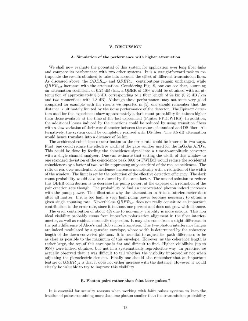
(4.1%) and QBERacc (1.0%) are essentially unchanged, as expected. On the other hand,QBERdet increased to 3%. These contributions sum up to 8.1%, again slightly above themeasured minimum value.One can see on Fig. 8 a graph showing the QBER as a function of the attenuation of
the link between Alice and Bob. It shows the experimental minimum (circles) and average(diamonds) values obtained with and without the spool connected. The solid line showssimulated values, with current InGaAs APD’s. The contributions QBERacc and QBERopt,independent on the attenuation , are represented by the dashed lines.
12
V. DISCUSSION
A. Simulation of the performance with higher attenuation
We shall now evaluate the potential of this system for application over long fiber linksand compare its performance with two other systems. It is a straightforward task to ex-trapolate the results obtained to take into account the effect of different transmission lines.As discussed above, the QBERopt and QBERacc contributions remain unchanged, whileQBERdet increases with the attenuation. Considering Fig. 8, one can see that, assumingan attenuation coefficient of 0.25 dB / km, a QBER of 10% would be obtained with an at-tenuation of approximately 8.5 dB, corresponding to a fiber length of 24 km (0.25 dB / kmand two connections with 1.3 dB). Although these performances may not seem very goodcompared for example with the results we reported in [5], one should remember that thedistance is ultimately limited by the noise performance of the detector. The Epitaxx detec-tors used for this experiment show approximately a dark count probability four times higherthan those available at the time of the last experiment (Fujitsu FPD5W1KS). In addition,the additional losses induced by the junctions could be reduced by using transition fiberswith a slow variation of their core diameter between the values of standard and DS-fiber. Al-ternatively, the system could be completely realized with DS-fiber. The 8.5 dB attenuationwould hence translate into a distance of 34 km.The accidental coincidences contribution to the error rate could be lowered in two ways.
First, one could reduce the effective width of the gate window used for the InGaAs APD’s.This could be done by feeding the coincidence signal into a time-to-amplitude converterwith a single channel analyzer. One can estimate that setting the width of this window toone standard deviation of the coincidence peak (800 ps FWHM) would reduce the accidentalcoincidences by a factor of two, while suppressing only one third of the real coincidences. Theratio of real over accidental coincidences increases monotically with a reduction of the widthof the window. The limit is set by the reduction of the effective detection efficiency. The darkcount probability would also be reduced by the same factor. The second solution to reducethis QBER contribution is to decrease the pump power, at the expense of a reduction of thepair creation rate though. The probability to find an uncorrelated photon indeed increaseswith the pump power. This illustrates why the attenuation in Alice’s interferometer doesafter all matter. If it is too high, a very high pump power becomes necessary to obtain agiven single counting rate. Nevertheless QBERacc does not really constitute an importantcontribution to the error rate, since it is about one percent and does not grow with distance.The error contribution of about 4% due to non-unity visibility is more serious. This non
ideal visibility probably stems from imperfect polarization alignment in the fiber interfer-ometer, as well as residual chromatic dispersion. It may also come from a slight difference inthe path difference of Alice’s and Bob’s interferometers. The two-photon interference fringesare indeed modulated by a gaussian envelope, whose width is determined by the coherencelength of the down-converted photons. It is essential to adjust the path differences to beas close as possible to the maximum of this envelope. However, as the coherence length israther large, the top of this envelope is flat and difficult to find. Higher visibilities (up to95%) were indeed obtained but not in a systematically reproducible way. In practice, weactually observed that it was difficult to tell whether the visibility improved or not whenadjusting the piezoelectric element. Finally one should also remember that an importantfeature of QBERopt is that it does not either increase with the distance. However, it wouldclearly be valuable to try to improve this visibility.
B. Photon pairs rather than faint laser pulses ?
It is essential for security reasons when working with faint pulses systems to keep thefraction of pulses containing more than one photon smaller than the transmission probability
13

TL · TB. If this is not the case, the spy could use the so-called photon number splittingattack to obtain substantial information about the key material exchanged (see [20–22] for adiscussion of this strategy). She could indeed measure the number of photons per pulse, andstop all those that do not contain more than one photon. In turn, when a pulse contains twoor more photons, she splits it and stores one photon, while she dispatches the other photonto Bob through a lossless medium. Finally, she waits until Alice and Bob reveal the basesthey used to perform her own measurements, and obtains full information. This potentialattack implies that µ must be reduced, when the distance is increased. It amplifies the effectof fiber attenuation on QBERdet, which limits transmission to even shorter distances.Our set-up using photon pairs is not vulnerable to this attack. Indeed, even in the case
where two (or more) photon pairs are created within a gate time of each other, the fact thatthe state preparation, amounting to the basis and bit value choices, is made in a passive wayensures that one photon is not correlated in any way with a photon belonging to another pair.However, for this to be true, Alice must treat cautiously double detections [23]. She cannotsimply discard these events, but must assign them a random value. This increases the errorrate, without revealing information to Eve. When observing two photons in the quantumchannel and a pulse in the classical one, Eve could otherwise deduce that their conjugatestook the same output port at Alice’s, yielding a single detection, and are thus correlated.In practice, because of limited detection efficiency, double detections are extremely rare.Like the experiment of Tittel [10], our experiment offers thus a superior level of security,which represents its main advantage over faint laser pulses systems. The two others QKDexperiments performed with photon pairs [11,12] used active basis switching. Two photonsof different pairs are thus invariably prepared in the same basis. Nevertheless the actual bitvalue is selected randomly. In this case, when two photon pairs are emitted simultaneously,Eve can obtain probabilistic information about the bit value.To summarize this security issue, we suggest to distinguish three levels. First, a system
could be immune to all attacks, including multiphoton splitting, like the one presented inthis article. In this case, the level of security is extremely high. Such a system resistsattacks with existing, as well as future technology. Its cost and complexity may howeverbe too high for real applications. Second, one can consider systems based on faint pulses.They are immune to existing technology, but would not always resist multiphoton splittingattacks. However, it is essential here to realize that, although in principle possible, suchan attack would be in practice incredibly difficult. A natural idea to realize a losslesschannel – one of the components necessary for such these attacks – is to use free-spacepropagation. However, attenuation in air at 1550 nm is higher than in fibers (0.64 dB / kmunder good visibility [24]). Moreover, it depends critically on the atmospheric conditions (inparticular humidity). Diffraction and turbulence induced beam wandering also reduce thetransmission. On the other hand, faint pulses systems offer the advantage to be reasonablyeasy to operate and automate. In addition, they could actually be ready for real applicationsquickly. Finally, one can look at classical public key cryptography, which is consideredto offer sufficient security, when implemented with suitable key length. In addition, it isconvenient to apply, as it does not require any dedicated channel, and has been in use formany years. It however suffers from a major disadvantage. Its security could indeed bejeopardized overnight by some theoretical advance. In this event, QKD with faint pulseswould constitute the only realistic replacement technology. In addition, when using publickey cryptography, it is essential to assess the level of computer power that will becomeavailable to a potential eavesdropper during the time the encrypted information bears someimportance. It is indeed also threatened by future developments, while both types of QKDsystems are only vulnerable to technology existing at the time of the key exchange. QKDwith faint pulses may well constitute a compromise between complexity and security.A second advantage is that, when Alice detects one photon of a pair, she knows that
a twin photon was also created. This means that we remove the vacuum component ofthe faint laser pulses. In principle the probability µ approaches then 1. The correct countprobability for a given value of the attenuation is increased and the contribution QBERdet
14

lowered. A certain QBER will be obtained after a longer distance. It is important to notethat this is beneficial only because detectors are imperfect and feature noise. If they did not,it would always be possible to compensate the lower count probability by a larger repetitionfrequency.
C. Comparison with previous QKD experiments
We can now compare the performance of the system presented in this paper with twoother set-ups. We first look at the “plug&play” QKD system presented in [5]. It featuresself alignment and highly stable operation, and was tested by our group over a 22 kmlong installed optical fiber in 1998. Our new system in principle allows distribution overa longer distance. If we take now into account the fact that our source yields a µ of only0.6, we see that the ratio of the detector contributions to the error rates of both systems isreduced to QBERP&P
det /QBERdet = 3/2, instead of 5/2 when setting µ to 1. This factorcorresponds to an attenuation of about 1.8 dB, which translates into 7 km of fiber at 1550nm. This difference is not really significant. In addition, the “Plug&Play” featured anexcellent QBERopt of 0.14%, and no errors by accidental coincidences. However, the mostimportant advantage of the system presented in this paper is clearly the fact that it relieson photon pairs and passive state preparation, benefitting thus from high security. It doesindeed not offer to Eve at all the possibility to exploit multi-photons pulses for her attack.We must however admit that the operation of the “plug&play” is definitely simpler thanour system, thanks to its self-alignment feature. This would also constitute an importantparameter when realizing a prototype to be used by non-physicists. The main difficulty inthe manipulation of our new system comes from the fact that two interferometers must bealigned and kept stable. The stability problem is of course also encountered with all theother conventional phase encoding QKD systems [2,3].We can also compare it with the system presented by Tittel et al. in [10], who were the first
ones to implement QKD with photon pairs beyond 1 µm. They used a pulsed pump laser,whose light passes through an interferometer, before impinging onto the non-linear crystaland generating photon pairs. The first measurement basis is implemented exactly like in thecontinuous pump system, presented in this paper. No phase change in the interferometersis required, since the second basis is implemented on non-interfering events. This impliesthat the factor qinterf has a value of 1, while the other parameters can in principle havethe same value as that of the continuous pump set-up. This yields a reduction of QBERdet
by a factor 2. On the other hand, the two detectors must be opened during three timewindows, because of the passive basis choice. The central window corresponds to the firstmeasurement basis using interfering events, while the two others correspond to the secondbasis (non-interfering events). In the system presented here, the detectors are opened onlytwice. This implies a QBERdet contribution 3
2times higher in the pulsed source system,
assuming identical detectors and transmission attenuation. Overall, this system features aQBERdet contribution 0.75 (= 3
2· 1
2) times lower. This factor can be translated into a gain
in distance of about 5 km. Finally, the fact that this pulsed source system requires alignmentand stabilization of three interferometers (Alice, Bob and the source) however constitutesan additional practical difficulty.
VI. CONCLUSION
In this article, we presented a detailed analysis of quantum key distribution with entan-gled states, discussing in particular the noise sources and practical difficulties associatedwith these systems. A QKD system exploiting photon pairs optimized for long distance op-eration was tested. We implemented an asymmetrical Franson type experiment for photonsentangled in energy-time and uses a key distribution protocol analogous to BB84. Passive
15

state preparation, realized by polarization multiplexing of the interferometers, offers supe-rior security. With Alice and Bob directly connected, a sifted bit sequence of 1.7 Mbits wasdistributed at a raw rate of 450 Hz, and exhibited a QBER of 5.9%. With an 8.45 km-longfiber between them, we distributed a sequence of 0.41 Mbits at a raw rate of 134 Hz, andwith an error rate of 8.6%. We also discussed the level of security offered by such a system.Finally, we compared the performance obtained with that of a faint pulse scheme, as well asan alternate one based on entangled photon pairs.
Acknowledgement 1 The Swiss FNRS and OFES as well as the European QuCom project(IST-1999-10033) have supported this work. The authors would also like to thank BrunoHuttner for stimulating discussions.
16

Line Attenuation Minimum Average Raw rate Duration Raw key Estimatedlength QBER QBER length net rate(meters) (dB) (Hz) (minutes) (bits) (Hz)
20 ≈ 0 4.7% 5.9% 450 63 1704118 1788450 4.7 6.6% 8.6% 133 51 407930 32
TABLE I. Summary of the performance obtained
17

FIG. 1. a) Franson type arrangement forgenerating non-local quantum correlations withphoton pairs entangled in energy time. b) Im-plemenation of the double measurement basiswith four interferometers.
FIG. 2. Asymmetric system for quantum keydistribution utilizing photon pairs.
FIG. 3. Schematic diagram of the photonpair source (HW: half-wave plate, L: lens,P: dispersive prism, M: metallic mirror, DM:dichroic mirror, F: filter, SMF: single-modefiber)
FIG. 4. Schematic diagram of Alice’s inter-frometer (PCA: polarization controller, SMF:single-mode fibre, L: lens, TP: trombone prism,PBS: polarizing beamsplitter)
FIG. 5. Schematic diagram of Bob’s inter-ferometer (PBS: polarizing beamsplitter, FM:Faraday mirror, PC: polarization controllers,ABE: adjustable birefringent element, DSF: dis-persion shifted fiber).
0
200
400
600
800
1000
1200
0 200 400 600 800 1000 1200
Time [s]
Coi
ncid
ence
s (in
2 [s
])
Noi
se c
ount
s
FIG. 6. Typical two photons interferencevisibility measurement. Coincidences betweena Si-APD at Alice’s and an InGaAs-APD atBob’s.
18

0%
20%
40%
60%
80%
100%
0 2000 4000 6000 8000 10000Time [s]
QB
ER
0
100
200
300
400
500
600
Raw
key
rat
e [H
z]
QBER
Key rate
FIG. 7. Key distribution session. The verti-cal broken lines indicate the region used to cal-culate the average QBER. The acquisition timefor one data point was 2 seconds.
FIG. 8. Experimental values of QBERmin
(circles) and QBERaverage (crosses), and ex-trapolation of the QBER (continuous line). Thetwo contributions (QBERacc and QBERopt)that do not depend on the distance are alsoshown (broken lines).
[1] C. Bennett and G. Brassard, in Proc. ofIEEE Inter. Conf. on Computers, Systemsand Signal Processing, Bangalore, (IEEE,New York, 1984), p. 175 .
[2] P. Townsend, Optical Fiber Technology 4,345 (1998).
[3] R. Hughes, G. Morgan, and C. Peterson,Journal of Modern Optics 47, 533 (2000).
[4] J.-M. Merolla, Y. Mazurenko, J.-P.Goedgebuer, and W. Rhodes, Phys. Rev.Lett. 82, 1656 (1999).
[5] G. Ribordy, J.-D. Gautier, N. Gisin, O.Guinnard, and H. Zbinden, Journal ofModern Optics 47, 517 (2000).
[6] A. Ekert, Phys. Rev. Lett. 67, 661 (1991).[7] P. Tapster, J. Rarity, P. Owens, Phys. Rev.
Lett. 73, 1923 (1994).[8] W. Tittel, J. Brendel, H. Zbinden, and N.
Gisin, Phys. Rev. Lett. 81, 3563 (1998).[9] G. Weihs, T. Jennewein, C. Simon, H. We-
infurter, and A. Zeilinger, Phys. Rev. Lett.81, 5039 (1998).
[10] W. Tittel, J. Brendel, H. Zbinden, and N.Gisin, Phys. Rev. Lett 84, 4737 (2000).
[11] D. Naik, C. Peterson, A. White, A.Berglund, and P. Kwiat, Phys. Rev. Lett.84, 4733 (2000).
[12] T. Jennewein, C. Simon, G. Weihs, H. We-infurter, and A. Zeilinger, Phys. Rev. Lett.84, 4729 (2000).
[13] J. D. Franson, Phys. Rev. Lett. 62, 2205(1989).
[14] A. Ekert, J. Rarity, P. Tapster, and M.Palma, Phys. Rev. Lett. 69, 1293 (1992).
[15] C. Bennett, F. Bessette, G. Brassard, L.Salvail, and J. Smolin, J. Cryptology 5, 3(1992)
[16] Special issue of IEEE J. Lightwave Tech.12, edited by D. Hall, 1705 (1994).
[17] N. Lutkenhaus, Phys. Rev. A 61, 052304(1999).
[18] P. Townsend, Electron. Lett. 30, 809(1994).
[19] G. Ribordy, J.-D. Gautier, H. Zbinden, andN. Gisin, Appl. Opt. 37, 2272 (1998).
[20] B. Huttner, N. Imoto, N. Gisin, and T.Mor, Phys. Rev. A 51, 1863 (1995).
[21] H. Yuen, Quantum Semiclassic. Opt. 8, 939(1996).
[22] G. Brassard, N. Lutkenhaus, T. Mor, andB. Sanders, Phys. Rev. Lett 85, 1330(2000).
[23] N. Lutkenhaus, Phys. Rev. A 59, 3301(1999).
[24] H. Gebbie, W. Harding, C. Hilsum, A.Pryce, and V. Roberts, Proc. Roy. Soc. A206, 87 (1951).
19