arXiv:hep-ex/0011066v1 20 Nov 2000 · arxiv:hep-ex/0011066v1 20 nov 2000 uf-ihepa 00-01 exclusive...
140
arXiv:hep-ex/0011066v1 20 Nov 2000 UF-IHEPA 00-01 EXCLUSIVE MEASUREMENTS IN B → D ∗ N ¯ NX BY ANTONIO I. RUBIERA A DISSERTATION PRESENTED TO THE GRADUATE SCHOOL OF THE UNIVERSITY OF FLORIDA IN PARTIAL FULFILLMENT OF THE REQUIREMENTS FOR THE DEGREE OF DOCTOR OF PHILOSOPHY UNIVERSITY OF FLORIDA 2000
Transcript of arXiv:hep-ex/0011066v1 20 Nov 2000 · arxiv:hep-ex/0011066v1 20 nov 2000 uf-ihepa 00-01 exclusive...

arX
iv:h
ep-e
x/00
1106
6v1
20
Nov
200
0
UF-IHEPA 00-01
EXCLUSIVE MEASUREMENTS IN B → D∗NNX
BY
ANTONIO I. RUBIERA
A DISSERTATION PRESENTED TO THE GRADUATE SCHOOLOF THE UNIVERSITY OF FLORIDA IN PARTIAL FULFILLMENT
OF THE REQUIREMENTS FOR THE DEGREE OFDOCTOR OF PHILOSOPHY
UNIVERSITY OF FLORIDA
2000

ACKNOWLEDGMENTS
If the pursuit of an undergraduate degree is comparable to a 500-meter race,
the pursuit of a doctorate is more like a marathon. Many people have been instru-
mental to me finishing this marathon.
The idea for this analysis came from my advisor, John Yelton, who played a
principal role in its success. His patience and wisdom have been instrumental in
my development as a scientist. Paul Avery offered helpful criticisms along the way
which helped me improve my delivery of the results. I would also like to thank
the University of Florida faculty members who have been most helpful to me, for
the courses they taught, and the professional guidance they willingly volunteered:
Pierre Ramond, Charles Thorn, Zongan Qiu, and Bernard Whiting. While at
Cornell I was guided and helped by David Besson, Brian Helstley, David Jaffe
and Andy Foland. Many of the suggestions that have improved the quality of this
analysis came from these colleagues. My fellow graduate students in the CLEO
Florida group, Jiu Zheng and Craig Prescott, were patient in their guidance. Andy
Foland and Craig Prescott proved to me that brilliance can be achieved without
arrogance.
The long and tortuous road to the finish line would not be possible without
the unflinching support of my family: my grandfather and grandmother, my father
and mother. I fail to find words that accurately describe how deeply I feel my debt
to them. Neither my grandfather nor my mother lived to see their seeds bear fruit.
Their positive influence is sorely missed.
The lunch CLEO software elite endured my opinions: Andreas Warburton,
David Urner, Peter Gaidarev, Martin Lohner, Chris Jones and Adam Lyon. The
ii

Chapter House gang, Rahida, Samina, Basit and Mike Marsh, made my Friday
nights during the nine months of Ithaca summer considerably more enjoyable than
they would have been otherwise. I thank the deplorable upstate New York weather
for forcing me to work harder. The Chapter House gang also endured my opinions,
but with the added advantage of a few beers. Herbert, Pia, and baby Gabriel
offered me company off-CLEO while I lived in Ithaca. Lauren Hsu and Antonella
Cipollone allowed me to pass on some of my analysis experience. I thank Jean
Duboscq and Bonnie Valant-Spaight, and Stefan Anderson.
I have been fortunate to be graced with friends who have offered me their
company and their understanding during the bad times and loads of fun during
the good times: From Cornell EE, Wolfgang Hofman and Jason Reed; From UF,
Steve Thomas (who shared with me his deep insights into French culture), Dawn
Shuler, Mike (DR) Jones, Richard Pietri, Richard Haas and Ilsa Webeck; From
Miami High/Miami/Cornell, Christine Sobilo, Luis (Kike) Ramos, George and
Oscar Hernandez, Armando Garcia de la Torre, Elizabeth San Martin, Elizabeth
Padron, Mario and Blanca Berrios, Jimmy Windsor, Jimmy Windsor Jr, Tiburon,
and others who I may have unwittingly forgotten. Barbara Tuchman and Henry
Kissinger provided invaluable reading material. Madonna, Depeche Mode, and the
Orb provided great music.
I hope a new generation of graduate students is able to profit from this analysis,
and thank the CLEO collaboration for all its support.
iii

TABLE OF CONTENTS
ACKNOWLEDGMENTS . . . . . . . . . . . . . . . . . . . . . . ii
ABSTRACT . . . . . . . . . . . . . . . . . . . . . . . . . . . . vii
CHAPTERS
1 INTRODUCTION . . . . . . . . . . . . . . . . . . . . . . . . 11.1 Matter . . . . . . . . . . . . . . . . . . . . . . . . . . . . . . . . . . 2
1.1.1 Hadrons . . . . . . . . . . . . . . . . . . . . . . . . . . . . . 21.1.2 Leptons. . . . . . . . . . . . . . . . . . . . . . . . . . . . . . 41.1.3 Gauge Bosons . . . . . . . . . . . . . . . . . . . . . . . . . . 51.1.4 Spin and Statistics . . . . . . . . . . . . . . . . . . . . . . . 61.1.5 The CKM Matrix . . . . . . . . . . . . . . . . . . . . . . . . 61.1.6 Symmetries . . . . . . . . . . . . . . . . . . . . . . . . . . . 7
1.2 Decays . . . . . . . . . . . . . . . . . . . . . . . . . . . . . . . . . . 81.2.1 Weak Decays . . . . . . . . . . . . . . . . . . . . . . . . . . 81.2.2 Strong Decays . . . . . . . . . . . . . . . . . . . . . . . . . . 10
1.3 B Meson Decays . . . . . . . . . . . . . . . . . . . . . . . . . . . . 131.3.1 Quantum Chromodynamics . . . . . . . . . . . . . . . . . . 161.3.2 Heavy Quark Effective Theory . . . . . . . . . . . . . . . . . 171.3.3 Semileptonic Decays to Mesons . . . . . . . . . . . . . . . . 191.3.4 Hadronic Decays to Mesons . . . . . . . . . . . . . . . . . . 19
1.4 B → Baryons . . . . . . . . . . . . . . . . . . . . . . . . . . . . . . 211.4.1 Results to Date . . . . . . . . . . . . . . . . . . . . . . . . . 211.4.2 The Argument for B → [D]NNX modes . . . . . . . . . . . 221.4.3 Thesis Overview . . . . . . . . . . . . . . . . . . . . . . . . 23
2 CLEO II DETECTOR . . . . . . . . . . . . . . . . . . . . . . 282.1 Sub-detector Components . . . . . . . . . . . . . . . . . . . . . . . 302.2 Tracking System . . . . . . . . . . . . . . . . . . . . . . . . . . . . 33
2.2.1 PTL Detector . . . . . . . . . . . . . . . . . . . . . . . . . . 342.2.2 SVX Detector . . . . . . . . . . . . . . . . . . . . . . . . . . 342.2.3 Drift Chamber . . . . . . . . . . . . . . . . . . . . . . . . . 342.2.4 Momentum and Angular Resolution . . . . . . . . . . . . . . 352.2.5 dE/dx Measurements . . . . . . . . . . . . . . . . . . . . . . 36
iv

2.2.6 Time-of-Flight Measurements . . . . . . . . . . . . . . . . . 402.3 Electromagnetic Calorimeter . . . . . . . . . . . . . . . . . . . . . . 40
2.3.1 Dimensions . . . . . . . . . . . . . . . . . . . . . . . . . . . 422.3.2 Clustering . . . . . . . . . . . . . . . . . . . . . . . . . . . . 43
2.4 Muon Detector . . . . . . . . . . . . . . . . . . . . . . . . . . . . . 46
3 PARTICLE SELECTION . . . . . . . . . . . . . . . . . . . . . 473.1 Data Sample . . . . . . . . . . . . . . . . . . . . . . . . . . . . . . . 483.2 Monte Carlo Sample . . . . . . . . . . . . . . . . . . . . . . . . . . 483.3 Track Selection . . . . . . . . . . . . . . . . . . . . . . . . . . . . . 49
3.3.1 Fitting Algorithm . . . . . . . . . . . . . . . . . . . . . . . . 493.3.2 Drift Chamber Track Variables . . . . . . . . . . . . . . . . 503.3.3 The TRKMNG Package . . . . . . . . . . . . . . . . . . . . 51
3.4 Particle Separation . . . . . . . . . . . . . . . . . . . . . . . . . . . 513.5 π0 Reconstruction . . . . . . . . . . . . . . . . . . . . . . . . . . . . 533.6 D∗ Reconstruction . . . . . . . . . . . . . . . . . . . . . . . . . . . 54
3.6.1 The KNLIB Fitting Package . . . . . . . . . . . . . . . . . . 543.6.2 Fit Optimization . . . . . . . . . . . . . . . . . . . . . . . . 553.6.3 Comparison with B → D∗X . . . . . . . . . . . . . . . . . . 63
3.7 Antineutron Showers . . . . . . . . . . . . . . . . . . . . . . . . . . 653.7.1 Shower Parameters . . . . . . . . . . . . . . . . . . . . . . . 673.7.2 Antiproton Showers in Data . . . . . . . . . . . . . . . . . . 683.7.3 Antineutron Selection Criteria . . . . . . . . . . . . . . . . . 703.7.4 Antineutron Backgrounds . . . . . . . . . . . . . . . . . . . 73
4 MEASUREMENT OF B0 → D∗−PPπ+ . . . . . . . . . . . . . . 754.1 Monte Carlo Reliability . . . . . . . . . . . . . . . . . . . . . . . . . 754.2 Reconstruction Procedure . . . . . . . . . . . . . . . . . . . . . . . 764.3 Monte Carlo Study . . . . . . . . . . . . . . . . . . . . . . . . . . . 774.4 Results in Data . . . . . . . . . . . . . . . . . . . . . . . . . . . . . 794.5 Resonant Substructure . . . . . . . . . . . . . . . . . . . . . . . . . 89
4.5.1 Two-body Decay and Possible Strong Resonances . . . . . . 894.5.2 ∆ Baryon Contributions in the Form of B0 → D∗−p∆++ and
B0 → D∗−p∆0 . . . . . . . . . . . . . . . . . . . . . . . . . 904.6 Backgrounds . . . . . . . . . . . . . . . . . . . . . . . . . . . . . . . 914.7 Systematic Uncertainties . . . . . . . . . . . . . . . . . . . . . . . . 93
5 MEASUREMENT OF B0 → D∗−PN . . . . . . . . . . . . . . . 945.1 Reconstruction Procedure . . . . . . . . . . . . . . . . . . . . . . . 955.2 D+
s → p n in Monte Carlo . . . . . . . . . . . . . . . . . . . . . . . 96
v

5.3 Results in Data . . . . . . . . . . . . . . . . . . . . . . . . . . . . . 1015.4 D+
s → p n in Data . . . . . . . . . . . . . . . . . . . . . . . . . . . 1045.5 B(B0→ D∗− p n ) Measurements. . . . . . . . . . . . . . . . . . . . 1065.6 Correction Factor . . . . . . . . . . . . . . . . . . . . . . . . . . . . 1095.7 Use of a Λ Sample . . . . . . . . . . . . . . . . . . . . . . . . . . . 110
5.7.1 Backgrounds in Signal and Generic Monte Carlo . . . . . . . 1145.8 Antineutron Directional Cosine Resolution . . . . . . . . . . . . . . 1155.9 B0 → D∗+pn. . . . . . . . . . . . . . . . . . . . . . . . . . . . . . 1165.10 Systematic Uncertainties . . . . . . . . . . . . . . . . . . . . . . . . 118
6 CONCLUSION . . . . . . . . . . . . . . . . . . . . . . . . 1196.1 B → Baryons phenomenology . . . . . . . . . . . . . . . . . . . . . 1206.2 Possible Future B → Baryons Modes at CLEO . . . . . . . . . . . . 1216.3 Significance of Results . . . . . . . . . . . . . . . . . . . . . . . . . 121
REFERENCES . . . . . . . . . . . . . . . . . . . . . . . . . . 123
BIOGRAPHICAL SKETCH . . . . . . . . . . . . . . . . . . . . 126
vi

Abstract of Dissertation Presented to the Graduate Schoolof the University of Florida in Partial Fulfillment of theRequirements for the Degree of Doctor of Philosophy
UF-IHEPA 00-01
EXCLUSIVE MEASUREMENTS IN B → D∗NNX
By
Antonio I. Rubiera
August 2000
Chairman: J. YeltonMajor Department: Physics
We report the first observation of exclusive decays of the type B → D∗NNX ,
where N is a nucleon. Using a sample of 9.7 × 10⁶ BB pairs collected with the
CLEO detector operating at the Cornell Electron Storage Ring, we measure the
branching fractions B (B0 → D∗−ppπ+) = (6.5+1.3−1.2 ± 1.0) × 10−4, and B(B0→
D∗−pn ) = (14.5+3.4−3.0 ± 2.7) × 10−4. The charge conjugate process is implied in
the reconstruction of B0→ D∗− p p π+. However, in the reconstruction of B0→
D∗− p n, only the mode with the antineutron is used in our measurement because
neutrons do not have a distinctive annihilation signature.
Antineutrons are identified by their annihilation in the CsI electromagnetic
calorimeter. Since we are unable to isolate a sample of antineutrons in data, we
use antiproton annihilation showers in a Λ → pπ+ sample to define the antineu-
tron selection criteria. We find a discrepancy for antiproton annihilation showers
between the Monte Carlo and data, which we assume affects antineutrons as well.
We increase the raw yield for B0→ D∗− p n by 21% to correct for this discrepancy.
vii

The possible contributions from B0 → D∗− D+s with D+
s → p n and B0 → D∗−
D∗+s with D∗+
s → D+s γ and D+
s → p n are eliminated from the analysis by rejecting
events with 1.91 GeV < Mp+n < 2.04 GeV for a loss of 9% in the reconstruction
efficiency. We fail to find evidence for the decay D+s → p n.
We search for possible contributions to the resonant substructure of B0→ D∗−
p n and B0→ D∗− p p π+ due to a heavy charmed baryon decaying strongly to p
D∗− for B0→ D∗− p p π+ and n D∗− for B0→ D∗− p n, as well as a resonance of
the virtual W decaying to ppπ+. We also study the possible effect of feed-down ∆
baryon contributions to the background for both modes, as well as the B0→ D∗−
p p π+ signal. No conclusive evidence is found for a measurable contribution from
the aforementioned contributions to the resonant substructure.
Antineutrons are used for the first time in the exclusive reconstruction of a
B meson. By finding conclusive evidence for the existence of decay modes of the
type B → DNNX , we challenge the assumption that the B → Baryons rate is
dominated by decays to charmed baryons.
viii

List of Figures
1.1 A Feynman diagram for neutron beta decay in Fermi Weak Theory 91.2 A Feynman diagram for neutron beta decay in the Standard Model 91.3 A Feynman diagram for D∗ → D0πsoft . . . . . . . . . . . . . . . . 111.4 A second Feynman diagram for D∗ → D0πsoft . . . . . . . . . . . . 121.5 A color-allowed Feynman diagram for B− → D0π− for one quark
color . . . . . . . . . . . . . . . . . . . . . . . . . . . . . . . . . . . 141.6 A color-suppressed Feynman diagram for B− → D0π− for one quark
color . . . . . . . . . . . . . . . . . . . . . . . . . . . . . . . . . . . 151.7 A Feynman diagram for B− → Λc
+pπ−. . . . . . . . . . . . . . . . 221.8 Two Feynman diagrams for B0→ D∗− p n . . . . . . . . . . . . . 261.9 A Feynman diagram for B0→ D∗− p p π+ . . . . . . . . . . . . . 27
2.1 Cross section into hadrons from the collision of e+e− beams at CESRas measured by the CLEO II detector in the energy range 9.44 GeVto 10.62 GeV . . . . . . . . . . . . . . . . . . . . . . . . . . . . . . 29
2.2 Front view of the CLEO II detector . . . . . . . . . . . . . . . . . 312.3 Side view of the CLEO II detector . . . . . . . . . . . . . . . . . . 322.4 dE/dx vs. track momentum . . . . . . . . . . . . . . . . . . . . . . 382.5 Main drift chamber (DR) wire arrangement . . . . . . . . . . . . . 392.6 Time-of-Flight vs. track momentum . . . . . . . . . . . . . . . . . 412.7 Layout of CLEO II detector showing barrel and endcap calorimeter
sections . . . . . . . . . . . . . . . . . . . . . . . . . . . . . . . . . 42
3.1 mD∗-mD0 in GeV for B → D∗X with D0→K+π− in CLEO II . . . 573.2 mD∗-mD0 in GeV for B → D∗X with D0→K+π− in CLEO II.5 . . 583.3 mD∗-mD0 in GeV for B → D∗X with D0→K+π−π0 in CLEO II . . 593.4 mD∗-mD0 in GeV for B → D∗X with D0→K+π−π0 in CLEO II.5 . 603.5 mD∗-mD0 in GeV for B → D∗X with D0→K+π−π+π− in CLEO II 613.6 mD∗-mD0 in GeV for B → D∗X with D0→K+π−π+π− in CLEO II.5 623.7 Emain vs. PQCD for protons and antiprotons in CLEO II . . . . . 703.8 Emain vs. PQCD for protons and antiprotons in CLEO II . . . . . 713.9 Emain in GeV without proton requirement for n’s, γ’s from π0’s, and
KL’s . . . . . . . . . . . . . . . . . . . . . . . . . . . . . . . . . . . 743.10 Emain in GeV with proton requirement for n’s, γ’s from π0’s, and
KL’s . . . . . . . . . . . . . . . . . . . . . . . . . . . . . . . . . . . 74
ix

4.1 ∆E vs MBC distribution for B0→ D∗− p p π+ in CLEO II ONresonance data. . . . . . . . . . . . . . . . . . . . . . . . . . . . . . 80
4.2 ∆E vs MBC distribution for B0→ D∗− p p π+ in CLEO II.5 ONresonance data . . . . . . . . . . . . . . . . . . . . . . . . . . . . . 81
4.3 MBC (in GeV) for B0→ D∗− p p π+ in CLEO II . . . . . . . . . . 824.4 MBC (in GeV) for B0→ D∗− p p π+ in CLEO II.5. . . . . . . . . 834.5 MBC for B0→ D∗− p p π+ in data . . . . . . . . . . . . . . . . . . 864.6 ∆E (in GeV) for B0→ D∗− p p π+ in CLEO II/II.5 data . . . . . 874.7 πs from D∗ momentum for B0→ D∗− p p π+ in data and Monte
Carlo . . . . . . . . . . . . . . . . . . . . . . . . . . . . . . . . . . 884.8 MBC in data and generic Monte Carlo for B0→ D∗− p p π+ (in GeV) 92
5.1 A Feynman diagram for D+s → p n . . . . . . . . . . . . . . . . . . 96
5.2 Mp+n in GeV. B0 → D+s D∗− with D+
s → p n . . . . . . . . . . . . 975.3 Mp+n (in GeV) from a reconstruction of B0→ D∗− p n in a signal
Monte Carlo B0 → D∗+s D∗− with D+
s → p n . . . . . . . . . . . . 985.4 (white) is B0 → D+
s D∗− with D+s → p n. (dashed) is B0 → D∗+
s
D∗− with D+s → p n. Mp+n (in GeV) . . . . . . . . . . . . . . . . 99
5.5 (white) is B0 → D+s D∗− with D+
s → p n. (dashed) is B0 → D∗+s
D∗− with D+s → p n. mB0 (in GeV) . . . . . . . . . . . . . . . . . 99
5.6 (white) is inclusive of all contributions. (dashed) is after exclusionof both D+
s → p n contributions . . . . . . . . . . . . . . . . . . . 1015.7 (white) is ON resonance, (solid) is OFF resonance . . . . . . . . . 1025.8 MB0 for B0→ D∗− p n in CLEO II ON resonance data . . . . . . 1035.9 MB0 for B0→ D∗− p n in CLEO II.5 ON resonance data . . . . . 1035.10 Mp+n for B0→ D∗− p n (in GeV) in CLEO II/II.5 . . . . . . . . . 1045.11 Mp+n vs. mB0 (both in GeV) . . . . . . . . . . . . . . . . . . . . . 1055.12 Inclusive mB0 in data for B0→ D∗− p n (in GeV) . . . . . . . . . 1065.13 mB0 in data for B0→ D∗− p n in GeV excluding both D+
s → p ncontributions . . . . . . . . . . . . . . . . . . . . . . . . . . . . . . 107
5.14 Antineutron momentum distribution (in GeV) . . . . . . . . . . . . 1125.15 mB0 in GeV for B0→ D∗− p n selection criteria applied to selected
signal Monte Carlo background modes . . . . . . . . . . . . . . . . 1145.16 mB0 for B0→ D∗− p n in GeV. (white) is data, (solid) is generic MC 1155.17 Emain (in GeV) for neutrons and antineutrons in B0→ D∗− p n
signal Monte Carlo . . . . . . . . . . . . . . . . . . . . . . . . . . . 117
x

List of Tables
1.1 Quark families . . . . . . . . . . . . . . . . . . . . . . . . . . . . . 31.2 Anti-quark families . . . . . . . . . . . . . . . . . . . . . . . . . . . 31.3 Estimated quark masses . . . . . . . . . . . . . . . . . . . . . . . . 31.4 Selected meson masses . . . . . . . . . . . . . . . . . . . . . . . . . 41.5 Selected baryon masses . . . . . . . . . . . . . . . . . . . . . . . . 41.6 Lepton masses . . . . . . . . . . . . . . . . . . . . . . . . . . . . . 51.7 Some characteristics of bosons . . . . . . . . . . . . . . . . . . . . 51.8 Some B meson decay mechanisms . . . . . . . . . . . . . . . . . . . 131.9 Representative B → Baryons decay mechanisms . . . . . . . . . . . 21
2.1 Some e+e− annihilation final states . . . . . . . . . . . . . . . . . . 302.2 Vertex detector and drift chamber parameters . . . . . . . . . . . . 352.3 Drift chamber resolution . . . . . . . . . . . . . . . . . . . . . . . . 352.4 Momentum resolution (δpt) for the CLEO II data at selected values
of pt . . . . . . . . . . . . . . . . . . . . . . . . . . . . . . . . . . . 362.5 Radiation lengths of material before barrel section of the calorimeter 432.6 Energy and angle resolutions for a photon in the barrel at two values
of cluster energy . . . . . . . . . . . . . . . . . . . . . . . . . . . . 45
3.1 The CLEO data . . . . . . . . . . . . . . . . . . . . . . . . . . . . 483.2 Particle identification criteria . . . . . . . . . . . . . . . . . . . . . 523.3 mD0 and mD∗-mD0 double Gaussian data cuts . . . . . . . . . . . . 633.4 D∗ yield: D0→K+π− . . . . . . . . . . . . . . . . . . . . . . . . . 643.5 D∗ yield: D0→K+π−π0 . . . . . . . . . . . . . . . . . . . . . . . . 653.6 D∗ yield: D0→K+π−π+π− . . . . . . . . . . . . . . . . . . . . . . 653.7 Shower types and energy measured in calorimeter . . . . . . . . . . 663.8 Antineutron shower selection criteria. . . . . . . . . . . . . . . . . 713.9 Shower population in a generic BB Monte Carlo sample without
proton requirement . . . . . . . . . . . . . . . . . . . . . . . . . . . 723.10 Shower population in a generic BB Monte Carlo sample with proton
requirement . . . . . . . . . . . . . . . . . . . . . . . . . . . . . . . 72
4.1 ∆E fit results for B0→ D∗− p p π+ signal MC in CLEO II . . . . 784.2 ∆E fit results for B0→ D∗− p p π+ signal MC in CLEO II.5 . . . 784.3 MBC distribution fit results for B0→ D∗− p p π+ signal MC in
CLEO II . . . . . . . . . . . . . . . . . . . . . . . . . . . . . . . . 78
xi

4.4 MBC distribution fit results for B0→ D∗− p p π+ signal MC inCLEO II.5 . . . . . . . . . . . . . . . . . . . . . . . . . . . . . . . 79
4.5 Results in the CLEO II/II.5 data of various fits to MBC for B0→D∗− p p π+ . . . . . . . . . . . . . . . . . . . . . . . . . . . . . . 84
4.6 B0→ D∗− p p π+ : number of events found per mode . . . . . . . . 854.7 % composition of generated (phase space MC) and events recon-
structed (data) of Mpπ+ and Mpπ+ . . . . . . . . . . . . . . . . . . 904.8 Estimate of systematic uncertainties (in %) for B0→ D∗− p p π+ . 93
5.1 Antineutron shower selection criteria. . . . . . . . . . . . . . . . . 945.2 B0→ D∗− p n signal MC ǫMC ’s and widths in CLEO II. . . . . . . 1005.3 B0→ D∗− p n signal MC ǫMC ’s and widths in CLEO II.5 . . . . . 1005.4 Measurements of B0→ D∗− p n branching fractions . . . . . . . . 1075.5 Results of various fits to mB0 for B0→ D∗− p n with or without
the D+s → p n contributions . . . . . . . . . . . . . . . . . . . . . . 108
5.6 Λ selection criteria . . . . . . . . . . . . . . . . . . . . . . . . . . . 1105.7 Λ double Gaussian fixed parameters . . . . . . . . . . . . . . . . . 1105.8 ǫannihilation: (%) of match 1 or 2 antiprotons in Λ’s passing annihi-
lation shower selection cuts for six momentum spectra . . . . . . . 1115.9 Correction Factor (C.F.) as a function of pproton and % of antineu-
trons found in signal Monte Carlo for each momentum range inCLEO II/II.5 . . . . . . . . . . . . . . . . . . . . . . . . . . . . . . 113
5.10 Neutron shower selection criteria . . . . . . . . . . . . . . . . . . . 1165.11 Estimate of systematic uncertainties (in %) for B0→ D∗− p n . . . 118
6.1 Exclusive measurements in B → Baryons to date . . . . . . . . . . 119
xii

CHAPTER 1INTRODUCTION
The study of the elementary particles at a wide range of interaction energies
has occupied scientists since the discovery of the electron in 1896 [1]. Particle
physics has evolved from a field involved in the discovery of new particles to one
devoted to their systematic study. A logical structure, currently explained by the
Standard Model of elementary particles [2, 3, 4], has been unveiled.
The Standard Model, however, offers an incomplete picture of some experi-
mental high energy physics results. The results we describe are amongst these.
Despite some weaknesses, the Standard Model has withstood intense experimental
scrutiny, and while some of the equations are currently not calculable, evidence
has not been found for physics beyond the Standard Model. Particles acquire their
masses in the Standard Model via the Higgs mechanism, that requires the existence
of a massive gauge boson, the Higgs boson, that has yet to be found.
We first introduce particle physics phenomenology -particles and their decays,
which is the information most often used by the practitioner of experimental high
energy physics. A discussion of the current status of B physics phenomenology
follows. Finally, we review B → Baryons previous to our results, concluding with
an overview of our work and its significance.
1

2
1.1 Matter
Matter is composed of three types of indivisible constituents: leptons, gauge
bosons, and quarks. Leptons and gauge bosons are found individually in Na-
ture. Quarks combine in two types of arrangements to form hadrons. The first
arrangement is of the form quark-antiquark, and is called a meson. The second
arrangement, three quarks, is called a baryon. Mesons and baryons, collectively
known as hadrons, comprise all the known forms of matter consisting of quarks.
Hadronic matter is said to be colorless. A color is assigned to each quark in a
meson or a baryon. The three quarks in a baryon each have a different color−red,
green, blue− and the combination of all three colors yields a colorless hadron. The
quark and the antiquark in a meson form a color-anticolor pair (e.g. qblueqblue).
1.1.1 Hadrons
There are three families of quarks, each consisting of two types of quark: an
up-type quark, with electromagnetic charges +2/3 that of the electron, or (+2/3)
qe, and a down-type quark, with (-1/3) qe. Every type of quark is called a flavor
of quark.
The first and lightest family consists of the up (u) and down (d) quarks. The
next family, with heavier quarks, is the charm (c) and strange (s) family. Even
heavier still is the third family: the top (t) and bottom (b) quarks. All are shown
in Table 1.1.
For every matter constituent there is an anti-matter constituent with opposite
electromagnetic charge and equal mass, as shown in Table 1.2.

3
Table 1.1: Quark families
up-type (+2/3) qe up: u charm: c top: tdown-type (-1/3) qe down: d strange: s bottom: b
Table 1.2: Anti-quark families
up-type (-2/3) qe u c tdown-type (+1/3) qe d s b
Quarks are not found individually in Nature. Their masses can be estimated
by the mass spectrum of mesons and baryons that has been measured to date.
In Table 1.3 we show current best estimates of the lower and upper limits for
quark masses. The estimated masses for quarks are useful in current Standard
Model calculations. However, the quark mass estimates have large uncertainties,
especially in the case of the up and down quarks. The values quoted in this Table
and the next values quoted in this section are from the 1998 Review of particle
physics [5]. The mass of the top quark mt = 173.8± 5.2 GeV.
Table 1.3: Estimated quark masses
Quark Low mass High massu 1.5 MeV 5 MeVd 3 MeV 9 MeVs 60 MeV 170 MeVc 1.1 GeV 1.4 GeVb 4.1 GeV 4.4 GeV
The proton, for example, has the quark content (uud), and one of the pions,
the π+, has the quark content (ud). Each type of quark is considered a distinct

4
flavor. The group of mesons containing a charm quark and a light antiquark (one
of s, u, d) is called the charm mesons.
Meson and baryon masses are known to varying degrees of accuracy, as shown
in Table 1.4 for selected mesons, and Table 1.5 for selected baryons.
Table 1.4: Selected meson masses
Meson Quark content Massπ± ud 139.56995± 0.00035 MeVK± su 493.677± 0.016 MeVD0 cu 1864.6± 0.5 MeVB0 bd 5279.2± 1.8 MeV
Table 1.5: Selected baryon masses
Meson Quark content Massproton uud 938.27231± 0.00028 MeV
Λ sud 1115.683± 0.006 MeVΛc cud 2284.9± 0.6 MeVΛb bud 5624± 9 MeV
1.1.2 Leptons.
The leptons, the e, the µ, and the τ , are fundamental particles. Each can be
produced with an accompanying neutrino, νl, with l = e, µ, or τ . Neutrino physics
in the near future will yield a better understanding than is currently available.
Neutrinos have been thought to be massless and not to mix (that is, each neutrino
flavor was thought only to interact with its lepton partner). The recent observation
of neutrino mixing, however, implies that neutrinos have mass [6]. Unlike quarks,

5
leptons are observed as single particles with well-measured masses. In Table 1.6
we show the current mass measurements. Large differences in masses are found
between the electron, the muon, and the tau.
Table 1.6: Lepton masses
Lepton Masselectron: e± 0.51099907± 0.00000015 MeVmuon: µ± 105.658389± 0.000034 MeVtau: τ± 1777.05+0.29
−0.26 GeV
Helicity is the orientation of a particle’s momentum vector in respect to its
spin. Helicity can be right-handed or left-handed for all fermions except neutrinos,
which are only left-handed. Antineutrinos, likewise, are only right-handed.
1.1.3 Gauge Bosons
The mediators of the physical forces, the particles that allow decays to take
place, are called gauge bosons. In Table 1.7 we outline their masses and the
types of interaction that each mediates. l = e, µ, τ , u=up-type quark(u, c, t), and
d=down-type quark(d, s, b).
Table 1.7: Some characteristics of bosons
Boson Force Mass Decaysphoton electromagnetic massless γ → l+l−
gluons strong massless g → qqW± weak 80.41± 0.10 GeV W+ → l+νl, udZ0 weak 91.187± 0.007 GeV W+ → l+l−, νν, q+q−

6
1.1.4 Spin and Statistics
Matter is also characterized by the statistics obeyed. Leptons and quarks are
fermions, obeying Fermi statistics, an example of which is the Pauli exclusion
principle for electrons occupying the same shell in an atom. The spin of leptons
and quarks is (±1
2). Bosons obey Bose statistics, which allow an infinite number of
particles to occupy the same energy state. Bosons have integral spin (0, ±1). The
different relative alignments of the spins of the individual quarks, together with
the addition of angular momentum, results in a large number of possible states.
1.1.5 The CKM Matrix
The interactions of quarks from different flavor families are suppressed with
respect to those within the same family. In order to correct for this discrepancy,
the characteristics of a given decay as prescribed by weak theory are adjusted using
the flavor mixing 3 × 3 unitary and complex matrix V , the Cabibbo-Kobayashi-
Maskawa matrix [5], which transforms the weak d, s, b quark states to the physically
measured d′
, s′
, b′
quark states, to arrive at a correct theoretical understanding of
a weak decay for all quark flavors:
VCKM =
Vud(0.9745− 0.9760) Vus(0.217− 0.224) Vub(0.004− 0.013)
Vcd(0.217− 0.224) Vcs(0.9737− 0.9753) Vcb(0.036− 0.042)
Vtd(0.004− 0.013) Vts(0.035− 0.042) Vtb(0.9991− 0.9994)
with

7
d′
s′
b′
= V
d
s
b
The diagonal elements of V are ≈ 1, implying that decays which involve these
CKMmatrix elements are Cabibbo-allowed, whereas all other decays, which involve
off diagonal elements, are Cabibbo-suppressed. For example, a b → cW−,W− →
cs decay has a much larger decay rate than a b→ cW−,W− → cd decay.
1.1.6 Symmetries
A particle and its antiparticle are said to be symmetric under CPT transfor-
mations, where C is charge conjugation, P is parity, and T is time reversal. The
inversion of parity acts like a mirror in the inversion of space coordinates. CPT
symmetry is valid for all forces.
A subset of this symmetry is CP. The product of a charge conjugation and a
parity inversion affect a particle the same as its antiparticle. When CP is violated,
a particle will prefer a different subset of decays than its antiparticle. Such is the
case for neutral kaons.The K0 and K0 states in weak theory are different from
the physically observed strong states, the KS, or K-short and the KL, or K-long,
each with its respective antiparticle. Short and long refer to the respective decay
lifetimes. Charge symmetry is obeyed implicitly in neutral kaon decay, but parity
is violated. CP violation is evident in the difference in decay rates of KS’s and
KL’s to final states of two and three pions, the former being even under parity,

8
and the latter odd under parity [7]. CP violation in B decays and will be the focus
of many studies in the near future.
1.2 Decays
All hadrons, except the proton and electron, are unstable and decay to lighter
hadrons, leptons, and bosons. The top quark decays well before the time required
to form hadrons (baryons or mesons). Therefore, the bottom group of baryons
(e.g. Λb, with quark content bud) and mesons (e.g. Bc, with quark content bc) is
the group of hadrons with the largest masses currently found in Nature.
1.2.1 Weak Decays
The b quark in the B meson decays via the weak interaction. The b quark
decay is often accompanied by the strong decays of soft gluons which allow for the
hadronization of a large number of final states. The Fermi Electroweak theory,
which aimed to explain neutron β decay, n → pe−νe, as shown by the Feynman
diagram Figure 1.1, introduced the neutrino to particle physics, serving as the
precursor of the Standard Model. A full theoretical understanding of this decay
was accomplished by the Standard Model, in which this decay is mediated by
the W vector boson, not present in the Fermi Electroweak theory. The decay
n→ pe−νe is correctly described as the quark level process d→W−u, followed by
W− → e−barνe, as shown by the Feynman diagram in Figure 1.2.

9
�
n
p
e
�
��
e
Figure 1.1: A Feynman diagram for neutron beta decay in Fermi Weak Theory
} { proton
neutron
Figure 1.2: A Feynman diagram for neutron beta decay in the Standard Model

10
Examples of weak semi-leptonic decays of mesons, analogous to neutron β
decay, are K+ → π0e+νe, D0 → K−e+νe, and B0 → D−e+νe. The weak semi-
leptonic decays of baryons follow a similar pattern. These decays are referred to as
semi-leptonic decays since the final products are a combination of a weak leptonic
decay and quark hadronization. Leptonic weak decays, in which the unstable
particle annihilates into an l+νl pair, examples of which are π+ → µ+νµ and
K+ → µ+νµ are the most theoretically well understood type of decays, as it lacks
any final state hadronization.
1.2.2 Strong Decays
The weak decays of the heavy (charm and bottom) quarks in mesons and
baryons often involve the secondary emission of strongly-interacting soft gluons.
While we understand the weak component of these decays using the Standard
Model, the strong component is not calculable.
The strong interaction hadronization process is not well understood theoreti-
cally when soft, or low momentum, gluons mediate the decay. The Standard Model
is based on perturbation expansions which rely on convergence. A process involv-
ing soft gluons yields equations that are no longer perturbatively convergent. This
stumbling block has prevented us from understanding many details of unstable
particle decay, particularly for the case of heavy hadrons, in which the large mass
available in the decay implies a very large number of possible final decay products
from an equally large number of soft gluons.
The D∗ meson, for example, which we reconstruct in this analysis, is a spin
1 meson that decays via the strong interaction. Two possible Feynman diagrams

11
for this decay are shown in Figures 1.3 and 1.4. Our ignorance about soft gluon
strong interactions forbids us from knowing the proportion of the total decay rate
due to any one diagram.
�
�
d
c
�
d
u
�u
c
g
Figure 1.3: A Feynman diagram for D∗ → D0πsoft

12
�
�
d
c
�
d
u
�u
c
g
Figure 1.4: A second Feynman diagram for D∗ → D0πsoft

13
1.3 B Meson Decays
The B meson, which is the topic of our study, can decay to a large number of
lighter particles by various mechanisms, some of which are detailed in Table 1.8.
The b → cW− type decays account for more than 95% of the B decays that are
possible in the Standard Model. The combined semileptonic decay rate for the
three lepton families is ≈ 25%, with hadronic decays accounting for almost all of
the remaining decay rate.
Table 1.8: Some B meson decay mechanisms
Quark-level mechanism Sample decay modeSemileptonic decay:b→ cW−,W− → l−νl B → Dl−νl
Hadronic decays:b→ cW−,W− → cs B → DDs
b → cW−,W− → ud B → Dπ
The W boson is colorless. Its decay to quarks constrains the color of both
quarks to cancel. The number of Feynman diagrams for a given B decay by the
color of the quarks. Whereas decays mediated by an external W boson allow for
any of the three possible colors (for example, the π− in B− → D0π−, as shown in
the Feynman diagram in Figure 1.5). Those in which theW boson decays internally
limit the color of all the quarks to be the same as that of the parent meson, as
shown in the Feynman diagram in Figure 1.6. The latter quality is referred to as
color suppression. Decays that only have an internal W boson-mediated diagram,
such as B0 → D0π0, are color-suppressed decays.

14
�
�u
green
b
green
�u
green
c
green
d
RGB
�u
RGB
W
�
Figure 1.5: A color-allowed Feynman diagram for B− → D0π− for one quark color

15
�
�u
green
b
green
�u
green
d
green
�u
green
c
green
W
�
Figure 1.6: A color-suppressed Feynman diagram for B− → D0π− for one quarkcolor

16
The decays b→ (c, u)W− are mediated by the W− vector boson, while decays
of type b → (s, d)γ and b → (s, d)g are mediated by neutral bosons. All decays
except b → cW− contribute a small fraction of the total decay rate. However, it
is for many of these rare decays that our current phenomenological understanding
allows for the closest agreement between theory and experiment.
It is theoretically allowed, and has been experimentally measured, that a B0
meson can oscillate to a B0 before decay, allowing for neutral Υ(4S) → BB events
with either 2 B0’s, or 2 B0’s [8].
1.3.1 Quantum Chromodynamics
The Standard Model unifies the electromagnetic and the weak interactions. It
also encompasses the strong interactions in the form of Quantum Chromodynam-
ics (QCD) [9, 10]. The strong coupling constant αs is smallest for short range
interactions, or for large momentum transfer, a quality of QCD called asymptotic
freedom.
The QCD Lagrangian is given by [11]:
LQCD = (qred, qblue, qgreen)(iγµDµ −m)
qred
qblue
qgreen
+ 1
2tr(GµνG
µν)+ h.c.,
where the covariant derivative is:
Dµ = ∂µ +1
2igλlAµ

17
1
2λl are the SU(3) flavor matrices, and Aµ are the eight color gauge fields. Gµν
is the gluon field-strength tensor.
1.3.2 Heavy Quark Effective Theory
The properties of the D and B mesons, which are composed of a heavy quark
and a light anti-quark, have been described using heavy-quark symmetry [12, 13]
by Heavy Quark Effective Theory (HQET). In a meson, a quark and an antiquark
are confined to a bound state in a cloud of virtual quarks and gluons which need
to be incorporated into any calculation. In the case of a heavy meson, such as a B
meson, the heavy quark has a substantially larger mass than the light antiquark. In
HQET, the heavy quark is independent of the light anti-quark. HQET assumptions
simplify the Standard Model equations, allowing, for instance, the comparison with
theory of experimental values of Vub and Vcb.
The effective Lagrangian that is used to characterize B decays is given by
[14, 15]:
Leff = −2√
(2)GFJµCCJ
†CC,µ + h.c.,
where GF , the Fermi constant, is 1.17 GeV−2, and JµCC is the charged weak
current given by:
JµCC = (νe, νµ, ντ )γ
µ
eL
µL
τL
+ (uL, cL, tL)γµVCKM
dL
sL
bL

18
The assumption that the heavy quark mass mQ is effectively infinite is used to
simplify the QCD Lagrangian. The heavy quark and the light quark are decoupled,
and the effect of the cloud of virtual light quarks, light antiquarks, and gluons is
assumed to be small enough to be ignored. The QCD Lagrangian, of which Leff
is a simplified version, is simplified to:
LQ = Q(iγµDµ −mQ)Q
where Dµ is the QCD covariant derivative.
In the limit mQ → ∞ the strong interactions of the heavy quark become
independent of its mass and spin and the effective Lagrangian is further simplified
to:
LHQET = hviv · Dh
v
where hvis the effective heavy quark field and v is the hadron’s velocity, which
is close to that of the heavy quark.
In the calculation of HQET quantities, the strong interaction effects that are
non-perturbative are grouped into a form factor that includes a dimensionless
probability function, the Isgur-Wise function ξ(v · v′
) [16], where v and v′
are
respectively the initial and final velocities in a scattering or decay process. An
example of the role this function plays is the elastic scattering of a B meson. The
hadronic matrix element for this process is:
1
mB〈B(v
′
)|bv′γµbv|B(v)〉 = ξ(v · v′
)(v + v′
)µ

19
where bv and bv′ are the heavy quark fields. The heavy quark symmetry used
in B physics phenomenology represents substantial progress in the theoretical de-
scription of B decays. In the next section we discuss semileptonic B decays, for
which HQET has been successfully used to derive decay rates.
1.3.3 Semileptonic Decays to Mesons
The combination of large branching fractions and high reconstruction efficien-
cies have allowed experiments such as CLEO to measure several semileptonic B
decays with high accuracy [17]. This wealth of experimental results has allowed
phenomenologists to compare theory and experiment. The decay kinematics of a
specific B semileptonic decay dictate the type of form factor contributions to the
decay rate. In the case of B → D∗lν, for example, there are no 1
mQcorrections to
the decay rate. This behavior, which is explained by Luke’s theorem [18], implies
that the HQET-derived decay rate for B → D∗lν has low sensitivity to higher
order perturbative corrections as well as non-preturbative effects.
1.3.4 Hadronic Decays to Mesons
Whereas HQET has been useful in describing semileptonic B decays, an equally
accurate description of hadronic B decays using HQET has only recently begun to
be pursued for two-body decays to mesons [19, 20, 21]. Whereas in semileptonic B
decays one of the two currents in a matrix element is weak, and therefore calculable
to all orders in perturbation theory, in the hadronic case we have matrix elements
of four-quark operators with hadronic uncertainties due to the exchange of gluons
and quarks.

20
In energetic hadronic two-body B decays hadronization is assumed to take place
after the quarks that form each of the two hadrons have traveled sufficiently long
distances for there to have been no significant exchange of gluons or quarks between
them. This decay characterisitic is referred to as factorization, in which the matrix
elements of four-quark operators factorized to independent current elements for
each hadron. By using the operator product expansion (OPE) [22, 23], the weak
interaction effects are treated as separate from the long range strong interaction
effects. The HQET effective weak hamiltonian for b → c, u transitions after this
procedure is given by:
Heff = GF
2(Vcb[c1(µ)Q1
cb + c2(µ)Q2cb] + h.c.) + Qb→u + Qpenguin
where c1, 2(µ) are scale dependent Wilson coefficients. Q1,2cb, Qb→u, andQpenguin
are, respectively, four-quark operators for b → c, b → u, and penguin decays [20].
The relative strength of each type of operator as well as the Wilson coefficients are
decay-dependent.
Applying the factorization hypothesis to Heff to, for example, the decay am-
plitude of the decay B0 → D+π−, results in:
Afactorized =GF
2VcbVud
∗a1〈π−|(du)axial|0〉〈D+|(cb)vector|B0〉
where a1 can be verified with experiment. As the number of hadronic two-body
B decays and the accuracy with which their decay rates are measured increases
in the near future, it will be possible to test the decay rates derived using HQET
similarly to how it has been done for semipletonic B decays.

21
1.4 B → Baryons
A distinctive feature of the B meson system is that the large mass of the b-quark
allows for many of the weak decays of the B meson to include the creation of a
baryon-antibaryon pair. The as yet unmeasured decay D+s → p n bars this feature
from being unique. In Table 1.9 we outline the B → Baryons decays allowed in
the Standard Model.
Table 1.9: Representative B → Baryons decay mechanisms
Quark-level mechanism Sample decay modeSemileptonic decays:b→ cW−,W− → l−νl B → Λcpl
−νlb → uW−,W− → l−νl B → ppl−νl
Hadronic decays:b → cW−,W− → cs B → J/ψK, J/ψ → Baryonsb → cW−,W− → cs B → ΞcΛc
b→ cW−,W− → ud B → Λcpπb→ cW−,W− → ud B0→ D∗− p n
b→ sg, B → Λp,B → ppKb→ uW−,W− → ud B → pnπ
1.4.1 Results to Date
The B → pX was measured by CLEO to be 8.0 ± 0.5 ± 0.3%[24], assuming
B → pX = B → nX . Based on this number we expect roughly 8% of all B
mesons in our data to be a B → Baryons event. The Λc, Σc and Ξc charmed
baryons have been inclusively measured in B decays [25, 26]. Upper limit exclusive
measurements have been reported to date for B → Λcpl−νl with l = e, µ [27], and
selected two-body rare decays [28].

22
Based on the inclusive measurements reported to date, B → Baryons decays
to date have been expected to be produced predominantly in decays of the type
B → ΛcpX , and this is the type of decay that has been exclusively reconstructed
to date [29]. A typical Feynman diagram for a B → ΛcpX decay is shown in Figure
1.7.
�
�u
b
�u
�u
�
d
d
u
c
�u
d
W
�
Figure 1.7: A Feynman diagram for B− → Λc+pπ−.
1.4.2 The Argument for B → [D]NNX modes
Combining the recently measured value B(Λ+c → pK−π+) = 5.0 ± 0.5 ± 1.2%
[30] with estimates of the product branching fraction B(B → ΛcX) × B(Λc →

23
pK−π+) = 0.18% [31] we can determine that B → ΛcpX modes account for only
3.6% of B → Baryons, which is approximately half of the total B → Baryons
rate, as measured in the inclusive B → pX measurement [24].
Based on our current knowledge of B → Baryons, there must be processes
other than Λc production that contribute to the B → Baryons rate. It is our goal
to find evidence for B → Baryons decays which do not involve a Λc. Dunietz
[32] suggested that modes of the type B → DNNX , in which D represents any
charmed meson, andN a proton or neutron, are likely to be sizeable. B → DNNX
final states can arise either from the hadronization of the W boson into a baryon-
antibaryon pair, or from the production of a highly excited charmed baryon that
decays strongly into a baryon plus a charmed meson. CLEO previously reported
an inclusive upper limit for B(B → DNNX) at the 90% confidence level of < 4.8
%[24].
1.4.3 Thesis Overview
In this thesis we will attempt the exclusive reconstruction of two specific B →
[D]NNX decay modes, B0→ D∗− p p π+ and B0→ D∗− p n. Typical Feynman
diagrams for B0→ D∗− p n and B0→ D∗− p p π+ are shown in Figures 1.8 and
1.9, respectively.
The choice of these two modes is guided by the following criteria:
1. D∗ mesons have the lowest signal contamination among the D mesons.
2. Both decays can occur via external W decay. Although this characteristic is
not a principle, to date only the b→ c decay modes that have been measured

24
share this characteristic. The reasons for the predominance of these decays
are not known.
3. These are the two modes with the lowest decay daughter multiplicity, which
translates into the highest reconstruction efficiency.
4. B0→ D∗− p n and B0→ D∗− p p π+ have low combinatoric backgrounds.
We report here, for the first time, evidence for decays of the type B →
[D]NNX , and present measurements of the branching fractions B(B0→ D∗− p
p π+) and B(B0→ D∗− p n). The charge conjugate process is implied in the recon-
struction of B0→ D∗− p p π+. However, in the reconstruction of B0→ D∗− p n,
only the mode with the antineutron is used in our measurement because neutrons
do not have the distinctive annihilation signature. These measurements invalidate
the previous assumption that B → Baryons is dominated by Λc decays, while es-
tablishing evidence for the existence of a new type of B decay mechanism with a
sizeable decay rate.
The thesis is divided as follows:
In Chapter 2 we describe the CLEO detector. We place special emphasis on
the electormagnetic calorimeter, which we use to select antineutron candidates.
In Chapter 3 we outline the selection criteria for the B0→ D∗− p p π+ and
B0→ D∗− p n decay daughters. We place special emphasis on our selection of
antineutron showers due to the novelty of their use.
In Chapter 4 we describe our measurement of B0→ D∗− p p π+ , in which we
use a recontruction technique used to reconstruct decays in which the energy of all
the decay daughters is well determined.

25
In Chapter 5 we describe our measurement of B0→ D∗− p n , in which we
use a recontruction technique which is similar to that used to reconstruct other B
decays with missing energy. In our case the missing energy is due to the antineutron
candidate.
In Chapter 6 we conclude by summarizing our results, stressing on their sig-
nificance, and outlining possible decay modes that we believe are important and
measurable with the expectedly larger datasets available to future studies.

26
�
d
�
b
d
�c
u
u
d
�u
�
d
�u
u
�
d
W
+
g
g
�
d
�
b
d
u
u
�u
�
d
�
d
d
�c
W
+
g
g
Figure 1.8: Two Feynman diagrams for B0→ D∗− p n

27
�
d
�
b
d
�c
u
u
d
�u
�
d
�
d
W
+
g
g
Figure 1.9: A Feynman diagram for B0→ D∗− p p π+

CHAPTER 2CLEO II DETECTOR
The CLEO II detector [33] is centered at the interaction point resulting from
the collision of an electron beam and a positron beam, each at ≈ 5.3 GeV beam
energy, located at the Cornell Electron Storage Ring (CESR). The beams collide
almost head-on, resulting in a center-of-mass total energy of ≈ 10.6 GeV. It is in
the energy range near this value that the Υ resonances, with the quark content bb,
are produced. As shown in Figure 2.1, the Υ(1S) to Υ(4S) resonances are found
in the energy range 9.44 GeV to 10.62 GeV. The Υ(4S) is above the threshold for
strong decay to BB pairs to take place. Close to 100% of the Υ(4S) decay rate is
to nearly equal numbers of charged and neutral BB pairs.
Data is taken at the Υ(4S) resonance (to be referred to as ON resonance)
to study B decays. Because approximately 2/3 of the ON resonance data are
composed of events in which the initial qq pair is not an Υ(4S), a sample of data
is also taken 60 MeV below the resonance (to be referred to as OFF resonance) in
order to subtract the non-Υ(4S), or continuum component of the ON resonance
data. The e+e− annihilation at or near the Υ(4S) resonance yields a wide variety
of possible final states, some which are shown in Table 2.1.
The decay product of an e+e− annihilation is called an event. Because final
states differ greatly in cross section (the frequency with which events of a given
topology are produced) some event types are produced with high frequency, while
other event types are produced with low frequency. Electronic triggering on an
28

29
9.44 9.46
Mass (GeV/c2)
0
5
10
15
20
25
σ (e
+e- →
Had
rons
)(nb
) ϒ(1S)
10.00 10.020
5
10
15
20
25
ϒ(2S)
10.34 10.370
5
10
15
20
25
ϒ(3S)
10.54 10.58 10.620
5
10
15
20
25
ϒ(4S)
Figure 2.1: Cross section into hadrons from the collision of e+e− beams at CESRas measured by the CLEO II detector in the energy range 9.44 GeV to 10.62 GeV

30
Table 2.1: Some e+e− annihilation final states
e+e− → γγe+e− → l+l− (with l=e, µ, τ)
e+e− → Υ(4S) → BB (requires an energy threshold)e+e− → qq (followed by hadronization)
event-by-event basis is used to select some or all of a given type of event. Triggering
allows us to record only the events that we are interested in studying, most of which
are of types produced with low cross sections.
2.1 Sub-detector Components
In order to get enough information out of an event, we use an ensemble of
sub-detectors, each yielding incomplete information about the event. When the
information from all sub-detectors is combined, we have sufficient information to
measure useful physics properties. A front view and a side view of the CLEO II
detector are shown in Figure 2.2 and Figure 2.3.
From the innermost to the outermost (with respect to the beam pipe, which is
located at the center of the detector), the sub-detectors are:
1. Vertex detector
(a) PTL (precision tracking layers) detector, used during the earlier part of
data recording. These data will be referred to as CLEO II data.
(b) 3-layer SVX (silicon vertex detector), used during the later part of data
recording. These data will be referred to as CLEO II.5 data.

31
Return Iron
Inner Iron
Outer Iron
CentralDrift Chamber
Muon Chambers
Beam PipePTLA and VD
Time of FlightBarrel CrystalsMagnetic Coil
Figure 2.2: Front view of the CLEO II detector

32
Beam Pipe
Return Iron
Inner Iron
Outer Iron
Central Drift Chamber
Muon Chambers
Endcap Time of Flight
Endcap Crystals
Time of Flight
Barrel Crystals
Magnetic Coil
PTL and VD
Figure 2.3: Side view of the CLEO II detector

33
2. Drift chamber.
3. TOF (Time-of-Flight) detector.
4. Electromagnetic calorimeter.
5. Muon detector.
The volume including all but the muon detector is enclosed in a 1.5 Tesla
superconducting magnet. An important feature of this magnet is the uniformity of
its magnetic field, which ensures that charged particles bend uniformly regardless
of where in the detector the particle travels. A clear introduction to detectors as
well as experimental methods in high energy physics is found in Perkins [34].
2.2 Tracking System
A charged particle traversing a magnetic field in the presence of charged wires
in a chamber containing gas will ionize this gas as it loses energy. We measure
the time at which this process takes place as well as the energy collected by each
wire. These measurements allow us to know the position of the particle in time
and the energy released at a number of points, or hits, along its trajectory. For a
given momentum, the rate at which a particle loses energy along this trajectory,
measured as dE/dx, is dependent on its mass, thus allowing us to separate protons,
kaons, and pions. The TOF (Time-of-Flight) of a particle in a scintillating medium
is also dependent on its mass and momentum. TOF measurements yield a second
way to separate protons, kaons, and pions.

34
2.2.1 PTL Detector
The PTL detector is an inner drift chamber composed of six layers of straw
tubes. There are 64 axial wires for each layer, and there is a half cell stagger
between sequential layers. The PTL detector does not measure the longitudinal,
or z-axis, position of the particle. The PTL transverse position measurements are
more precise than those from the drift chamber.
2.2.2 SVX Detector
In later running of CLEO II, the PTL drift chamber was replaced by a 3-layer
SVX detector capable of longitudinal as well as axial measurements [35], each
measurement taking place on the two sides of each of the silicon wafers. The
radii of the SVX layers are 2.35 cm, 3.25 cm, and 4.75 cm, for layers 1, 2, and 3,
respectively. It is composed of 96 wafers arranged into 8 octants of 12 wafers each,
with 26,208 data readout channels. The intrinsic resolution from e+e− → µ+µ−
events at normal incidence is 29 µm.
The improved measurement resolution of the SVX detector in comparison with
the PTL detector allows for more accurate determination of the event vertex. This
advantage is most useful to lifetime studies, yet it does not affect greatly the results
presented here.
2.2.3 Drift Chamber
The drift chamber system (the main drift chamber and the vertex detector),
together with the SVX or PTL, are used to measure the momentum of charged

35
particles. Some vertex detector and drift chamber parameters are shown in Table
2.2. The beam pipe is located at radius 3.5 cm in the CLEO II data and at radius
2.0 cm in the CLEO II.5 data.
Table 2.2: Vertex detector and drift chamber parameters
Detector Layers Radius (cm) Wires per layerPTL (CLEO II only) 6 4.7 to 7.2 64Vertex Detector (VD) 10 8.4 to 16 64 (first 5), 96 (second 5)Outer Drift chamber 51 17.5 to 95 96 to 384
The r−φ and z measurement resolutions for each of the sections are shown on
Table 2.3.
Table 2.3: Drift chamber resolution
Detector r − φ resolution z resolutionPTL (CLEO II only) 90 µm N/AVertex Detector (VD) 150 µm 0.75 mmouter drift chamber 110 µm 3 cm
The Vertex Detector (VD) is bounded by concentric inner and outer cathode
strips which provide z measurements. The segmentation of the VD cathode strips
is 5.85(6.85) mm along z, which is the beam direction, on the inner(outer) cath-
ode. Segmented cathodes also bound layers 1 and 51 of the outer drift chamber.
Segmentation is about 1 cm along z.
2.2.4 Momentum and Angular Resolution
There are two factors that affect the track momentum resolution:

36
1. The error in the measurement of the track curvature due to the hit-level
measurement error in drift distance. This resolution component is parametrized
by a term linear in pt, the transverse momentum.
2. Multiple scattering at material boundaries which cause the track trajectory
to deviate from a helix. This resolution component is parametrized by a constant
term.
The parametrization for CLEO II data is, in GeV:
(δptpt)2 = (0.0011pt)
2 + (0.0067)2
In Table 2.4 we show this resolution in MeV for selected values of pt.
Table 2.4: Momentum resolution (δpt) for the CLEO II data at selected values ofpt
pt δpt0.5 GeV 3.3 MeV1.0 GeV 6.8 MeV1.5 GeV 10.4 MeV2.0 GeV 14.1 MeV
The angular resolution is measured using e+e− → µ+µ− events, in which the
typical pt = 5.0 GeV. δφ = 1 mrad and δθ = 4 mrad. We expect δφ and δθ to
be higher for the tracks we use in our analysis since muons have a much lower
probability of multiple scattering than do other charged particles.
2.2.5 dE/dx Measurements
dE/dx is a function of particle mass and momentum, since p = mβγ, where
β = v/c. The degree of separation we are able to achieve is shown in Figure 2.4

37
for the CLEO II data. The 51 layers of the outer, or main, drift chamber−to be
referred to as DR−are used to measure the specific ionization energy loss (dE/dx)
of particles.
A mixture of argon-ethane gas was used in the main drift chamber for the
CLEO II data. This mixture was changed to helium-propane during data taking
for CLEO II.5, which allowed for an improvement in the dE/dx resolution, resulting
in better charged particle separation. In Figure 2.4 each of the particle bands has
been plotted after a subtraction of some of the higher dE/dx data points in a given
particle band.
The main drift chamber has contiguous cells each with a sense wire surrounded
by field wires, as shown in Figure 2.5. Overall, there are three field wires for every
sense wire in the main drift chamber. A number of corrections are applied to
optimize the resolution:
1. Dip angle saturation: tracks perpendicular to the sense wires have the highest
density of ionization along the z direction. The amount of collected charge
is reduced by electric shielding for these tracks.
2. Drift distance: varies depending on the field configuration of each cell.
3. (r, φ) entrance angle: its magnitude as well as its sign is field dependent.
4. Axial-stereo layer: cells for axial and stereo layers have a different field de-
pendence.

38
Plot not available
For information on the CLEO detector, please see: Y. Kubota et al., Nucl. Instrum.
Meth.A320:66-113,1992
Figure 2.4: dE/dx vs. track momentum

39
VD Outer Shell DR Inner Shell DR inner Cathodes
1�������������������
2�������������������
3�������������������
4�������������������
5�������������������
6�������������������
7�������������������
8�������������������
9�������������������
10������������������
11������������������
12������������������
DR Outer Cathode Strips
DR Outer Shell
40������������������
41������������������
42������������������
43������������������
44������������������
45������������������
46������������������
47������������������
48������������������
49������������������
50������������������
51������������������
Field WiresStereo Sense WiresAxial Sense Wires
Figure 2.5: Main drift chamber (DR) wire arrangement

40
2.2.6 Time-of-Flight Measurements
Time-of-flight detectors surround the DR. A bar of organic scintillating material
5 cm thick has photomultiplier tubes at each end for the barrel detectors, and at
one end for those in the endcaps. A time measurement is made, with a 154 ps
resolution for the barrel, and 272 ps resolution for the endcaps. From the time and
distance travelled, a 1/β quantity is defined. 1/β varies by particle type, as shown
in Figure 2.6.
2.3 Electromagnetic Calorimeter
The electromagnetic calorimeter is used to measure the electromagnetic energy
deposition of charged and neutral particles. It is composed of 7800 CsI crystals. A
clustering algorithm is used to combine the energy deposition in a crystal region,
which is called a shower.
The information from detector components is used in our analysis in a way
that is consistent with previous CLEO II analyses with the exception of measure-
ments from the electromagnetic calorimeter. The electromagnetic calorimeter has
been used previously to measure electron and photon energy deposition. In our
measurement of B0→ D∗− p n we are required to select showers that are consis-
tent with being due to antineutrons annihilating with the CsI. The antineutron
selection procedure is successful for the first time at CLEO.

41
Plot not available
For information on the CLEO detector, please see: Y. Kubota et al., Nucl. Instrum.
Meth.A320:66-113,1992
Figure 2.6: Time-of-Flight vs. track momentum

42
2.3.1 Dimensions
The calorimeter is within the 1.5 Tesla magnetic field. All crystal faces are
at 1 m from the interaction point, facing it in such a way that showers reach all
crystals at normal incidence. A partial diagram showing some of the barrel and
one of the endcaps is shown in Figure 2.7. Each calorimeter crystal is 5-cm ×
5-cm × 30-cm, where the latter is the length of the crystal. The choice of thalium
doped CsI for the calorimeter crystals took into consideration factors such as cost,
resistance to cracking, high density, and short radiation length (1.83 cm). Because
the calorimeter is 16.4 radiation lengths deep, ≈ 1% of the energy of a 5 GeV
electron leaks out of it. There are 6,144 barrel crystals and 828 crystals for each
endcap.
���
���
�@�À�@�À�@�À�@�À�@�À�Q¢
����@@@@����ÀÀÀÀ����@@@@����ÀÀÀÀ����@@@@����ÀÀÀÀ����@@@@����ÀÀÀÀ����@@@@����ÀÀÀÀ����QQQQ¢¢¢¢��@@��ÀÀ��@@��ÀÀ��@@��ÀÀ��@@��ÀÀ��@@��ÀÀ��QQ¢¢
��
��
@@
@@
��
��
ÀÀ
ÀÀ
��
��
@@
@@
��
��
ÀÀ
ÀÀ
��
��
@@
@@
��
��
ÀÀ
ÀÀ
��
��
@@
@@
��
��
ÀÀ
ÀÀ
��
��
@@
@@
��
��
ÀÀ
ÀÀ
��
��
¢¢
¢¢
��@@��ÀÀ��@@��ÀÀ��@@��ÀÀ��@@��ÀÀ��@@��ÀÀ��QQ¢¢
����
����
����
����
����
�@�À�@�À�@�À�@�À�@�À�Q¢
��
��
@@
@@
��
��
ÀÀ
ÀÀ
��
��
@@
@@
��
��
ÀÀ
ÀÀ
��
��
@@
@@
��
��
ÀÀ
ÀÀ
��
��
@@
@@
��
��
ÀÀ
ÀÀ
��
��
@@
@@
��
��
ÀÀ
ÀÀ
��
��
¢¢
¢¢
�
�
@
@
�
�
À
À
�
�
@
@
�
�
À
À
�
�
@
@
�
�
À
À
�
�
@
@
�
�
À
À
�
�
@
@
�
�
À
À
�
�
Q
Q
¢
¢
��@@��ÀÀ��@@��ÀÀ��@@��ÀÀ��@@��ÀÀ��@@��ÀÀ��QQ¢¢
��
��
@@
@@
��
��
ÀÀ
ÀÀ
��
��
@@
@@
��
��
ÀÀ
ÀÀ
��
��
@@
@@
��
��
ÀÀ
ÀÀ
��
��
@@
@@
��
��
ÀÀ
ÀÀ
��
��
@@
@@
��
��
ÀÀ
ÀÀ
��
��
¢¢
¢¢
�@�À�@�À�@�À�@�À�@�À�Q¢
����@@@@����ÀÀÀÀ����@@@@����ÀÀÀÀ����@@@@����ÀÀÀÀ����@@@@����ÀÀÀÀ����@@@@����ÀÀÀÀ����QQQQ¢¢¢¢
�
�
@
@
�
�
À
À
�
�
@
@
�
�
À
À
�
�
@
@
�
�
À
À
�
�
@
@
�
�
À
À
�
�
@
@
�
�
À
À
�
�
Q
Q
¢
¢
����@@@@����ÀÀÀÀ����@@@@����ÀÀÀÀ����@@@@����ÀÀÀÀ����@@@@����ÀÀÀÀ����@@@@����ÀÀÀÀ����QQQQ¢¢¢¢
���@@@���ÀÀÀ���@@@���ÀÀÀ���@@@���ÀÀÀ���@@@���ÀÀÀ���@@@���ÀÀÀ���QQQ¢¢¢
������������@@@@@@@@@@@@������������ÀÀÀÀÀÀÀÀÀÀÀÀ������������@@@@@@@@@@@@������������ÀÀÀÀÀÀÀÀÀÀÀÀ������������@@@@@@@@@@@@������������ÀÀÀÀÀÀÀÀÀÀÀÀ������������@@@@@@@@@@@@������������ÀÀÀÀÀÀÀÀÀÀÀÀ������������@@@@@@@@@@@@������������ÀÀÀÀÀÀÀÀÀÀÀÀ������������@@@@@@@@@@@@������������ÀÀÀÀÀÀÀÀÀÀÀÀ������������yyyyyyyyyyyy
���@@@���ÀÀÀ���@@@���ÀÀÀ���@@@���ÀÀÀ���@@@���ÀÀÀ���@@@���ÀÀÀ���QQQ¢¢¢
��������
���
���
������������������
�@�À�@�À�@�À�@�À�@�À�Q¢
���@@@���ÀÀÀ���@@@���ÀÀÀ���@@@���ÀÀÀ���@@@���ÀÀÀ���@@@���ÀÀÀ���QQQ¢¢¢
�@�À�@�À�@�À�@�À�@�À�Q¢
�
�
@
@
�
�
À
À
�
�
@
@
�
�
À
À
�
�
@
@
�
�
À
À
�
�
@
@
�
�
À
À
�
�
@
@
�
�
À
À
�
�
Q
Q
¢
¢
������������������������
�
�
@
@
�
�
À
À
�
�
@
@
�
�
À
À
�
�
@
@
�
�
À
À
�
�
@
@
�
�
À
À
�
�
@
@
�
�
À
À
�
�
Q
Q
¢
¢
�@�À�@�À�@�À�@�À�@�À�Q¢
������������
���@@@���ÀÀÀ���@@@���ÀÀÀ���@@@���ÀÀÀ���@@@���ÀÀÀ���@@@���ÀÀÀ���QQQ¢¢¢
�
�
@
@
�
�
À
À
�
�
@
@
�
�
À
À
�
�
@
@
�
�
À
À
�
�
@
@
�
�
À
À
�
�
@
@
�
�
À
À
�
�
Q
Q
¢
¢
���@@@���ÀÀÀ���@@@���ÀÀÀ���@@@���ÀÀÀ���@@@���ÀÀÀ���@@@���ÀÀÀ���QQQ¢¢¢
��@@��ÀÀ��@@��ÀÀ��@@��ÀÀ��@@��ÀÀ��@@��ÀÀ��QQ¢¢
PTLIP
BTF
Coil
MU
ETFPTL
, VD
, DR
Pre
amps
VD
DR
BCC
ECC
EC
C P
ream
ps
ETF Cables
PTL, VR, DR Cables
ECC Cables
BCC Cables
BTF
�
1.44m
1.02m
3.5cm7.5cm
17.5cm
0.95m
1.74m
�������
BCC Preamps
�
�
�
@
@
@
�
�
�
À
À
À
�
�
�
@
@
@
�
�
�
À
À
À
�
�
�
@
@
@
�
�
�
À
À
À
�
�
�
@
@
@
�
�
�
À
À
À
�
�
�
@
@
@
�
�
�
À
À
À
�
�
�
Q
Q
Q
¢
¢
¢
1.00m 1.75m
Figure 2.7: Layout of CLEO II detector showing barrel and endcap calorimetersections

43
The crystals are arranged in a rectilinear grid with care taken to have a min-
imum of material between crystals. The material in front of the barrel section is
described by radiation lengths in Table 2.5.
Table 2.5: Radiation lengths of material before barrel section of the calorimeter
Material Radiation length (%)beam line to layer 1 of DR 2.5
argon-ethane gas and rest of DR 0.4DR outer cathode layer 1.0
outer DR wall 2.0TOF counters 12.0
There is more material in front of the endcap calorimeter sections, which de-
grades measurement quality. We use endcap information in the π0 reconstruction,
but not for the antineutron selection criteria. The central barrel, which covers 71%
of the polar angle (45◦ < θ < 135◦), has less material in front of it, thus providing
the measurements with highest resolution.
2.3.2 Clustering
The algorithm involved in associating a group of nearby cells with energy above
a threshold in the calorimeter is called clustering. An average of 430 crystals have
energy recorded in a hadronic event (either BB or continuum). The raw ADC
count measurements need to be calibrated using a crystal-to-crystal calibration.
The sample used is Bhabba events (e+e− → e+e−). This sample has high statistics
and a beam energy constraint. The electrons and positrons in Bhabba events
deposit almost 100% of their energy in the calorimeter. Crystal noise, which is

44
in the range of a few MeV, does not affect this sample appreciably. The set of
constants obtained from the crystal-to-crystal calibration needs to be updated
only every few months. The main change is the preponderance of a few crystals to
become noisy.
A clustering algorithm for CLEO should accomplish the following:
1. Match tracks to showers.
2. Allow π0 reconstruction.
3. Allow separation of photons and KL’s from antineutrons.
There are two clustering packages in the CLEO II data: CCFC, and XBAL.
Both accomplish these three requirements. Even though we use CCFC, using
XBAL would have yielded results similar at the few % level. Our discussion of
clustering is limited to CCFC. A discussion of clustering using XBAL would be
similar to ours.
In order to separate shower clusters from noise, only cells with energy > 10
MeV are considered as candidates for the center of a shower. Only cells that are
at most two cells away from a cell in the cluster are added to the cluster, which
allows cells without an energy measurement to be located inside a cluster. The
number of cells N that is considered a cluster is a function of the total energy of
the cluster. For example, 4 cells correspond to a 25 MeV shower, 17 cells to a 4
GeV shower.
The position vector, which contains the directional cosines, is determined using
a weighted sum of the energy measured with each cell, using the geometric center

45
of each to define a centroid. Two corrections, one lateral, and another longitudi-
nal, are applied to this position vector. These corrections account for calorimeter
segmentation as well as depth into the CsI crystal of the shower center.
The cluster energy E and angular resolutions, using Monte Carlo, are:
Barrel: σE
E [%] = 0.35E0.75 + 1.9− 1.0E
Endcap: σE
E[%] = 0.26
E0.75 + 2.5
Barrel: σφ[mrad] =2.8√E+ 1.9
Endcap: σφ[mrad] =3.7√E+ 7.3
Barrel: σθ[mrad] = 0.8σφsin(θ)
Endcap: σθ[mrad] =1.4√E+ 5.6
Using the example of a photon in the barrel, we list in Table 2.6 energy and
azimuthal angular resolutions at two cluster energies. Their low values are a testa-
ment of our ability to properly reconstruct electromagnetic showers. A by-product
of this ability is our success in separating baryon-antibaryon annihilation showers
from electromagnetic showers.
Table 2.6: Energy and angle resolutions for a photon in the barrel at two valuesof cluster energy
Cluster energy σE
E[%] σφ[mrad]
100 MeV 3.8 115 GeV 1.5 3

46
2.4 Muon Detector
By the time a particle has traversed all the sub-detector components enclosed
within the muon detector, all particles except muons have deposited most of their
energy in the calorimeter and/or have been deflected by the magnetic field within
the drift chamber. Since the muon detector is, above everything else, a large
volume of iron, only muons are expected to pass through a significant section of
the muon detector.
The nuclear absorption length λi for a muon in iron is 16.8 cm. It is considerably
less for all other charged tracks we study. The maximum depth of iron to be
traversed by a particle is between 7.2λi and 10λi. We do not use the muon detector
in our analysis.

CHAPTER 3PARTICLE SELECTION
In order to reconstruct B0→ D∗− p p π+ and B0→ D∗− p n we need to
have low background samples of all the decay daughters. Protons, antiprotons and
pions are selected as single tracks, the mD∗-mD0 distribution is used to select D∗’s,
and shower selection criteria is used to select antineutrons. We select the B decay
daughters from ON resonance hadronic events. The ON resonance candidates
can be fully or partially reconstructed B mesons, or background candidates from
ON resonance continuum events. The OFF resonance candidates can only be
continuum events as the total event energy is below the energy threshold for BB
production . We use the Mn fit histogram package [36], and its function fitting
utility, MINUIT [37], both of which are widely used by experimental high energy
physicists.
To suppress the already small number of continuum background candidates in
our reconstructions, we select events using the parameter R2GL [38]. R2GL is
a measure of how the momentum is distributed for the event. A high value of
R2GL corresponds to continuum events, in which the initial quarks hadronize to
form a two-body decay. The BB momentum distributions are the result of two
separate two-body or higher decays that can be most approximately described by
a spherically symmetric momentum distribution, which tends to yield a low value
of R2GL.
47

48
3.1 Data Sample
The CLEO data is collected at the Υ(4S) resonance (ON resonance) and 60
MeV below the resonance (OFF resonance). Roughly 2/3 of the ON resonance
data is continuum and the remaining 1/3 is BB pairs. We show in Table 3.1 the
integrated luminosity by dataset.
Table 3.1: The CLEO data
Dataset ON luminosity OFF luminosity BB’s
CLEO II 3.14 fb−1 1.61 fb−1 3.30 × 10⁶
CLEO II.5 6.03 fb−1 2.94 fb−1 6.35 × 10⁶
3.2 Monte Carlo Sample
We use Monte Carlo generated events to model the data in order to study the
efficiency of our selection criteria as well as the effect of backgrounds. Two types
of Monte Carlo samples are used:
1. Generic Monte Carlo, in which many decays are generated using our current
knowledge of B decays.
2. Signal Monte Carlo, in which one of the B mesons in the event decays via a
predetermined mode, such as B0→ D∗− p n . The remaining B meson in the
event decays according to the prescription used to generate generic Monte
Carlo events.
The generic Monte Carlo sample consists of B decays of type b → cW−. A
detailed explanation of the criteria used for the generic Monte Carlo sample is

49
found in the Appendix of [24]. This sample does not include any B → [D]NNX
decays because until now we have had no evidence for their existence. The B →
Baryons decays in the generic Monte Carlo sample are of the type B → ΠW+, in
which Π → Λc−N , where N is an antiproton or an antineutron. The conjugate
modes are also generated.
3.3 Track Selection
A combination of measurements is used to select quality tracks that are most
likely to be the particle type we need for a given reconstruction-pion, kaon, or
proton. The tracks we use in our reconstruction are particles that are stable (in
the case of protons), or decay outside our detector (in the case of kaons and pions).
Therefore, a track is assumed to begin near the interaction point, which is within
a solid volume defined by the uncertainty with which we can measure the beam
spot. This volume is a few microns wide in x and y and a few hundred microns
wide in z.
3.3.1 Fitting Algorithm
Tracks are fitted using DR hits by a Kalman algorithm that is based on the
assumption that the track is a helix inside a vacuum. The change of trajectory
due to material interaction is taken into consideration in the track fit. The fit is
performed from both ends of the track. The inward fit begins a hit-to-hit swim,
adding hits to form a track, analogous to the way beads are strung to form a
necklace. Where there is more than one hit to a layer of the drift chamber, the

50
hit with the better resolution is chosen. The outward fit begins at the outermost
layer of the drift chamber, performing a hit swim into the drift chamber.
3.3.2 Drift Chamber Track Variables
Variables we use which are defined with main drift chamber measurements
(DR) are:
1. PQCD: signed 3-momentum of track. This vector does not have a correction
assuming the mass of a particle type.
2. Z0CD: distance of closest approach along the z-axis. The z measurement res-
olution is considerably worse than the r − φ measurement resolution. How-
ever, Z0CD is effective in separating tracks from the interaction point from
material interaction tracks and long decay particle daughter tracks.
3. DBCD: radial distance of point of closest approach to the interaction point.
DBCD is usually more accurately determined than Z0CD.
All tracks are required to pass the following track quality cuts:
1. PQCD < 1 GeV: DBCD (in meters) < 0.005-(0.0038) × |PQCD|.
2. Low momentum tracks are more likely to have a poorly measured DBCD.
PQCD > 1 GeV: DBCD (in meters) < 0.001.
3. Z0CD < 0.05 meter.

51
3.3.3 The TRKMNG Package
A software package is used to reject duplicated tracks from curlers [39]. A curler
is a low momentum track which is bent more than one revolution inside the drift
chamber. A curler spirals inside the drift chamber as the momentum of the particle
decreases. The tracking algorithm will often assign a track number in the list of
tracks for each half-revolution. The TRKMNG package selects the half-revolution
that is most likely the closest to where the track began to curl, rejecting all other
half-revolutions. The variable used in the TRKMNG Package is tng(track) ≥ 0.
All negative numbers of tng(track) are for the redundant half-revolutions.
3.4 Particle Separation
By population size alone, all tracks are pions. The purpose of particle sepa-
ration, or particle ID, is to separate tracks that are likely to be something other
than a pion from the overwhelmingly more numerous pions. Protons are produced
with a significantly reduced rate, therefore constituting a small background to
all other charged particles. The predominant backgrounds to protons are kaons,
pions, electrons and muons. For the case of kaons, pions represent the largest back-
ground. The kaon in D0→K+π− has more phase space available than the kaon in
D0→K+π−π0 and D0→K+π−π+π−, which allows its kinematic separation from
backgrounds. Even for the low xp in D∗’s from B decays, the kaon in D0→K+π−
can be easily separated from the pion by the decay kinematics.
Charged particle identification is accomplished by combining the specific ion-
ization (dE/dx) measurements from the drift chamber with time-of-flight (TOF)

52
measurements. A normalized probability ratio Li is used for charged particle sep-
aration.
Li is definded as Li = Pi/(Ppion + Pkaon + Pproton), and Pi is the particle hy-
pothesis χ2i probability combining dE/dx and TOF measurements, with χ2
i defined
as:
χ2i = [ (dE/dx)measured−(dE/dx)expected
σdE/dx]2 + [ (TOF )measured−(TOF )expected
σTOF]2
σdE/dx,TOF are the deviations from the mean and vary by particle type. We
define the respective χ2i for each particle type using the σdE/dx,TOF for the identical
particle type. Lkaon, for example, is defined using the σdE/dx,TOF ’s for kaons. In
Table 3.2 we show how our criteria varies, depending on how much information
is available. By defaulting to a pion we are setting Pi = 1.0. Useful dE/dx
information is available for the vast majority of tracks passing the track quality
requirements outlined in section 3.3.2. Low momentum particles (< 200 MeV) curl
before reaching the TOF detectors.
Table 3.2: Particle identification criteria
σdE/dx σTOF Action< 3 < 3 use both< 3 > 3 use σdE/dx only> 3 < 3 use σTOF only> 3 > 3 default to pion
We place loose requirements of Lpion > 0.001 on all pion candidates, and the
kaon candidates in D0→K+π−. Kaon candidates in D0→K+π−π0, and D0→K+π−π+π−
are required to satisfy Lkaon > 0.4. Proton candidates in B0→ D∗− p p π+ and

53
B0→ D∗− p n are required to satisfy Lproton > 0.9. In addition, electron back-
grounds to protons and antiprotons are rejected using the variable cut R2ELEC
< 0. R2ELEC is a logarithmic probability that a particle is an electron. Negative
values of R2ELEC are least likely to be for an electron. R2ELEC is defined using Ep
from the electromagnetic calorimeter, which is very close to 1 for electrons, which
leave all of their energy in the calorimeter, as well as a non-negligible number of
protons.
3.5 π0 Reconstruction
The π0’s used to reconstruct D0→K+π−π0 decay via π0 → γγ. The π0’s in this
decay are soft, with momenta < 500 MeV. The decay angle for π0 → γγ is large
enough at this momentum range for the individual γ’s not to overlap. On average
there are 7 π±’s in a BB event. The average number of π0’s, as of yet unmeasured,
should be near this number. Since shower multiplicity increases with decreasing
shower energy, as π0 momentum decreases, the combinatoric shower background
increases. A minimum momentum of 100 MeV is required of our π0 candidates to
suppress this background.
A shower is considered a γ if the ratio between the summed energy of a 3 by
3 grid of shower cells over the same are extended to a 5 by 5 grid of shower cells
is almost 1. This ratio is referred to as E9OE25. Most photons have most of their
energy concentrated within a 3 by 3 grid of shower cells.
We require at least one of the γ’s to be in the good barrel section of the
calorimeter, which is defined as |cos(θγ)| < 0.71. When one of the γ’s is not in
the barrel, we require that it not be from the overlap region between the barrel

54
and endcap sections of the calorimeter or near the beam pipe, both of which yield
degraded shower energy measurements. We also require the candidate π0 mass to
be within 2.5 σ (π0 σ ∼ 5 MeV) from 135 MeV central value.
3.6 D∗ Reconstruction
FindingD∗ candidates with high efficiency and low backgrounds is an important
part of this analysis. In the decay D∗ → D0πsoft mD∗-mD0 is only slightly larger
than the mass of the πs. Since the mD∗-mD0 resolution is smaller than the mD∗
resolution, we use the former to select D∗ candidates. We verify our D∗ yield with
a previous analysis.
In order to reconstruct B → D∗X with D∗ → D0πsoft correctly, we check our
yield for the scaled momentum Xp range 0.25 < Xp < 0.35. It is in this range that
we find ≈ 50 % of D∗’s to be generated in signal B0→ D∗− p p π+ and B0→ D∗−
p n Monte Carlo. We check our yield with a previous CLEO result [40].
3.6.1 The KNLIB Fitting Package
The KNLIB fitting package is a collection of kinematic routines used for track
vertexing [41]. We use it to vertex D0’s and D∗’s. D0’s are vertexed using the
KNLIB routine KNVTX3. A new invariant mass is calculated with this vertex, and
only theD0 mass range 1.70 to 2.03 GeV is allowed to pass on toD∗ reconstruction.
To form a D∗ vertex, we use KNLIB routine KNBVXK which combines the D0
decay products and the πs track to make a vertex-constrained mass from which
mD∗-mD0 is calculated. We use KNBVXK with the flag IVOPT set to 1 for the πs-

55
i.e. the πs is constrained to pass through the vertex formed by the other particles,
but not used to determine that vertex. The latter method offers a noticeable
improvement over other options tested, including use of πs track when vertexing,
as well as using the D0 vertex instead of the individual D0 tracks when vertexing
the D∗. We place a loose cut of χ2 < 100 on the D∗ vertex fit for all three modes.
3.6.2 Fit Optimization
We reconstruct D0’s, selecting candidates near the mean mass. After the ad-
dition of a πs, we select candiates within a range of mD∗-mD0 values. We use the
1998 Review of Particle Properties values for mD0 , 1.8646 GeV, and mD∗-mD0 ,
0.1454 GeV, as our central values [5]. The double Gaussian fits model mD∗-mD0
better than the single Gaussian fits.
The optimization procedure is as follows:
1. The background is fitted with a second order Chebyshev polynomial.
2. The signal is fitted with a double Gaussian distribution.
3. The continuum subtracted data mD0 distribution is fitted using abs(mD∗-
mD0-0.1454) < 0.002 GeV, which is a wide cut.
4. The widths, as well as the means of each of the double Gaussians are allowed
to float. The best fits are obtained with non-zero ∆MEAN ’s. ∆MEAN is the
difference between the mean value of each of the two Gaussians. We integrate
the double Gaussian, keeping 95% of the signal symmetrically from the PDG
mean.

56
5. The final set of double Gaussian mD0 and mD∗-mD0 cuts from data are used
in the B reconstructions, and the same cuts are applied to the Monte Carlo
to find ǫMC , the signal Monte Carlo reconstruction efficiency.
Shown in Figures 3.1, 3.2, 3.3, 3.4, 3.5 and 3.6 are the double Gaussian fits for
each of the three D0 modes for either dataset, all in the Xp range 0.25 < Xp <
0.35.

57
Figure 3.1: mD∗-mD0 in GeV for B → D∗X with D0→K+π− in CLEO II

58
Figure 3.2: mD∗-mD0 in GeV for B → D∗X with D0→K+π− in CLEO II.5

59
Figure 3.3: mD∗-mD0 in GeV for B → D∗X with D0→K+π−π0 in CLEO II

60
Figure 3.4: mD∗-mD0 in GeV for B → D∗X with D0→K+π−π0 in CLEO II.5

61
Figure 3.5: mD∗-mD0 in GeV for B → D∗X with D0→K+π−π+π− in CLEO II

62
Figure 3.6: mD∗-mD0 in GeV for B → D∗X with D0→K+π−π+π− in CLEO II.5

63
Shown in Table 3.3 are the mD0 and mD∗-mD0 double Gaussian data cuts for
all three D0 modes and for each dataset.
Table 3.3: mD0 and mD∗-mD0 double Gaussian data cuts
mD0 mD∗-mD0
Mode Dataset in ± MeV in ± MeVD0→K+π− CLEO II 17.5 1.15D0→K+π− CLEO II.5 15.0 1.10D0→K+π−π0 CLEO II 26.0 1.50D0→K+π−π0 CLEO II.5 27.0 1.50
D0→K+π−π+π− CLEO II 14.0 1.30D0→K+π−π+π− CLEO II.5 12.0 0.90
3.6.3 Comparison with B → D∗X
To verify the accuracy of our D∗ reconstruction, we compare our results with
the PDG value Br(B → D∗X) = 22.7 % [5]. Since ǫMC varies with momentum,
we need to compare our fully reconstructed sample with the expected number in
the same momentum range. In B0→ D∗− p n and B0→ D∗− p p π+ signal Monte
Carlo is ≈ 50 % of the generated D∗’s are in the scaled momentum (Xp) range
from 0.25 to 0.35. Approximately 32 % of Br(B → D∗X) lies in this momentum
range [40]. The expected D∗ yield is given by:
(Number of charged/neutral B’s) ×
(Br(B → D∗ X) in Xp range 0.25 to 0.35) ×
(Br(D0 mode)) ×
(Br(D∗ → D0πsoft) = 68.3 %) ×
(D∗ ǫMC) ×

64
(0.32/0.50: efficiency correction).
This number is efficiency corrected for single and double Gaussian signal fits
using B0→ D∗− p n Monte Carlo. The corrected product is the expected yield
that we compare to our respective fitted yield for each mode.
The close agreement between the expected yield from Monte Carlo and the
data result for each mode, as shown on Tables 3.4, 3.5, and 3.6, is a function of
how well our Monte Carlo models D∗ decays from B mesons and of the accuracy
of our reconstruction code. The double Gaussian fits yield better agreement than
the single Gaussian fits. There is a significant drop in reconstruction efficiency for
all three D0 modes in the CLEO II.5 data. This drop is due to the significantly
reduced reconstruction efficiency of the soft pion in D∗ → D0πsoft in CLEO II.5.
Whereas in CLEO II the PTL drift chamber is used in the tracking algorithm,
the SVX silicon detector which replaces it in the CLEO II.5 data, in addition to
having more material, is not used in the tracking algorithm.
Table 3.4: D∗ yield: D0→K+π−
Single DoubleDataset Gaussian Expected Found Gaussian Expected Found
ǫMC yield ǫMC yieldCLEO II 30.8 % 3,862.3 4,117.8 33.0 % 4,138,1 4,065.5CLEO II.5 16.3 % 3,933.1 4,455.2 20.7 % 4,994,9 5,083.6

65
Table 3.5: D∗ yield: D0→K+π−π0
Single DoubleDataset Gaussian Expected Found Gaussian Expected Found S /
ǫMC yield ǫMC yield√S +B
CLEO II 14.0 % 6,371,3 5,955.8 15.3 % 6,963.0 6,856.6 59.7CLEO II.5 8.4 % 7,356.0 6,138.5 8.9 % 7,793.9 7,531.3 61.4
Table 3.6: D∗ yield: D0→K+π−π+π−
Single DoubleDataset Gaussian Expected Found Gaussian Expected Found S /
ǫMC yield ǫMC yield√S +B
CLEO II 14.5 % 3,560.6 3,637.6 16.0 % 3,928.9 4,161.6 48.3CLEO II.5 6.5 % 3,071.3 3,100.5 6.9 % 3,260.3 3,335.0 47.7
3.7 Antineutron Showers
We need to define a set of criteria which allows us to select antineutrons with
high accuracy without incurring a large loss in efficiency. The following character-
istics, some limiting, some exploitable, apply to antineutron showers in the CLEO
II electromagnetic calorimeter:
1. The antineutron shower yields an incomplete measurement of its energy and
an accurate measurement of its direction. We use the antineutron shower
energy to select candidates, but cannot use this energy when reconstructing
the B candidate. We can use the well-measured shower direction.

66
2. Antineutrons frequently annihilate with matter in the calorimeter. Since
antineutron annihilation showers have distinctive characteristics that enable
us to separate them from other showers, we use these characteristics to select
them.
3. By baryon number conservation, if the event has an antineutron, it must have
a corresponding baryon. In an exclusive reconstruction, as is ours, the selec-
tion of an proton increases the probability of there being an antineutron in
the event substantially due to baryon number conservation. In addition, once
we have selected a D∗, only shower candidates within a narrow momentum
cone can be selected in the event.
We refer the reader to other studies of baryon-antibaryon annihilation [43, 44].
In Table 3.7 we outline the types of showers encountered in a hadronic event.
Table 3.7: Shower types and energy measured in calorimeter
Particle Shower type Energy measuredµ±, π±, K±, p+ minimum ionizing small fraction
e±,γ electromagnetic full measurementKL soft annihilation small fraction
neutron small electromagnetic very small fractionp and n medium to hard annihilation small fraction
We are limited by the absence of an independent antineutron sample that we
can study to define our selection criteria. However, antiprotons also annihilate with
nucleons in the calorimeter. Therefore, antiproton annihilation showers compose
the shower sample in data and Monte Carlo which we use to define our antineutron

67
selection criteria as well as to gauge how well the Monte Carlo models antineutron
annihilation showers.
3.7.1 Shower Parameters
We use the CCFC clustering package to select antineutron candidates. The
CCFC shower package was not optimized to separate annihilation showers from
other showers in the calorimeter. Nevertheless, we find that the parameters previ-
ously optimized to include photons, such as E9OE25, the list of nearby showers,
and track-to-shower matching, are useful in excluding them as well.
The shower parameters used are:
1. E9OE25 < cut 1, a pre-determined value: E9OE25 has been defined in our
discussion of π0’s. It is very close to 1 for photons, and, we find, farthest from
1 for annihilation showers, overlapped π0’s-which are not merged, but have
the two photon showers very near each other, andKL’s. An energy dependent
cut, cut 1, on E9OE25, is applied to reject 99% of isolated photons.
2. NNESH: List of nearby showers (which does not include the shower to which
the list belongs). The area encompassed increases with energy. It is in this
list that we find showers near the antineutron that are most likely to be
hadronic split-offs. We call the shower associated with the list the main
shower, and sum the energy of it and all the others in NNESH, we call a
group. In B0→ D∗− p n CLEO II signal MC, showers in the NNESH list
are tagged to the parent shower in excess of 93 % of the time.

68
3. |(cos(θ)|: The calorimeter can be divided by polar angle θ into sections: good
barrel, bad barrel, barrel/endcap overlap, bad endcap, good endcap, and near
beampipe. We use the good barrel section throughout, which corresponds to
|(cos(θ)| < 0.71.
4. Match level: The track to shower match levels in CCFC’s NTRSH array are:
(a) Match level 1: shower center < 8 cm from the track projection.
(b) Match level 2: not level 1, but ≥ 1 member crystal
(c) Match level 3: not level 1 nor level 2.
We use match 3 showers for antineutron candidates and match 1 and 2 show-
ers for antiprotons.
3.7.2 Antiproton Showers in Data
Lacking a sample of antineutrons to study in data which is independent of
the sample we will use to measure B0→ D∗− p n and B0→ D∗− p p π+ , we use
antiproton annihilation showers which have been matched to a track. Antiprotons,
like antineutrons, annihilate with matter in the calorimeter. The annihilation
group of showers that results from this process has a distinctive signature: the
antibaryon interaction is associated with a main shower, which has most of the
energy of the annihilation, and the hadronic splitoffs from the interaction are
associated with satellite showers near the point of interaction, each making a small
contribution to the group energy.
In Figure 3.7 we plot shower energy Emain vs. signed momentum (PQCD) for
protons and antiprotons, allowing all values of E9OE25, in the CLEO II data from

69
a D∗ skim. Continuum and BB hadronic events are combined in this plot. The
use of a D∗ skim is a result of convenience.
The selection criteria used to generate Figure 3.7 is as follows:
1. |PQCD(track)| > 300 MeV.
2. Lproton > 0.9.
3. Track-to-shower match level 1.
4. |σdE/dx,electron| > 2.2 to reject electron fakes.
5. |(cos(θ)| < 0.71: good barrel.
6. All values of E9OE25 allowed.
In Figure 3.8 we use the same selection criteria as was used for Figure 3.7 with
the exception of a rejection cut, E9OE25 < cut 1, to suppress non-annihilation
showers. The antiproton annihilation showers are typically those with Emain >
300 MeV and in the track momentum range 500 MeV to 900 MeV. Note that for
these showers there is only a loose correlation between the reconstructed energy of
the shower and the momentum of the antiproton that produced it. We can identify
an annihilation shower, but have a very poor measurement of the momentum of
the particle that produced it.
The horizontal line at shower energy 200 MeV, sloping upwards at PQCD 1
GeV, corresponds to minimum ionizing protons and antiprotons. The rest of this

70
Figure 3.7: Emain vs. PQCD for protons and antiprotons in CLEO II
line in the lower momentum range corresponds to minimum ionizing pions. In the
case of protons, before an E9OE25 cut is applied, the diagonal line corresponds to
protons captured in the calorimeter. 1.0 GeV momentum is the threshold for this
capture. Neutrons, analogously to protons, do not annihilate, and, since we have
neither momentum information nor distinguishable showers, the study of B decays
with neutrons is beyond CLEO’s capabilities.
3.7.3 Antineutron Selection Criteria
Using antiproton annihilation showers, we devise the antineutron selection cri-
teria to be used when reconstructing B0→ D∗− p n , as shown in Table 3.8.
Although this selection criteria allows a shower to have no nearby daughters, in
which case Emain = Egroup, the majority of antineutron showers have at least one

71
Figure 3.8: Emain vs. PQCD for protons and antiprotons in CLEO II
nearby daughter in Monte Carlo, as well as in our exclusively reconstructed B0
signal events.
Table 3.8: Antineutron shower selection criteria.
Track-to-shower match level 3E9OE25 < cut 1
|cos(θshower)| < 0.71Emain > 500 MeVEgroup > 800 MeV
We test this selection criteria in a generic BB Monte Carlo before and after the
requirement that there be a proton with |PQCD(track)| > 300 MeV and Lproton
> 0.9 in the event. The generic Monte Carlo sample is discussed in Section 3.2. In

72
Table 3.9 we show the results before and after applying the antineutron selection
criteria cuts for a sample before the proton requirement is applied.
Table 3.9: Shower population in a generic BB Monte Carlo sample without protonrequirement
Shower Annihilation cuts Annihilation cutstype without Egroup cut with Egroup > 800 MeV
γ from π0 44.5 46.2KL 33.0 22.2p 0.5 0.6
π±,K± 3.3 1.9other(ω,etc) 1.4 1.3
n 17.3 27.8TOTAL 100.0 100.0
According to our generic Monte Carlo simulation, even before a proton require-
ment is applied 27.8% of the annihilation-like showers in a BB event are antineu-
trons. We next apply the proton requirement to a generic BB Monte Carlo sample.
The results are shown in Table 3.10.
Table 3.10: Shower population in a generic BB Monte Carlo sample with protonrequirement
Shower Annihilation cuts Annihilation cutstype without Egroup cut with Egroup > 800 MeV
γ from π0 16.3 11.4KL 9.5 3.9p 2.7 1.8
π±,K± 2.0 0.9other(ω,etc) 0.7 0.5
n 68.8 81.5TOTAL 100.0 100.0

73
The above results are not surprising: use of baryon number conservation by
selecting a proton increases the probability of an event having an antineutron from
a few % to 50 %, while leaving all other annihilation like backgrounds at near the
same level. Use of Egroup cut reduces KL contribution by 1/3 in the Non-baryon
sample and by 1/2 in the baryon sample.
3.7.4 Antineutron Backgrounds
In Figures 3.9 and 3.10 we compare the shower energy spectrum of each of the
two major backgrounds to antineutrons-γ from π0’s, and KL-to that of antineu-
trons. All antineutron selection criteria cuts, including Egroup > 800 MeV, have
been applied. Figure 3.9 is for case before proton requirement has been applied,
and Figure 3.10 is for the case after proton requirement has been applied. The
sample is, again, generic BB Monte Carlo. The backgrounds that have not been
included make up (4.3,3.0) % of the (before,after) proton requirement distribu-
tions. In Figure 3.9 the solid distribution is for n’s, the slanted lines distribution
is for γ’s from π0’s, and the white distribution is for KL’s.
In Figure 3.10 the white distribution is for n’s, the solid distribution is for γ’s
from π0’s, and the slanted lines distribution is for KL’s. The large contamination
in the low range of the Emain spectrum, as shown in Figure 3.9 and Figure 3.10
does not affect B0→ D∗− p n since for this B meson mode the antineutron shower
energy spectrum is dominantly in the range 1.0 < Emain < 1.5 GeV.

74
Figure 3.9: Emain in GeV without proton requirement for n’s, γ’s from π0’s, andKL’s
Figure 3.10: Emain in GeV with proton requirement for n’s, γ’s from π0’s, andKL’s

CHAPTER 4MEASUREMENT OF B0 → D∗−PPπ+
Modes in B → [D]NNX have not been previously measured. The reconstruc-
tion efficiency multiplied by the number of B mesons in our dataset for B0→ D∗−
p p π+ and B0→ D∗− p n , assuming branching fractions similar to the ones mea-
sured for B+ → Λcpπ+ and B0 → Λcpπ
+ π− [29], is at a level we can measure,
which lends credibility to a search for both modes.
4.1 Monte Carlo Reliability
The reconstruction process at CLEO, as well as at all other high energy de-
tectors, involves a reconstruction efficiency ǫData. For any given B decay, only a
fraction of the number present in the data can be partially or fully reconstructed.
If x number of B decays in our data are B → Baryons decays, only ǫData × x are
measured. In the case of B → pX , for example, there is a significant contamina-
tion due to protons from beam gas interactions at the low end of the momentum
spectrum which limits B → pX to be carried out using antiprotons only, and then
multiplying the result by 2.
By tuning a wide range of parameters, the Monte Carlo simulation can be
made to closely resemble the data, in which case the assumption ǫData ≈ ǫMC is
reasonable. ǫMC is reliable because several processes which are measured at CLEO
allow considerable ease of simulation as well as large samples which can be reliable
75

76
separated from backgrounds. Processes such as e+e− → e+e−, e+e− → µ+µ−,
e+e− → π+π−, e+e− → γγ, and e+e− → γγγ allow very accurate Monte Carlo
modeling of individual particles, which in turn can be combined to model many B
decays well.
On this level of accuracy a second group of decays is studied to widen the scope
of our simulation: KS → π+π−, φ → K+K−, D∗ → D0πsoft with D0→K+π−, and
Λ → pπ all have very low backgrounds. Many particle separation studies are based
on these decays. An example is the use of a low background sample of Λ’s to study
antiproton annihilation showers, as will be discussed later in this chapter.
4.2 Reconstruction Procedure
B mesons are produced with ≈ 300 MeV momentum at CLEO, which implies
that Ebeam is very close to EB. This momentum is small when compared with the
B meson mass of 5.28 GeV. Since the beam energy at CLEO is measured with
a 2 MeV resolution, we can constraint the mass of the B meson candidate to be
equal to the beam energy Ebeam. We therefore use the beam contrained mass when
reconstructing B0→ D∗− p p π+ :
MBC =√
Ebeam2 −∑3
i pi2
where Ebeam is the beam energy, on average 5.29 GeV, and∑3
i pi2 is the sum
of daughter momenta squared.
The energy difference between the beam energy and the energy of the recon-
structed B candidate, defined by:

77
∆E = Ebeam - EreconstructedB
is centered at 0 and has a Gaussian width similar to the MBC Gaussian width,
whereas background events are much more likely to form a random distribution in
∆E . Selecting B candidates using ∆E cuts based on the Monte Carlo is useful in
separating signal from background. As modelled by our Monte Carlo ∆E for B0→
D∗− p p π+ is centered near zero and has a Gaussian width σ < 100 MeV, which
allows us to separate the signal from backgrounds that differ by a miss-measured
extra pion. The methodology we use in measuring B0→ D∗− p p π+ is analogous
to that used in previous exclusive reconstructions at CLEO [45, 46].
4.3 Monte Carlo Study
In order to find the detector efficiency for the reconstruction of the modes we
are searching for, we generate Monte Carlo in which one of the B mesons in the
event is forced to decay to the mode we are reconstructing. We refer to this sample
as signal Monte Carlo. In this signal Monte Carlo B mesons decay according to
phase space.
We also use a sample of generic Monte Carlo BB events on which we run
the B0→ D∗− p p π+ analysis code. The generic sample is composed of the B
decays that have previously been measured as well as randomnly generated events
assuming inclusive momentum distributions. There are no B → [D]NNX modes
in the generic Monte Carlo sample. We use the generic Monte Carlo sample to
model our backgrounds due to modes of the D0 we are not reconstructing.

78
Applying the particle selection criteria outlined in Chapter 3 for the B0→ D∗−
p p π+ decay daughters, we fit the ∆E distribution to a single Gaussian for signal
and a 1st order Chebyshev polynomial for background. We show in Table 4.1 and
Table 4.2 the result of these fits.
Table 4.1: ∆E fit results for B0→ D∗− p p π+ signal MC in CLEO II
Decay mode Central value (MeV) σ (MeV) ∆E cut (MeV)D0→K+π− 0.6 11.8 ± 35D0→K+π−π0 -2.3 16.8 ± 50
D0→K+π−π+π− 1.1 9.8 ± 29
Table 4.2: ∆E fit results for B0→ D∗− p p π+ signal MC in CLEO II.5
Decay mode Central value (MeV) σ (MeV) ∆E cut (MeV)D0→K+π− -1.0 9.8 ± 29D0→K+π−π0 -3.1 13.4 ± 40
D0→K+π−π+π− -1.6 6.1 ± 18
We define mode/dataset specific ∆E cuts which are applied toMBC . TheMBC
distribution is then fitted to a single Gaussian to determine each ǫMC , as shown in
Table 4.3 and Table 4.4.
Table 4.3: MBC distribution fit results for B0→ D∗− p p π+ signal MC in CLEOII
Decay mode ǫMC (%) σ (MeV)D0→K+π− 8.69 ± 0.21 2.63D0→K+π−π0 4.48 ± 0.15 2.86
D0→K+π−π+π− 3.89 ± 0.14 2.65

79
Table 4.4: MBC distribution fit results for B0→ D∗− p p π+ signal MC in CLEOII.5
Decay mode ǫMC (%) σ (MeV)D0→K+π− 4.32 ± 0.22 2.55D0→K+π−π0 1.88 ± 0.14 2.60
D0→K+π−π+π− 1.05 ± 0.08 2.50
The πsoft in D∗ → D0πsoft for the CLEO II.5 dataset is the most sensitive
particle to errors in our Monte Carlo simulation. The replacement of the PTL
detector by the SVX detector decreased by approximately a factor of 2 the recon-
struction efficiency for the πsoft’s used here, and may have introduced a systematic
uncertainty.
4.4 Results in Data
In Figure 4.1 and Figure 4.2 we show the ∆E vs MBC distribution for B0→
D∗− p p π+ in, respectively, CLEO II and CLEO II.5. In Figure 4.3 and Figure
4.4 we show the MBC distribution for B0→ D∗− p p π+ in, respectively, CLEO II
and CLEO II.5, after the mode dependent ∆E cuts have been applied. The mode-
by-mode MBC distributions are combined for each of Figure 4.3 and Figure 4.4,
in which (dark) events are from continuum. The continuum background to B0→
D∗− p p π+ is statistically insignificant. If this had not been the case, continuum
subtraction would have been neccessary to subtract this background from theMBC
distribution.

80
5.200 5.225 5.250 5.275 5.300beam constained mass (GeV) in CLEO II
-0.10
-0.05
0.00
0.05
0.10
delta
E (
GeV
)
Figure 4.1: ∆E vs MBC distribution for B0→ D∗− p p π+ in CLEO II ONresonance data.

81
Figure 4.2: ∆E vs MBC distribution for B0→ D∗− p p π+ in CLEO II.5 ONresonance data

82
5.200 5.225 5.250 5.275 5.300beam constained mass (GeV) in CLEO II
0
4
8
12
num
ber
Figure 4.3: MBC (in GeV) for B0→ D∗− p p π+ in CLEO II

83
5.200 5.225 5.250 5.275 5.300beam constained mass (GeV) in CLEO II.5
0
4
8
12
num
ber
Figure 4.4: MBC (in GeV) for B0→ D∗− p p π+ in CLEO II.5.

84
In Table 4.5 we attempt various fits to the combined CLEO II and CLEO II.5
MBC distribution for B0→ D∗− p p π+ :
1. Allowing MBC and σMBCto float.
2. Fixing MBC = 5.28 GeV and allowing σMBCto float.
3. AllowingMBC to float and fixing σMBCaccording to expectations from signal
MC.
4. Fixing both MBC and σMBCas prescribed in 2. and 3. above.
The result of these fits are shown in Table 4.5. The variation in yield is small.
Table 4.5: Results in the CLEO II/II.5 data of various fits to MBC for B0→ D∗−
p p π+
fitting options: fit resultsfloating valuesMBC (in MeV) 5, 280.7+0.43
−0.45
σ (in MeV) 2.05+0.43−0.33
Fit yield 30.52+6.55−5.92
fixed MBC
σ (in MeV) 2.40+0.69−0.53
Fit yield 31.88+7.34−6.54
fixed σMBC (in MeV) 5, 280.5+0.55
−0.56
σ (in MeV) 2.65Fit yield 32.44+6.68
−6.02
fixed MBC and σFit yield 32.98+6.75
−6.02
B(B0→ D∗− p p π+ ) × 10−4 6.6+1.3−1.2
B(B0→ D∗− p p π+ ) is calculated using:

85
B(B0→ D∗− p p π+ ) = FittedY ield(2×B0B0×ǫMC)CLEOII+(2×B0B0×ǫMC)CLEOII.5
The product (BB × ǫMC)CLEOII is ≈ the product (BB × ǫMC)CLEOII.5. The
number of events for MBC > 5.275 GeV is 21 for CLEO II, and 15 for CLEO II.5.
Fitting each dataset separately would yield a measurable B(B0→ D∗− p p π+ ).
In table 4.6 we quote the number of background events in the range 5.2 GeV
< MBC < 5.275 GeV, and the number of signal events forMBC > 5.275 GeV. The
D0 mode with the largest background is D0→K+π−π0. Signal region contains ≈
10 % background events.
Table 4.6: B0→ D∗− p p π+ : number of events found per mode
Mode Background Signal Background Signalregion region region region
CLEO II CLEO II CLEO II.5 CLEO II.5D0→K+π− 7 6 0 6D0→K+π−π0 14 10 15 6
D0→K+π−π+π− 4 5 3 3

86
5.200 5.225 5.250 5.275 5.300Beam constrained mass (GeV)
0
4
8
12
16
Com
bina
tions
/(2
MeV
)
Figure 4.5: MBC for B0→ D∗− p p π+ in data

87
We find the ∆ E distribution for B0→ D∗− p p π+ , as shown in Figure 4.6 to
be Gaussian, as expected from signal MC. We also find the momentum spectrum
for πs from the D∗ decay, as shown in Figure 4.7, to agree with expectations from
signal MC and to be very soft. In Figure 4.7 the solid distribution is CLEO II
Monte Carlo and the dashed distribution is CLEO II/II.5 data. Only events with
MBC > 5.27 are plotted for both figures.
-0.040 -0.020 0.000 0.020Delta E in GeV
0
4
8
12
num
ber/
5 M
eV
MINUIT χ2 Fit to Plot 541&11Λπ. dele axisFile: Generated internally 11-APR-2000 14:46Plot Area Total/Fit 41.000 / 41.000Func Area Total/Fit 40.999 / 40.999
Fit Status 0E.D.M. 1.00
χ2= 1.6 for 14 - 5 d.o.f., C.L.= 99.6%Errors Parabolic MinosFunction 1: Chebyshev Polynomial of Order 1NORM 280.17 ± 88.06 - 0.0000E+00 + 0.0000E+00CHEB01 0.36391 ± 0.3856 - 0.0000E+00 + 0.0000E+00Function 2: Gaussian (sigma)AREA 21.387 ± 6.384 - 0.0000E+00 + 0.0000E+00MEAN -2.50699E-03 ± 1.9945E-03 - 0.0000E+00 + 0.0000E+00SIGMA 6.57031E-03 ± 1.6709E-03 - 0.0000E+00 + 0.0000E+00
Figure 4.6: ∆E (in GeV) for B0→ D∗− p p π+ in CLEO II/II.5 data

88
0.00 0.05 0.10 0.15 0.20Soft pion momentum (GeV)
0
100
200
300
400
500
Num
ber/
(8 M
eV)
Figure 4.7: πs from D∗ momentum for B0→ D∗− p p π+ in data and Monte Carlo

89
4.5 Resonant Substructure
In order to determine whether we are using the correct ǫMC to measure B(B0→
D∗− p p π+ ), we need to know if we are measuring B0→ D∗− p p π+ or a mode
with intermediate particles decaying to the same combination of decay daughters.
We therefore search for possible contributions to the resonant substructure of B0→
D∗− p p π+ . Any measurable resonant substructure would have to be subtracted
from the inclusive measurement of B(B0→ D∗− p p π+ ), and the ǫMC would
likewise have to be adjusted.
4.5.1 Two-body Decay and Possible Strong Resonances
We search for two types of resonances:
1. A heavy charmed baryon decaying strongly to p + D∗−. No significant
peaking is observed.
2. A resonance of the virtual W decaying to ppπ+, B0→ D∗− p p π+ being a
two body decay. No significant peaking is observed.
We study the Mp+p+π+ spectrum in data to check if it is consistent with phase
space or two-body decay. For the two-body sample we generate MC with a fictitious
heavy particle that decays to ppπ+ for B0→ D∗− p p π+ . It has a mass of 2.6
GeV and a width of 200 MeV.
No conclusive evidence is found for a measurable contribution to B(B0→ D∗−
p p π+ ) from these possible contributions. The ǫMC for B0→ D∗− p p π+ varies
slightly depending on the resonance substructure. We allow a 5% systematic un-
certainty to account for these variations.

90
4.5.2 ∆ Baryon Contributions in the Form of B0 → D∗−p∆++ and B0 →D∗−p∆0
Only the non-resonant B0→ D∗− p p π+ ǫMC ’s are shown in table 4.5.2. The
ǫMC does not vary by more than 5 % for any of the three possible assumptions:
B0→ D∗− p p π+ , B0 → D∗−p∆++, and B0 → D∗−p∆0. Any contribution from
the latter two would imply a lumping of events in the 1.0 to 1.3 GeV range for
Mpπ+ or Mpπ+ . The % makeup of Mpπ+ and Mpπ+ is nearly identical in Monte
Carlo, and we quote only the former. There are 41 events in data in signal region.
Table 4.7: % composition of generated (phase space MC) and events reconstructed(data) of Mpπ+ and Mpπ+
Mass Signal Data Datain GeV MC (%) Mpπ+ % Mpπ+ %1.0 - 1.1 7.1 ± 2.1 0 0.0 2 4.91.1 - 1.2 11.2 ± 0.8 3 7.3 4 9.81.2 - 1.3 11.9 ± 0.7 8 19.5 7 17.11.3 - 1.4 11.4 ± 0.6 8 19.5 9 22.01.4 - 1.5 10.2 ± 0.6 11 26.8 7 17.11.5 - 1.6 9.2 ± 0.6 3 7.3 6 14.61.6 - 1.7 11.3 ± 0.6 3 7.3 3 7.31.7 - 1.8 6.4 ± 0.6 3 7.3 3 7.3
We place an upper limit of < 2 events for Mpπ+ , and < 3 events for Mpπ+
as contributions from B0 → D∗−p∆++, and B0 → D∗−p∆0 respectively. These
upper limits are educated guesses, and do not have any effect on the systematic
uncertainty of our measurement of B(B0→ D∗− p p π+ ), since our quoted value
includes the resonant substructure. Our quoted systematic uncertainty allows for
the possibility of ∆ baryon contributions to the resonant substructure of B0→ D∗−
p p π+ .

91
4.6 Backgrounds
We use generic Monte Carlo, which is discussed in Section 3.2, to study possible
backgrounds to B0→ D∗− p p π+ . Several characteristics of B0→ D∗− p p π+
result in expected low backgrounds as well as an accurate Monte Carlo simulation:
1. B0→ D∗− p p π+ has a proton and an antiproton as decay daughters, the
baryon-antibaryon constraint is strictly applied.
2. D∗’s have low BB and continuum backgrounds.
3. The high combined mass of the decay daughters is an added suppressant of
continuum backgrounds.
The ∆E cut suppresses modes of type B0→ D∗− p p π+ X, where X is any
additional number of neutral and charged pions, but it does not suppress their
combinatoric backgrounds. Since, as previously mentioned, B → [D]NNX decays
are not accounted for in the generic MC sample we study, it is reasonable to assume
that if 75 % of the background in the range 5.2 GeV < MBC < 5.275 GeV is not
accounted for by the generic MC sample, the most likely source of this background
is combinatoric background to B → [D]NNX decays. The small amount of non-
B → [D]NNX background is shown as a solid filled region in Figure 4.8, in which
filled overlay on data is combinatoric non-B → [D]NNX background from generic
MC.

92
Figure 4.8: MBC in data and generic Monte Carlo for B0→ D∗− p p π+ (in GeV)

93
4.7 Systematic Uncertainties
In Table 4.8 we show the systematic uncertainties we consider to contribute
significant errors to our measurement of B(B0→ D∗− p p π+ ). B0→ D∗− p p π+
has an average of 6.6 tracks.
Table 4.8: Estimate of systematic uncertainties (in %) for B0→ D∗− p p π+
Source Uncertainty (in %)D0 branching fractions 0.6D∗ branching fraction 1.4D∗ reconstruction 5.0
Monte Carlo statistics 5.0# of BB’s 2.0
tracking (1%/track) 6.6PRLEV proton ID 8.0
∆ signal contribution 5.0∆ background contribution 5.0Phase space versus two body 5.0
TOTAL 15.5 %

CHAPTER 5MEASUREMENT OF B0 → D∗−PN
As mentioned in Chapter 4, we have selected the B → [D]NNX modes which
are expected to have the lowest backgrounds as well as the highest reconstruction
efficiency. When reconstructing B0→ D∗− p n , however, we encounter a stumbling
block not encountered in the reconstruction of B0→ D∗− p p π+ by virtue of the
former mode having an antineutron-or a neutron in the case of its charge conjugate-
as one of its decay daughters. Our inability to separate neutron showers from their
backgrounds reduces the reconstruction efficiency for B0→ D∗− p n by 50%. The
antineutron reconstruction efficiency, however, is sufficiently large (in the range of
30 to 40%). We do not have an accurate measurement of the antineutron energy,
yet we do have a well measured direction of its shower, which we use to reconstruct
B0→ D∗− p n . The reconstruction method we use is analogous to that used in an
unpublished reconstruction of B → J/ΨKL by CLEO [47]. In Table 5.1 we outline
our antineutron selection criteria which we derived in Chapter 3.
Table 5.1: Antineutron shower selection criteria.
Track-to-shower match level type 3E9OE25 < cut 1
|(cos(θ)| < 0.71, or good barrelEmain > 500 MeVEgroup > 800 MeV
94

95
5.1 Reconstruction Procedure
Instead ofMBC , we define mB0 , in which we set ∆E = 0 and assign the missing
energy to the antineutron using the directional cosines of its shower. Since the
measured shower energy for an antineutron, even after summing the energy in the
list of nearby showers, fails to match the total energy of the antineutron, we only
use the electromagnetic shower energy as part of our selection criteria.
The reconstruction steps for this mode are:
1. En=Ebeam-ED∗+p is assigned to the antineutron. This energy difference is
the equivalent of setting ∆E = 0, or Ebeam = EreconstructedB.
2. 3-momentum magnitude of antineutron candidate pn=√
E2n −m2
n, with mn
= 0.9395 GeV.
3. 3-momentum magnitude of antineutron pn times x,y,z directional cosines of
shower energy are assigned to, respectively, x,y,z components of pn.
4. 4-momentum of B candidate pB0 = pn + pD∗ + pproton.
5. Mass of B candidate mB0 =√
E2beam − p2B0 .
As in the B0→ D∗− p p π+ reconstruction, we use Monte Carlo samples in
which the B meson decays according to phase space. The resonant substructure
of D0→K+π−π0 is same as in B0→ D∗− p p π+ .

96
5.2 D+s → p n in Monte Carlo
In reconstructing B0→ D∗− p n we can also be reconstructing B0 → D+s D∗−
with D+s → p n. The B0 → D+
s D∗− with D+s → p n contribution is part of our
signal, yet it is not a mode within the resonant substructure of B0→ D∗− p n .
It is a separate mode of the B meson with B(B0 → D+s D∗−) = 9.6 ± 3.4× 10⁻³
[5]. D+s → p n, a Feynman diagram of which is shown in Figure 5.1. Yet another
contribution which can be in the Mp+n distribution is B0 → D∗+s D∗− with D+
s →
p n, which is a background. B(B0 → D∗+s D∗−) = 2.0± 0.7× 10⁻² [5]. The effect
of either on B0→ D∗− p n cannot be assesed accurately since we do not know
B(D+s → p n). If we assume B(D+
s → p n) is ≈ 1%, the effect on B0→ D∗− p n
can be significant enough to affect our measurement of B(B0→ D∗− p n ).
�
�s
c
�
d
�
d
�u
d
u
u
W
+
g
g
Figure 5.1: A Feynman diagram for D+s → p n

97
The Mp+n distribution should not peak appreciably in B0→ D∗− p n , and a
narrow Gaussian peak with 5 MeV σ in B0 → D+s D∗− with D+
s → p n. The D+s
→ p n Monte Carlo peak for B0 → D+s D∗− is shown in Figure 5.2.
1.92 1.945 1.97 1.995 2.02Ds Mass (GeV)
0
20
40
60
80
100
120
140N
umbe
r/(2
MeV
)
Figure 5.2: Mp+n in GeV. B0 → D+s D∗− with D+
s → p n
In Figure 5.3 we show the smeared Mp+n distribution resulting from recon-
structing B0→ D∗− p n in a signal Monte Carlo B0 → D∗+s D∗− with D+
s → p
n sample. D∗+s → D+
s γ = 1. The missing soft photon will cause this background
sample to be considerably broader than the B0 → D+s D∗− with D+
s → p n signal
contribution.
The B0 → D∗+s D∗− contribution is a background to B0→ D∗− p n as well
as B0 → D+s D∗− with D+
s → p n. Our choice regarding how to deal with these
contributions is to exclude both possible contributions (B0 → D+s D∗− with D+
s

98
1.88 1.93 1.98 2.03 2.08Ds Mass (GeV)
0
10
20
30
40
50
60
Num
ber/
(4.4
MeV
)
Figure 5.3: Mp+n (in GeV) from a reconstruction of B0→ D∗− p n in a signalMonte Carlo B0 → D∗+
s D∗− with D+s → p n
→ p n and B0 → D∗+s D∗− with D+
s → p n) in quoting our final value for B(B0→
D∗− p n ).
Both D+s → p n contributions can be excluded with 1.91 GeV < Mp+n < 2.04
GeV. In Tables 5.2 and 5.3 we outline the ǫMC ’s for B0→ D∗− p n . These ǫMC ’s
take into consideration that we are not reconstructing the conjugate mode-with a
neutron.

99
1.90 1.95 2.00 2.05Ds Mass (GeV)
0
50
100
150
200
Num
ber/
(3 M
eV)
Figure 5.4: (white) is B0 → D+s D∗− with D+
s → p n. (dashed) is B0 → D∗+s D∗−
with D+s → p n. Mp+n (in GeV)
5.200 5.225 5.250 5.275 5.300B mass (GeV)
0
100
200
300
Com
bina
tions
/(2
MeV
)
Figure 5.5: (white) is B0 → D+s D∗− with D+
s → p n. (dashed) is B0 → D∗+s D∗−
with D+s → p n. mB0 (in GeV)

100
Table 5.2: B0→ D∗− p n signal MC ǫMC ’s and widths in CLEO II.
Mode % MeVboth D+
s → p n contributions excluded.D0→K+π− 7.47 ± 0.28 3.10D0→K+π−π0 2.88 ± 0.17 3.40
D0→K+π−π+π− 3.33 ± 0.19 3.11both D+
s → p n contributions included,without any background correction.
D0→K+π− 8.12 ± 0.32 3.14D0→K+π−π0 3.09 ± 0.19 3.00
D0→K+π−π+π− 3.52 ± 0.20 3.05
Table 5.3: B0→ D∗− p n signal MC ǫMC ’s and widths in CLEO II.5
Mode % MeVBoth D+
s → p n contributions excluded.D0→K+π− 4.51 ± 0.17 2.95D0→K+π−π0 1.60 ± 0.13 3.23
D0→K+π−π+π− 1.68 ± 0.14 2.79Both D+
s → p n contributions included,without any background correction.
D0→K+π− 4.99 ± 0.18 2.92D0→K+π−π0 1.82 ± 0.14 3.35
D0→K+π−π+π− 1.83 ± 0.15 2.78

101
5.3 Results in Data
We look for B0→ D∗− p n with or without the mass region 1.91 GeV < Mp+n
< 2.04 GeV. We compare in Figure 5.6 these two cases in CLEO II/II.5.
5.200 5.225 5.250 5.275 5.300B mass (GeV)
0
4
8
12
16C
ombi
natio
ns/(
2 M
eV)
Figure 5.6: (white) is inclusive of all contributions. (dashed) is after exclusion ofboth D+
s → p n contributions
The B0→ D∗− p n mB0 distribution is less statistically significant without the
D+s → p n contributions. However, the cost of lost events for the purposes of our
measurement is warranted for the following reasons:
1. The signal events we are left with have an insignificant probability of being
something other than B0→ D∗− p n .
2. We properly account for the lost events in our ǫMC ’s.
In Figure 5.7 we show mB0 for ON resonance and OFF resonance for the case
we use to quote B(B0→ D∗− p n ): without both contributions.

102
5.200 5.225 5.250 5.275 5.300B mass (GeV)
0
2
4
6
8
10
12
Com
bina
tions
/(2
MeV
)
Figure 5.7: (white) is ON resonance, (solid) is OFF resonance
The number of OFF resonance events is not significant enough to affect our
measurement. We choose not to subtract these from the ON resonance distribution.
In Figure 5.8 and Figure 5.9 we show mB0 distributions by dataset.

103
File: *bnndx_apr4_20.hisID IDB Symb Date/Time Area Mean R.M.S.
539 5 1 000411/1602 32.00 5.247 2.7646E-02
5.200 5.225 5.250 5.275 5.300B mass (GeV) in CLEO II
-2
0
2
4
6
num
ber/
2.5
MeV
Figure 5.8: MB0 for B0→ D∗− p n in CLEO II ON resonance data
File: *bnndx_apr3_25.hisID IDB Symb Date/Time Area Mean R.M.S.
539 10 1 000411/1604 45.00 5.249 3.0023E-02
5.200 5.225 5.250 5.275 5.300B mass (GeV) in CLEO II.5
0
4
8
12
num
ber/
2.5
MeV
Figure 5.9: MB0 for B0→ D∗− p n in CLEO II.5 ON resonance data
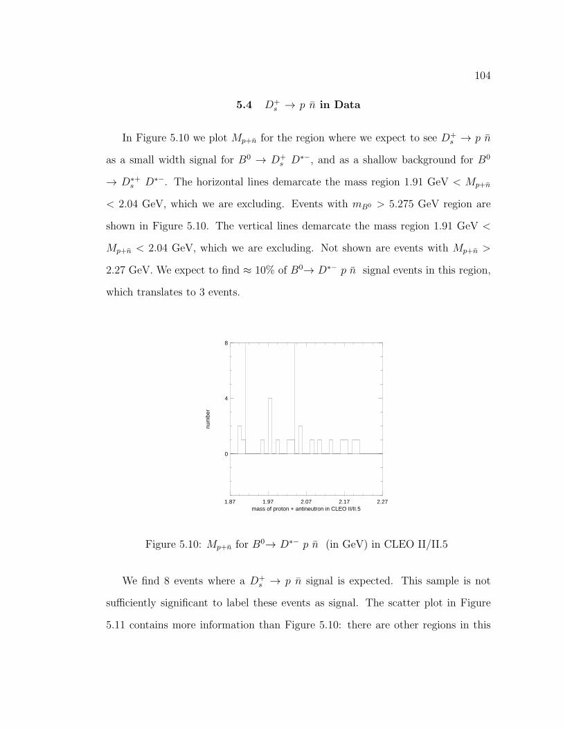
104
5.4 D+s → p n in Data
In Figure 5.10 we plot Mp+n for the region where we expect to see D+s → p n
as a small width signal for B0 → D+s D∗−, and as a shallow background for B0
→ D∗+s D∗−. The horizontal lines demarcate the mass region 1.91 GeV < Mp+n
< 2.04 GeV, which we are excluding. Events with mB0 > 5.275 GeV region are
shown in Figure 5.10. The vertical lines demarcate the mass region 1.91 GeV <
Mp+n < 2.04 GeV, which we are excluding. Not shown are events with Mp+n >
2.27 GeV. We expect to find ≈ 10% of B0→ D∗− p n signal events in this region,
which translates to 3 events.
1.87 1.97 2.07 2.17 2.27mass of proton + antineutron in CLEO II/II.5
0
4
8
num
ber
Figure 5.10: Mp+n for B0→ D∗− p n (in GeV) in CLEO II/II.5
We find 8 events where a D+s → p n signal is expected. This sample is not
sufficiently significant to label these events as signal. The scatter plot in Figure
5.11 contains more information than Figure 5.10: there are other regions in this

105
plot that are equally statistically significant to the region where we expect to find
D+s → p n. If we are to claim a signal in one, we should be able to claim one in
any of these others.
5.200 5.225 5.250 5.275 5.300B mass (in GeV) in CLEO II/II.5
1.87
2.07
2.27
2.47
2.67
mas
s of
pro
ton
+ a
ntin
eutr
on (
in G
eV)
Figure 5.11: Mp+n vs. mB0 (both in GeV)
We can, however, estimate an upper limit forD+s → p n. The most conservative
estimate is to call all 8 events in the expected region signal, which leads to a value
of 11.5 for a 90% confidence level measurement. 11.5 signal events correspond to
B(D+s → p n) < 5.4 % using the PDG value for B(B0 → D+
s D∗−).

106
5.5 B(B0→ D∗− p n ) Measurements.
We use the same equation to calculate B(B0→ D∗− p n ) as we did for B0→
D∗− p p π+ :
B(B0→ D∗− p p π+ ) = FittedY ield(2×B0B0×ǫMC)CLEOII+(2×B0B0×ǫMC)CLEOII.5
As we mentioned when calculating B(B0→D∗− p p π+ ), the product (BB × ǫMC)
is almost the same for CLEO II and CLEO II.5. The number of events for this
mode for MBC > 5.275 GeV is 10 for CLEO II, and 16 for CLEO II.5.
The combined mB0 distribution can be fitted to yield results that are consistent
with Monte Carlo expectations.
5.200 5.225 5.250 5.275 5.300B mass (GeV)
0
4
8
12
16
Com
bina
tions
/(2.
5 M
eV)
Figure 5.12: Inclusive mB0 in data for B0→ D∗− p n (in GeV)

107
5.200 5.225 5.250 5.275 5.300B mass (GeV)
0
2
4
6
8
10
12
14
Com
bina
tions
/(2.
5 M
eV)
Figure 5.13: mB0 in data for B0→ D∗− p n in GeV excluding both D+s → p n
contributions
Table 5.4: Measurements of B0→ D∗− p n branching fractions
Mode Yield Branching FractionB0→ D∗− p n inclusive 32.94+6.56
−5.92 14.9+3.0−2.7 × 10⁻⁴
B0→ D∗− p n without both contributions 24.02+5.60−4.96 11.9+2.8
−2.5 × 10⁻⁴
The difference in branching fractions does not imply that what has been ex-
cluded is only D+s → p n. We do not attempt to derive an upper limit by this
method. As in the case of our measurement of B0→ D∗− p p π+ , we find the
B0→ D∗− p n signal events are consistent with phase space decay. We look for a
resonance of type (cud) + (dd)strong → n+D∗−, and fail to find it.
The fits are quoted in Table 5.5. mB0 is fitted to a single Gaussian for signal,
and an Argus function for background. The offset is fixed at 0.0025, and the Ebeam

108
is fixed at 5.29 GeV in all the fits. As in the case of B0→ D∗− p p π+ , in table
5.5, leaving some parameters fixed, but not others allows us to test the validity of
our results. The excluded region is 1.91 GeV < Mp+n < 2.04 GeV.
Table 5.5: Results of various fits to mB0 for B0→ D∗− p n with or without theD+
s → p n contributions
Fitting options No D+s → p n Inclusive
floating valuesmB0 (MeV) 5, 280.3+0.60
−0.61 5, 280.5+0.50−0.52
σ (MeV) 2.59+0.49−0.41 2.43+0.46
−0.37
Fit Yield 23.57+5.61−4.97 31.48+6.52
−5.86
fixed mB0 = 5.28 GeVσ (MeV) 2.62+0.49
−0.42 2.55+0.47−0.40
Fit Yield 23.67+5.62−4.99 31.97+6.57
−5.93
fixed σ = 3.07 MeVmB0 (in MeV) 5, 280.3+0.68
−0.67 5, 280.3+0.60−0.60
Fit Yield 23.97+5.60−4.96 32.75+6.56
−5.91
fixed mB0 and σFit Yield 24.02+5.60
−4.96 32.94+6.56−5.92
B(B0→ D∗− p n ) × 10−4:From raw yield 11.9+2.8
−2.5 14.9+3.0−2.7
With MC Correction Factor 14.8+3.5−3.1 18.3+3.7
−3.3
In the following section we discuss the correction factor we apply to the raw
B(B0→ D∗− p n ) due to a discrepancy between data and Monte Carlo in the ǫp for
antiproton annihilation showers. The Correction Factor we use increases the raw
B(B0→ D∗− p n ) quoted in Table 5.5 by a factor of 1.21 with an added systematic
uncertainty of 4%.

109
5.6 Correction Factor
The Monte Carlo we use has not been optimized to model nucleon-antinucleon
annihilation. We find a discrepancy between the reconstruction efficiency for data
and Monte Carlo for antiprotons. We consider the discrepancy credible and change
the antineutron efficiency using a Correction Factor. We assume that the Monte
Carlo fails to model antineutrons by the same amount as it does for antiprotons,
even though the quark content of antiprotons and antineutrons is different.
We define ǫannihilation as the efficiency for an antibaryon shower to pass the
annihilation shower cuts outlined in Table 3.8. This quantity will be different for
antiprotons and antineutrons. In the former case we choose a sample which is
inevitably biased by the momentum range in which we can separate antiprotons
from other charged tracks. In the latter case we use a sample which has shower
backgrounds.
We define a correction factor to account for the discrepancy between data and
Monte Carlo for annihilation showers as:
Correction Factor =ǫannihilation,MC
ǫannihilation,Data
This Correction Factor is found for antiproton momentum bins in a range
consistent with the momentum range of antineutrons in B0→ D∗− p n as found
from the energy assigned to the antineutron candidate shower after assuming the
antineutron mass. The number of antineutrons in each of these momentum bins
is used to weigh the contribution of each bin to the Correction Factor, which is
defined for the entire range.

110
5.7 Use of a Λ Sample
The selection of a clean sample of antiprotons is achieved by reconstructing Λ’s.
In the decay Λ → pπ+, due to the large difference in mass between the p and the
π+, the kinematics of the decay allow for a clear separation of the p tracks from
the π+ tracks. Furthermore, the single Gaussian width of the mΛ distribution is 1
MeV and is affected by backgrounds insignificantly.
Antiprotons are selected with the same criteria used in the reconstruction of
B0→ D∗− p p π+ except for the use of Lproton > 0.1. Λ’s are from the KNVF
package [42]. The Λ selection criteria is as shown in Table 5.6.
Table 5.6: Λ selection criteria
Both tracks pass TRKMNG flag tng(track) ≥ 0χ2 of two tracks to form a vertex ≤ 30
χ2 for Λ to point back to the interaction region ≤ 30Significance of the two dimensional flight distance < 3σ
Flight distance ≥ 0.005 meter
We count the number of Λ’s in the signal region after applying a double Gaus-
sian fit with fixed parameters as shown in Table 5.7.
Table 5.7: Λ double Gaussian fixed parameters
Mass 1.1158 GeVσ1 0.00162
Area2/area1 0.46∆MEAN 0σ2/σ1 0.425

111
In Table 5.8 we find the % of antiproton showers in a Λ sample which pass
the annihilation shower cuts. In Table 5.8 we find ǫannihilation for MC and Data Λ
samples. The samples are a combination of ON and OFF resonance. The ON and
OFF resonance ǫannihilation’s were found to yield the same results.
Table 5.8: ǫannihilation: (%) of match 1 or 2 antiprotons in Λ’s passing annihilationshower selection cuts for six momentum spectra
CLEO II CLEO II CLEO II.5 CLEO II.5Momentum range MC Data MC Data
% % % %300-500 MeV 28.3 ± 1.3 13.2 ± 0.3 26.5 ± 1.0 13.3 ± 0.2500-700 MeV 65.1 ± 1.7 52.7 ± 0.9 65.0 ± 2.6 52.2 ± 0.6700-900 MeV 70.8 ± 1.8 60.6 ± 1.0 71.5 ± 2.8 60.9 ± 0.7900-1100 MeV 65.3 ± 1.7 52.9 ± 0.9 63.4 ± 2.5 50.7 ± 0.61100-1300 MeV 50.6 ± 2.0 41.9 ± 1.0 52.2 ± 2.1 41.4 ± 0.71300-1700 MeV 47.4 ± 1.9 44.0 ± 1.0 46.3 ± 1.8 41.0 ± 0.71700-2100 MeV 56.0 ± 2.0 54.0 ± 1.0 55.1 ± 1.9 53.2 ± 0.7
The Correction Factor is weighed according to the fraction of antineutrons in
a momentum range as produced in Monte Carlo. The solid distribution in Figure
5.14 is data and the dashed distribution is signal Monte Carlo.

112
bpnds. nptot axis
File: Generated internallyID IDB Symb Date/Time Area Mean R.M.S.
539 11 1 000417/1404 26.00 1.108 0.2619
0.1 0.55 1.0 1.45 1.9
0
4
539 4 2 000417/1407 26.01 1.077 0.3316
Figure 5.14: Antineutron momentum distribution (in GeV)

113
In Table 5.9 we calculate the Correction Factor as previously defined, as well
as the fraction of antineutrons found in signal Monte Carlo for each momentum
range.
Table 5.9: Correction Factor (C.F.) as a function of pproton and % of antineutronsfound in signal Monte Carlo for each momentum range in CLEO II/II.5
Momentum range % of n in MC C.F.300-500 MeV 9.1 2.07 ± 0.11500-700 MeV 10.0 1.25 ± 0.04700-900 MeV 14.7 1.17 ± 0.04900-1100 MeV 15.2 1.24 ± 0.041100-1300 MeV 16.3 1.23 ± 0.061300-1700 MeV 20.7 1.10 ± 0.051700-2100 MeV 15.7 1.04 ± 0.05300-1700 MeV 100.0 1.21 ± 0.05
We will use 1.21 as the Correction Factor by which to increase B(B0→ D∗− p
n ), which is an equally weighed average of CLEO II and CLEO II.5, and add to
our list of systematic errors a 4% contribution due to this correction.

114
5.7.1 Backgrounds in Signal and Generic Monte Carlo
To check that our antineutron selection criteria does not contaminate our sam-
ple with showers from decays similar to B0→ D∗− p n , we run our B0→ D∗− p n ,
with D0→K+π− reconstruction code on signal Monte Carlo for B0→ D∗∗ p n with
equal numbers of D1(2420)0 and D2
∗(2460)0, B0 → D∗−pnπ0, and B0 → D∗−p∆0
with ∆0 → nπ0. The result for mB0 are overlayed in solid on our data results, in
white, for B0→ D∗− p n in Figure 5.15.
Figure 5.15: mB0 in GeV for B0→ D∗− p n selection criteria applied to selectedsignal Monte Carlo background modes
We also run the B0→ D∗− p n code for all three D0 modes on our generic
Monte Carlo sample, as shown in Figure 5.16. The generic Monte Carlo sample is
discussed in Section 3.2. Scaling the generic Monte Carlo sample to the size of our
dataset, we find it to account for 40% of the background.

115
Within the generic MC sample ≈ 25% is combinatoric background events from
each of D0→K+π−π+π− and D0→K+π−. The remaining events, 50%, are from
D0→K+π−π0. Since B → D∗±NNX decays are not included in the generic MC,
these events are from random combinations of a B → Baryons decay and a B →
D∗ X decay.
Figure 5.16: mB0 for B0→ D∗− p n in GeV. (white) is data, (solid) is generic MC
We are unable to account for 60% of the background found in data in the mB0
distribution for B0→ D∗− p n . However, this background is small, and the mB0
distribution we find is consistent with a signal at the nominal B mass.
5.8 Antineutron Directional Cosine Resolution
We compare the generated and reconstructed directional cosines for the an-
tineutron candidates in signal Monte Carlo. We find the median error to be 37.8

116
milliradians. Since a single 5-cm calorimeter cell corresponds to ≈ 50 milliradians,
the systematic error in our measurement of the directional cosines of the antineu-
tron candidate shower is insignificant.
5.9 B0 → D∗+pn.
Neutrons do not annihilate in the calorimeter. Since our selection criteria for
antineutron showers rejects the vast majority of neutrons, we derive a new set of
cuts specific to neutrons. The selection criteria we used is shown in Figure 5.10.
The most important difference with antineutrons is the selection of low energy
photon-like showers.
Table 5.10: Neutron shower selection criteria
Track-to-shower match level type 3E9OE25 > cut 1
|(cos(θ)| < 0.71, or good barrelEmain < 500 MeV
We are unable to define selection criteria that allow us to separate neutrons
from soft photons. This background overwhelms the signal, making unatainable
the reconstruction of B0 → D∗+pn. We plot Emain for neutrons (solid distribution)
and antineutrons (dashed distribution) in Figure 5.17.

117
Figure 5.17: Emain (in GeV) for neutrons and antineutrons in B0→ D∗− p n signalMonte Carlo

118
5.10 Systematic Uncertainties
In Table 5.11 we show the systematic uncertainties we consider to contribute
significant errors to our measurement of B(B0→ D∗− p n ). B0→ D∗− p n has an
average of 4.6 tracks.
Table 5.11: Estimate of systematic uncertainties (in %) for B0→ D∗− p n
Source Uncertainty (in %)D0 branching fractions 0.6D∗ branching fraction 1.4D∗ reconstruction 5.0
Monte Carlo statistics 5.0# of BB’s 2.0
tracking (1%/track) 4.6PRLEV proton ID 4.0
∆ background contribution 5.0Phase space versus two body 3.0
antineutron miss-ID 15.0TOTAL 18.8 %

CHAPTER 6CONCLUSION
This work comprises the second successful exclusive reconstruction of B →
Baryons modes, after the exclusive reconstructions of B+ → Λcpπ+ and B0 →
Λcpπ+ π− carried out by CLEO in 1997 [29]. In Table 6.1 we summarize all the
exclusive B → Baryons measurements to date. We rank the modes from largest
to smallest branching fraction central value. The first error is statistical and the
second is systematic. The Λc modes have a third uncertainty, which is systematic
and is due to the error in the determination of B(Λ+c → pK−π+).
Table 6.1: Exclusive measurements in B → Baryons to date
Mode Branching Fraction (×10−4)B0→ D∗− p n 14.5+3.4
−3.0 ± 2.7B0 → Λcpπ
+ π− 13.3+4.6−4.2 ± 3.1± 2.1
B0→ D∗− p p π+ 6.6+1.3−1.2 ± 1.0
B+ → Λcpπ+ 6.2+2.3
−2.0 ± 1.1± 1.0
As shown in Table 6.1, the size of the branching fractions we are measuring
in this work are of the same order of magnitude as those previously measured in
decay modes including a Λc. We are unable to extrapolate the exclusive results
to compare the relative magnitude of the inclusive modes with or without a Λc.
For instance, the available phase space for the production of more light mesons
is larger in the case of modes with a Λc than in the case without, which may
cause the B → ΛcX inclusive rate to be larger than the B → [D]NNX inclusive
119

120
rate. However, we think it reasonable to assume that the measurements we have
at our disposal to date are representative of the inclusive modes. We infer that
B → [D]NNX modes contribute significantly to the total B → Baryons decay
rate.
6.1 B → Baryons phenomenology
The B → Baryons theoretical models attempted to date [48, 49] rely on the
assumption that the B meson decays to two decay daughters, which is the two-
body assumption. Unlike two-body B meson modes, most B → Baryons modes,
including all four that have been measured to date, have at least three decay
daughters. Most B → Baryons modes also have a varied resonant substructure.
The assumption that the hadronization process takes place at a late stage in the
decay, which allows for a substantial simplification of the equations due to the
suppressed dependence on the exchange of gluons and light quarks, is justified in
hard two-body decays. However, in many-body decays there can be re-scattering
of the hadronizing quarks and multiple exchanges of soft gluons and virtual quarks.
Notwithstanding the calculational difficulties of many-body B → Baryons decays
such as the ones we measure here, progress continues to be made using HQET to
explain B meson decay. The focus has been on decays for which HQET can be used
to extract the most information, and which can be used to search for CP violation
[14, 15]. Future attempts to theoretically explain B → Baryons are needed.

121
6.2 Possible Future B → Baryons Modes at CLEO
In CLEO II D0 reconstruction from B decays is plagued by high backgrounds
due to poor separation between kaons and pions. The substantial improvements in
charged particle separation (pion-kaon-proton) in the CLEO III data should allow
for the successful reconstruction of B+ → D0pn and B+ → D0ppπ+.
The ability to reconstruct antineutron modes should allow for the reconstruc-
tion of modes of type B → (Λc,Σc)nX . Modes of type B → (Λc∗,Σc
∗)pX , and
B → ΞcΛc, which have low reconstruction efficiencies in CLEO II/II.5, are also
worth pursuing.
B → Baryons for b → sg, and b → u modes will also be of interest and likely
within range. If previous measurements of the meson modes are used as a guide,
the modes B+ → Λp, B0 → pnπ−, and B0 → ppπ+π− are worth pursuing.
Semileptonic b→ c B → Baryons decays, such asB+ → Λc−pl+νl, with l = e, µ,
due to the low reconstruction efficiency at CLEO for low momentum leptons, have
not been measured. The substantially larger dataset expected in CLEO III may
compensate for the low reconstruction efficiency. A mode such as B+ → ppl+νl
should be feasible. This latter mode can be used as an auxiliary in the measurement
of |Vub|.
6.3 Significance of Results
We have found the first evidence of decay modes of the B0 of the type B →
DNNπ. We measure the branching fractions B (B0→ D∗− p p π+) = (6.5+1.3−1.2 ±
1.0)× 10−4, and B( B0→D∗− p n ) = (14.8+3.5−3.1 ± 3.0)× 10−4. These measurements

122
indicate the fraction of baryonic decays of B mesons that do not proceed via Λ+c
may be of approximately the same magnitude as those that do.

REFERENCES
[1] Abraham Pais, Inward Bound, Clarendon Press, Oxford, 1986.
[2] The Particle Hunters. Y. Ne’eman and Y. Kirsh, Cambridge University Press,1996.
[3] An Introduction to Quantum Field Theory. Michael E. Peskin and Daniel V.Schroeder, Addison Wesley, 1998.
[4] Dynamics of the Standard Model. John F. Donogue, Eugene Golowich andBarry R. Holstein, Cambridge University Press, 1992.
[5] Particle Data Group. Review of particle physics. The European PhysicalJournal C, 3(1-4), 1998. The current web edition is http://pdg.lbl.gov/.
[6] Y. Fukuda et al. (The Super-Kamiokande collaboration), hep-ex/9909022and Phys. Rev. Lett 81, 1562, 1998.
[7] V. Fanti et al. (The NA48 Collaboration) Phys.Lett. B465, 335-348, 1999.
[8] B. H. Bherens et al. (CLEO Collaboration) hep-ex/0005013. Submitted toPhys. Rev. Lett.
[9] D. J. Gross and F. Wilczek, Phys. Rev. Lett. 30, 1343, 1973.
[10] H. D. Politzer, Phys. Rev. Lett. 30, 1346, 1973.
[11] Chris Quigg, Gauge Theories of the Strong, Weak, and Electromagnetic In-teractions, Benjamin/Cummins, 1983.
[12] M. B. Voloshin, Inclusive Weak Deacy Rates of Heavy Hadrons. hep-ph/0004257.
[13] M. Shifman, Snapshots of Hadrons. hep-ph/9802214.
[14] Mathias Neubert. Introduction to B physics. hep-ph/0001334.
[15] Mark B. Wise. Heavy Quark physics. hep-ph/9805468.
123

124
[16] N. Isgur and M.B. Wise, Phys. Lett B 237, 527, 1990.
[17] Karl M .Ecklund. Semileptonic B decays at CLEO. hep-ex/9912034.
[18] M. E. Luke, Phys. Lett B 252, 447, 1990.
[19] M. Bauer, B. Stech and M. Wirbel, Z. Phys. C 34, 103, 1987.
[20] Mathias Neubert. Non-Leptonic Weak Decays of B mesons. hep-ph/9705292.
[21] A. J. Buras and L. Silvestrini. Non-Leptonic Two-Body B Decays BeyondFactorization. hep-ph/9812392.
[22] K. G. Wilson, Phys. Rev. 179, 1499, 1969.
[23] A. J. Buras. Operator Product Expansion, Renormalization Group andWeakDecays. hep-ph/9901409.
[24] G. Crawford et al. (CLEO Collaboration) Phys. Rev. D 45: 752, 1992
[25] M. Procario et al. (CLEO Collaboration) Phys. Rev. Lett 73, 1472, 1994.
[26] B. Barish et al. (CLEO Collaboration) Phys. Rev. Lett 79, 3599-3603, 1997.
[27] G. Bonvicini et al. (CLEO Collaboration) Phys. Rev. D57: 6604-6608, 1998.
[28] T. E. Coan et al. (CLEO Collaboration) Phys. Rev. D59: 111101, 1999.
[29] X. Fu et al. (CLEO Collaboration) Phys. Rev. Lett 79, 3125, 1997.
[30] D. Jaffe et al. (The CLEO Collaboration), CLEO 00-3, accepted for publi-cation in Phys. Rev. D.
[31] M. Zoeller, Ph. D. Thesis, State University of New York, Albany, 1994 (un-published).
[32] I. Dunietz. Phys. Rev. D58: 094010-1, 1998.
[33] Y. Kubota et al. Nucl. Instrum. Methods Phys. Res. A 320, 66, 1992.
[34] Introduction to High Energy Physics. Donald H. Perkins, Addison-Wesley,1987.
[35] T. Hill. Nucl. Instrum. Methods Phys. Res. A 418, 32-39, 1998.
[36] I. Brock, Mn fit: A fitting and Plotting Package Using Minuit. L3 Note, 918,1995.

125
[37] Minuit: Function Minimization and Error Analysis. CERN Program Library,D506.
[38] G. C. Fox and S. Wolfrum, Phys. Rev. Lett. 41, 1581, 1978.
[39] L. Gibbons et al. CLEO CBX, 96/103, 1996 (unpublished).
[40] L. Gibbons et al. (CLEO Collaboration) Phys. Rev. D 56, 3783, 1997.
[41] P. Avery. KNLIB documentation. http://www.phys.ufl.edu/avery/kwfit
[42] C. Prescott. The knvf secondary vertex fitting package. CLEO CSN, 97/353,1997 (unpublished).
[43] C. Amsler. Rev. Mod. Phys. 70 No.4, 1293, 1998.
[44] C. Amsler et al. Annu. Rev. Nuc. Part. Sc. Vol 41, p219, 1991.
[45] G. Brandenburg et al. (CLEO Collaboration) Phys. Rev. Lett 80, 2762-2766,1998.
[46] J. Rodriguez et al. CLEO CBX, 96/64, 1996 (unpublished).
[47] A. Foland. CLEO CBX, 97/70, 1997 (unpublished).
[48] M. Jarfi et al. Phys. Rev. D 43, 1599, 1991.
[49] N. G. Deshpande et al. Mod. Phys. Lett. A 3, 749, 1988.

BIOGRAPHICAL SKETCH
Antonio Rubiera was born in Havana, Cuba on January 21, 1967. He came
to the U.S. by the Mariel boatlift in 1980. He attended Shenandoah Jr. High
and Miami Sr. High in Miami, Florida. From 1986 to 1991 he attended Cornell
University, obtaining a B.S. and an M.Eng., both in Electrical Engineering. From
1991 to 1994 he resided in Miami, where he worked for the Latin America branch
of Ingersoll-Rand Co. He pursued a PhD in physics at the University of Florida
from 1995 to 2000.
126

5.200 5.225 5.250 5.275 5.300beam constained mass (GeV) in CLEO II.5
-0.10
-0.05
0.00
0.05
0.10
delta
E (
GeV
)

5.200 5.225 5.250 5.275 5.300Beam constrained mass (GeV)
0
4
8
12
16
Com
bina
tions
/(2
MeV
)