Artifacts of the Process - IBM - United States · Artifacts of the Process ... included in this set...
26
83 C H A P T E R 6 Artifacts of the Process onventional software projects focused on the sequential development of software artifacts: build the requirements, construct a design model traceable to the requirements, build an implementation traceable to the design model, and compile and test the imple- mentation for deployment. This process can work for small-scale, purely custom develop- ments in which the design representation, implementation representation, and deploy- ment representation are closely aligned. For example, a single program that is intended to run on a single computer of a single type and is composed entirely of special-purpose custom components can be constructed with straightforward traceability among all the representations. However, this approach doesn’t work very well for most of today’s software sys- tems, in which the system complexity (in many dimensions) results in such numerous risks and subtle traceability relationships that you cannot efficiently use a simplistic sequential transformation. Most modern systems are composed of numerous compo- nents (some custom, some reused, some commercial products) intended to execute in a heterogeneous network of distributed platforms. They require a very different sequence of artifact evolution and a very different approach to traceability. Over the past 20 years, the software industry has matured and has transitioned the management process to be iterative. Rather than being built sequentially, the arti- facts are evolved together, and the constraints, the different levels of abstractions, and the degrees of freedom are balanced among competing alternatives. Recurring themes Key Points ▲ The artifacts of the process are orga- nized into five sets: management, requirements, design, implementation, and deployment. ▲ The management artifacts capture the information necessary to synchro- nize stakeholder expectations. ▲ The requirements, design, implemen- tation, and deployment artifacts are captured in rigorous notations that sup- port automated analysis and browsing. C chpt 6.typ Page 83 Friday, October 27, 2000 10:34 AM Black process 45.0° 133.0 LPI
Transcript of Artifacts of the Process - IBM - United States · Artifacts of the Process ... included in this set...

83
C H A P T E R 6
Artifacts of the Process
onventional software projects focused onthe sequential development of software
artifacts: build the requirements, construct adesign model traceable to the requirements,build an implementation traceable to thedesign model, and compile and test the imple-mentation for deployment. This process canwork for small-scale, purely custom develop-ments in which the design representation,implementation representation, and deploy-ment representation are closely aligned. Forexample, a single program that is intended torun on a single computer of a single type and is composed entirely of special-purposecustom components can be constructed with straightforward traceability among allthe representations.
However, this approach doesn’t work very well for most of today’s software sys-tems, in which the system complexity (in many dimensions) results in such numerousrisks and subtle traceability relationships that you cannot efficiently use a simplisticsequential transformation. Most modern systems are composed of numerous compo-nents (some custom, some reused, some commercial products) intended to execute ina heterogeneous network of distributed platforms. They require a very differentsequence of artifact evolution and a very different approach to traceability.
Over the past 20 years, the software industry has matured and has transitionedthe management process to be iterative. Rather than being built sequentially, the arti-facts are evolved together, and the constraints, the different levels of abstractions, andthe degrees of freedom are balanced among competing alternatives. Recurring themes
Key Points▲ The artifacts of the process are orga-nized into five sets: management, requirements, design, implementation, and deployment.
▲ The management artifacts capture the information necessary to synchro-nize stakeholder expectations.
▲ The requirements, design, implemen-tation, and deployment artifacts are captured in rigorous notations that sup-port automated analysis and browsing.
C
chpt 6.typ Page 83 Friday, October 27, 2000 10:34 AM
Black process 45.0° 133.0 LPI
84
ARTIFACTS OF THE PROCESS
from successful projects demonstrate that the software artifacts evolve together withbalanced levels of detail. Artifacts do not evolve in a one-way, linear progression fromrequirements to design to implementation to deployment. Choices about implementa-tion and deployment affect the way in which the requirements are stated and the wayin which the design proceeds. Information and decisions can flow in various waysamong artifacts. The purpose of a good development process is to remove inappropri-ate, premature constraints on the design and to accommodate the real engineeringconstraints.
And what is the impact of iterative development on evolving artifacts? The pri-mary difference from the conventional approach is that within each life-cycle phase,the workflow activities do not progress in a simple linear way, nor does artifact build-ing proceed monotonically from one artifact to another. Instead, the focus of activitiessweeps across artifacts repeatedly, incrementally enriching the entire system descrip-tion and the process with the lessons learned in preserving balance across the breadthand depth of information.
6.1 THE ARTIFACT SETS
To make the development of a complete software system manageable, distinct collec-tions of information are organized into artifact sets. Each set comprises related arti-facts that are persistent and in a uniform representation format (such as English text,C++, Visual Basic, Java, a standard document template, a standard spreadsheet tem-plate, or a UML model). While a
set
represents a complete aspect of the system, an
artifact
represents cohesive information that typically is developed and reviewed as asingle entity. In any given organization, project, or system, some of these artifacts—and even some sets—may be trivial or unnecessary. In general, however, some infor-mation needs to be captured in each set to satisfy all stakeholders.
Life-cycle software artifacts are organized into five distinct sets that are roughlypartitioned by the underlying language of the set: management (ad hoc textual for-mats), requirements (organized text and models of the problem space), design (modelsof the solution space), implementation (human-readable programming language andassociated source files), and deployment (machine-processable languages and associ-ated files).
The emergence of rigorous and more powerful engineering notations for re-quirements and design artifacts that support architecture-first development was amajor technology advance. In particular, the Unified Modeling Language has evolvedinto a suitable representation format, namely visual models with a well-specified syn-tax and semantics for requirements and design artifacts. Visual modeling using UMLis a primitive notation for early life-cycle artifacts. The artifact sets are shown inFigure 6-1; their purposes and notations are described next.
chpt 6.typ Page 84 Friday, October 27, 2000 10:34 AM
Black process 45.0° 133.0 LPI

6.1 THE ARTIFACT SETS
85
6.1.1 T
HE
M
ANAGEMENT
S
ET
The management set captures the artifacts associated with process planning and exe-cution. These artifacts use ad hoc notations, including text, graphics, or whatever rep-resentation is required to capture the “contracts” among project personnel (projectmanagement, architects, developers, testers, marketers, administrators), among stake-holders (funding authority, user, software project manager, organization manager,regulatory agency), and between project personnel and stakeholders. Specific artifactsincluded in this set are the work breakdown structure (activity breakdown and finan-cial tracking mechanism), the business case (cost, schedule, profit expectations), therelease specifications (scope, plan, objectives for release baselines), the software devel-opment plan (project process instance), the release descriptions (results of releasebaselines), the status assessments (periodic snapshots of project progress), the soft-ware change orders (descriptions of discrete baseline changes), the deployment docu-ments (cutover plan, training course, sales rollout kit), and the environment(hardware and software tools, process automation, documentation, training collat-eral necessary to support the execution of the process described in the software devel-opment plan and the production of the engineering artifacts).
Management SetPlanning Artifacts
1. Work breakdown structure2. Business case3. Release specifications4. Software development plan
Operational Artifacts
5. Release descriptions6. Status assessments7. Software change order database8. Deployment documents9. Environment
Requirements Set
1. Vision document2. Requirements
model(s)
Implementation Set
1. Source codebaselines
2. Associatedcompile-time
files3. Component
executables
Deployment Set
1. Integrated productexecutablebaselines
2. Associated run-time files3. User manual
1. Design model(s)2. Test model3. Software
architecturedescription
Design Set
FIGURE 6-1. Overview of the artifact sets
chpt 6.typ Page 85 Friday, October 27, 2000 10:34 AM
Black process 45.0° 133.0 LPI

86
ARTIFACTS OF THE PROCESS
Management set artifacts are evaluated, assessed, and measured through a com-bination of the following:
• Relevant stakeholder review
• Analysis of changes between the current version of the artifact and previ-ous versions (management trends and project performance changes interms of cost, schedule, and quality)
• Major milestone demonstrations of the balance among all artifacts and, inparticular, the accuracy of the business case and vision artifacts
6.1.2 T
HE
E
NGINEERING
S
ETS
The engineering sets consist of the requirements set, the design set, the implementa-tion set, and the deployment set. The primary mechanism for evaluating the evolvingquality of each artifact set is the transitioning of information from set to set, therebymaintaining a balance of understanding among the requirements, design, implemen-tation, and deployment artifacts. Each of these components of the system descriptionevolves over time.
Requirements Set
Structured text is used for the vision statement, which documents the project scopethat supports the contract between the funding authority and the project team. Adhoc formats may also be used for supplementary specifications (such as regulatoryrequirements) and user mockups or other prototypes that capture requirements. UMLnotation is used for engineering representations of requirements models (use casemodels, domain models). The requirements set is the primary engineering context forevaluating the other three engineering artifact sets and is the basis for test cases.
Requirements artifacts are evaluated, assessed, and measured through a combi-nation of the following:
• Analysis of consistency with the release specifications of the managementset
• Analysis of consistency between the vision and the requirements models
• Mapping against the design, implementation, and deployment sets to eval-uate the consistency and completeness and the semantic balance betweeninformation in the different sets
• Analysis of changes between the current version of requirements artifactsand previous versions (scrap, rework, and defect elimination trends)
• Subjective review of other dimensions of quality
chpt 6.typ Page 86 Friday, October 27, 2000 10:34 AM
Black process 45.0° 133.0 LPI

6.1 THE ARTIFACT SETS
87
Design Set
UML notation is used to engineer the design models for the solution. The design setcontains varying levels of abstraction that represent the components of the solutionspace (their identities, attributes, static relationships, dynamic interactions). Thedesign models include enough structural and behavioral information to ascertain abill of materials (quantity and specification of primitive parts and materials, labor,and other direct costs). Design model information can be straightforwardly and, inmany cases, automatically translated into a subset of the implementation and deploy-ment set artifacts. Specific design set artifacts include the design model, the test model,and the software architecture description (an extract of information from the designmodel that is pertinent to describing an architecture).
The design set is evaluated, assessed, and measured through a combination ofthe following:
• Analysis of the internal consistency and quality of the design model
• Analysis of consistency with the requirements models
• Translation into implementation and deployment sets and notations (forexample, traceability, source code generation, compilation, linking) toevaluate the consistency and completeness and the semantic balancebetween information in the sets
• Analysis of changes between the current version of the design model andprevious versions (scrap, rework, and defect elimination trends)
• Subjective review of other dimensions of quality
Because the level of automated analysis available on design models is currentlylimited, human analysis must be relied on. This situation should change over the nextfew years with the maturity of design model analysis tools that support metrics collec-tion, complexity analysis, style analysis, heuristic analysis, and consistency analysis.
Implementation Set
The implementation set includes source code (programming language notations) thatrepresents the tangible implementations of components (their form, interface, anddependency relationships) and any executables necessary for stand-alone testing ofcomponents. These executables are the primitive parts needed to construct the endproduct, including custom components, application programming interfaces (APIs) ofcommercial components, and APIs or reusable or legacy components in a program-ming language source (such as Ada 95, C++, Visual Basic, Java, or Assembly). Imple-mentation set artifacts can also be translated (compiled and linked) into a subset of
chpt 6.typ Page 87 Friday, October 27, 2000 10:34 AM
Black process 45.0° 133.0 LPI

88
ARTIFACTS OF THE PROCESS
the deployment set (end-target executables). Specific artifacts include self-document-ing product source code baselines and associated files (compilation scripts, configura-tion management infrastructure, data files), self-documenting test source codebaselines and associated files (input test data files, test result files), stand-alone com-ponent executables, and component test driver executables.
Implementation sets are human-readable formats that are evaluated, assessed,and measured through a combination of the following:
• Analysis of consistency with the design models
• Translation into deployment set notations (for example, compilation andlinking) to evaluate the consistency and completeness among artifact sets
• Assessment of component source or executable files against relevant evalu-ation criteria through inspection, analysis, demonstration, or testing
• Execution of stand-alone component test cases that automatically compareexpected results with actual results
• Analysis of changes between the current version of the implementation setand previous versions (scrap, rework, and defect elimination trends)
• Subjective review of other dimensions of quality
Deployment Set
The deployment set includes user deliverables and machine language notations, exe-cutable software, and the build scripts, installation scripts, and executable target-specific data necessary to use the product in its target environment. These machinelanguage notations represent the product components in the target form intended fordistribution to users. Deployment set information can be installed, executed againstscenarios of use (tested), and dynamically reconfigured to support the featuresrequired in the end product. Specific artifacts include executable baselines and associ-ated run-time files, and the user manual.
Deployment sets are evaluated, assessed, and measured through a combinationof the following:
• Testing against the usage scenarios and quality attributes defined in therequirements set to evaluate the consistency and completeness and thesemantic balance between information in the two sets
• Testing the partitioning, replication, and allocation strategies in mappingcomponents of the implementation set to physical resources of the deploy-ment system (platform type, number, network topology)
chpt 6.typ Page 88 Friday, October 27, 2000 10:34 AM
Black process 45.0° 133.0 LPI

6.1 THE ARTIFACT SETS
89
• Testing against the defined usage scenarios in the user manual such asinstallation, user-oriented dynamic reconfiguration, mainstream usage, andanomaly management
• Analysis of changes between the current version of the deployment set andprevious versions (defect elimination trends, performance changes)
• Subjective review of other dimensions of quality
The rationale for selecting the management, requirements, design, implementa-tion, and deployment sets was not scientific. The goal was to optimize presentation ofthe process activities, artifacts, and objectives. Some of the rationale that resulted inthis conceptual framework is described next. Although there are several minor excep-tions to these generalizations, they are useful in understanding the overall artifact sets.
Each artifact set uses different notation(s) to capture the relevant artifacts. Man-agement set notations (ad hoc text, graphics, use case notation) capture the plans,process, objectives, and acceptance criteria. Requirements notations (structured textand UML models) capture the engineering context and the operational concept.Design notations (in UML) capture the engineering blueprints (architectural design,component design). Implementation notations (software languages) capture thebuilding blocks of the solution in human-readable formats. Deployment notations(executables and data files) capture the solution in machine-readable formats.
Each artifact set is the predominant development focus of one phase of the lifecycle; the other sets take on check and balance roles. As illustrated in Figure 6-2, each
FIGURE 6-2. Life-cycle focus on artifact sets
Inception Elaboration Construction Trans ition
Requirements
Design
Implementation
Deployment
Management
chpt 6.typ Page 89 Friday, October 27, 2000 10:34 AM
Black process 45.0° 133.0 LPI

90
ARTIFACTS OF THE PROCESS
phase has a predominant focus: Requirements are the focus of the inception phase;design, the elaboration phase; implementation, the construction phase; and deploy-ment, the transition phase. The management artifacts also evolve, but at a fairly con-stant level across the life cycle.
Most of today’s software development tools map closely to one of the five arti-fact sets.
1. Management: scheduling, workflow, defect tracking, change management,documentation, spreadsheet, resource management, and presentation tools
2. Requirements: requirements management tools
3. Design: visual modeling tools
4. Implementation: compiler/debugger tools, code analysis tools, test cover-age analysis tools, and test management tools
5. Deployment: test coverage and test automation tools, network manage-ment tools, commercial components (operating systems, GUIs, DBMSs,networks, middleware), and installation tools
Allocation of responsibilities among project teams is straightforward and alignswith the process workflows presented in Chapter 8.
Implementation Set versus Deployment Set
The separation of the implementation set (source code) from the deployment set (exe-cutable code) is important because there are very different concerns with each set. Thestructure of the information delivered to the user (and typically the test organization)is very different from the structure of the source code information. Engineering deci-sions that have an impact on the quality of the deployment set but are relativelyincomprehensible in the design and implementation sets include the following:
• Dynamically reconfigurable parameters (buffer sizes, color palettes, numberof servers, number of simultaneous clients, data files, run-time parameters)
• Effects of compiler/link optimizations (such as space optimization versusspeed optimization)
• Performance under certain allocation strategies (centralized versus distrib-uted, primary and shadow threads, dynamic load balancing, hot backupversus checkpoint/rollback)
• Virtual machine constraints (file descriptors, garbage collection, heap size,maximum record size, disk file rotations)
chpt 6.typ Page 90 Friday, October 27, 2000 10:34 AM
Black process 45.0° 133.0 LPI

6.1 THE ARTIFACT SETS
91
• Process-level concurrency issues (deadlock and race conditions)
• Platform-specific differences in performance or behavior
Much of this configuration information is important engineering source datathat should be captured either in the implementation set (if it is embedded withinsource code) or in the deployment set (if it is embedded within data files, configura-tion files, installation scripts, or other target-specific components). In dynamicallyreconfigurable systems or portable components, it is usually better to separate thesource code implementation concerns from the target environment concerns (for rea-sons of performance, dynamic adaptability, or source code change management).With this approach, the implementation can be decoupled from the actual platformtype and from the number and topology of the underlying computing infrastructure,which includes operating systems, middleware, networks, and DBMSs.
As an example, consider the software architecture of a one million SLOC missilewarning system (a project described in detail in the case study, Appendix D) withextreme requirements for fault tolerance and data processing performance. On thisproject, significantly different configurations of executables could be built from thesame source sets.
• A version that includes only the primary thread of processing on a develop-ment host to do a subset of scenario tests
• A version that includes primary and backup processing threads on a devel-opment host, which could then exercise some of the logical reconfigurationscenarios
• Functionally equivalent versions of the two preceding configurations thatcould execute on the target processors to assess the required throughputand response time of the critical-thread scenarios on the candidate targetconfiguration
• A version that could execute a primary thread of servers on one target pro-cessor, a shadow thread of servers on a separate backup target processor, atest/exercise thread on either target, and a suite of thread-independent userinterface clients on user workstations. The latter, which could support abroad range of dynamic reconfigurations, was essentially the final targetconfiguration.
Deployment of commercial products to customers can also span a broad rangeof test and deployment configurations. For example, middleware products providehigh-performance, reliable object request brokers that are delivered on several platformimplementations, including workstation operating systems, bare embedded processors,
chpt 6.typ Page 91 Friday, October 27, 2000 10:34 AM
Black process 45.0° 133.0 LPI

92
ARTIFACTS OF THE PROCESS
large mainframe operating systems, and several real-time operating systems. Theproduct configurations support various compilers and languages as well as variousimplementations of network software. The heterogeneity of all the various target con-figurations results in the need for a highly sophisticated source code structure and ahuge suite of different deployment artifacts.
6.1.3 A
RTIFACT
E
VOLUTION
OVER
THE
L
IFE
C
YCLE
Each state of development represents a certain amount of precision in the final systemdescription. Early in the life cycle, precision is low and the representation is generallyhigh. Eventually, the precision of representation is high and everything is specified infull detail. At any point in the life cycle, the five sets will be in different states of com-pleteness. However, they should be at compatible levels of detail and reasonablytraceable to one another. Performing detailed traceability and consistency analysesearly in the life cycle (when precision is low and changes are frequent) usually has alow return on investment. As development proceeds, the architecture stabilizes, andmaintaining traceability linkage among artifact sets is worth the effort.
Each phase of development focuses on a particular artifact set. At the end ofeach phase, the overall system state will have progressed on all sets, as illustrated inFigure 6-3.
The inception phase focuses mainly on critical requirements, usually with a sec-ondary focus on an initial deployment view, little focus on implementation except per-haps choice of language and commercial components, and possibly some high-levelfocus on the design architecture but not on design detail.
During the elaboration phase, there is much greater depth in requirements,much more breadth in the design set, and further work on implementation anddeployment issues such as performance trade-offs under primary scenarios and make/buy analyses. Elaboration phase activities include the generation of an executable
Inception Elaboration Construction Transition
Engineering Stage Production Stage
Req
uire
men
ts
Des
ign
Impl
emen
tatio
n
Dep
loym
ent
Management
Req
uire
men
ts
Des
ign
Impl
emen
tatio
n
Dep
loym
ent
Management
Req
uire
men
ts
Des
ign
Impl
emen
tatio
n
Dep
loym
ent
Management
Req
uire
men
ts
Des
ign
Impl
emen
tatio
n
Dep
loym
ent
Management
FIGURE 6-3. Life-cycle evolution of the artifact sets
chpt 6.typ Page 92 Friday, October 27, 2000 10:34 AM
Black process 45.0° 133.0 LPI

6.1 THE ARTIFACT SETS
93
prototype. This prototype involves subsets of development in all four sets and specifi-cally assesses whether the interfaces and collaborations among components are con-sistent and complete within the context of the system’s primary requirements andscenarios. Although there is generally a broad understanding of component inter-faces, there is usually not much depth in implementation for custom components.(However, commercial or other existing components may be fully elaborated.) A por-tion of all four sets must be evolved to some level of completion before an architecturebaseline can be established. This evolution requires sufficient assessment of the designset, implementation set, and deployment set artifacts against the critical use cases ofthe requirements set to suggest that the project can proceed predictably with well-understood risks.
The main focus of the construction phase is design and implementation. Themain focus early in this phase should be the depth of the design artifacts. Later in con-struction, the emphasis is on realizing the design in source code and individuallytested components. This phase should drive the requirements, design, and implemen-tation sets almost to completion. Substantial work is also done on the deployment set,at least to test one or a few instances of the programmed system through a mechanismsuch as an alpha or beta release.
The main focus of the transition phase is on achieving consistency and complete-ness of the deployment set in the context of the other sets. Residual defects areresolved, and feedback from alpha, beta, and system testing is incorporated.
As development proceeds, each of the parts evolves in more detail. When the sys-tem is complete, all four sets are fully elaborated and consistent with one another. Incontrast to the conventional practice, you do not specify the requirements, then do thedesign, and so forth. Instead, you evolve the entire system; decisions about the deploy-ment may affect requirements, not just the other way around. The key emphasis hereis to break the conventional mold, in which the default interpretation is that one setprecedes another. Instead, one state of the entire system evolves into a more elaboratestate of the system, usually involving evolution in each of the parts. During the transi-tion phase, traceability between the requirements set and the deployment set isextremely important. The evolving requirements set captures a mature and preciserepresentation of the stakeholders’ acceptance criteria, and the deployment set repre-sents the actual end-user product. Therefore, during the transition phase, complete-ness and consistency between these two sets are important. Traceability among theother sets is necessary only to the extent that it aids the engineering or managementactivities.
6.1.4 T
EST
A
RTIFACTS
Conventional software testing followed the same document-driven approach that wasapplied to software development. Development teams built requirements documents,
chpt 6.typ Page 93 Friday, October 27, 2000 10:34 AM
Black process 45.0° 133.0 LPI

94
ARTIFACTS OF THE PROCESS
top-level design documents, and detailed design documents before constructing anysource files or executables. Similarly, test teams built system test plan documents, sys-tem test procedure documents, integration test plan documents, unit test plan docu-ments, and unit test procedure documents before building any test drivers, stubs, orinstrumentation. This document-driven approach caused the same problems for thetest activities that it did for the development activities.
One of the truly discriminating tenets of a modern process is to use exactly thesame sets, notations, and artifacts for the products of test activities as are used forproduct development. In essence, we are simply identifying the test infrastructure nec-essary to execute the test process as a required subset of the end product. By doingthis, we have forced several engineering disciplines into the process.
• The test artifacts must be developed concurrently with the product frominception through deployment. Thus, testing is a full-life-cycle activity, nota late life-cycle activity.
• The test artifacts are communicated, engineered, and developed within thesame artifact sets as the developed product.
• The test artifacts are implemented in programmable and repeatable for-mats (as software programs).
• The test artifacts are documented in the same way that the product is docu-mented.
• Developers of the test artifacts use the same tools, techniques, and trainingas the software engineers developing the product.
These disciplines allow for significant levels of homogenization across projectworkflows, which are described in Chapter 8. Everyone works within the notationsand techniques of the four sets used for engineering artifacts, rather than with sepa-rate sequences of design and test documents. Interpersonal communications, stake-holder reviews, and engineering analyses can be performed with fewer distinctformats, fewer ad hoc notations, less ambiguity, and higher efficiency.
Testing is only one aspect of the assessment workflow. Other aspects includeinspection, analysis, and demonstration. Testing refers to the explicit evaluationthrough execution of deployment set components under a controlled scenario with anexpected and objective outcome. The success of a test can be determined by compar-ing the expected outcome to the actual outcome with well-defined mathematicalprecision. Tests are exactly the forms of assessment that are automated.
Although the test artifact subsets are highly project-specific, the following exam-ple clarifies the relationship between test artifacts and the other artifact sets. Considera project to perform seismic data processing for the purpose of oil exploration. This
chpt 6.typ Page 94 Friday, October 27, 2000 10:34 AM
Black process 45.0° 133.0 LPI

6.1 THE ARTIFACT SETS
95
system has three fundamental subsystems: (1) a sensor subsystem that captures rawseismic data in real time and delivers these data to (2) a technical operations sub-system that converts raw data into an organized database and manages queries to thisdatabase from (3) a display subsystem that allows workstation operators to examineseismic data in human-readable form. Such a system would result in the following testartifacts:
• Management set. The release specifications and release descriptions cap-ture the objectives, evaluation criteria, and results of an intermediate mile-stone. These artifacts are the test plans and test results negotiated amonginternal project teams. The software change orders capture test results(defects, testability changes, requirements ambiguities, enhancements) andthe closure criteria associated with making a discrete change to a baseline.
• Requirements set.
The system-level use cases capture the operational con-cept for the system and the acceptance test case descriptions, including theexpected behavior of the system and its quality attributes. The entirerequirements set is a test artifact because it is the basis of all assessmentactivities across the life cycle.
• Design set. A test model for nondeliverable components needed to test theproduct baselines is captured in the design set. These components includesuch design set artifacts as a seismic event simulation for creating realisticsensor data; a “virtual operator” that can support unattended, after-hourstest cases; specific instrumentation suites for early demonstration ofresource usage; transaction rates or response times; and use case test driv-ers and component stand-alone test drivers.
• Implementation set. Self-documenting source code representations for testcomponents and test drivers provide the equivalent of test procedures andtest scripts. These source files may also include human-readable data filesrepresenting certain statically defined data sets that are explicit test sourcefiles. Output files from test drivers provide the equivalent of test reports.
• Deployment set. Executable versions of test components, test drivers, anddata files are provided.
For any release, all the test artifacts and product artifacts are maintained usingthe same baseline version identifier. They are created, changed, and obsolesced as aconsistent unit. Because test artifacts are captured using the same notations, methods,and tools, the approach to testing is consistent with design and development. Thisapproach forces the evolving test artifacts to be maintained so that regression testingcan be automated easily.
chpt 6.typ Page 95 Friday, October 27, 2000 10:34 AM
Black process 45.0° 133.0 LPI
96
ARTIFACTS OF THE PROCESS
6.2 MANAGEMENT ARTIFACTS
The management set includes several artifacts that capture intermediate results andancillary information necessary to document the product/process legacy, maintain theproduct, improve the product, and improve the process. These artifacts are summa-rized next and discussed in detail in subsequent chapters, where the managementworkflows and activities are elaborated. Although the following descriptions use theword
document
to describe certain artifacts, this is only meant to imply that the data
could
be committed to a paper document. In many cases, the data may be processed,reviewed, and exchanged via electronic means only.
Business Case
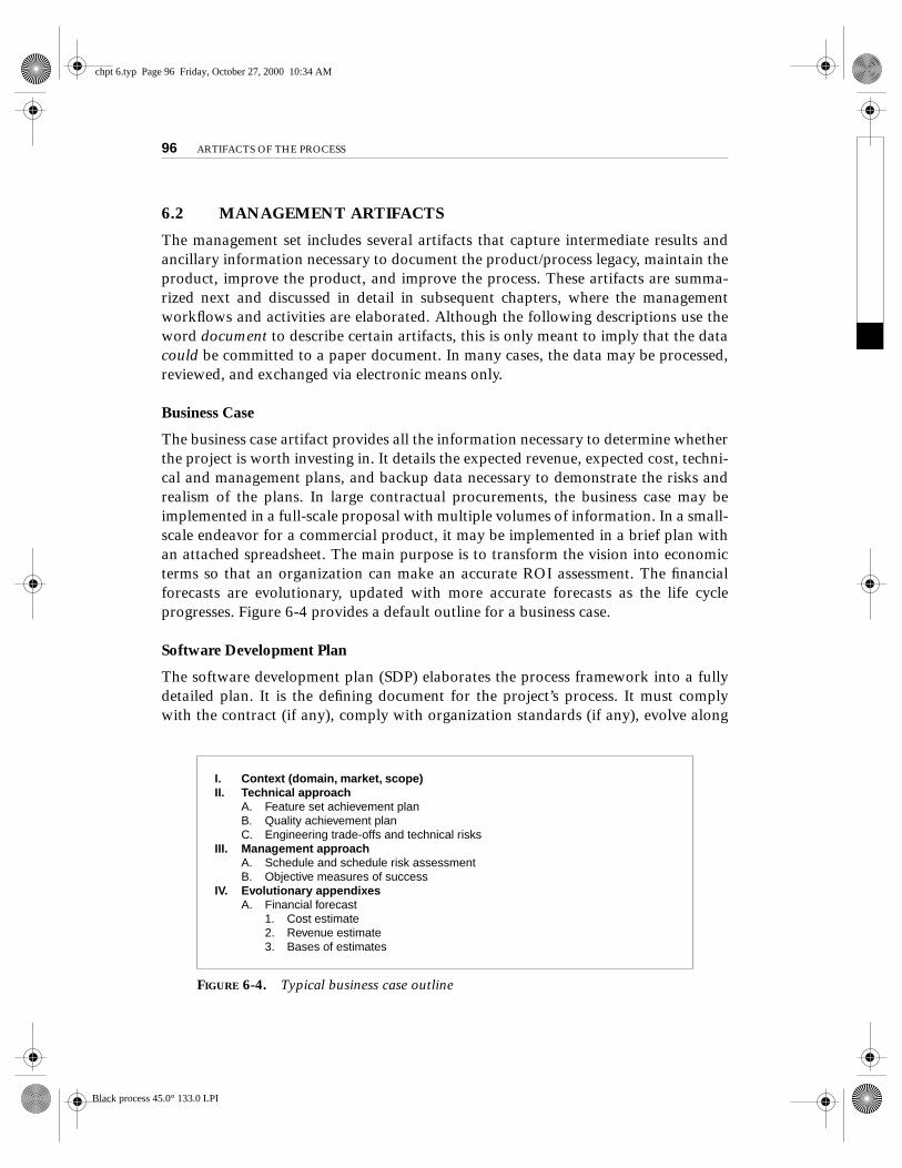
The business case artifact provides all the information necessary to determine whetherthe project is worth investing in. It details the expected revenue, expected cost, techni-cal and management plans, and backup data necessary to demonstrate the risks andrealism of the plans. In large contractual procurements, the business case may beimplemented in a full-scale proposal with multiple volumes of information. In a small-scale endeavor for a commercial product, it may be implemented in a brief plan withan attached spreadsheet. The main purpose is to transform the vision into economicterms so that an organization can make an accurate ROI assessment. The financialforecasts are evolutionary, updated with more accurate forecasts as the life cycleprogresses. Figure 6-4 provides a default outline for a business case.
Software Development Plan
The software development plan (SDP) elaborates the process framework into a fullydetailed plan. It is the defining document for the project’s process. It must complywith the contract (if any), comply with organization standards (if any), evolve along
FIGURE 6-4. Typical business case outline
I. Context (domain, market, scope)II. Technical approach
A. Feature set achievement planB. Quality achievement planC. Engineering trade-offs and technical risks
III. Management approachA. Schedule and schedule risk assessmentB. Objective measures of success
IV. Evolutionary appendixesA. Financial forecast
1. Cost estimate2. Revenue estimate3. Bases of estimates
chpt 6.typ Page 96 Friday, October 27, 2000 10:34 AM
Black process 45.0° 133.0 LPI

6.2 MANAGEMENT ARTIFACTS
97
with the design and requirements, and be used consistently across all subordinateorganizations doing software development. Two indications of a useful SDP are peri-odic updating (it is not stagnant shelfware) and understanding and acceptance bymanagers and practitioners alike. Figure 6-5 provides a default outline for a softwaredevelopment plan.
Work Breakdown Structure
A work breakdown structure (WBS) is the vehicle for budgeting and collecting costs.To monitor and control a project’s financial performance, the software project man-ager must have insight into project costs and how they are expended. The structure ofcost accountability is a serious project planning constraint. Lessons learned in numer-ous less-than-successful projects have shown that if the WBS is structured improperly,it can drive the evolving design and product structure in the wrong direction. Aproject manager should not lay out lower levels of a WBS (thereby defining specificboundaries of accountability) until a commensurate level of stability in the productstructure is achieved. A functional breakdown in the WBS will result in a functionaldecomposition in the software. The concept of an evolutionary WBS is developed furtherin Chapter 10.
FIGURE 6-5. Typical software development plan outline
I. Context (scope, objectives)II. Software development process
A. Project primitives1. Life-cycle phases2. Artifacts3. Workflows4. Checkpoints
B. Major milestone scope and contentC. Process improvement procedures
III. Software engineering environmentA. Process automation (hardware and software resource configuration)B. Resource allocation procedures (sharing across organizations, security
access)IV. Software change management
A. Configuration control board plan and proceduresB. Software change order definitions and proceduresC. Configuration baseline definitions and procedures
V. Software assessmentA. Metrics collection and reporting proceduresB. Risk management procedures (risk identification, tracking, and resolution)C. Status assessment planD. Acceptance test plan
VI. Standards and proceduresA. Standards and procedures for technical artifacts
VII. Evolutionary appendixesA. Minor milestone scope and contentB. Human resources (organization, staffing plan, training plan)
chpt 6.typ Page 97 Friday, October 27, 2000 10:34 AM
Black process 45.0° 133.0 LPI
98
ARTIFACTS OF THE PROCESS
Software Change Order Database
Managing change is one of the fundamental primitives of an iterative developmentprocess. With greater change freedom, a project can iterate more productively. Thisflexibility increases the content, quality, and number of iterations that a project canachieve within a given schedule. Change freedom has been achieved in practicethrough automation, and today’s iterative development environments carry the bur-den of change management. Organizational processes that depend on manual changemanagement techniques have encountered major inefficiencies. Consequently, thechange management data have been elevated to a first-class management artifact thatis described as a database to instill the concept of a need for automation. Once soft-ware is placed in a controlled baseline, all changes must be formally tracked and man-aged. By automating data entry and maintaining change records on-line, most of thechange management bureaucracy and metrics collection and reporting activities canbe automated. Software change orders are discussed in detail in Chapter 12.
Release Specifications
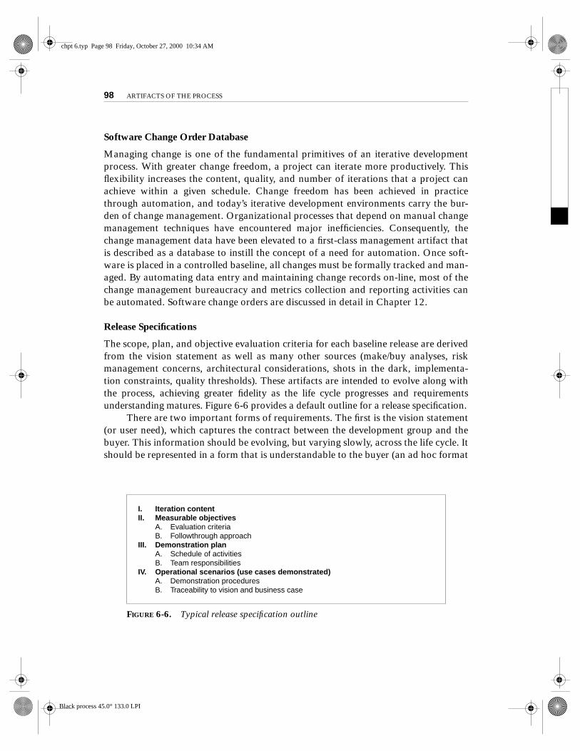
The scope, plan, and objective evaluation criteria for each baseline release are derivedfrom the vision statement as well as many other sources (make/buy analyses, riskmanagement concerns, architectural considerations, shots in the dark, implementa-tion constraints, quality thresholds). These artifacts are intended to evolve along withthe process, achieving greater fidelity as the life cycle progresses and requirementsunderstanding matures. Figure 6-6 provides a default outline for a release specification.
There are two important forms of requirements. The first is the vision statement(or user need), which captures the contract between the development group and thebuyer. This information should be evolving, but varying slowly, across the life cycle. Itshould be represented in a form that is understandable to the buyer (an ad hoc format
FIGURE 6-6. Typical release specification outline
I. Iteration contentII. Measurable objectives
A. Evaluation criteriaB. Followthrough approach
III. Demonstration planA. Schedule of activitiesB. Team responsibilities
IV. Operational scenarios (use cases demonstrated)A. Demonstration proceduresB. Traceability to vision and business case
chpt 6.typ Page 98 Friday, October 27, 2000 10:34 AM
Black process 45.0° 133.0 LPI

6.2 MANAGEMENT ARTIFACTS
99
that may include text, mockups, use cases, spreadsheets, or other formats). A use casemodel in the vision statement context serves to capture the operational concept interms the user/buyer will understand.
Evaluation criteria, the second form of requirements contained in release specifi-cations, are transient snapshots of objectives for a given intermediate life-cycle mile-stone. Evaluation criteria in release specifications are defined as management artifactsrather than as part of the requirements set. They are derived from the vision statementas well as many other sources (make/buy analyses, risk management concerns, archi-tectural considerations, shots in the dark, implementation constraints, quality thresh-olds). These management-oriented requirements may be represented by use cases, usecase realizations, annotations on use cases, or structured text representations.
The system requirements (user/buyer concerns) are captured in the vision state-ment. Lower levels of requirements are driven by the process (organized by iterationrather than by lower level component) in the form of evaluation criteria (typicallycaptured by a set of use cases and other textually represented objectives). Thus, thelower level requirements can evolve as summarized in the following conceptual exam-ple for a relatively large project:
1. Inception iterations.
Typically, 10 to 20 evaluation criteria capture thedriving issues associated with the critical use cases that have an impact onarchitecture alternatives and the overall business case.
2. Elaboration iterations. These evaluation criteria (perhaps 50 or so), whendemonstrated against the candidate architecture, verify that the critical usecases and critical requirements of the vision statement can be met with lowrisk.
3. Construction iterations. These evaluation criteria (perhaps hundreds) asso-ciated with a meaningful set of use cases, when passed, constitute usefulsubsets of the product that can be transitioned to formal test or to alpha orbeta releases.
4. Transition iterations. This complete set of use cases and associated evalua-tion criteria (perhaps thousands) constitutes the acceptance test criteriaassociated with deploying a version into operation.
This process is naturally evolutionary and is loosely coupled to the actual designand architecture that evolves. In the end, 100% traceability becomes important, butintermediate activities and milestones are far less concerned with consistency andcompleteness than they were when the conventional approach to software develop-ment was used. Each iteration’s evaluation criteria are discarded once the milestone iscompleted; they are transient artifacts. A better version is created at each stage, so
chpt 6.typ Page 99 Friday, October 27, 2000 10:34 AM
Black process 45.0° 133.0 LPI

100
ARTIFACTS OF THE PROCESS
there is much conservation of content and lessons learned in each successive set ofevaluation criteria. Release specification artifacts and their inherent evaluation crite-ria are more concerned early on with ensuring that the highest risk issues are resolved.
Release Descriptions
Release description documents describe the results of each release, including perfor-mance against each of the evaluation criteria in the corresponding release specifica-tion. Release baselines should be accompanied by a release description document thatdescribes the evaluation criteria for that configuration baseline and provides substan-tiation (through demonstration, testing, inspection, or analysis) that each criterionhas been addressed in an acceptable manner. This document should also include ametrics summary that quantifies its quality in absolute and relative terms (comparedto the previous versions, if any). The results of a post-mortem review of any releasewould be documented here, including outstanding issues, recommendations for pro-cess and product improvement, trade-offs in addressing evaluation criteria, follow-upactions, and similar information. Figure 6-7 provides a default outline for a releasedescription.
Status Assessments
Status assessments provide periodic snapshots of project health and status, includingthe software project manager’s risk assessment, quality indicators, and managementindicators. Although the period may vary, the forcing function needs to persist. Theparamount objective of a good management process is to ensure that the expectationsof all stakeholders (contractor, customer, user, subcontractor) are synchronized andconsistent. The periodic status assessment documents provide the critical mechanismfor managing everyone’s expectations throughout the life cycle; for addressing, com-municating, and resolving management issues, technical issues, and project risks; and
FIGURE 6-7. Typical release description outline
I. ContextA. Release baseline contentB. Release metrics
II. Release notesA. Release-specific constraints or limitations
III. Assessment resultsA. Substantiation of passed evaluation criteriaB. Follow-up plans for failed evaluation criteriaC. Recommendations for next release
IV. Outstanding issuesA. Action itemsB. Post-mortem summary of lessons learned
chpt 6.typ Page 100 Friday, October 27, 2000 10:34 AM
Black process 45.0° 133.0 LPI

6.2 MANAGEMENT ARTIFACTS
101
for capturing project history. They are the periodic heartbeat for management atten-tion. Section 9.3 discusses status assessments in more detail.
Typical status assessments should include a review of resources, personnel staff-ing, financial data (cost and revenue), top 10 risks, technical progress (metrics snap-shots), major milestone plans and results, total project or product scope, action items,and follow-through. Continuous open communications with objective data deriveddirectly from on-going activities and evolving product configurations are mandatoryin any project.
Environment
An important emphasis of a modern approach is to define the development and main-tenance environment as a first-class artifact of the process. A robust, integrated devel-opment environment must support automation of the development process. Thisenvironment should include requirements management, visual modeling, documentautomation, host and target programming tools, automated regression testing, andcontinuous and integrated change management, and feature and defect tracking. Acommon theme from successful software projects is that they hire good people andprovide them with good tools to accomplish their jobs. Automation of the softwaredevelopment process provides payback in quality, the ability to estimate costs andschedules, and overall productivity using a smaller team. By allowing the designers totraverse quickly among development artifacts and easily keep the artifacts up-to-date,integrated toolsets play an increasingly important role in incremental and iterativedevelopment.
Deployment
A deployment document can take many forms. Depending on the project, it couldinclude several document subsets for transitioning the product into operationalstatus. In big contractual efforts in which the system is delivered to a separate mainte-nance organization, deployment artifacts may include computer system operationsmanuals, software installation manuals, plans and procedures for cutover (from alegacy system), site surveys, and so forth. For commercial software products, deploy-ment artifacts may include marketing plans, sales rollout kits, and training courses.
Management Artifact Sequences
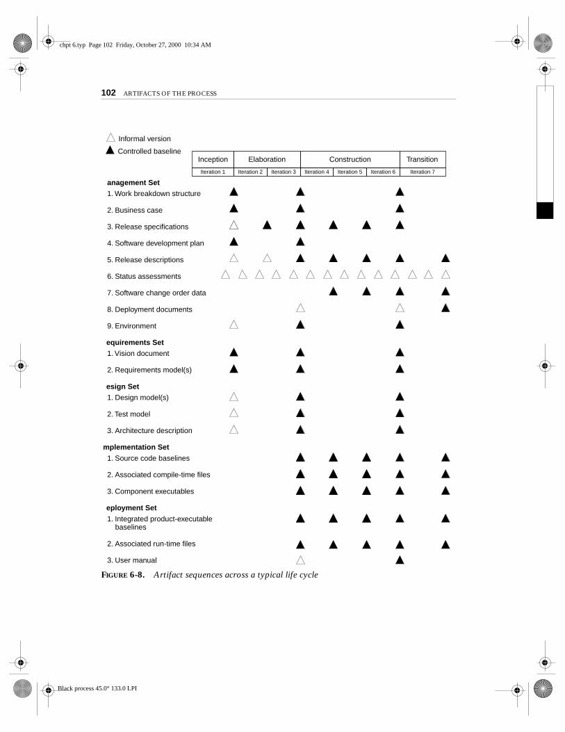
In each phase of the life cycle, new artifacts are produced and previously developedartifacts are updated to incorporate lessons learned and to capture further depth andbreadth of the solution. Some artifacts are updated at each major milestone, others ateach minor milestone. Figure 6-8 identifies a typical sequence of artifacts across thelife-cycle phases.
chpt 6.typ Page 101 Friday, October 27, 2000 10:34 AM
Black process 45.0° 133.0 LPI
102 ARTIFACTS OF THE PROCESS
anagement Set 1. Work breakdown structure
2. Business case
3. Release specifications
4. Software development plan
5. Release descriptions
6. Status assessments
7. Software change order data
8. Deployment documents
9. Environment
equirements Set 1. Vision document
2. Requirements model(s)
esign Set 1. Design model(s)
2. Test model
3. Architecture description
mplementation Set
1. Source code baselines
2. Associated compile-time files
3. Component executables
eployment Set
1. Integrated product-executable baselines
2. Associated run-time files
3. User manual
TransitionConstructionElaborationInception
Iteration 7Iteration 4Iteration 2Iteration 1 Iteration 3 Iteration 5 Iteration 6
Controlled baseline
Informal version
FIGURE 6-8. Artifact sequences across a typical life cycle
chpt 6.typ Page 102 Friday, October 27, 2000 10:34 AM
Black process 45.0° 133.0 LPI

6.3 ENGINEERING ARTIFACTS 103
6.3 ENGINEERING ARTIFACTS
Most of the engineering artifacts are captured in rigorous engineering notations suchas UML, programming languages, or executable machine codes. Because this book iswritten from a management perspective, it does not dwell on these artifacts. However,three engineering artifacts are explicitly intended for more general review, and theydeserve further elaboration.
Vision Document
The vision document provides a complete vision for the software system under devel-opment and supports the contract between the funding authority and the develop-ment organization. Whether the project is a huge military-standard development(whose vision could be a 300-page system specification) or a small, internally fundedcommercial product (whose vision might be a two-page white paper), every projectneeds a source for capturing the expectations among stakeholders. A project vision ismeant to be changeable as understanding evolves of the requirements, architecture,plans, and technology. A good vision document should change slowly. Figure 6-9 pro-vides a default outline for a vision document.
The vision document is written from the user’s perspective, focusing on theessential features of the system and acceptable levels of quality. The vision documentshould contain at least two appendixes. The first appendix should describe the opera-tional concept using use cases (a visual model and a separate artifact). The secondappendix should describe the change risks inherent in the vision statement, to guidedefensive design efforts.
The vision statement should include a description of what will be included aswell as those features considered but not included. It should also specify operationalcapacities (volumes, response times, accuracies), user profiles, and interoperationalinterfaces with entities outside the system boundary, where applicable. The visionshould not be defined only for the initial operating level; its likely evolution path
FIGURE 6-9. Typical vision document outline
I. Feature set descriptionA. Precedence and priority
II. Quality attributes and rangesIII. Required constraints
A. External interfacesIV. Evolutionary appendixes
A. Use cases1. Primary scenarios2. Acceptance criteria and tolerances
B. Desired freedoms (potential change scenarios)
chpt 6.typ Page 103 Friday, October 27, 2000 10:34 AM
Black process 45.0° 133.0 LPI

104 ARTIFACTS OF THE PROCESS
should be addressed so that there is a context for assessing design adaptability. Theoperational concept involves specifying the use cases and scenarios for nominal andoff-nominal usage. The use case representation provides a dynamic context for under-standing and refining the scope, for assessing the integrity of a design model, and fordeveloping acceptance test procedures. The vision document provides the contractualbasis for the requirements visible to the stakeholders.
Architecture Description
The architecture description provides an organized view of the software architectureunder development. It is extracted largely from the design model and includes viewsof the design, implementation, and deployment sets sufficient to understand how theoperational concept of the requirements set will be achieved. The breadth of the archi-tecture description will vary from project to project depending on many factors. Thearchitecture can be described using a subset of the design model or as an abstractionof the design model with supplementary material, or a combination of both. As exam-ples of these two forms of descriptions, consider the architecture of this book:
• A subset form could be satisfied by the table of contents. This descriptionof the architecture of the book is directly derivable from the book itself.
• An abstraction form could be satisfied by a “Cliffs Notes” treatment.(Cliffs Notes are condensed versions of classic books used as study guidesby some college students.) This format is an abstraction that is developedseparately and includes supplementary material that is not directly deriv-able from the evolving product.
The approach described in Section 7.2 allows an architecture description to be tai-lored to the specific needs of a project. Figure 6-10 provides a default outline for anarchitecture description.
Software User Manual
The software user manual provides the user with the reference documentation neces-sary to support the delivered software. Although content is highly variable acrossapplication domains, the user manual should include installation procedures, usageprocedures and guidance, operational constraints, and a user interface description, ata minimum. For software products with a user interface, this manual should be devel-oped early in the life cycle because it is a necessary mechanism for communicating andstabilizing an important subset of requirements. The user manual should be writtenby members of the test team, who are more likely to understand the user’s perspectivethan the development team. If the test team is responsible for the manual, it can begenerated in parallel with development and can be evolved early as a tangible and rel-
chpt 6.typ Page 104 Friday, October 27, 2000 10:34 AM
Black process 45.0° 133.0 LPI

6.4 PRAGMATIC ARTIFACTS 105
evant perspective of evaluation criteria. It also provides a necessary basis for test plansand test cases, and for construction of automated test suites.
6.4 PRAGMATIC ARTIFACTS
Conventional document-driven approaches squandered incredible amounts of engi-neering time on developing, polishing, formatting, reviewing, updating, and distribut-ing documents. Why? There are several reasons that documents became so importantto the process. First, there were no rigorous engineering methods or languages forrequirements specification or design. Consequently, paper documents with ad hoc textand graphical representations were the default format. Second, conventional lan-guages of implementation and deployment were extremely cryptic and highly unstruc-tured. To present the details of software structure and behavior to other interestedreviewers (testers, maintainers, managers), a more human-readable format wasneeded. Probably most important, software progress needed to be “credibly”assessed. Documents represented a tangible but misleading mechanism for demon-strating progress.
In some domains, document-driven approaches have degenerated over the past30 years into major obstacles to process improvement. The quality of the documentsbecame more important than the quality of the engineering information they repre-sented. And evaluating quality through human review of abstract descriptions is ahighly subjective process. Much effort was expended assessing single-dimensionalsurface issues, with very little attention devoted to the multidimensional issues thatdrive architecture qualities, such as performance and adaptability.
FIGURE 6-10. Typical architecture description outline
I. Architecture overviewA. ObjectivesB. ConstraintsC. Freedoms
II. Architecture viewsA. Design viewB. Process viewC. Component viewD. Deployment view
III. Architectural interactionsA. Operational concept under primary scenariosB. Operational concept under secondary scenariosC. Operational concept under anomalous conditions
IV. Architecture performanceV. Rationale, trade-offs, and other substantiation
chpt 6.typ Page 105 Friday, October 27, 2000 10:34 AM
Black process 45.0° 133.0 LPI

106 ARTIFACTS OF THE PROCESS
Document production cycles, review cycles, and update cycles also injected veryvisible and formal snapshots of progress into the schedule, thereby introducing moreschedule dependencies and synchronization points. For example, the following sce-nario was not uncommon on large defense projects: Spend a month preparing adesign document, deliver the document to the customer for review, wait a month toreceive comments back, then spend a month responding to comments and incorporat-ing changes. With many, many multiple-month document review cycles to be man-aged, scheduled, and synchronized, it is not surprising that many such projects endedup with five-year development life cycles. Lengthy and highly detailed documents,which were generally perceived to demonstrate more progress, resulted in prematureengineering details and increased scrap and rework later in the life cycle.
A more effective approach is to redirect this documentation effort to improvingthe rigor and understandability of the information source and allowing on-line reviewof the native information source by using smart browsing and navigation tools. Suchan approach can eliminate a huge, unproductive source of scrap and rework in theprocess and allow for continuous review by everyone who is directly concerned withthe evolving on-line artifacts.
This philosophy raises the following cultural issues:
• People want to review information but don’t understand the language ofthe artifact. Many interested reviewers of a particular artifact will resisthaving to learn the engineering language in which the artifact is written. Itis not uncommon to find people (such as veteran software managers, vet-eran quality assurance specialists, or an auditing authority from a regula-tory agency) who react as follows: “I’m not going to learn UML, but I wantto review the design of this software, so give me a separate description suchas some flowcharts and text that I can understand.” Would we respond to asimilar request by someone reviewing the engineering blueprints of a build-ing? No. We would require that the reviewer be knowledgeable in the engi-neering notation. We should stop patronizing audiences who resist treatingsoftware as an engineering discipline. These interested parties typically addcost and time to the process without adding value.
• People want to review the information but don’t have access to the tools. Itis not very common for the development organization to be fully tooled; itis extremely rare that the other stakeholders have any capability to reviewthe engineering artifacts on-line. Consequently, organizations are forced toexchange paper documents. Standardized formats (such as UML, spread-sheets, Visual Basic, C++, and Ada 95), visualization tools, and the Web arerapidly making it economically feasible for all stakeholders to exchangeinformation electronically. The approach to artifacts is one area in which
chpt 6.typ Page 106 Friday, October 27, 2000 10:34 AM
Black process 45.0° 133.0 LPI

6.4 PRAGMATIC ARTIFACTS 107
the optimal software development process can be polluted if the philoso-phy of the process is not accepted by the other stakeholders.
• Human-readable engineering artifacts should use rigorous notations thatare complete, consistent, and used in a self-documenting manner. Properlyspelled English words should be used for all identifiers and descriptions.Acronyms and abbreviations should be used only where they are well-accepted jargon in the context of the component’s usage. No matter whatlanguages or tools are used, there is no reason to abbreviate and encryptmodeling or programming language source identifiers. Saving keystrokesthrough abbreviation may simplify the artifact author’s job, but it intro-duces errors throughout the rest of the life cycle. Disallowing this practicewill pay off in both productivity and quality. Software is written only once,but it is read many times. Therefore, readability should be emphasized andthe use of proper English words should be required in all engineering arti-facts. This practice enables understandable representations, browseable for-mats (paperless review), more-rigorous notations, and reduced error rates.
• Useful documentation is self-defining: It is documentation that gets used.Above all, building self-documenting engineering artifacts gives the devel-opment organization the “right” to work solely in the engineering nota-tions and avoid separate documents to describe all the details of a model,component, or test procedure. If you find that information, and particu-larly a document, is getting produced but not used, eliminate it in favor ofwhatever is getting used to accomplish the intended purpose. Strive toimprove its self-documenting nature.
• Paper is tangible; electronic artifacts are too easy to change. One reasonsome stakeholders prefer paper documents is that once they are delivered,they are tangible, static, and persistent. On-line and Web-based artifactscan be changed easily and are viewed with more skepticism because of theirinherent volatility. Although electronic artifacts will and should be metwith healthy skepticism by many stakeholders, it is simply a matter of timebefore the whole world operates this way. The advantages are substantialand far-reaching across many domains. Rest assured that tools and envi-ronments will evolve to support change management, audit trails, elec-tronic signatures, and other advances in groupware so that electronicinterchange replaces paper.
It is extremely important that the information inherent in the artifact be empha-sized, not the paper on which it is written. Short documents are usually more usefulthan long ones. Software is the primary product; documentation is merely supportmaterial.
chpt 6.typ Page 107 Friday, October 27, 2000 10:34 AM
Black process 45.0° 133.0 LPI

chpt 6.typ Page 108 Friday, October 27, 2000 10:34 AM
Black process 45.0° 133.0 LPI


![6. UML Class Diagrams 6-1 Part 6: UML Class Diagramsusers.informatik.uni-halle.de/~brass/dd04/c6_umlcl.pdf · the artifacts of a software system. ... [Rational Software Corporation]](https://static.fdocuments.in/doc/165x107/5b146d657f8b9a257c8d1ccb/6-uml-class-diagrams-6-1-part-6-uml-class-brassdd04c6umlclpdf-the-artifacts.jpg)