
Articulated Object Reconstruction and Motion Capture from...
10
EUROGRAPHICS 2008 / G. Drettakis and R. Scopigno Volume 27 (2008), Number 2 (Guest Editors) © 2007 The Author(s) Journal compilation © 2007 The Eurographics Association and Blackwell Publishing Ltd. Published by Blackwell Publishing, 9600 Garsington Road, Oxford OX4 2DQ, UK and 350 Main Street, Malden, MA 02148, USA. Articulated Object Reconstruction and Markerless Motion Capture from Depth Video Yuri Pekelny and Craig Gotsman Center for Graphics and Geometric Computing Technion, Israel From depth images to skins to full skeletal 3D models Abstract We present an algorithm for acquiring the 3D surface geometry and motion of a dynamic piecewise-rigid object using a single depth video camera. The algorithm identifies and tracks the rigid components in each frame, while accumulating the geometric information acquired over time, possibly from different viewpoints. The algorithm also reconstructs the dynamic skeleton of the object, thus can be used for markerless motion capture. The acquired model can then be animated to novel poses. We show the results of the algorithm applied to synthetic and real depth video. Categories and Subject Descriptors (according to ACM CCS): I.3.5 [Computer Graphics]: Computational Geome- try and Object Modeling I.3.7 [Computer Graphics]: Three-Dimensional Graphics and Realism 1. Introduction Traditional 3D scanning applications involve only static subjects, and the main challenge in these applications is to produce an accurate digital model of the scene geome- try. Over the past decade, a multitude of algorithms have been proposed to address this problem, and by now it may be considered (almost) solved. Thus attention is shifting to dealing with dynamic scenes, i.e. ones in which the subjects are moving. Since the scene is dynamic, at first glance it may seem that the problem is not well-defined. What does scanning a scene in which the geometry is constantly changing mean ? What do we expect as the output of this process ? The problem is compounded by the fact that in order to capture any motion accurately, we must sense the scene at real-time rates, a technological challenge for the scan- ning device in its own right. To address the last challenge first, it seems that the most suitable sensor to use for dynamic scenes is the so-called depth video camera. Such a camera provides an image of the scene, where each pixel contains not only traditional intensity information, but also the geometric distance from the camera to the subject at that pixel. A number of commercial cameras generating this information at video rates have appeared over recent years [CVCM, 3DV, PS, VZS], and the state-of-the-art of the technologies in- volved is improving rapidly. Prices are also dropping, so we expect that depth video cameras will be available at reasonable cost within the next few years. The simplest version of the dynamic scene scanning problem is motion capture of a piecewise-rigid 3D sub- ject (such as a person). This means that as output we are not interested in the precise geometry of the subject, rather in the rough motion of a “skeleton” representing its rigid parts, of which there are usually just a few. Mo- tion capture is performed today using elaborate rigs in- volving markers placed on the subject, and it would be useful to have a device capable of markerless motion capture based only on depth cameras. This is the objec- tive of a number of commercial companies [3DV,PS] who are developing depth cameras for use as motion capture and gesture recognition devices in interactive consumer-level gaming applications. A more challenging version of the problem is full 3D scanning of dynamic piecewise-rigid 3D objects. The
Transcript of Articulated Object Reconstruction and Motion Capture from...

EUROGRAPHICS 2008 / G. Drettakis and R. Scopigno Volume 27 (2008), Number 2
(Guest Editors)
© 2007 The Author(s)
Journal compilation © 2007 The Eurographics Association and Blackwell Publishing Ltd.
Published by Blackwell Publishing, 9600 Garsington Road, Oxford OX4 2DQ, UK and
350 Main Street, Malden, MA 02148, USA.
Articulated Object Reconstruction and Markerless Motion
Capture from Depth Video
Yuri Pekelny and Craig Gotsman
Center for Graphics and Geometric Computing
Technion, Israel
From depth images to skins to full skeletal 3D models
Abstract
We present an algorithm for acquiring the 3D surface geometry and motion of a dynamic piecewise-rigid object
using a single depth video camera. The algorithm identifies and tracks the rigid components in each frame, while
accumulating the geometric information acquired over time, possibly from different viewpoints. The algorithm also
reconstructs the dynamic skeleton of the object, thus can be used for markerless motion capture. The acquired
model can then be animated to novel poses. We show the results of the algorithm applied to synthetic and real
depth video.
Categories and Subject Descriptors (according to ACM CCS): I.3.5 [Computer Graphics]: Computational Geome-
try and Object Modeling I.3.7 [Computer Graphics]: Three-Dimensional Graphics and Realism
1. Introduction
Traditional 3D scanning applications involve only static
subjects, and the main challenge in these applications is
to produce an accurate digital model of the scene geome-
try. Over the past decade, a multitude of algorithms have
been proposed to address this problem, and by now it
may be considered (almost) solved. Thus attention is
shifting to dealing with dynamic scenes, i.e. ones in
which the subjects are moving.
Since the scene is dynamic, at first glance it may seem
that the problem is not well-defined. What does scanning
a scene in which the geometry is constantly changing
mean ? What do we expect as the output of this process ?
The problem is compounded by the fact that in order to
capture any motion accurately, we must sense the scene
at real-time rates, a technological challenge for the scan-
ning device in its own right.
To address the last challenge first, it seems that the most
suitable sensor to use for dynamic scenes is the so-called
depth video camera. Such a camera provides an image of
the scene, where each pixel contains not only traditional
intensity information, but also the geometric distance
from the camera to the subject at that pixel. A number of
commercial cameras generating this information at video
rates have appeared over recent years [CVCM, 3DV, PS,
VZS], and the state-of-the-art of the technologies in-
volved is improving rapidly. Prices are also dropping, so
we expect that depth video cameras will be available at
reasonable cost within the next few years.
The simplest version of the dynamic scene scanning
problem is motion capture of a piecewise-rigid 3D sub-
ject (such as a person). This means that as output we are
not interested in the precise geometry of the subject,
rather in the rough motion of a “skeleton” representing
its rigid parts, of which there are usually just a few. Mo-
tion capture is performed today using elaborate rigs in-
volving markers placed on the subject, and it would be
useful to have a device capable of markerless motion
capture based only on depth cameras. This is the objec-
tive of a number of commercial companies [3DV,PS]
who are developing depth cameras for use as motion
capture and gesture recognition devices in interactive
consumer-level gaming applications.
A more challenging version of the problem is full 3D
scanning of dynamic piecewise-rigid 3D objects. The

Y. Pekelny & C. Gotsman / Articulated Object Reconstruction and Markerless Motion Capture from Depth Video
© 2007 The Author(s)
Journal compilation © 2007 The Eurographics Association and Blackwell Publishing Ltd.
desired output is not just a skeletal model of the subject,
rather a complete 3D model of the surface of each of the
rigid components, and a description of the motion of
each such component over time. It would be ideal if all
this could be computed in real time, but even offline
computation would be useful for many applications,
especially those in which it is impossible to prevent the
subject from moving during the scanning process.
The most challenging version of the problem is when the
objects in the scene are deforming over time in a non-
rigid manner. Here the description of the object motion is
more complicated, possibly even non-parametric.
This paper addresses the second question: scanning a
piecewise-rigid subject. The goal of the algorithm is to
recover the skeletal motion of the subject and to recon-
struct its surface geometry from a sequence of range
images captured by a single (possibly moving) depth
camera. The main issues are identification and tracking
of the rigid components and reconstructing their surfaces
despite partial occlusions present in each frame.
Since the system is markerless, it has no easily available
correspondence information between points in different
frames, thus it does not know which rigid component
each sampled point (pixel) belongs to, nor does it know
the rigid motion of any component between frames or the
relative (rigid) camera transformation between frames.
However, the temporal sampling rate is assumed to be
sufficiently high, so that the relative position of each
rigid component between each two consecutive frames is
close enough to provide a good initial estimate for the
classical Iterated Closest Point (ICP) registration algo-
rithm.
2. Previous Work
There are several algorithms in the literature for marker-
less motion capture from traditional video. Many of them
[MCA06, CBK03, TAM04] recover articulated object
motion from visual hull sequences, acquired from object
silhouettes. These algorithms require multiple synchro-
nized video cameras observing the subject from several
different directions, which incurs complications related
to temporal and spatial multi-camera calibration.
There are also several model-based approaches
[GWK05, RAPK06, BKM*04] capable of recovering
articulated object pose from a single depth image by
fitting it to a model. This, however, requires a very de-
tailed and calibrated model in order that a single depth
image suffice.
The algorithm proposed in [AKP*04] recovers a full 3D
model of the subject in addition to pose detection. This
algorithm also does not require markers, but each input
pose must be a complete surface mesh. Hence this algo-
rithm is inapplicable to depth video input.
We also aim to reconstruct a full 3D model of the sub-
ject. To register multiple components of an articulated
subject, we assume a piecewise-rigid skeletal structure.
A different approach was proposed in [MFO*07]. It
overcomes the registration problem by splitting the input
data into small almost-rigid pieces. This algorithm as-
sumes dense spatial and temporal sampling and performs
the registration using kinematic properties of the space-
time surface. An articulated version of this may be possi-
ble.
Several authors have proposed algorithms which recover
both the subject geometry and its motion. For example
[AFW*99] proposes an algorithm for articulated model
reconstruction. However the algorithm uses a pairwise
frame registration approach, hence becomes very ineffi-
cient when applied to a long input data sequence. The
authors also admit that the pairwise registration, as op-
posed to a more global approach, leads to suboptimal
results.
The authors of [KVD06] propose a model-based human
body motion tracking system called VooDoo. This sys-
tem models the human body as a collection of ten mov-
ing rigid cylinders (organized hierarchically), and tracks
their movement through time using the ICP registration
algorithm. It is necessary to manually resize the model
for each different human subject. VooDoo fails to give
good results using depth data input alone and requires
additional data from 2D tracking sensors to achieve good
results.
Another recent work [WJH*07] addresses a similar prob-
lem, but with a deformable subject. It performs iterative
reconstruction and optimization of the 4D structure as-
suming spatio-temporal smoothness. However the algo-
rithm is computationally heavy and it is not clear if it is
capable of reconstructing a complete 3D model of a de-
formable object from depth video.
To the best of our knowledge, ours is the first method
capable of reconstructing a complete 3D model of an
articulate object using a single depth video camera. This
is also the first markerless motion capture algorithm that
does not require a template mesh of the subject.
3. The Algorithm
3.1. Assumptions and outline
An articulated object consists of a set of connected rigid
components. It is customary to refer to the rigid compo-
nents as “bones”, and to the connection between two
bones as a “joint”. The actual 3D geometry of the surface
associated with the bone is called a “skin”. We make the
following assumptions on the input:
1. The motion of the subject is piecewise-rigid.
2. The combinatorial structure of the skeleton of the
subject is known, i.e n - the number of bones in the
subject - is given, and we are given a list of ID pairs
of connected bones.
3. All bones are (at least partially) visible in the first
frame, and a rough assignment (segmentation) of
image points to bones is given for this frame (see
Fig. 1).
4. During acquisition, the subject moves in such a way
that most of its surface points are visible to the cam-
era at some point in time.
Note that the information we assume about the skeleton
is purely combinatorial as opposed to geometric, namely,
we do not know anything about the length of bones or

Y. Pekelny & C. Gotsman / Articulated Object Reconstruction and Markerless Motion Capture from Depth Video
© 2007 The Author(s)
Journal compilation © 2007 The Eurographics Association and Blackwell Publishing Ltd.
the positions of joints. First frame segmentation is ac-
quired by a manual "coloring" process.
The algorithm tracks each bone of the subject almost
independently throughout the sequence. Each image
point is assigned a “bone index” – an integer in the set
{0,.., n}. The index 0 indicates that the point’s bone in-
dex is undecided, i.e. we have not been able to determine
which bone the image point belongs to with sufficient
confidence. These undecided points are typically in the
vicinity of joints (where more than one bone competes
for that point). The first objective is to accumulate over
time the skin geometry of each bone. The second objec-
tive is to track in some global coordinate system the mo-
tion of each bone over time.
Figure 1: Rough user segmentation of the first frame of
the real-world “Tow Truck” depth video sequence to
bones by painting the image pixels (left) with different
colors (right). Blue in right image means undecided bone
index.
The algorithm runs in several independent stages on each
depth image of the sequence. For each new image the
algorithm finds the new pose of each rigid bone by regis-
tering the accumulated skin geometry of the bone to the
new image points. The correctness of the registration is
verified by computing the coordinates of the joints of the
skeleton and checking that the skeleton remains con-
nected after applying the new transformations. The new
image points are then segmented into bones, namely a
bone index is assigned to each image point. A subset of
these new points covering regions previously not sam-
pled are then added to the accumulated skins. The fol-
lowing sections describe each stage of the algorithm in
detail and elaborate on the relations between them. Fig. 3
summarizes the algorithm.
3.2. Depth image preprocessing
Several components of our algorithm require normal
vectors of the input data points. To compute the normals
we construct a simple mesh from the depth image points
(pixels) and calculate the normals at vertices by area-
weighted average of the normals to neighboring faces.
This is a simple method which gives reasonable results if
the data is not too noisy. A more robust estimate could
use the normal to a least squares plane approximating a
few neighboring points, but this requires more computa-
tion. To construct a simple mesh we use the rectilinear
structure of the image grid. We generate all vertical,
horizontal and the shorter diagonal edges, while ignoring
those whose length is larger than four times the grid size.
After that we form triangles. This process also filters out
single points which are father that one grid unit from the
scanned point cloud, which are considered outliers.
3.3. Finding bone transformations
The algorithm processes each input frame separately in
chronological order. Each frame is analyzed based on the
results from the previous frames. During this process the
algorithm maintains two global data structures. One is
the accumulated 3D point clouds of the skins (each bone
is accumulated separately). The other is the set of all
rigid bone transformations from the first frame to all
other frames. From this set of transformations we can
find the relative transformation of any bone between any
two frames.
To find the relative rigid bone transformation for each
bone to a new input frame t, we register the skin of that
bone, accumulated so far, to the points of frame t using
the Iterated Closest Point (ICP) registration algorithm
[BM92] (note that we do not register in the opposite
direction). We use the bone’s transformation from the
first frame (where the reconstructed skin is accumulated)
to frame t-1 as the initial transformation for the ICP
process. If the sampling rate is dense enough this is an
excellent choice. The bones are registered in a hierar-
chical order, recursing (with BFS) through the skeletal
structure, starting from the root bone.
Figure 2: Skin geometry. 3D points are accumulated for
each bone separately (right). Each of these is later
meshed separately using a point cloud meshing algo-
rithm.
There are several cases where the ICP registration may
fail. For example, when the bone is occluded in the new
frame or when the overlap between the skin and the
points in the new frame is small. Our algorithm treats
both cases as occlusion and provides a number of me-
thods of detecting and recovering from ICP failure. For
each bone we start by trying to find the rigid transforma-
tion using ICP without any additional constraints. If we
fail, we find the joint locations between the current bone
and all other bones connected to it and repeat the ICP
process together with the joint constraint (see Section
3.6). If we fail again, the bone is considered occluded
and we approximate its transformation using skeleton
structure constraints, as described in Section 3.4.
The ICP algorithm is known to be sensitive to outliers.
To detect such outliers, we employ a number of heuris-
tics, similar to [RHHL02]. Corresponding pairs of points
(identified as such by the ICP nearest neighbor pairing)
of the following types are deemed outliers, hence ig-
nored.
1. Pairs whose distance from each other is larger than
a threshold.
2. Pairs whose angle between normals is larger than a
threshold.
Y. Pekelny & C. Gotsman / Articulated Object Reconstruction and Markerless Motion Capture from Depth Video
© 2007 The Author(s)
Journal compilation © 2007 The Eurographics Association and Blackwell Publishing Ltd.
3. Pairs whose target point lies on the input mesh
boundary.
To make the ICP algorithm more robust and accurate, we
use dynamic thresholds for items 1) and 2). The initial
distance threshold is 15x the image grid size and it de-
creases to 3x that after 5 iterations. The initial angle thre-
shold is 80°, decreasing to 20° after 4 iterations.
3.4. Treating occlusion
As mentioned above, we call a bone occluded if the ICP
registration algorithm failed. We have several ways to
detect when the registration fails:
1. The number of corresponding ICP point pairs falls
below a threshold.
2. The ICP algorithm does not converge quickly.
3. The resulting transformation does not satisfy the
constraint connecting this bone with its parent bone,
namely, the distance between current bone joint
transformed with the current bone transformation
and the same joint transformed with the connected
bone transformation is larger than a threshold.
Even if the bone is occluded, we would like to find an
approximate transformation that satisfies the skeleton
joint constraints, to keep the reconstructed skins con-
nected. We find an approximate transformation of the
occluded bone based on the transformations of the
neighboring bones and skeleton joints constraints:
1. If the occluded bone is connected to just one bone,
apply this neighbor’s relative transformation to the
occluded bone in the frame in which it is occluded.
2. If the occluded bone is connected to two bones, use
the rigid transformation that best fits both joint’s
movements and minimizes the relative rotation be-
tween the bones.
3. If the occluded bone is connected to more than two
bones, approximate its transformation by finding the
rigid transformation that best fits all joints move-
ment.
3.5. Bone assignment
Once we have found the relative transformation of all
bones between the first frame and a new frame t, we need
to segment the points in the new frame into bones. This
implies for each point, once segmented, a set of rigid
transformations from frame t to all previous frames 1..t-
1.
If the point p belongs to the skin of a bone b, then the
rigid transformation of b should translate p to the neigh-
borhood of b’s skin. To determine which bone p best
belongs to, we apply all possible bone transformations
(computed in the previous step) to p and calculate the
distance between the result and the nearest point of b’s
skin: db(p) = (1-α)dn(p)+αd(p) (typically α=0.1), where
dn(p) is the distance from p to the tangent plane at near-
est(p) – the local approximation of the reconstructed
surface, and d(p) is the distance from p to nearest(p). The
purpose of the second term is to reject far points that fall
near the tangent plane.
To decide which bone the point p belongs to among all
candidates, we use the following confidence measure:
' '
1 1/
( ) ( )b
b bonesb b
C pd p d p
,
Note that
1b
b
C p
After calculating confidences for all possible bone as-
signments we find bmax – the bone index which max-
imizes Cb(p). This is just the bone index which minimiz-
es db(p). However, we rely on this only if its confidence
is significantly larger than the confidences of the other
bones, namely, if Cbmax(p) > (typically =0.8) and
dbmax(p)< sampling density, then we assign p to bmax.
Otherwise p’s bone index remains undecided (=0) and
the point does not contribute to skin geometry and future
ICP registrations.
As mentioned in the previous section, some bones may
be occluded, thus their transformations are only an ap-
proximation based on skeleton connectivity constraints.
To avoid accumulating error due to these approxima-
tions, we consider as candidates only bones that are not
occluded.
3.6. Tracking the skeleton
A joint point u is a point connecting two bones b1 and b2.
Therefore transforming u from the first frame to any
other frame t with both bone transformations T1 and T2
should give the same result: T1(u) = T2(u). We seek a
joint u that satisfies this property for transformations to
all frames 2..t. Therefore, following [AKP*04], for each
pair of connected bones b1 and b2 we solve the following
minimization problem for u:
1 2
2 2
1
arg min ( ) ( )t
i i
b b
i
u T u T u u c
Where Tib is the transformation of bone b in frame i. c is
the centroid of a set of points in the vicinity of the joint,
namely, a small set of points of b1 close to b2 and vice
versa, in the first frame. Typically γ=0.1. The second
term stabilizes the solution in the cases where the first
term admits more than one possible solution. As before,
we ignore all transformation pairs that contain approx-
imate transformations for occluded bones.
To complete the skeleton construction we choose the
bone with the largest number of points in the first frame
to be the root bone and connect all other bones in a hie-
rarchical order.
3.7. Accumulating skin geometry
To reconstruct the skin geometry of a bone, we combine
the depth samples from different frames by registering
them in the coordinate system and the subject pose of the
first frame. This results in a set of points (and their nor-
mals) accumulated for each bone. The skin geometry
may then be reconstructed from this data, bone by bone,
by any point cloud meshing algorithm (e.g. [KBH06,
ACS*07]). See Fig. 2.
To register some point p from frame t into the coordinate
system of the first frame, we need to know p’s bone in-
dex and the rigid transformation of the bone between this
and the first frame. At each stage of the algorithm, when
we obtain this information for a point, it may contribute

Y. Pekelny & C. Gotsman / Articulated Object Reconstruction and Markerless Motion Capture from Depth Video
© 2007 The Author(s)
Journal compilation © 2007 The Eurographics Association and Blackwell Publishing Ltd.
to the reconstructed 3D model by applying the transfor-
mations. To reduce redundancy, thus limit the number of
points in the reconstruction without compromising the
skin completeness, we adopt only new points which are
not too close to the set of points accumulated so far. As
each sample point supposedly originates at the subject
surface, our measure of the proximity of a point p with
existing points on the subject is the distance from p to the
nearest point in the dataset – nearest(p) – projected onto
the tangent plane of nearest(p). We add a new point to
the skin geometry only if this distance is larger than a
threshold - typically half the grid size. Lowering this
threshold will increase the number of points contributing
to the surface model, but also increase the algorithm
runtime. The more frames sampled from different view-
points, the more complete the reconstructed geometry
becomes.
In practice, assignment of image points to the individual
skins is done only after all bones have been identified in
the image, as described in Section 3.5. The segmentation
process does not assign a bone index to every single
point - the points whose bone cannot be determined with
high confidence are left “undecided” and do not contri-
bute to the accumulated skin geometry.
1. Obtain from the user a rough segmentation of the
first frame and the skeleton connectivity informa-
tion
2. For t = 1..T do:
2.1. Calculate point normals and detect boundary
points (Section 3.2)
2.2. Find a relative transformation for each bone in
the reconstructed model to the new frame t (Sec-
tion 3.3)
2.3. Based on the transformations and the new frame
data, detect points with suspect bone assign-
ments in the reconstructed model and remove
them (Section 3.8)
2.4. Assign bone indices to points in the new frame t
(Section 3.5)
2.5. Find joint locations based on all bone transfor-
mations from frame 1 to frames 2..t (Section 3.6)
2.6. Add points from frame t to regions of the skins
not yet covered (Section 3.7)
3. Apply meshing algorithm to the accumulated skin
of each bone (e.g. [KBH06])
Figure 3: The reconstruction algorithm.
3.8. Filtering skin geometry
Bone skins are reconstructed by accumulating 3D points
which are assigned to bones that provide the best regis-
tration for them (as described in Section 3.5). When two
bones have similar transformations, it may be hard to
determine which bone is a better match. An erroneous
assignment may compound later in the process. To pre-
vent this we try to identify points assigned incorrectly
and remove them retroactively from the skins based on
the information in each new frame.
First we apply the bone transformations from the first
frame to the current frame for non-occluded bones. Then
we check each pair of connected (and unoccluded) bones
to see if they contain points representing two parallel
surfaces. More precisely, we look for pairs of points p
from b1 and nearest(p) from the neighbor b2, whose dis-
tance projected on the tangent plane of nearest(p) is
shorter than the distance projected along the normal di-
rection of nearest(p). All points satisfying this condition
are removed from the skin.
4. Experimental Results
4.1. Test cases
We have implemented our algorithm and applied it to
both real-world and synthetic depth video sequences.
Real data was captured by a Vialux Z-Snapper depth
camera (based on structured light technology) [VZS] for
two physical models: a toy robot and a toy tow truck,
consisting of 7 and 5 bones respectively. Both motion
sequences contain 90 frames, captured from arbitrary
viewpoints while the model was animated. The results
are shown in Figs. 6 and 7. The top row contains a subset
of the input depth video sequence. Since structured light
scanning technology is based on illuminating the subject
from an angle slightly different than that of the camera,
there are occlusions due to “self-shadows” from the illu-
mination angle, which can be quite significant at short
ranges. The second row shows the segmentation of the
depth images to no more than the number of components
(“bones”) specified by the user in the first frame. The
third row shows the accumulated bone skins in one static
model in the same poses as captured in the sequence,
after our processing. Due to occlusions in the input, or
undecided classification of image points, there are still
surface regions where data is missing, resulting in some
holes. The fourth row shows the same poses after the
bone geometries were meshed (as point clouds) to closed
manifold surfaces (each bone separately) using the algo-
rithm of [KBH06] (kindly provided by the authors). The
results are quite good despite the noise and occlusions in
the depth images.
While our algorithm is designed for subjects whose mo-
tion is piecewise-rigid, it is also applicable as an approx-
imation of the motion of deformable subjects in some
cases. Significant examples are models of skinned articu-
lated bodies, such as human and animals. We tested this
on a synthetic sequence (180 frames) of an articulated
model of a Beast containing 12 bones. The motion se-
quences for this model were a variation on the motion
taken from the CMU Graphics Lab Motion Capture Da-
tabase [CMU]. The inputs to our algorithm were the
captured Z-buffers of the rendered animations.
The results on this synthetic deformable model are de-
picted in Fig. 8. As expected, since the motion is not
truly piecewise-rigid, the results were not perfect. The
segmentation procedure, which feeds the rest of the
process, did not always classify the image points correct-
ly. An example is the rear end of the subject (colored
light blue in the figure) which was classified as part of
the upper right leg instead of the torso (colored purple).
This led to artifacts in the reconstruction, where that rear
end sometimes protrudes, giving the impression of a
“tail”.
Y. Pekelny & C. Gotsman / Articulated Object Reconstruction and Markerless Motion Capture from Depth Video
© 2007 The Author(s)
Journal compilation © 2007 The Eurographics Association and Blackwell Publishing Ltd.
4.2. Performance
Our algorithm was implemented in MATLAB, and tested
on a 2.8GHz Pentium D with 1GB of RAM. It was not
seriously optimized for performance. With an efficient
implementation, better hardware and some algorithm
improvements, we are confident that our algorithm can
be significantly accelerated, within range of real-time
performance, as other ICP-based reconstruction algo-
rithms [RHHL02]. The only part of our algorithm that we
did optimize was finding nearest neighbors among points
in 3D, since the algorithm spends a significant part of its
runtime on these types of operations during ICP. We
used the ANN C++ library [MA06], and yet still 63% of
the runtime is spent on nearest neighbor searching. Table
1 gives the performance summary for our three test se-
quences. The times quoted there do not include the pre-
processed normal computations.
Model #bones #frames points /frame
(average)
average
time/frame
(sec)
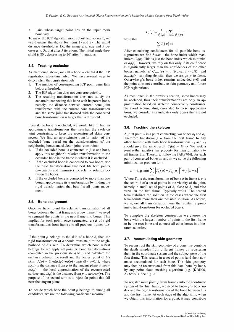
Truck 5 90 5,349 1.68
Robot 7 90 9,338 4.41
Beast 12 180 4,204 2.50
Table 1: Algorithm runtime performance.
4.3 The video
The video accompanying this paper demonstrates the
different stages of our scanning and motion capture pro-
cedure and shows some new animation sequences that
may be generated once the dynamic object is scanned.
The video may be found at
http://www.cs.technion.ac.il/~gotsman/mocap.mov
4.4 Limitations
A key component of our algorithm is the ability to detect
whether the inter-frame ICP registration succeeded or
not. This detection prevents incorrect segmentation,
which could be damaging. For some types of structured
data, this detection mechanism fails. For instance, the
model of a deforming human hand (see Fig. 4). The cy-
lindrical symmetry of the fingers confuses the ICP be-
cause there are many seemingly valid, but wrong, regis-
trations. So even if the camera rotates 360° around a
finger, the parts of the finger visible in each frame will
always be registered to each other in one region of the
finger, instead of completing the entire finger circumfe-
rence. Consequently, we generate both incorrect motion
capture and an incorrect 3D skin.
Figure 4: ICP failure to register a bone, due to cylin-
drical symmetry of the bone. The red skin remains in-
complete.
A possible solution to this problem is to supplement the
registration algorithm by using also the camera intensity
channel as a 4th data dimension. Another solution could
be replacing the ICP registration with any other algo-
rithm capable of registering two partial point clouds of a
rigid body.
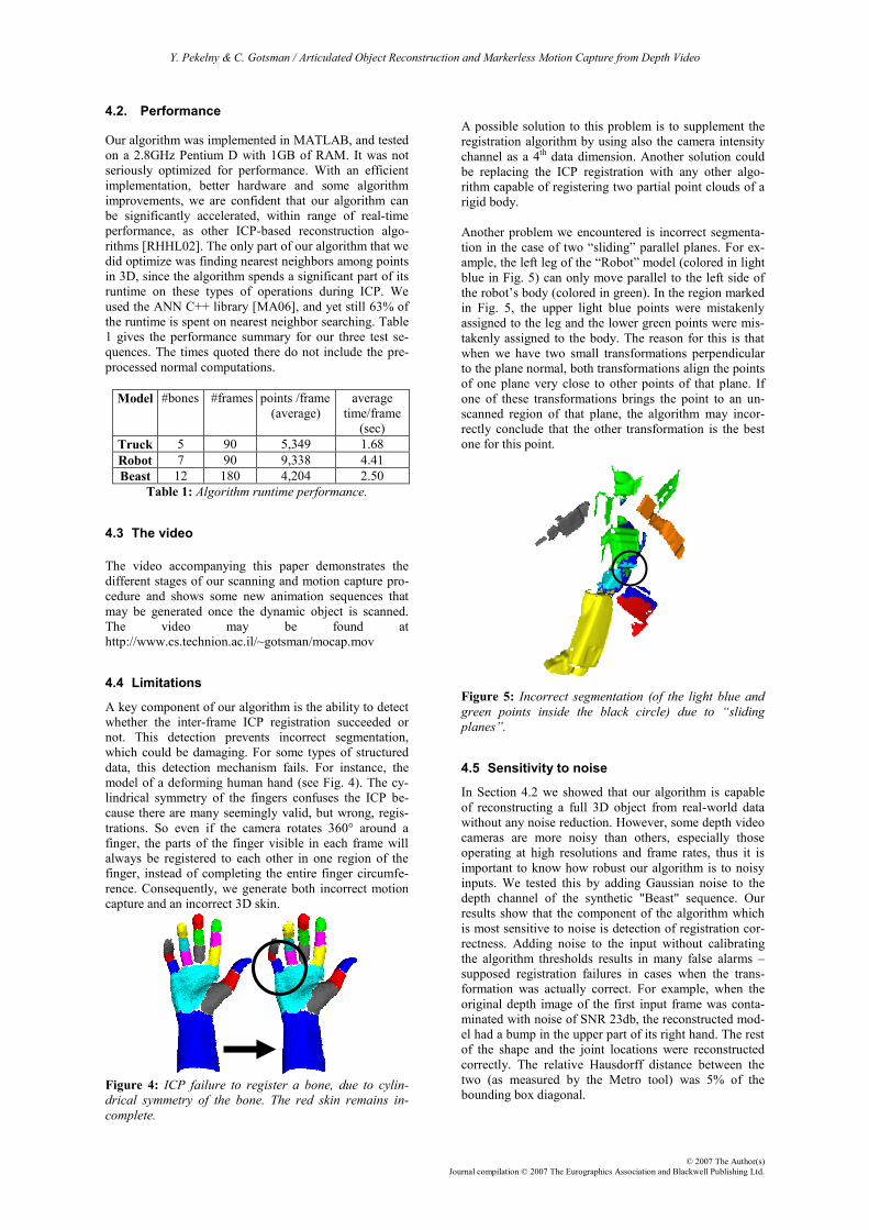
Another problem we encountered is incorrect segmenta-
tion in the case of two “sliding” parallel planes. For ex-
ample, the left leg of the “Robot” model (colored in light
blue in Fig. 5) can only move parallel to the left side of
the robot’s body (colored in green). In the region marked
in Fig. 5, the upper light blue points were mistakenly
assigned to the leg and the lower green points were mis-
takenly assigned to the body. The reason for this is that
when we have two small transformations perpendicular
to the plane normal, both transformations align the points
of one plane very close to other points of that plane. If
one of these transformations brings the point to an un-
scanned region of that plane, the algorithm may incor-
rectly conclude that the other transformation is the best
one for this point.
Figure 5: Incorrect segmentation (of the light blue and
green points inside the black circle) due to “sliding
planes”.
4.5 Sensitivity to noise
In Section 4.2 we showed that our algorithm is capable
of reconstructing a full 3D object from real-world data
without any noise reduction. However, some depth video
cameras are more noisy than others, especially those
operating at high resolutions and frame rates, thus it is
important to know how robust our algorithm is to noisy
inputs. We tested this by adding Gaussian noise to the
depth channel of the synthetic "Beast" sequence. Our
results show that the component of the algorithm which
is most sensitive to noise is detection of registration cor-
rectness. Adding noise to the input without calibrating
the algorithm thresholds results in many false alarms –
supposed registration failures in cases when the trans-
formation was actually correct. For example, when the
original depth image of the first input frame was conta-
minated with noise of SNR 23db, the reconstructed mod-
el had a bump in the upper part of its right hand. The rest
of the shape and the joint locations were reconstructed
correctly. The relative Hausdorff distance between the
two (as measured by the Metro tool) was 5% of the
bounding box diagonal.

Y. Pekelny & C. Gotsman / Articulated Object Reconstruction and Markerless Motion Capture from Depth Video
© 2007 The Author(s)
Journal compilation © 2007 The Eurographics Association and Blackwell Publishing Ltd.
5. Summary and Conclusion
We have presented an algorithm capable of reconstruct-
ing a full 3D model of a dynamic articulated subject from
a sequence of depth images taken by a single depth video
camera. The algorithm segments the input set of point
clouds to rigid components, detects rigid motions be-
tween the frames and reconstructs an articulated 3D
model in a single pass over the data. Another pass may
be performed in order to improve the joints consistency
during motion. The algorithm detects bone occlusion and
approximates skeleton-consistent motion for these oc-
cluded bones. In addition to 3D scanning, our algorithm
tracks the skeleton of the subject, thus can be used for
markerless motion capture over long sequences.
The Achilles heel of our algorithm is the requirement of
manual segmentation of the first frame and specification
of the combinatorial skeleton connectivity. We believe
that both these components can potentially be automated
using the approach described in [YP06] for automatic
learning of articulated object structure.
Another open issue is the usage of intensity information,
which is also provided by the depth video camera but
currently ignored. This information may improve the
registration step and help overcome some major algo-
rithm limitations (see Section 4.4). Of course, the intensi-
ty information can also be used for texture mapping sub-
ject appearance on the reconstructed 3D model.
Future versions of this work will improve the approxima-
tion in the case of a deforming subject which is not truly
piecewise-rigid. In the performance domain, our imple-
mentation currently runs offline after the data has been
captured. The holy grail is, of course, to optimize the
performance of the system so that it may run in real-time.
This will enable a variety of important applications in the
entertainment world.
Acknowledgements
Thanks to David Mount and Sunil Arya for making
available the ANN software package, to Michael Kazh-
dan for making available his software for 3D reconstruc-
tion from point clouds, and to Debbie Miller for record-
ing the sound track of the video.
This research was partially funded by European FP6 IST
NoE grant 506766 (AIM@SHAPE), the Israel Ministry
of Science, the State of Lower-Saxony and the Volkswa-
gen Foundation, Hannover, Germany.
References
[3DV] http://www.3dvsystems.com
[ACS*07] ALLIEZ P., COHEN-STEINER D., TONG Y., DE-
SBRUN M.: Voronoi-based variational reconstruction of
unoriented point sets. Proc. Eurographics Symp. on
Geometry Processing. (2007), pp. 39–48.
[AFW*99] ASHBROOK A. P., FISHER R. B., WERGHI N.,
ROBERTSON C.: Construction of articulated models
from range data. Proc. BMVC (1999), pp. 183–192.
[AKP*04] ANGUELOV D., KOLLER D., PANG H., SRINI-
VASAN P., THRUN S.: Recovering articulated object
models from 3D range data. Proc. Conference on Un-
certainty in Artificial Intelligence (2004), pp. 18–26.
[BKM*04] BRAY M., KOLLER-MEIER E., MÜLLER P.,
VAN GOOL L., SCHRAUDOLPH N.N.: 3D hand tracking
by rapid stochastic gradient descent using a skinning
model. In CVMP (2004), pp. 59–68.
[BM92] BESL P. J., MCKAY N. D.: A method for regis-
tration of 3D shapes. IEEE PAMI, 14:239–256, 1992.
[CBK03] CHEUNG G., BAKER S., KANADE T.: Shape-
from-silhouette for articulated objects and its use for
human body kinematics estimation and motion cap-
ture. Proc. CVPR (2003), pp.77–84.
[CMU] CMU Graphics Lab Motion Capture Database,
http://mocap.cs.cmu.edu
[CVCM] http://www.canesta.com
[GWK05] GREST D., WOETZEL J., KOCH R.: Nonlinear
body pose estimation from depth images. Proc. of
DAGM (2005), pp. 285–292.
[KBH06] KAZHDAN M., BOLITHO M., HOPPE H.: Poisson
surface reconstruction. Proc. Eurographics Symp. on
Geometry Processing. (2006), pp. 61–70.
[KVD06] KNOOP S., VACEK S. DILLMANN, R.: Sensor
fusion for 3D human body tracking with an articulated
3D body model. Proc. IEEE Conf. on Robotics and
Automation (2006), pp. 1686–1691.
[MA06] MOUNT D. M., ARYA S.: ANN: A library for
approximate nearest neighbor searching. Version
1.1.1, 2006, http://www.cs.umd.edu/~mount/ANN/
[MCA06] MÜNDERMANN L., CORAZZA S., ANDRIACCHI
T.: Markerless human motion capture through visual
hull and articulated ICP, Proc. NIPS Workshop 2006.
[MFO*07] MITRA N. J., FLORY S., OVSJANIKOV M., GEL-
FAND N., GUIBAS L., POTTMANN H.: Dynamic geome-
try registration. Proc. Eurographics Symp. on Geome-
try Processing (2007), pp. 173–182.
[PS] http://www.primesense.com
[RAPK06] RODGERS J., ANGUELOV D., PANG H.-C.,
KOLLER D.: Object pose detection in range scan data.
Proc. CVPR (2006), pp. 2445–2452.
[RHHL02] RUSINKIEWICZ S., HALL-HOLT O., LEVOY M.:
Real-time 3D model acquisition. Proc. SIGGRAPH
21, 3 (2002), pp. 438–446.
[TAM04] THEOBALT C., DE AGUILAR E., MAGNOR M.,
THEISEL H., SEIDEL H.-P.: Marker-free kinematic ske-
leton estimation from sequences of volume data. Proc.
ACM VRST (2004), pp. 57–64.
[VZS] http://www.vialux.de
[WJH*07] WAND M., JENKE P., HUANG Q., BOKELOH M.,
GUIBAS L., SCHILLING A.: Reconstruction of deforming
geometry from time-varying point clouds. Proc. Euro-
graphics Symp. on Geometry Processing (2007), pp.
49–58.
[YP06] YAN J., POLLEFEYS M.: Automatic kinematic
chain building from feature trajectories of articulated
objects. Proc. CVPR (2006), pp. 712–719.

Y. Pekelny & C. Gotsman / Articulated Object Reconstruction and Markerless Motion Capture from Depth Video
© 2007 The Author(s)
Journal compilation © 2007 The Eurographics Association and Blackwell Publishing Ltd.
Figure 6: Scanning the dynamic real-world Robot model containing 7 bones: (Top row) Some of the input depth frames
obtained by a Vialux depth video camera. Note the different camera viewpoints and model poses. (Second row) Segmenta-
tion of the input frames into bones. Dark blue regions are undecided. (Third row) Accumulated skin geometry in input pos-
es. Holes are present where the surface was occluded in all input frames. (Fourth row) Complete model in input poses after
skin reconstruction. (Bottom row) Reconstructed skeletons.

Y. Pekelny & C. Gotsman / Articulated Object Reconstruction and Markerless Motion Capture from Depth Video
© 2007 The Author(s)
Journal compilation © 2007 The Eurographics Association and Blackwell Publishing Ltd.
Figure 7: Scanning the dynamic real-world Tow-Truck model, consisting of 5 bones: (Top row) Some of the input depth frames
obtained by a Vialux depth video camera. Note the different camera viewpoints and model poses. (Second row) Segmentation of
the input frames into bones. Dark blue regions are undecided. (Third row) Accumulated skin geometry in input poses. Holes
are present where the surface was occluded in all input frames. (Fourth row) Complete model in input poses after skin recon-
struction. (Bottom row) Reconstructed skeletons.

Y. Pekelny & C. Gotsman / Articulated Object Reconstruction and Markerless Motion Capture from Depth Video
© 2007 The Author(s)
Journal compilation © 2007 The Eurographics Association and Blackwell Publishing Ltd.
Figure 8: “Scanning” the synthetic deformable Monster model, consisting of 12 “bones”: (Top row) Frames from the
synthetic animation sequence. (Second row) Input depth frames, as captured from the rendering z-buffer. (Third row)
Segmentation of the input frames into bones. Dark blue regions are undecided. Note the incorrect classification of the
rear end as part of the (light blue) right leg instead of the (purple) torso. (Fourth row) Accumulated skin geometry in
input poses. Holes are present where the surface was occluded in all input frames. (Bottom row) Complete model in
input poses after skin reconstruction.


![Computers & Graphics - Computer Science Department, Techniongotsman/AmendedPubl/Yin/halftone.pdf · tous in computer graphics [6,3]. The blue noise point distribution generation problem](https://static.fdocuments.in/doc/165x107/5f082be67e708231d420b1b8/computers-graphics-computer-science-department-gotsmanamendedpublyinhalftonepdf.jpg)