Article publié par le Laboratoire de Construction en Béton de … · When applied on top of...
13
Article publié par le Laboratoire de Construction en Béton de l'EPFL Paper published by the Structural Concrete Laboratory of EPFL Article publié par le Laboratoire de Construction en Béton de l'EPFL Paper published by the Structural Concrete Laboratory of EPFL Title: On the efficiency of flat slabs strengthening against punching using externally bonded fibre reinforced polymers Authors: Faria D. M. V., Einpaul J., Ramos A.P., Fernández Ruiz M., Muttoni A. Published in: Construction and Building Materials DOI 10.1016/j.conbuildmat.2014.09.084 Volume: Pages: Vol. 73 pp. 366-377 Country: Netherlands Year of publication: 2014 Type of publication: Peer reviewed journal article Please quote as: Faria D. M. V., Einpaul J., Ramos A.P., Fernández Ruiz M., Muttoni A., On the efficiency of flat slabs strengthening against punching using externally bonded fibre reinforced polymers, Construction and Building Materials, Vol. 73, Netherlands, 2014, pp. 366-377. [Faria14] Downloaded by infoscience (http://help-infoscience.epfl.ch/about) 128.178.209.23 on 17.11.2014 12:36
Transcript of Article publié par le Laboratoire de Construction en Béton de … · When applied on top of...
Article publié par le Laboratoire de Construction en Béton de l'EPFL Paper published by the Structural Concrete Laboratory of EPFL
Article publié par le Laboratoire de Construction en Béton de l'EPFL Paper published by the Structural Concrete Laboratory of EPFL
Title: On the efficiency of flat slabs strengthening against punching using externallybonded fibre reinforced polymers
Authors: Faria D. M. V., Einpaul J., Ramos A.P., Fernández Ruiz M., Muttoni A.
Published in: Construction and Building Materials
DOI 10.1016/j.conbuildmat.2014.09.084
Volume:Pages:
Vol. 73pp. 366-377
Country: Netherlands
Year of publication: 2014
Type of publication: Peer reviewed journal article
Please quote as: Faria D. M. V., Einpaul J., Ramos A.P., Fernández Ruiz M., Muttoni A., On theefficiency of flat slabs strengthening against punching using externally bondedfibre reinforced polymers, Construction and Building Materials, Vol. 73,Netherlands, 2014, pp. 366-377.
[Faria14] Downloaded by infoscience (http://help-infoscience.epfl.ch/about) 128.178.209.23 on 17.11.2014 12:36
Construction and Building Materials 73 (2014) 366–377
Contents lists available at ScienceDirect
Construction and Building Materials
journal homepage: www.elsevier .com/locate /conbui ldmat
On the efficiency of flat slabs strengthening against punching usingexternally bonded fibre reinforced polymers
http://dx.doi.org/10.1016/j.conbuildmat.2014.09.0840950-0618/� 2014 Elsevier Ltd. All rights reserved.
⇑ Corresponding author.E-mail addresses: [email protected] (D.M. V. Faria), [email protected]
(J. Einpaul), [email protected] (A.M. P. Ramos), [email protected](M. Fernández Ruiz), [email protected] (A. Muttoni).
Duarte M. V. Faria a,⇑, Jürgen Einpaul a, António M. P. Ramos b, Miguel Fernández Ruiz a, Aurelio Muttoni a
a Ecole Polytechnique Fédérale de Lausanne, CH-1015 Lausanne, Switzerlandb UNIC, Department of Civil Engineering, Faculdade de Ciências e Tecnologia, Universidade NOVA de Lisboa, 2829-516 Caparica, Portugal
h i g h l i g h t s
� FRP’s can be effectively used to strengthen existing flat slabs against punching shear.� The CSCT can be applied to predict the punching strength of strengthened slabs using FRP’s.� The strengthening efficiency is more pronounced in slabs with lower reinforcement ratio and larger column sizes.� The strengthening efficiency is less pronounced in actual continuous flat slabs.
a r t i c l e i n f o
Article history:Received 5 February 2014Received in revised form 27 August 2014Accepted 23 September 2014
Keywords:Flat slabsPunching shearFibre reinforced polymer strengtheningContinuous slabsInternal forces redistributionConstruction sequenceCritical Shear Crack Theory
a b s t r a c t
One possibility for strengthening existing flat slabs consists on gluing fibre reinforced polymers (FRPs) atthe concrete surface. When applied on top of slab–column connections, this technique allows increasingthe flexural stiffness and strength of the slab as well as its punching strength. Nevertheless, the higherpunching strength is associated to a reduction on the deformation capacity of the slab–column connec-tion, which can be detrimental for the overall behaviour of the structure (leading to a more brittle behav-iour of the system). Design approaches for this strengthening technique are usually based on empiricalformulas calibrated on the basis of the tests performed on isolated test specimens. However, some signif-icant topics as the reduction on the deformation capacity or the influence of the whole slab (accountingfor the reinforcement at mid-span) on the efficiency of the strengthening are neglected. In this paper, acritical review of this technique for strengthening against punching shear is investigated on the basis ofthe physical model proposed by the Critical Shear Crack Theory (CSCT). This approach allows taking intoaccount the amount, layout and mechanical behaviour of the bonded FRP’s in a consistent manner toestimate the punching strength and deformation capacity of strengthened slabs. The approach is firstused to predict the punching strength of available test data, showing a good agreement. Then, it is appliedin order to investigate strengthened continuous slabs, considering moment redistribution after concretecracking and reinforcement yielding. This latter study provides valuable information regarding thedifferences between the behaviour of isolated test specimens and real strengthened flat slabs. The resultsshow that empirical formulas calibrated on isolated specimens may overestimate the actual performanceof FRP’s strengthening. Finally, taking advantage of the physical model of the CSCT, the effect of theconstruction sequence on the punching shear strength is also evaluated, revealing the role of this issuewhich is also neglected in most empirical approaches.
� 2014 Elsevier Ltd. All rights reserved.
1. Introduction
Fibre Reinforcement Polymers (FRP) can be used as a techniqueto strengthen existing two way flat slabs against punching shear
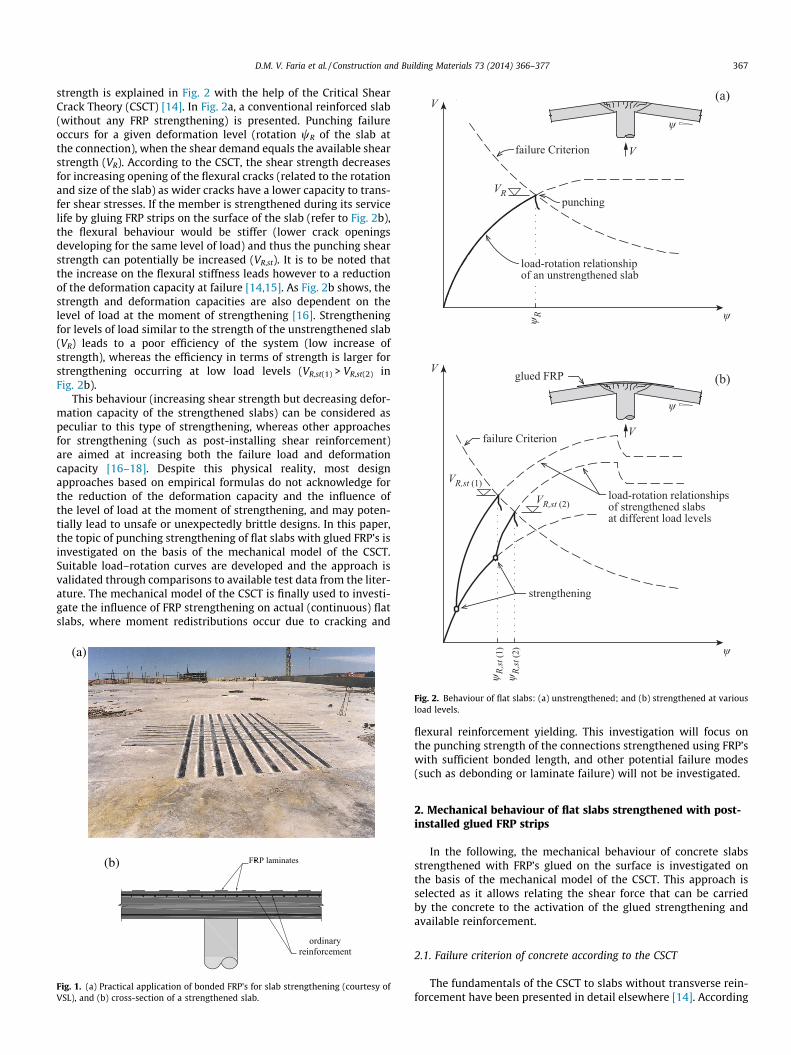
failures developing at slab–column connections [1–12]. For thispurpose, FRP strips are usually glued on the top surface of the slab(Fig. 1). Different potential failure modes can be governing formembers strengthened with FRP’s as described in Smith and Teng[13]: (1) FRP rupture, (2) crushing of the compressed concrete, (3)shear failure, (4) concrete cover separation, (5) plate end interfacialdebonding and (6) intermediate crack induced interfacial debond-ing. In this paper, the shear failure mode will be investigated indetail. The influence of FRP reinforcement on the punching shear
load-rotation relationships of strengthened slabs at different load levels
failure Criterion
V
V
ψ
ψ
ψ R
failure Criterion
punching
(a)
(b)glued FRP
V
V
ψ
load-rotation relationshipof an unstrengthened slab
strengthening
VR
VR,st (2)
VR,st (1)
D.M. V. Faria et al. / Construction and Building Materials 73 (2014) 366–377 367
strength is explained in Fig. 2 with the help of the Critical ShearCrack Theory (CSCT) [14]. In Fig. 2a, a conventional reinforced slab(without any FRP strengthening) is presented. Punching failureoccurs for a given deformation level (rotation wR of the slab atthe connection), when the shear demand equals the available shearstrength (VR). According to the CSCT, the shear strength decreasesfor increasing opening of the flexural cracks (related to the rotationand size of the slab) as wider cracks have a lower capacity to trans-fer shear stresses. If the member is strengthened during its servicelife by gluing FRP strips on the surface of the slab (refer to Fig. 2b),the flexural behaviour would be stiffer (lower crack openingsdeveloping for the same level of load) and thus the punching shearstrength can potentially be increased (VR,st). It is to be noted thatthe increase on the flexural stiffness leads however to a reductionof the deformation capacity at failure [14,15]. As Fig. 2b shows, thestrength and deformation capacities are also dependent on thelevel of load at the moment of strengthening [16]. Strengtheningfor levels of load similar to the strength of the unstrengthened slab(VR) leads to a poor efficiency of the system (low increase ofstrength), whereas the efficiency in terms of strength is larger forstrengthening occurring at low load levels (VR,st(1) > VR,st(2) inFig. 2b).
This behaviour (increasing shear strength but decreasing defor-mation capacity of the strengthened slabs) can be considered aspeculiar to this type of strengthening, whereas other approachesfor strengthening (such as post-installing shear reinforcement)are aimed at increasing both the failure load and deformationcapacity [16–18]. Despite this physical reality, most designapproaches based on empirical formulas do not acknowledge forthe reduction of the deformation capacity and the influence ofthe level of load at the moment of strengthening, and may poten-tially lead to unsafe or unexpectedly brittle designs. In this paper,the topic of punching strengthening of flat slabs with glued FRP’s isinvestigated on the basis of the mechanical model of the CSCT.Suitable load–rotation curves are developed and the approach isvalidated through comparisons to available test data from the liter-ature. The mechanical model of the CSCT is finally used to investi-gate the influence of FRP strengthening on actual (continuous) flatslabs, where moment redistributions occur due to cracking and
(a)
(b)
Fig. 1. (a) Practical application of bonded FRP’s for slab strengthening (courtesy ofVSL), and (b) cross-section of a strengthened slab.
ψ
ψ R,st
(1)
ψ R,st
(2)
Fig. 2. Behaviour of flat slabs: (a) unstrengthened; and (b) strengthened at variousload levels.
flexural reinforcement yielding. This investigation will focus onthe punching strength of the connections strengthened using FRP’swith sufficient bonded length, and other potential failure modes(such as debonding or laminate failure) will not be investigated.
2. Mechanical behaviour of flat slabs strengthened with post-installed glued FRP strips
In the following, the mechanical behaviour of concrete slabsstrengthened with FRP’s glued on the surface is investigated onthe basis of the mechanical model of the CSCT. This approach isselected as it allows relating the shear force that can be carriedby the concrete to the activation of the glued strengthening andavailable reinforcement.
2.1. Failure criterion of concrete according to the CSCT
The fundamentals of the CSCT to slabs without transverse rein-forcement have been presented in detail elsewhere [14]. According

−m
368 D.M. V. Faria et al. / Construction and Building Materials 73 (2014) 366–377
to this theory, the punching shear strength of a flat slab depends onthe opening and roughness of a critical shear crack that developsthrough the inclined compression strut carrying shear, refer toFig. 3. The opening of the critical shear crack (w) can be relatedto the rotation (w) of the slab around the slab–column connectiontimes the effective depth of the member: w / w�ds (where ds refersto the effective depth of the slab measured between the bottomcompressed face and the centroid of the top longitudinal reinforce-ment bars). According to this hypothesis, and by considering theroughness of the failure surface proportional to the maximumaggregate size, Muttoni [14] proposed the following failure crite-rion to calculate the shear strength of flat slabs:
VR ¼34
b0 � ds �ffiffiffiffif c
p1þ 15 � w�ds
dg0þdg
ð1Þ
where w is the slab rotation at failure, b0 is the length of the controlperimeter at a distance equal to ds/2 from the edge of the supportedarea, fc is the compressive strength of the concrete in (MPa), dg is themaximum aggregate size and dg0 is a reference aggregate size of16 mm. In Eq. (1), the effect of the slab slenderness and of theamount, stiffness and yield stress of the reinforcement is taken intoaccount in the slab rotation w. Size effect is accounted by theparameter ds in the denominator of Eq. (1).
In case a slab presents a number of layers of reinforcement (asfor slabs strengthened in flexure), the effective depth ds of Eq. (1) isto be replaced by an average effective depth (deq), which also mod-ifies the length of the control perimeter (beq at a distance of deq/2from the edge of the supported area):
VR ¼34
beq � deq �ffiffiffiffif c
p1þ 15 � w�deq
dg0þdg
ð2Þ
For brittle failures in punching (critical failures with lowrotation capacity), the flexural reinforcement remains mostly elas-tic. Thus, deq can be calculated as an average of ds and the effectivedepth of the strengthening reinforcement (dst), weighted upon thestiffness of each layer:
deq ¼ds � as � Es þ dst � ast � Est
as � Es þ ast � Est¼ ds �
1þ qstqs� Est
Es� dst
ds
� �2
1þ qstqs� Est
Es� dst
ds
� � ð3Þ
where as is the cross sectional area of the longitudinal reinforce-ment per unit width, ast is the cross sectional area of the strength-ening reinforcement per unit width, qst is the strengthening
Fig. 3. FRP debonding in the vicinity of the critical shear crack.
reinforcement ratio (=ast/dst); qs is the ordinary reinforcement ratio(=as/ds); Est and Es are the modulus of elasticity of the strengtheningreinforcement and of the ordinary reinforcement bars. It can benoted that Eq. (3) is only applicable when the strengtheningreinforcement crosses the critical shear crack r0 from the columnface (refer to radial FRP in Fig. 5), otherwise ds applies.
2.2. Load–rotation behaviour of isolated slab tests specimens
In order to calculate the punching shear capacity of a slab usingEq. (2), it is necessary to determine the load–rotation (V–w) rela-tionship of the slab, refer to Fig. 1a. In the following this will bedone by considering that no FRP debonding failure happens.Despite the fact that it will not be investigated hereafter, consider-ing bond failures of FRP’s is however possible as the model byMuttoni [14] allows considering the gradient of moments andstrains, thus enabling the implementation of FRP bond failuremodels from existing works [13,19,20] to two way slabs. In [14],it was shown that the load–rotation relationship can be suitablyestimated for reinforced concrete slabs considering a quadrilinearmoment–curvature (M–v) relationship for the cross-sections(Fig. 4, case (a)).
When considering slabs strengthened with glued FRP strips, theM–v law has to be modified to suitably account for the contribu-tion of the FRP strips. This leads to a larger number of potentialregimes and cases, refer to Fig. 4. The various regimes show a linearbehaviour that can be characterized as follows:
� EI0 – stiffness before cracking (stiffness of strengthening can beneglected).� EI1 – stiffness of the cracked unstrengthened section.� EI2 – stiffness of the cracked strengthened section.� EI3 – stiffness of the strengthened section after yielding of the
ordinary reinforcement bars.
Such moment–curvature laws can also take account of theconstruction sequence (that is, the load level at which thestrengthening is performed) leading to three different cases(Fig. 4, cases (b–d)). Appendix B of this paper describes a possibleapproach to obtain suitable moment–curvature relationships forreinforced concrete sections reinforced with glued FRP strips.
−χ
−m −mEI0
mcr
mR
my (c)
EI1
EI2
EI3
fracture due toFRP rupture ordebonding
(b)
(a)(c) (d)
(a) unstrengthened slab(b) strengthening before section cracking(c) strengthening before reinforcement yielding(d) strengthening after reinforcement yielding
my (b)
−χTS
Fig. 4. Moment curvature relationship of unstrengthened and strengthened RCsections.

(a)
(b)
(c)
(d)
Fig. 5. Assumed behaviour for axisymmetric slab: (a) unstrengthened slab; (b)strengthened slab; (c) forces in concrete and in reinforcement; and (d) internalforces acting on slab sector.
D.M. V. Faria et al. / Construction and Building Materials 73 (2014) 366–377 369
On the basis of given sectional moment–curvature, the load–rotation relationship of a slab (V–w) can be determined for anaxis-symmetric slab portion by accounting for equilibrium andkinematical conditions [14]. To do so, it is assumed that outsidethe critical shear crack (Fig. 5), the slab portion deforms followinga conical shape with a constant slab rotation (w), whereas itdeforms following a spherical shape within this region. The equi-librium conditions of the slab portion shown in Fig. 5d (conicalregion) lead to the following expression:
V � Du2p� rq � rc� �
¼ �mr � Du � r0 � Du �Z rs
r0
mtdr ð4Þ
where mr is the radial moment at r0 (computed using the M–v rela-tionships, hogging moment assumed to be negative) with vr ¼ �
wr0
.The tangential moment mt along the distance rs–r0 can also bedetermined using the corresponding M–v relationships as a func-tion of vt = �w/r. For reinforced slabs associated to quadri-linearmoment–curvature relationships, an analytical solution to Eq. (4)can be found [13]. For the very general case of a slab strengthened
with FRP strips at a given load level, a numerical integration of Eq.(4) is more suitable in order to determine the shear force developedfor a given level of rotation. This approach, thoroughly described inAppendix C of this paper, will be followed hereafter.
3. Analisis of available tests results on isolated slab specimens
3.1. Description of the selected test data
Several experimental programmes regarding the behaviour ofstrengthened flat slabs using bonded FRP strips have been carriedout in the last years. In the following, test results on symmetricalisolated slab specimens that reported all necessary mechanicaland geometrical properties to be compared to the previousmechanical model and with an effective depth ds larger than80 mm (to account for realistic dimensions in practice) wereselected [1,8,12]. Some other works [2–7,9–11] were not consid-ered as there was no information on the maximum aggregate sizeor the slabs were relatively thin. Table 1 presents the main charac-teristics of the tested slab specimens and the experimental andpredicted load capacity of each specimen. These series are brieflydescribed below.
Abdullah et al. [12] tested four slabs measuring 1800 �1800 � 150 mm together with a reference specimen used forcomparisons. One of the specimens was strengthened with non-prestressed CFRP laminates, whereas the other three hadprestressed laminates. It was shown that the load capacity of thenon-prestressed specimen increased considerably up to 43%. Thethree specimens with prestressed laminates failed due to debond-ing and will not be considered in this investigation. Suter and More-illon [8] tested four FRP strengthened slab specimens, along with acontrol specimen, measuring 2400 � 2400 � 200 mm. The aim ofthis series was to investigate on the serviceability behaviour andincrease of strength resulting from different strengthening materi-als, such as FRP’s (carbon, glass and aramid) laminates or tissues.According to the authors [8], the results showed that the increaseon strength is dependent on the strengthening type and layout,reaching a maximum of approximately 20%. Wang and Tan [1]tested four slab specimens, from which one was a reference slab.The specimens measured 1750 � 1750 � 120 mm. The adoptedstrengthening consisted of glued CFRP tissues. It was found thatthe strengthening slabs presented almost no improvement in theload capacity, but a stiffer behaviour was recorded. It can be notedthat, in some cases, the failure of the slabs was accompanied by deb-onding of the FRP’s. These debonding phenomena are probablyrelated to the relative vertical displacement associated to the coni-cal failure surface during the punching failure process (Fig. 3).
The efficiency as strengthening of the glued FRP’s reported inthe previous works is quite different (refer to Table 1). This seemsto be related to the ratio between the flexural stiffness of theunstrengthened slab and the strengthened one. For instance, Wangand Tan’s [1] slabs had a relatively high reinforcement ratio ofordinary steel (corresponding to a stiff and brittle behaviouraccording to Fig. 2). The strengthening, on the contrary, was consti-tuted by thin tissues, with relatively low axial stiffness. The overallinfluence of the strengthening on the flexural behaviour was thuslimited (limited increase on the stiffness of the slab) and thecorresponding increase on the punching failure load was thereforelimited. This observed behaviour is in agreement to the CSCTapproach.
3.2. Analysis of test data using the CSCT
The use and application of the CSCT to several cases has alreadybeen described in detail in previous works (punching with and
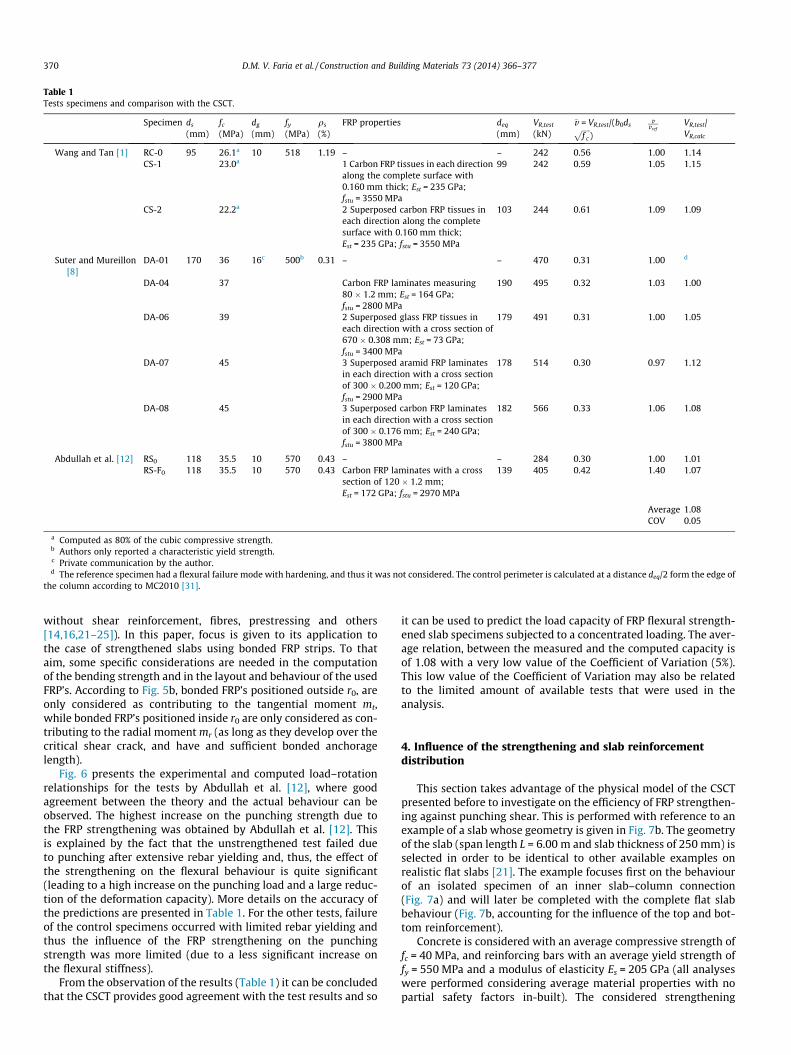
Table 1Tests specimens and comparison with the CSCT.
Specimen ds
(mm)fc
(MPa)dg
(mm)fy
(MPa)qs
(%)FRP properties deq
(mm)VR,test
(kN)�v = VR,test/(b0dsffiffiffiffiffi
f c
p)
�v�vref
VR,test/VR,calc
Wang and Tan [1] RC-0 95 26.1a 10 518 1.19 – – 242 0.56 1.00 1.14CS-1 23.0a 1 Carbon FRP tissues in each direction
along the complete surface with0.160 mm thick; Est = 235 GPa;fstu = 3550 MPa
99 242 0.59 1.05 1.15
CS-2 22.2a 2 Superposed carbon FRP tissues ineach direction along the completesurface with 0.160 mm thick;Est = 235 GPa; fstu = 3550 MPa
103 244 0.61 1.09 1.09
Suter and Mureillon[8]
DA-01 170 36 16c 500b 0.31 – – 470 0.31 1.00 d
DA-04 37 Carbon FRP laminates measuring80 � 1.2 mm; Est = 164 GPa;fstu = 2800 MPa
190 495 0.32 1.03 1.00
DA-06 39 2 Superposed glass FRP tissues ineach direction with a cross section of670 � 0.308 mm; Est = 73 GPa;fstu = 3400 MPa
179 491 0.31 1.00 1.05
DA-07 45 3 Superposed aramid FRP laminatesin each direction with a cross sectionof 300 � 0.200 mm; Est = 120 GPa;fstu = 2900 MPa
178 514 0.30 0.97 1.12
DA-08 45 3 Superposed carbon FRP laminatesin each direction with a cross sectionof 300 � 0.176 mm; Est = 240 GPa;fstu = 3800 MPa
182 566 0.33 1.06 1.08
Abdullah et al. [12] RS0 118 35.5 10 570 0.43 – – 284 0.30 1.00 1.01RS-F0 118 35.5 10 570 0.43 Carbon FRP laminates with a cross
section of 120 � 1.2 mm;Est = 172 GPa; fstu = 2970 MPa
139 405 0.42 1.40 1.07
Average 1.08COV 0.05
a Computed as 80% of the cubic compressive strength.b Authors only reported a characteristic yield strength.c Private communication by the author.d The reference specimen had a flexural failure mode with hardening, and thus it was not considered. The control perimeter is calculated at a distance deq/2 form the edge of
the column according to MC2010 [31].
370 D.M. V. Faria et al. / Construction and Building Materials 73 (2014) 366–377
without shear reinforcement, fibres, prestressing and others[14,16,21–25]). In this paper, focus is given to its application tothe case of strengthened slabs using bonded FRP strips. To thataim, some specific considerations are needed in the computationof the bending strength and in the layout and behaviour of the usedFRP’s. According to Fig. 5b, bonded FRP’s positioned outside r0, areonly considered as contributing to the tangential moment mt,while bonded FRP’s positioned inside r0 are only considered as con-tributing to the radial moment mr (as long as they develop over thecritical shear crack, and have and sufficient bonded anchoragelength).
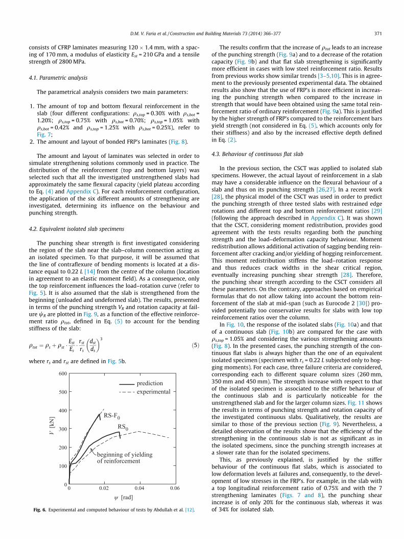
Fig. 6 presents the experimental and computed load–rotationrelationships for the tests by Abdullah et al. [12], where goodagreement between the theory and the actual behaviour can beobserved. The highest increase on the punching strength due tothe FRP strengthening was obtained by Abdullah et al. [12]. Thisis explained by the fact that the unstrengthened test failed dueto punching after extensive rebar yielding and, thus, the effect ofthe strengthening on the flexural behaviour is quite significant(leading to a high increase on the punching load and a large reduc-tion of the deformation capacity). More details on the accuracy ofthe predictions are presented in Table 1. For the other tests, failureof the control specimens occurred with limited rebar yielding andthus the influence of the FRP strengthening on the punchingstrength was more limited (due to a less significant increase onthe flexural stiffness).
From the observation of the results (Table 1) it can be concludedthat the CSCT provides good agreement with the test results and so
it can be used to predict the load capacity of FRP flexural strength-ened slab specimens subjected to a concentrated loading. The aver-age relation, between the measured and the computed capacity isof 1.08 with a very low value of the Coefficient of Variation (5%).This low value of the Coefficient of Variation may also be relatedto the limited amount of available tests that were used in theanalysis.
4. Influence of the strengthening and slab reinforcementdistribution
This section takes advantage of the physical model of the CSCTpresented before to investigate on the efficiency of FRP strengthen-ing against punching shear. This is performed with reference to anexample of a slab whose geometry is given in Fig. 7b. The geometryof the slab (span length L = 6.00 m and slab thickness of 250 mm) isselected in order to be identical to other available examples onrealistic flat slabs [21]. The example focuses first on the behaviourof an isolated specimen of an inner slab–column connection(Fig. 7a) and will later be completed with the complete flat slabbehaviour (Fig. 7b, accounting for the influence of the top and bot-tom reinforcement).
Concrete is considered with an average compressive strength offc = 40 MPa, and reinforcing bars with an average yield strength offy = 550 MPa and a modulus of elasticity Es = 205 GPa (all analyseswere performed considering average material properties with nopartial safety factors in-built). The considered strengthening
D.M. V. Faria et al. / Construction and Building Materials 73 (2014) 366–377 371
consists of CFRP laminates measuring 120 � 1.4 mm, with a spac-ing of 170 mm, a modulus of elasticity Est = 210 GPa and a tensilestrength of 2800 MPa.
4.1. Parametric analysis
The parametrical analysis considers two main parameters:
1. The amount of top and bottom flexural reinforcement in theslab (four different configurations: qs,top = 0.30% with qs,bot =1.20%; qs,top = 0.75% with qs,bot = 0.70%; qs,top = 1.05% withqs,bot = 0.42% and qs,top = 1.25% with qs,bot = 0.25%), refer toFig. 7;
2. The amount and layout of bonded FRP’s laminates (Fig. 8).
The amount and layout of laminates was selected in order tosimulate strengthening solutions commonly used in practice. Thedistribution of the reinforcement (top and bottom layers) wasselected such that all the investigated unstrengthened slabs hadapproximately the same flexural capacity (yield plateau accordingto Eq. (4) and Appendix C). For each reinforcement configuration,the application of the six different amounts of strengthening areinvestigated, determining its influence on the behaviour andpunching strength.
4.2. Equivalent isolated slab specimens
The punching shear strength is first investigated consideringthe region of the slab near the slab–column connection acting asan isolated specimen. To that purpose, it will be assumed thatthe line of contraflexure of bending moments is located at a dis-tance equal to 0.22 L [14] from the centre of the column (locationin agreement to an elastic moment field). As a consequence, onlythe top reinforcement influences the load–rotation curve (refer toFig. 5). It is also assumed that the slab is strengthened from thebeginning (unloaded and undeformed slab). The results, presentedin terms of the punching strength VR and rotation capacity at fail-ure wR are plotted in Fig. 9, as a function of the effective reinforce-ment ratio qtot, defined in Eq. (5) to account for the bendingstiffness of the slab:
qtot ¼ qs þ qst �Est
Es� rst
rs
dst
ds
� �3
ð5Þ
where rs and rst are defined in Fig. 5b.
0 0.02 0.04 0.060
100
200
300
400
500
600
RS0
RS-F0
ψ [rad]
V [k
N]
beginning of yieldingof reinforcement
experimentalprediction
Fig. 6. Experimental and computed behaviour of tests by Abdullah et al. [12].
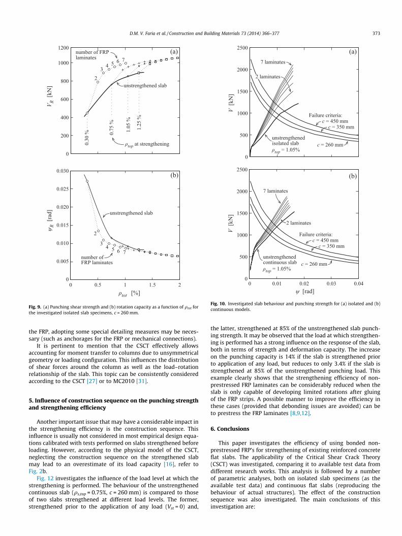
The results confirm that the increase of qtot leads to an increaseof the punching strength (Fig. 9a) and to a decrease of the rotationcapacity (Fig. 9b) and that flat slab strengthening is significantlymore efficient in cases with low steel reinforcement ratio. Resultsfrom previous works show similar trends [3–5,10]. This is in agree-ment to the previously presented experimental data. The obtainedresults also show that the use of FRP’s is more efficient in increas-ing the punching strength when compared to the increase instrength that would have been obtained using the same total rein-forcement ratio of ordinary reinforcement (Fig. 9a). This is justifiedby the higher strength of FRP’s compared to the reinforcement barsyield strength (not considered in Eq. (5), which accounts only fortheir stiffness) and also by the increased effective depth definedin Eq. (2).
4.3. Behaviour of continuous flat slab
In the previous section, the CSCT was applied to isolated slabspecimens. However, the actual layout of reinforcement in a slabmay have a considerable influence on the flexural behaviour of aslab and thus on its punching strength [26,27]. In a recent work[28], the physical model of the CSCT was used in order to predictthe punching strength of three tested slabs with restrained edgerotations and different top and bottom reinforcement ratios [29](following the approach described in Appendix C). It was shownthat the CSCT, considering moment redistribution, provides goodagreement with the tests results regarding both the punchingstrength and the load–deformation capacity behaviour. Momentredistribution allows additional activation of sagging bending rein-forcement after cracking and/or yielding of hogging reinforcement.This moment redistribution stiffens the load–rotation responseand thus reduces crack widths in the shear critical region,eventually increasing punching shear strength [28]. Therefore,the punching shear strength according to the CSCT considers allthese parameters. On the contrary, approaches based on empiricalformulas that do not allow taking into account the bottom rein-forcement of the slab at mid-span (such as Eurocode 2 [30]) pro-vided potentially too conservative results for slabs with low topreinforcement ratios over the column.
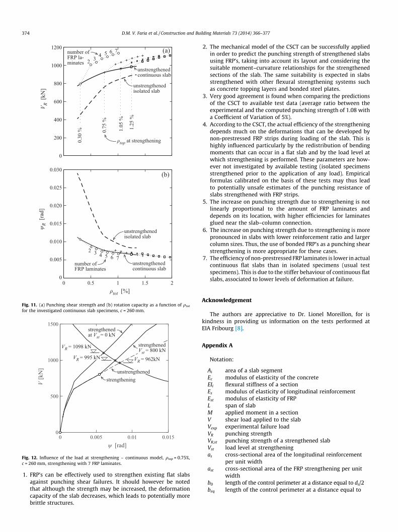
In Fig. 10, the response of the isolated slabs (Fig. 10a) and thatof a continuous slab (Fig. 10b) are compared for the case withqs,top = 1.05% and considering the various strengthening amounts(Fig. 8). In the presented cases, the punching strength of the con-tinuous flat slabs is always higher than the one of an equivalentisolated specimen (specimen with rs = 0.22 L subjected only to hog-ging moments). For each case, three failure criteria are considered,corresponding each to different square column sizes (260 mm,350 mm and 450 mm). The strength increase with respect to thatof the isolated specimen is associated to the stiffer behaviour ofthe continuous slab and is particularly noticeable for theunstrengthened slab and for the larger column sizes. Fig. 11 showsthe results in terms of punching strength and rotation capacity ofthe investigated continuous slabs. Qualitatively, the results aresimilar to those of the previous section (Fig. 9). Nevertheless, adetailed observation of the results show that the efficiency of thestrengthening in the continuous slab is not as significant as inthe isolated specimens, since the punching strength increases ata slower rate than for the isolated specimens.
This, as previously explained, is justified by the stifferbehaviour of the continuous flat slabs, which is associated tolow deformation levels at failures and, consequently, to the devel-opment of low stresses in the FRP’s. For example, in the slab witha top longitudinal reinforcement ratio of 0.75% and with the 7strengthening laminates (Figs. 7 and 8), the punching shearincrease is of only 20% for the continuous slab, whereas it wasof 34% for isolated slab.

(a)
(b)
Fig. 7. Investigated members: (a) isolated specimen; and (b) continuous slab.
(a)
(b)
Fig. 8. Strengthening with FRP laminates, examples for: (a) two laminates and (b) seven laminates (dimensions in mm).
372 D.M. V. Faria et al. / Construction and Building Materials 73 (2014) 366–377
In Fig. 11b it may also be noted that, in most cases, there is aslight increase on the rotation capacity between the unstrength-ened and the strengthened specimens. This phenomenon is dueto the fact that the failure criterion is not the same for all slabs,since deq is increased by the strengthening. The results also showthat the increase on the punching strength is not linearly propor-tional to the increase of the amount of strengthening material,and that the most efficient FRP strips are those located close tothe column region. This is related to the strain developed in theFRP strengthening laminates (Eq. (6)), which depends on the slabrotation w but also on the distance to the column r [14]:
e ¼ wr� ðdst � xÞ ð6Þ
where e is the strain in the FRP laminates, r is the radial distancefrom the column axis and x is the depth of the compression zone.
Based on these results, it may be concluded that for slabsstrengthened with low reinforcement ratios or large column sizes(Fig. 10), the FRP strips develop higher strains and are moreefficient as strengthening technique. This positive aspect is never-theless associated to a negative one, related to a higher risk of deb-onding of the FRP. In these cases, depending on the level of strain of
number of FRPlaminates
ψ R[r
ad]
ρtot [%]
V R[k
N]
(a)
(b)
2
3 4 5 6 7
3
2
4 5 6 7
number ofFRP laminates
unstrengthened slab
unstrengthened slab
ρtop at strengthening0.30
% 0.75
%
1.05
%
1.25
%
0
200
400
600
800
1000
1200
0 0.5 1 1.5 20
0.005
0.010
0.015
0.020
0.025
0.030
Fig. 9. (a) Punching shear strength and (b) rotation capacity as a function of qtot forthe investigated isolated slab specimens, c = 260 mm.
7 laminates
2 laminates
0
500
1000
1500
2000
2500
Failure criteria:
unstrengthened continuous slabρtop = 1.05%
c = 450 mmc = 350 mm
c = 260 mm
0 0.01 0.02 0.03 0.04
0
500
1000
1500
2000
2500
V [k
N]
ψ [rad]
V [k
N]
(b)
(a)
unstrengthened isolated slabρtop = 1.05%
Failure criteria:c = 450 mm
c = 350 mm
c = 260 mm
7 laminates
2 laminates
Fig. 10. Investigated slab behaviour and punching strength for (a) isolated and (b)continuous models.
D.M. V. Faria et al. / Construction and Building Materials 73 (2014) 366–377 373
the FRP, adopting some special detailing measures may be neces-sary (such as anchorages for the FRP or mechanical connections).
It is pertinent to mention that the CSCT effectively allowsaccounting for moment transfer to columns due to unsymmetricalgeometry or loading configuration. This influences the distributionof shear forces around the column as well as the load–rotationrelationship of the slab. This topic can be consistently consideredaccording to the CSCT [27] or to MC2010 [31].
5. Influence of construction sequence on the punching strengthand strengthening efficiency
Another important issue that may have a considerable impact inthe strengthening efficiency is the construction sequence. Thisinfluence is usually not considered in most empirical design equa-tions calibrated with tests performed on slabs strengthened beforeloading. However, according to the physical model of the CSCT,neglecting the construction sequence on the strengthened slabmay lead to an overestimate of its load capacity [16], refer toFig. 2b.
Fig. 12 investigates the influence of the load level at which thestrengthening is performed. The behaviour of the unstrengthenedcontinuous slab (qs,top = 0.75%, c = 260 mm) is compared to thoseof two slabs strengthened at different load levels. The former,strengthened prior to the application of any load (Vst = 0) and,
the latter, strengthened at 85% of the unstrengthened slab punch-ing strength. It may be observed that the load at which strengthen-ing is performed has a strong influence on the response of the slab,both in terms of strength and deformation capacity. The increaseon the punching capacity is 14% if the slab is strengthened priorto application of any load, but reduces to only 3.4% if the slab isstrengthened at 85% of the unstrengthened punching load. Thisexample clearly shows that the strengthening efficiency of non-prestressed FRP laminates can be considerably reduced when theslab is only capable of developing limited rotations after gluingof the FRP strips. A possible manner to improve the efficiency inthese cases (provided that debonding issues are avoided) can beto prestress the FRP laminates [8,9,12].
6. Conclusions
This paper investigates the efficiency of using bonded non-prestressed FRP’s for strengthening of existing reinforced concreteflat slabs. The applicability of the Critical Shear Crack Theory(CSCT) was investigated, comparing it to available test data fromdifferent research works. This analysis is followed by a numberof parametric analyses, both on isolated slab specimens (as theavailable test data) and continuous flat slabs (reproducing thebehaviour of actual structures). The effect of the constructionsequence was also investigated. The main conclusions of thisinvestigation are:
number ofFRP la-minates
ψ R[r
ad]
ρtot [%]
V R[k
N]
(a)
(b)
2 3 4 5 6 7
324 5 6 7
number ofFRP laminates
unstrengthened continuous slab
unstrengthened continuous slab
unstrengthened isolated slab
unstrengthened isolated slab
ρtop at strengthening0.30
% 0.75
%
1.05
%
1.25
%
0
200
400
600
800
1000
1200
0 0.5 1 1.5 20
0.005
0.010
0.015
0.020
0.025
0.030
Fig. 11. (a) Punching shear strength and (b) rotation capacity as a function of qtot
for the investigated continuous slab specimens, c = 260 mm.
0 0.005 0.01 0.0150
500
1000
1500
ψ [rad]
V [k
N]
VR = 962kNVR = 995 kN
strengthenedat Vst = 0 kN
VR = 1098 kN strengthenedVst = 800 kN
unstrengthenedstrengthening
Fig. 12. Influence of the load at strengthening – continuous model, qtop = 0.75%,c = 260 mm, strengthening with 7 FRP laminates.
374 D.M. V. Faria et al. / Construction and Building Materials 73 (2014) 366–377
1. FRP’s can be effectively used to strengthen existing flat slabsagainst punching shear failures. It should however be notedthat although the strength may be increased, the deformationcapacity of the slab decreases, which leads to potentially morebrittle structures.
2. The mechanical model of the CSCT can be successfully appliedin order to predict the punching strength of strengthened slabsusing FRP’s, taking into account its layout and considering thesuitable moment–curvature relationships for the strengthenedsections of the slab. The same suitability is expected in slabsstrengthened with other flexural strengthening systems suchas concrete topping layers and bonded steel plates.
3. Very good agreement is found when comparing the predictionsof the CSCT to available test data (average ratio between theexperimental and the computed punching strength of 1.08 witha Coefficient of Variation of 5%).
4. According to the CSCT, the actual efficiency of the strengtheningdepends much on the deformations that can be developed bynon-prestressed FRP strips during loading of the slab. This ishighly influenced particularly by the redistribution of bendingmoments that can occur in a flat slab and by the load level atwhich strengthening is performed. These parameters are how-ever not investigated by available testing (isolated specimensstrengthened prior to the application of any load). Empiricalformulas calibrated on the basis of these tests may thus leadto potentially unsafe estimates of the punching resistance ofslabs strengthened with FRP strips.
5. The increase on punching strength due to strengthening is notlinearly proportional to the amount of FRP laminates anddepends on its location, with higher efficiencies for laminatesglued near the slab–column connection.
6. The increase on punching strength due to strengthening is morepronounced in slabs with lower reinforcement ratio and largercolumn sizes. Thus, the use of bonded FRP’s as a punching shearstrengthening is more appropriate for these cases.
7. The efficiency of non-prestressed FRP laminates is lower in actualcontinuous flat slabs than in isolated specimens (usual testspecimens). This is due to the stiffer behaviour of continuous flatslabs, associated to lower levels of deformation at failure.
Acknowledgement
The authors are appreciative to Dr. Lionel Moreillon, for iskindness in providing us information on the tests performed atEIA Fribourg [8].
Appendix A
Notation:
Ai
area of a slab segment Ec modulus of elasticity of the concrete EIi flexural stiffness of a section Es modulus of elasticity of longitudinal reinforcement Est modulus of elasticity of FRP L span of slab M applied moment in a section V shear load applied to the slab Vexp experimental failure load VR punching strength VR,st punching strength of a strengthened slab Vst load level at strengthening as cross-sectional area of the longitudinal reinforcementper unit width
ast cross-sectional area of the FRP strengthening per unitwidth
b0 length of the control perimeter at a distance equal to ds/2 beq length of the control perimeter at a distance equal to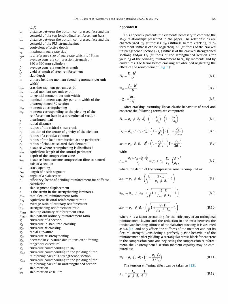
D.M. V. Faria et al. / Construction and Building Materials 73 (2014) 366–377 375
deq/2
ds distance between the bottom compressed face and thecentroid of the top longitudinal reinforcement bars
dst distance between the bottom compressed face and thecentroid of the FRP strengthening
deq equivalent effective depth dg maximum aggregate size dg0 is a reference size of aggregate which is 16 mm fc average concrete compression strength on150 � 300 mm cylinders
fct average concrete tensile strength fy yield strength of steel reinforcement h slab depth m unitary bending moment (bending moment per unitwidth)
mcr cracking moment per unit width mr radial moment per unit width mt tangential moment per unit width mR nominal moment capacity per unit width of theunstrengthened RC section
mst moment at strengthening my moment corresponding to the yielding of thereinforcement bars in a strengthened section
q distributed load r radial distance r0 radius of the critical shear crack ra location of the centre of gravity of the element rc radius of a circular column rq radius of the load introduction at the perimeter rs radius of circular isolated slab element rst distance where strengthening is distributed ueq equivalent length of the control perimeter x depth of the compression zone xel,i distance from extreme compression fibre to neutralaxis of a section
w crack opening Dri length of a slab segment Du angle of a slab sector b efficiency factor of bending reinforcement for stiffnesscalculation
d slab segment displacement e is the strain in the strengthening laminates qtot total flexural reinforcement ratio qeq equivalent flexural reinforcement ratio qs average ratio of ordinary reinforcement qst strengthening reinforcement ratio qs,top slab top ordinary reinforcement ratio qs,bot slab bottom ordinary reinforcement ratio v curvature of a section v1 curvature in stabilized cracking vcr curvature at cracking vr radial curvature vst curvature at strengthening vTS decrease in curvature due to tension stiffening vt tangential curvature vy curvature corresponding to mRvy,b
curvature corresponding to the yielding of thereinforcing bars of a strengthened sectionvy,u
curvature corresponding to the yielding of thereinforcing bars of an unstrengthened sectionw
slab rotation wR slab rotation at failureAppendix B
This appendix presents the elements necessary to compute theM–v relationships presented in the paper. The relationships arecharacterized by stiffnesses EI0 (stiffness before cracking, rein-forcement stiffness can be neglected), EI1 (stiffness of the crackedunstrengthened section), EI2 (stiffness of the cracked strengthenedsection) and/or EI3 (stiffness of the strengthened section afteryielding of the ordinary reinforcement bars), by moments and bycurvatures. The terms before cracking are obtained neglecting theeffect of the reinforcement (Fig. 5):
EI0 ¼Ec � h3
12ðB:1Þ
mcr ¼f ct � h
2
6ðB:2Þ
�vcr ¼mcr
EI0ðB:3Þ
After cracking, assuming linear-elastic behaviour of steel andconcrete the following terms are computed:
EI1 ¼ qs � b � Es � d3s � 1� c1
ds
� �� 1� c1
3ds
� �ðB:4Þ
EI2 ¼ qeq � b � Es � d3eq � 1� c2
deq
� �� 1� c2
3deq
� �ðB:5Þ
EI3 ¼ qst � b � Est � d3st � 1� c3
dst
� �� 1� c3
3dst
� �ðB:6Þ
with:
qeq ¼as þ ast � Est
Es� dst
ds
ds¼ qs þ qst �
Est
Es� dst
ds
� �2
ðB:7Þ
where the depth of the compressive zone is computed as:
xel;1 ¼ qs � b � ds �ffiffiffiffiffiffiffiffiffiffiffiffiffiffiffiffiffiffiffiffiffiffiffiffiffiffiffiffi1þ 2 � Ec
qs � b � Es
s� 1
!ðB:8Þ
xel;2 ¼ qeq � b � deq �ffiffiffiffiffiffiffiffiffiffiffiffiffiffiffiffiffiffiffiffiffiffiffiffiffiffiffiffiffi1þ 2 � Ec
qeq � b � Es
s� 1
!ðB:9Þ
xel;3 ¼ qst � b � dst �ffiffiffiffiffiffiffiffiffiffiffiffiffiffiffiffiffiffiffiffiffiffiffiffiffiffiffiffiffiffi1þ 2 � Ec
qst � b � Est
s� 1
!ðB:10Þ
where b is a factor accounting for the efficiency of an orthogonalreinforcement layout and the reduction in the ratio between thetorsion and bending stiffness of the slab after cracking. It is assumedas 0.6 [14] and only affects the stiffness of the member and not itsflexural strength. Considering a perfectly-plastic behaviour of thereinforcement after yielding, a rectangular stress block for concretein the compression zone and neglecting the compression reinforce-ment, the unstrengthened section moment capacity may be com-puted as:
mR ¼ qs � f y � d2s � 1�
qs � f y
2 � f c
� �ðB:11Þ
The tension stiffening effect can be taken as [13]:
vTS ¼f ct
q � b � Es� 16 � h ðB:12Þ
ri Δri
ri+1
χr,imr,i
χt,imt,i
χt,imt,i
χr,i+1mr,i+1
vi+1
vi
q
ri
ψi
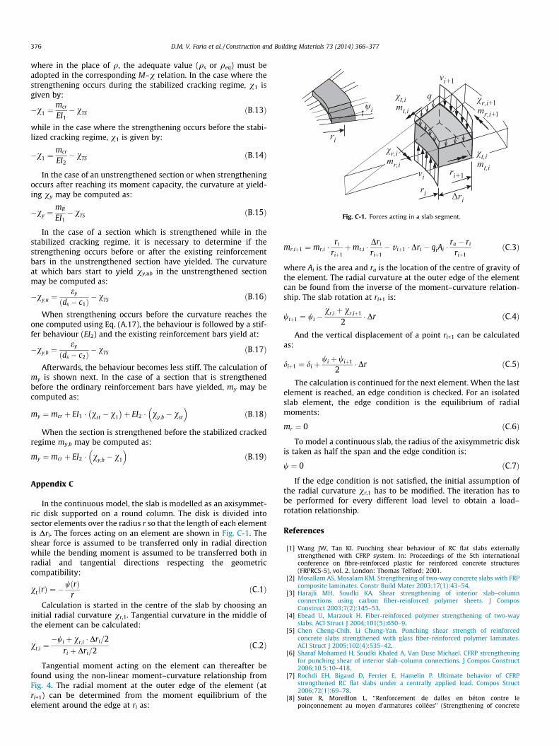
Fig. C-1. Forces acting in a slab segment.
376 D.M. V. Faria et al. / Construction and Building Materials 73 (2014) 366–377
where in the place of q, the adequate value (qs or qeq) must beadopted in the corresponding M–v relation. In the case where thestrengthening occurs during the stabilized cracking regime, v1 isgiven by:
�v1 ¼mcr
EI1� vTS ðB:13Þ
while in the case where the strengthening occurs before the stabi-lized cracking regime, v1 is given by:
�v1 ¼mcr
EI2� vTS ðB:14Þ
In the case of an unstrengthened section or when strengtheningoccurs after reaching its moment capacity, the curvature at yield-ing vy may be computed as:
�vy ¼mR
EI1� vTS ðB:15Þ
In the case of a section which is strengthened while in thestabilized cracking regime, it is necessary to determine if thestrengthening occurs before or after the existing reinforcementbars in the unstrengthened section have yielded. The curvatureat which bars start to yield vy,ub in the unstrengthened sectionmay be computed as:
�vy;u ¼ey
ds � c1ð Þ � vTS ðB:16Þ
When strengthening occurs before the curvature reaches theone computed using Eq. (A.17), the behaviour is followed by a stif-fer behaviour (EI2) and the existing reinforcement bars yield at:
�vy;b ¼ey
ds � c2ð Þ � vTS ðB:17Þ
Afterwards, the behaviour becomes less stiff. The calculation ofmy is shown next. In the case of a section that is strengthenedbefore the ordinary reinforcement bars have yielded, my may becomputed as:
my ¼ mcr þ EI1 � vst � v1
� �þ EI2 � vy;b � vst
� �ðB:18Þ
When the section is strengthened before the stabilized crackedregime my,b may be computed as:
my ¼ mcr þ EI2 � vy;b � v1
� �ðB:19Þ
Appendix C
In the continuous model, the slab is modelled as an axisymmet-ric disk supported on a round column. The disk is divided intosector elements over the radius r so that the length of each elementis Dri. The forces acting on an element are shown in Fig. C-1. Theshear force is assumed to be transferred only in radial directionwhile the bending moment is assumed to be transferred both inradial and tangential directions respecting the geometriccompatibility:
vtðrÞ ¼ �wðrÞ
rðC:1Þ
Calculation is started in the centre of the slab by choosing aninitial radial curvature vr,1. Tangential curvature in the middle ofthe element can be calculated:
vt;i ¼�wi þ vr;i � Dri=2
ri þ Dri=2ðC:2Þ
Tangential moment acting on the element can thereafter befound using the non-linear moment–curvature relationship fromFig. 4. The radial moment at the outer edge of the element (atri+1) can be determined from the moment equilibrium of theelement around the edge at ri as:
mr;iþ1 ¼ mr;i �ri
riþ1þmt;i �
Dri
riþ1� v iþ1 � Dri � qiAi �
ra � ri
riþ1ðC:3Þ
where Ai is the area and ra is the location of the centre of gravity ofthe element. The radial curvature at the outer edge of the elementcan be found from the inverse of the moment–curvature relation-ship. The slab rotation at ri+1 is:
wiþ1 ¼ wi �vr;i þ vr;iþ1
2� Dr ðC:4Þ
And the vertical displacement of a point ri+1 can be calculatedas:
diþ1 ¼ di þwi þ wiþ1
2� Dr ðC:5Þ
The calculation is continued for the next element. When the lastelement is reached, an edge condition is checked. For an isolatedslab element, the edge condition is the equilibrium of radialmoments:
mr ¼ 0 ðC:6Þ
To model a continuous slab, the radius of the axisymmetric diskis taken as half the span and the edge condition is:
w ¼ 0 ðC:7Þ
If the edge condition is not satisfied, the initial assumption ofthe radial curvature vr,1 has to be modified. The iteration has tobe performed for every different load level to obtain a load–rotation relationship.
References
[1] Wang JW, Tan KI. Punching shear behaviour of RC flat slabs externallystrengthened with CFRP system. In: Proceedings of the 5th internationalconference on fibre-reinforced plastic for reinforced concrete structures(FRPRCS-5), vol. 2. London: Thomas Telford; 2001.
[2] Mosallam AS, Mosalam KM. Strengthening of two-way concrete slabs with FRPcomposite laminates. Constr Build Mater 2003;17(1):43–54.
[3] Harajli MH, Soudki KA. Shear strengthening of interior slab–columnconnections using carbon fiber-reinforced polymer sheets. J ComposConstruct 2003;7(2):145–53.
[4] Ebead U, Marzouk H. Fiber-reinforced polymer strengthening of two-wayslabs. ACI Struct J 2004;101(5):650–9.
[5] Chen Cheng-Chih, Li Chung-Yan. Punching shear strength of reinforcedconcrete slabs strengthened with glass fiber-reinforced polymer laminates.ACI Struct J 2005;102(4):535–42.
[6] Sharaf Mohamed H, Soudki Khaled A, Van Duse Michael. CFRP strengtheningfor punching shear of interior slab–column connections. J Compos Construct2006;10.5:10–418.
[7] Rochdi EH, Bigaud D, Ferrier E, Hamelin P. Ultimate behavior of CFRPstrengthened RC flat slabs under a centrally applied load. Compos Struct2006;72(1):69–78.
[8] Suter R, Moreillon L. ‘‘Renforcement de dalles en béton contre lepoinçonnement au moyen d’armatures collées’’ (Strengthening of concrete

D.M. V. Faria et al. / Construction and Building Materials 73 (2014) 366–377 377
slabs to punching using bonded reinforcement). Test Report. EIA Fribourg;2007.
[9] Kim YJ, Longworth JM, Wight RG, Green MF. Flexure of two-way slabsstrengthened with prestressed or nonprestressed CFRP sheets. J ComposConstruct 2008;12(4):366–74.
[10] Esfahani MR, Kianoush MR, Moradi AR. Punching shear strength of interiorslab–column connections strengthened with carbon fiber reinforced polymersheets. Eng Struct 2009;31(7):1535–42.
[11] Farghaly AS, Ueda T. Prediction of punching shear strength of two-way slabsstrengthened externally with FRP sheets. J Compos Construct2010;15(2):181–93.
[12] Abdullah A, Bailey CG, Wu ZJ. Tests investigating the punching shear of acolumn–slab connection strengthened with non-prestressed or prestressedFRP plates. Constr Build Mater 2013;48:1134–44.
[13] Smith ST, Teng JG. FRP-strengthened RC beams. I: review of debondingstrength models. Eng Struct 2002;24(4):385–95.
[14] Muttoni A. Punching shear of reinforced concrete slabs without transversereinforcement. ACI Struct J 2008;105(4):440–50.
[15] Kinnunen S, Nylander H. Punching of concrete slabs without shearreinforcement. Trans R Inst Technol 1960;158(112):33. Stockholm, Sweden.
[16] Fernández Ruiz M, Muttoni A, Kunz J. Strengthening of flat slabs againstpunching shear using post-installed shear reinforcement. ACI Struct J2010;107(4):434–42.
[17] Inácio M, Pinho Ramos A, Faria D. Strengthening of flat slabs with transversereinforcement by introduction of steel bolts using different anchorageapproaches. Eng Struct 2012;44:63–77.
[18] Adetifa B, Polak MA. Retrofit of slab column interior connections using shearbolts. ACI Struct J 2005;102(2):238–74.
[19] Teng JG, Chen JF, Smith ST, Lam L. FRP strengthened RC structures. Wiley;2002. p. 266.
[20] Oller Ibars E, Cobo del Arco D, Marí Bernat AR. Design proposal to avoid peelingfailure in FRP-strengthened reinforced concrete beams. J Compos Construct2009;13(5):384–93.
[21] Muttoni A, Fernández Ruiz M, Bentz EC, Foster SJ, Sigrist V. Background to themodel code 2010 shear provisions – part II punching shear. Struct Concr2013;14(3):204–14.
[22] Fernández Ruiz M, Muttoni A. Applications of critical shear crack theory topunching of reinforced concrete slabs with transverse reinforcement. ACIStruct J 2009;106(4):485–94.
[23] Sagaseta J, Muttoni A, Fernández Ruiz M, Tassinari L. Non-axis-symmetricalpunching shear around internal columns of RC slabs without transversereinforcement’’. Mag Concr Res 2011;63(6):441–57.
[24] Maya LF, Fernández Ruiz M, Muttoni A, Foster SJ. Punching shear strength ofsteel fibre reinforced concrete slabs. Eng Struct 2012;40:83–94.
[25] Clément T, Ramos AP, Fernández Ruiz M, Muttoni A. Design for punching ofprestressed concrete slabs. Struct Concr 2013;14:157–67.
[26] Guandalini S. Poinçonnement symétrique des dalles en béton armé(Symmetric Punching of reinforced concrete slabs). École PolytéchinqueFédérale de Lausanne. PhD Thesis; 2005.
[27] Tassinari L. Poinçonnement non symétrique des dalles en béton armé (Non-symmetric punching of reinforced concrete slabs). École PolytéchinqueFédérale de Lausanne. PhD Thesis; 2011.
[28] Muttoni A, Fernández Ruiz M, Einpaul J. Punching strength of actual two-wayslabs. In: 4th Fib congress, Mumbai, India; 2014. p. 6.
[29] Choi JW, Kim JHJ. Experimental investigations on moment redistribution andpunching shear of flat plates. ACI Struct J 2012;109(3):329–37.
[30] Eurocode 2. Design of concrete structures—part 1–1: general rules and rulesfor buildings EN 1992-1-1; 2004.
[31] Fib Fédération international du béton. Model Code 2010. Final Draft. Lausanne,Switzerland; 2010. p. 653.