Article Optimization Simulation of the Light Aircraft’s ...
13
Article Optimization Simulation of the Light Aircraft’s Cockpit Made of Carbon Fiber Reinforced Composites Pu-Woei Chen * and Chia-Hung Liu Department of Aerospace Engineering, Tamkang University; New Taipei City 25137, Taiwan; [email protected] * Correspondence: [email protected]; Tel.: +886-2-86310403 Abstract: Due to the demands of personal travels and entertainments, light airplanes and small business aircrafts are developing rapidly. Light airplane structure is simple; however, it lacks crashworthiness design, especially the considerations on the impact of energy absorption. Therefore, in an event of accident, significant damage to passengers will be usually incurred. Airplanes made of composite materials structurally have high specific strength and good aerodynamic configuration. These materials have become the primary choice for new airplane development. This study mainly explores the topology optimization analysis of the light aircraft’s cockpit made of carbon fiber reinforced composites. This paper compares the compression amounts in the original models of composite material and aluminum alloy fuselages with the models after optimization during the crash-landing, in order to investigate the safety of fuselages made of different materials after structural optimization under the dynamic crashing. This study found that the energy absorbed by the aluminum alloy fuselage during crash-landing is still higher than that by the carbon fiber reinforced composites fuselage. On the other hand, the aluminum alloy fuselage after topology optimization could have an energy absorption capability enhanced by 40%, as compared to the that of the original model of aluminum alloy fuselage. Keywords: light aircraft; crashworthiness; topology optimization; composites materials; finite element analysis 1. Introduction Composite materials have been widely used in the major structural parts of large airplanes; in addition, fuselage of most of the newly developed small airplanes or light aircrafts is being made of all-composite structure. For example, the fuselage structures of Beechcraft Starship in the early 1989 and AerospoolWT9 Dynamic in the 2001 are manufactured using carbon fiber reinforced composites (CFRP). As classified in the general aviation (GA) category, the four- or five-seat Cirrus SR 22 with fuselage made of full composites received the European Aviation Safety Agency (EASA) certification in 2004. In 2013, the Ministry of Economy of Germany funded the research project on cabin safety for light aircraft (Safety Box) [1]. Its main objective was to encourage the crashworthiness design of light aircraft and provide a safe cabin in order to protect passengers from receiving serious injuries during a plane crash. Flight Design used the funding of this project to develop and manufacture the whole of a four-seat C4 airplane using carbon composites. Compared with the traditional airplane structure of aluminum alloy, the composite materials have many advantages, such as higher specific strength and stiffness, corrosion resistance capability, and good fatigue properties. Composite materials are usually classified as brittle materials, so the impact resistance or the capability of energy absorption during crash-landing requires further investigation to prove the material’s reliability. Crashworthiness usually refers to what degree an aircraft can maintain the structural integrity in order to protect the passengers from injury and provide adequate space to escape when the aircraft crash-lands onto the ground [2]. CFRP is used for more than 50% of the airplane structures of newly Preprints (www.preprints.org) | NOT PEER-REVIEWED | Posted: 31 March 2017 doi:10.20944/preprints201703.0233.v1
Transcript of Article Optimization Simulation of the Light Aircraft’s ...
Article
Optimization Simulation of the Light Aircraft’s Cockpit Made of Carbon Fiber Reinforced Composites Pu-Woei Chen * and Chia-Hung Liu
Department of Aerospace Engineering, Tamkang University; New Taipei City 25137, Taiwan; [email protected]
* Correspondence: [email protected]; Tel.: +886-2-86310403
Abstract: Due to the demands of personal travels and entertainments, light airplanes and small business aircrafts are developing rapidly. Light airplane structure is simple; however, it lacks crashworthiness design, especially the considerations on the impact of energy absorption. Therefore, in an event of accident, significant damage to passengers will be usually incurred. Airplanes made of composite materials structurally have high specific strength and good aerodynamic configuration. These materials have become the primary choice for new airplane development. This study mainly explores the topology optimization analysis of the light aircraft’s cockpit made of carbon fiber reinforced composites. This paper compares the compression amounts in the original models of composite material and aluminum alloy fuselages with the models after optimization during the crash-landing, in order to investigate the safety of fuselages made of different materials after structural optimization under the dynamic crashing. This study found that the energy absorbed by the aluminum alloy fuselage during crash-landing is still higher than that by the carbon fiber reinforced composites fuselage. On the other hand, the aluminum alloy fuselage after topology optimization could have an energy absorption capability enhanced by 40%, as compared to the that of the original model of aluminum alloy fuselage.
Keywords: light aircraft; crashworthiness; topology optimization; composites materials; finite element analysis
1. Introduction
Composite materials have been widely used in the major structural parts of large airplanes; in addition, fuselage of most of the newly developed small airplanes or light aircrafts is being made of all-composite structure. For example, the fuselage structures of Beechcraft Starship in the early 1989 and AerospoolWT9 Dynamic in the 2001 are manufactured using carbon fiber reinforced composites (CFRP). As classified in the general aviation (GA) category, the four- or five-seat Cirrus SR 22 with fuselage made of full composites received the European Aviation Safety Agency (EASA) certification in 2004. In 2013, the Ministry of Economy of Germany funded the research project on cabin safety for light aircraft (Safety Box) [1]. Its main objective was to encourage the crashworthiness design of light aircraft and provide a safe cabin in order to protect passengers from receiving serious injuries during a plane crash. Flight Design used the funding of this project to develop and manufacture the whole of a four-seat C4 airplane using carbon composites. Compared with the traditional airplane structure of aluminum alloy, the composite materials have many advantages, such as higher specific strength and stiffness, corrosion resistance capability, and good fatigue properties. Composite materials are usually classified as brittle materials, so the impact resistance or the capability of energy absorption during crash-landing requires further investigation to prove the material’s reliability. Crashworthiness usually refers to what degree an aircraft can maintain the structural integrity in order to protect the passengers from injury and provide adequate space to escape when the aircraft crash-lands onto the ground [2]. CFRP is used for more than 50% of the airplane structures of newly
Preprints (www.preprints.org) | NOT PEER-REVIEWED | Posted: 31 March 2017 doi:10.20944/preprints201703.0233.v1
2 of 13
developed Boeing 787 and Airbus 350. However, the ductility of carbon fiber is lower than those of glass fiber and polymer fiber commonly used on other structures; therefore, the compression amount of CFRP during colliding needs to be further investigated.
Since airplane design has involved the integration work of large and complex systems, its performance and constraints must be considered on the design; therefore, the Collaborative and Robust Engineering using Simulation Capability Enabled Next Design Optimization (CRESCENDO) project has been established in 2009 [3]. The project aims to complete the foundation of Behavioural Digital Aircraft (BDA) using simulation technology by 2020, whereby the optimization analysis technology of aerodynamics and structural coupling is one of the main objectives for the future development. On the design of A350 XWB (including the structural components such as the fuselage and wingbox), Airbus used optimization analysis software that can reduce the weight of the original design by 30% and increase the intensity by 30% through structural redistribution [4]. Composite materials can be used as airplane structural parts to reduce the consumption of metal parts during the processing, reduce the use of rivets, and provide an excellent aerodynamic configure; therefore, it is more suitable to use optimization simulation to achieve the aim of multidisciplinary design.
A total of 1,553 cases have been recorded on the civil aviation accident investigation statistics of National Transportation Safety Board (NTSB) in 2011; of these, GA was accounted for 1,469 cases [5]. Among the fatal accidents, GA was accounted for 92%, of which the accidents with single reciprocating engine airplanes were the most. According to the estimations by European Personal Air Transportation System (EU EPATS) [6], the number of flight trips for small airplanes will be reaching 50 million by 2020, so the future demand for small airplanes in Europe will be 150,000 to 180,000 units. From this, we can estimate that small composite airplanes are bound to grow rapidly in number in the future global airplane market. However, the safety issue is still an important aspect restricting the development. This study mainly explores the topology optimization analysis on light aircraft cockpit made of CFRP. This paper presents comparison of the compression amounts in the original models of composite material and aluminum alloy cockpits with that in the model after optimization during crash-landing of a plane. This will provide insight into the safety of fuselages of different materials after structural optimization in dynamic crashing.
2. Related Studies
The overall system design of an airplane is becoming increasingly complex. Not only must it consider safety and comply with the standards of civil aviation regulations but also the additional aspects, including structural light-weighting, aerodynamic configuration, flight performance, as well as the cost of manufacturing and subsequent maintenance expenses, must be planned in the initial stages of development; in addition, optimization is an indispensable method [7]. Krog et al. [8] used the sizing and shape topology optimization to conduct research on the wing leading edge ribs, droop nose ribs of the A380 aircraft. Their study pointed out that special attention required in the optimization process is the loading of parts under different circumstances, especially the problem of buckling.
Topology optimization mainly aims to meet the minimum structure weight and the shape that can bear the design stress of a load under constraints. The current optimization technology can already be extended to the integration analysis of multidisciplinary as aeroelasticity, avionics, flight performance, etc. [9]. Schuhmacher et al. [10] used NASTRAN SOL 200 to design the wing box of Fairchild Dornier Regional Jet with multidisciplinary design optimization (MDO). Their paper described that optimization process not only considers the main objective as reducing the weight and the wing strength, but also simultaneously takes the buckling, fatigue, flutter, and other design criteria of the structure into considerations. Bombardier also made use of MDO to combine the own-developed finite element codes, such as the wing structure and weight analysis codes and the computational fluid dynamics code, to design the wing to solve the problem of static aeroelastic deformation under load [11].
The main consideration on the crashworthiness of an airplane is whether the aircraft can maintain the integrity of the cockpit during crash-landing and the energy absorption capability
Preprints (www.preprints.org) | NOT PEER-REVIEWED | Posted: 31 March 2017 doi:10.20944/preprints201703.0233.v1

3 of 13
during the impact. Crashworthiness of an airplane can be explored from the two aspects, the improvement of structure and selection of materials. In 1994, National Aeronautics and Space Administration (NASA) and Federal Aviation Administration (FAA) proposed the Advanced General Aviation Transport Experiments (AGATE) program [12,13]. As the research objective of crashworthiness, this program considers a 2-to-6-seat single-engine airplane made of full composite materials and having a maximum weight of 6,000 lbs. As set by AGATE, the research parameters of small airplane crash-landing onto ground are a nose-down angle of 30° and Vso as the criteria of survivable accidents for passengers. A research conducted by AGATE [13] proposed to add high strength stringers and frame in the cockpit in order to improve the vertical and horizontal stiffness of airplane’s front fuselage. In term of the materials, since the failure mechanisms of composites and metals are different, the impact energy absorption capability can be viewed in different ways [14]. However, if the weight factor is considered, the composites still have better specific energy absorption (SEA) as compared to metals [15]. Zhou et al. [16] pointed out that the steps of topology optimization for composite structure are different from those for metal structure; the optimization of metal structure in the first stage is the general design concept and the second stage is sizing and shape optimization. Their paper considers that the first stage of composite structure optimization is to use the Free-Size optimization to generate the initial layout of composite stacking laminates, the second stage is to give appropriate parameters to modify the stacking design, and the final stage is to optimize stacking arrangement to meet all the constraints. This concept has been successfully applied to the design and manufacture of Bombardier composite wings. Liu et al. [17] combined the topology optimization with the global metamodel-based approach to explore the optimization technique for the lattice composite fuselage structure of newly developed commercial airliners. Their paper explains that the optimization method developed can achieve the aim of weight reduction under the considerations of stability, overall strength, and deformation amount.
Currently, light aircraft has begun to introduce the optimization technology in the development stage. Giordano et al. [18] used the data of nacelle, wing incidence angle, and flap/aileron in the G97 Spotter, a very light airplane through wind-tunnel tests as the design basis and correction for shape optimization. Ahamed et al. [19] used the ANSYS software to compare the optimization results for the empennage structure of three different shapes in Zenith STOL 750, a light sport aircraft, using aluminum alloy and CRFP. Their study takes into consideration the making light-weight structure as an objective function for including aerodynamic force during different types of operations. The research results pointed out that use of CRFP can reduce the weight by about 37%, but the strength and cost of aluminum alloy structure still have advantages on the structure of the parts.
3. Simulation Design
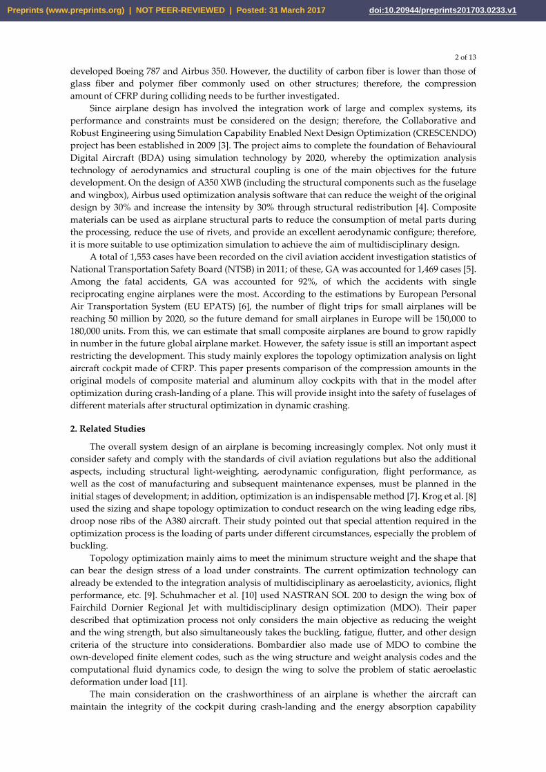
In this study, the 3D model for the cockpit and fuselage structure of Zenith CH 701 was built using the Pro/ENGINEER software (Figure 1). Then, the parameter setting and the structural topology optimization of aluminum alloy and CFRP were conducted using the Abaqus/Optimization. The output results were imported into Abaqus/Explicit to establish a dynamic crash-landing simulation for comparing the differences in the overall safety and the compression amount of fuselage at each direction between the original model and the optimized model for the light aircraft structure of the two different materials under dynamic impact. The structural optimization simulation for the impact resistance capability or the crashworthiness design of light aircraft studied in this paper is mainly based on the crashing parameters 1.3Vso and 30° nose-down angle, laid out by AGATE and the ASTM F2245 [20]; we also take the minimum safety standard as the term drafted by the MIL-STD -1290A, whereby the allowable deformation amount of cockpit in the horizontal direction, vertical direction, or lateral direction shall not be more than 15%. The optimization simulation in this study takes minimizing the strain energy as the objective function, that is, the minimum strain satisfied under the above-mentioned crashing condition. The structure optimization of this simulation takes the minimum volume that fulfils the cockpit rationalization design as the constraint. The material coefficients of aluminum alloy and CFRP in this paper are shown in Table 1, where the CFRP is a lamina of 0o fiber.
Preprints (www.preprints.org) | NOT PEER-REVIEWED | Posted: 31 March 2017 doi:10.20944/preprints201703.0233.v1
4 of 13
Figure 1. 3D model of the CH 701 fuselage.
Table 1. Properties of aluminum alloy and CFRP.
Al Alloy
6061-T6 CFRP
T300/LTM45-EL Density (g/cm3) 2.7 1.6 Young's Modulus (GPa) 68.9 E11 127
E22 9.1 E33 9.1
Shear Modulus (GPa) 26 G12 5.6 G13 5.6 G23 4
Poisson's Ratio 0.33 ν12 0.31 ν13 0.31 ν23 0.45
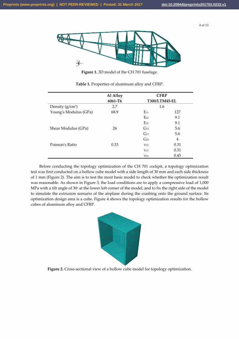
Before conducting the topology optimization of the CH 701 cockpit, a topology optimization test was first conducted on a hollow cube model with a side length of 30 mm and each side thickness of 1 mm (Figure 2). The aim is to test the most basic model to check whether the optimization result was reasonable. As shown in Figure 3, the load conditions are to apply a compressive load of 1,000 MPa with a tilt angle of 30o at the lower left corner of the model, and to fix the right side of the model to simulate the extrusion scenario of the airplane during the crashing onto the ground surface. Its optimization design area is a cube. Figure 4 shows the topology optimization results for the hollow cubes of aluminum alloy and CFRP.
Figure 2. Cross-sectional view of a hollow cube model for topology optimization.
Preprints (www.preprints.org) | NOT PEER-REVIEWED | Posted: 31 March 2017 doi:10.20944/preprints201703.0233.v1

5 of 13
Figure 3. Hollow cube and load conditions.
(a) (b) Figure 4. Topology optimization results for hollow cubes made of aluminum alloy and composite materials: (a) 6061-T6 aluminum alloy; (b) T300/LTM45 CFRP.
As shown in Figure 4, one inclined beam emerges along the 30o load direction in both the aluminum alloy and the CFRP structures; however, another strut forming about 90o with the inclined beam emerges in CFRP. The purpose of this study is to investigate whether the presence of this strut is related to the shear modulus (G); thus, G12, G13, and G23 for the CFRP parameters are changed to explore the influence of G value on the optimized structure. We take different G values, from 10 MPa, 102 MPa, 103 MPa, and 104 MPa, to respectively conduct the optimization simulations repeatedly. The results are shown in Figures 5–7. Figure 5 shows the results of the optimization structure at fixed G13 and G23, but varying G12. As revealed from the diagrams, when G12 increases, the columnar structure of inclined beam becomes more obvious; however, it was found that when G12 is greater than 103 MPa, there is no obvious change in the structure. Figure 6 shows the results of optimization structure at fixed G12 and G23 constant but varying G13. As indicated in the diagrams, while varying G13, although the side panels of the cockpit have slight changes, the main structural change is the different layout on the floor. Figure 7 shows the results of optimization structure at fixed G12 and G13 but varying G23. As indicated in the diagrams, when G23 varies, the main changes generated are on the side panels; when G23 is 104 MPa, even the phenomenon of structural separation is generated. Therefore, as revealed from the results of Figures 5–7, G12 is the main factor affecting the inclined strut.
Preprints (www.preprints.org) | NOT PEER-REVIEWED | Posted: 31 March 2017 doi:10.20944/preprints201703.0233.v1

6 of 13
(a) (b)
(c) (d) Figure 5. Influence of varying G12 values on the optimized structure shape of the CFRP cockpit: (a) G12 = 10 MPa; (b) G12 = 102 MPa; (c) G12 = 103 MPa; (d) G12 = 104 MPa.
(a) (b)
(c) (d) Figure 6. Influence of varying G13 values on the optimized structure shape of the CFRP cockpit: (a) G13 = 10 MPa; (b) G13 = 102 MPa; (c) G13 = 103 MPa; (d) G13 = 104 MPa.
(a) (b)
(c) (d) Figure 7. Influence of varying G23 values on the optimized structure shape of the CFRP cockpit: (a) G23 = 10 MPa; (b) G23 = 102 MPa; (c) G23 = 103 MPa; (d) G23 = 104 MPa.
Preprints (www.preprints.org) | NOT PEER-REVIEWED | Posted: 31 March 2017 doi:10.20944/preprints201703.0233.v1
7 of 13
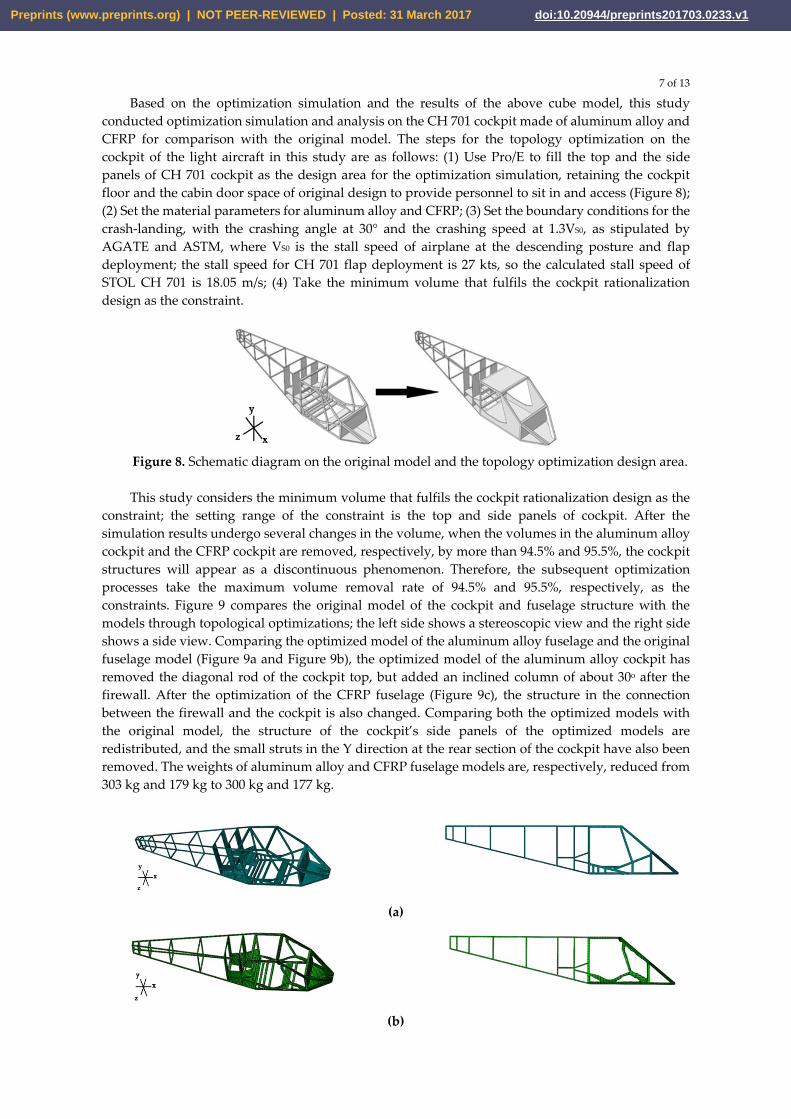
Based on the optimization simulation and the results of the above cube model, this study conducted optimization simulation and analysis on the CH 701 cockpit made of aluminum alloy and CFRP for comparison with the original model. The steps for the topology optimization on the cockpit of the light aircraft in this study are as follows: (1) Use Pro/E to fill the top and the side panels of CH 701 cockpit as the design area for the optimization simulation, retaining the cockpit floor and the cabin door space of original design to provide personnel to sit in and access (Figure 8); (2) Set the material parameters for aluminum alloy and CFRP; (3) Set the boundary conditions for the crash-landing, with the crashing angle at 30° and the crashing speed at 1.3VS0, as stipulated by AGATE and ASTM, where VS0 is the stall speed of airplane at the descending posture and flap deployment; the stall speed for CH 701 flap deployment is 27 kts, so the calculated stall speed of STOL CH 701 is 18.05 m/s; (4) Take the minimum volume that fulfils the cockpit rationalization design as the constraint.
Figure 8. Schematic diagram on the original model and the topology optimization design area.
This study considers the minimum volume that fulfils the cockpit rationalization design as the
constraint; the setting range of the constraint is the top and side panels of cockpit. After the simulation results undergo several changes in the volume, when the volumes in the aluminum alloy cockpit and the CFRP cockpit are removed, respectively, by more than 94.5% and 95.5%, the cockpit structures will appear as a discontinuous phenomenon. Therefore, the subsequent optimization processes take the maximum volume removal rate of 94.5% and 95.5%, respectively, as the constraints. Figure 9 compares the original model of the cockpit and fuselage structure with the models through topological optimizations; the left side shows a stereoscopic view and the right side shows a side view. Comparing the optimized model of the aluminum alloy fuselage and the original fuselage model (Figure 9a and Figure 9b), the optimized model of the aluminum alloy cockpit has removed the diagonal rod of the cockpit top, but added an inclined column of about 30o after the firewall. After the optimization of the CFRP fuselage (Figure 9c), the structure in the connection between the firewall and the cockpit is also changed. Comparing both the optimized models with the original model, the structure of the cockpit’s side panels of the optimized models are redistributed, and the small struts in the Y direction at the rear section of the cockpit have also been removed. The weights of aluminum alloy and CFRP fuselage models are, respectively, reduced from 303 kg and 179 kg to 300 kg and 177 kg.
(a)
(b)
Preprints (www.preprints.org) | NOT PEER-REVIEWED | Posted: 31 March 2017 doi:10.20944/preprints201703.0233.v1

8 of 13
(c) Figure 9. (a) Original model; (b) Topology optimization model of aluminum alloy; (c) Topology optimization model of CFRP.
4. Results and Discussions
This study mainly explores the safety difference of topography optimization models for light aircraft fuselages made of CFRP and aluminum alloy compared with the original design model when the aircraft crash-landing onto the ground surface. This study conducted the crash-landing simulations by taking the impact angle (30o) and impact speed (1.3 VS0) laid out by AGATE and ASTM as boundary conditions, and considering the safety criteria as specified by MIL-STD-1290A, whereby the allowable compression amount in each direction of the cockpit cannot be more than 15%. The accuracy of the simulation parameter settings and the validation of the results are obtained by judging from the change in the output energy from Abaqus/Explicit during crashing onto the ground surface. The changes should follow the trend described as follows: (1) Kinetic energy (EKE) decreases, internal energy (EI) increases, and the total energy (ETotal) must be conserved; (2) Artificial strain energy (EA) must be less than 2% of the internal energy to ensure the correctness of the model meshing. Figure 10 shows the energy change in the optimized model of the CFRP fuselage at an impact angle of 30o and an impact speed of 18.05 m/s. As indicated by this graph, during the process, the kinetic energy decreases, the potential energy increases, and total energy remains constant; in addition, EA is less than 2% of EI. From this, we can know the reasonableness of the simulation results for the original model and the optimized model. The original model and optimized model of the aluminum alloy fuselage as well as the CFRP fuselage original model all obtained similar results.
Table 2 shows the variation in the internal energy (EI) absorption and specific energy absorption (SEA) for the original models and the optimized models of the aluminum alloy and CFRP fuselage at the time of crashing (impact angle 30o and impact speed of 18.05 m/s); here SEA is defined as the energy absorption capability per unit weight (Joule/kg). As revealed from Table 2, comparing the energy absorption capability of the models of aluminum alloy fuselage and CFRP fuselage after optimization with the original models of both, it can be increased by 39.57% and 14.65%, respectively. When comparing the SEA values of original models and optimized models for fuselages of the two materials at the time of crash-landing, the optimized model for the aluminum alloy fuselage is still the best among the four. Here, this SEA value is higher than that of the optimized model for CFRP fuselage by 31%; moreover, it increased by 41% and 51%, respectively, compared to that of the original model of the aluminum alloy fuselage or that of the original model of composite material fuselage. In comparison of the energy absorptions of the four models, the aluminum alloy fuselage still has higher energy absorptions than the CFRP fuselage. This is mainly because the high ductility of aluminum alloy material has better performance on the energy absorption capability.
Preprints (www.preprints.org) | NOT PEER-REVIEWED | Posted: 31 March 2017 doi:10.20944/preprints201703.0233.v1

9 of 13
Figure 10. Energy changes in optimized model of the CFRP fuselage during the crashing process.
Table 2. Internal energy absorption for original models and optimized models of aluminum alloy and composite fuselages.
EI (J) SEA (J/kg) Original model of aluminum alloy fuselage 3,608.63 11.91 Optimized model of aluminum alloy fuselage
5,036.64 16.79
Original model of CFRP fuselage 1,985.90 11.09 Optimized model of CFRP fuselage 2,276.87 12.86
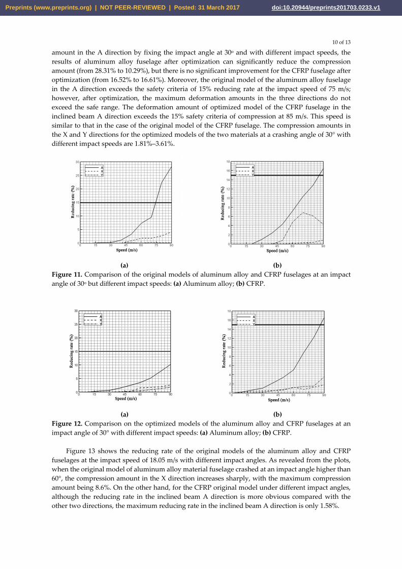
Figure 11 shows the compression results of original models for fuselages of aluminum alloy and
CFRP at a fixed impact angle of 30° but varying impact speeds. As revealed from the plots, the inclined beam A is the structure having the most obvious change in the compression amount among the three directions. The maximum reducing rate in the original model for fuselage of aluminum alloy and the original model for fuselage of CFRP in the inclined beam A direction are 28.31% and 16.52%, respectively. Therefore, the reducing rate of original model for CFRP fuselage in this direction has been reduced by 11.79%. The reducing rate in the inclined beam A direction is an important factor during the crash-landing of the airplane because the extrusion in this direction may cause the cockpit structure to crush the passenger's head and cause serious injury. In the original models of the aluminum alloy and CFRP fuselages with fixed impact angle of 30o, the reducing rate in the inclined beam A direction force exceed the safety criteria of 15% at the impact speed of 75 m/s and 85 m/s, respectively. The deformation of the original model for the aluminum alloy fuselage in the X direction only slightly increases when the impact speed increases. The maximum value of deformation was 4.2% occurring at 90 m/s, but the maximum reducing rate in the original model for CFRP fuselage is only 0.9% at 90 m/s. The reducing rate in the Y direction for the original model of the aluminum alloy fuselage does not show significant changes, but the maximum reducing rate for the original model of the CFRP fuselage is 6.85% at an impact speed of 70 m/s.
Figure 12 shows the reducing rate for the optimized models of the aluminum alloy and CFRP fuselages at an impact angle of 30o with different impact speeds. As revealed from Figures 11 and 12, the inclined beam A is the structure having the most obvious changes in the compression amount among the three directions at a fixed impact angle of 30o and different impact speeds, regardless of whether the model is original or optimized. The maximum deformation amounts of the optimized model of the aluminum alloy fuselage and the optimized model of the CFRP fuselage in the inclined beam A direction are 10.29% and 16.61%, respectively. Comparing the maximum deformation
Preprints (www.preprints.org) | NOT PEER-REVIEWED | Posted: 31 March 2017 doi:10.20944/preprints201703.0233.v1
10 of 13
amount in the A direction by fixing the impact angle at 30o and with different impact speeds, the results of aluminum alloy fuselage after optimization can significantly reduce the compression amount (from 28.31% to 10.29%), but there is no significant improvement for the CFRP fuselage after optimization (from 16.52% to 16.61%). Moreover, the original model of the aluminum alloy fuselage in the A direction exceeds the safety criteria of 15% reducing rate at the impact speed of 75 m/s; however, after optimization, the maximum deformation amounts in the three directions do not exceed the safe range. The deformation amount of optimized model of the CFRP fuselage in the inclined beam A direction exceeds the 15% safety criteria of compression at 85 m/s. This speed is similar to that in the case of the original model of the CFRP fuselage. The compression amounts in the X and Y directions for the optimized models of the two materials at a crashing angle of 30° with different impact speeds are 1.81%–3.61%.
(a) (b) Figure 11. Comparison of the original models of aluminum alloy and CFRP fuselages at an impact angle of 30o but different impact speeds: (a) Aluminum alloy; (b) CFRP.
(a) (b) Figure 12. Comparison on the optimized models of the aluminum alloy and CFRP fuselages at an impact angle of 30° with different impact speeds: (a) Aluminum alloy; (b) CFRP.
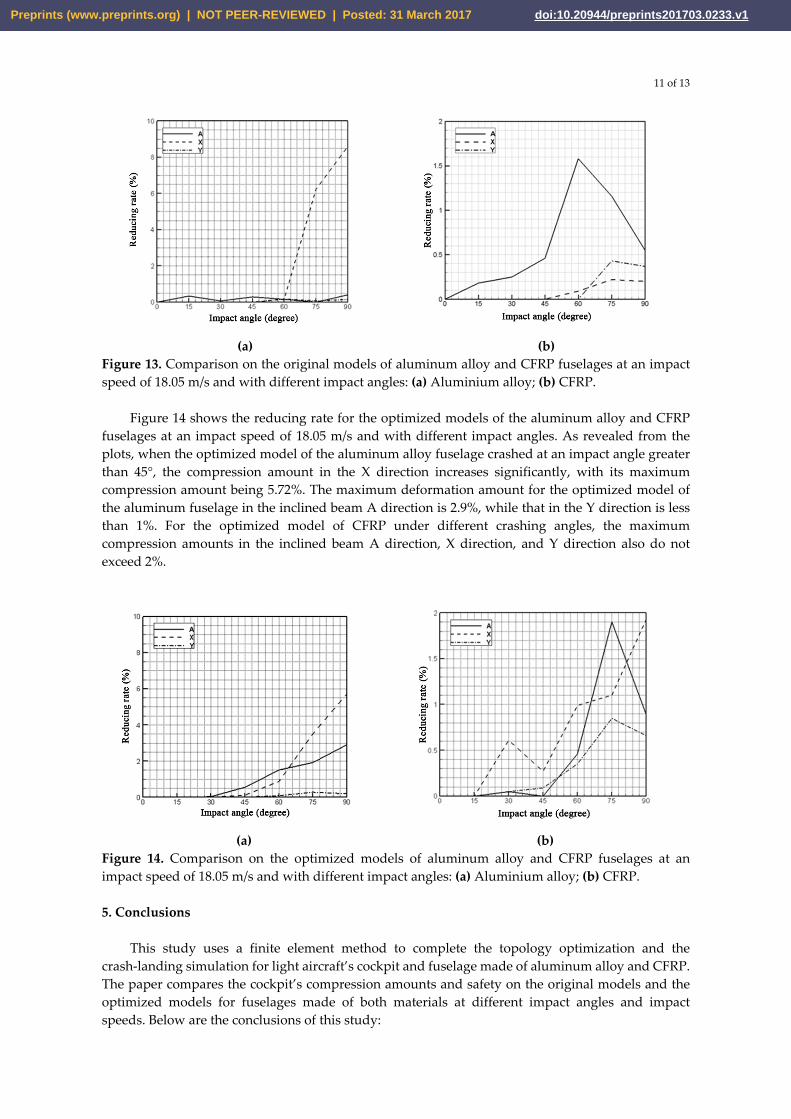
Figure 13 shows the reducing rate of the original models of the aluminum alloy and CFRP
fuselages at the impact speed of 18.05 m/s with different impact angles. As revealed from the plots, when the original model of aluminum alloy material fuselage crashed at an impact angle higher than 60°, the compression amount in the X direction increases sharply, with the maximum compression amount being 8.6%. On the other hand, for the CFRP original model under different impact angles, although the reducing rate in the inclined beam A direction is more obvious compared with the other two directions, the maximum reducing rate in the inclined beam A direction is only 1.58%.
Preprints (www.preprints.org) | NOT PEER-REVIEWED | Posted: 31 March 2017 doi:10.20944/preprints201703.0233.v1
11 of 13
(a) (b) Figure 13. Comparison on the original models of aluminum alloy and CFRP fuselages at an impact speed of 18.05 m/s and with different impact angles: (a) Aluminium alloy; (b) CFRP.
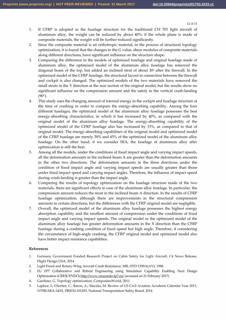
Figure 14 shows the reducing rate for the optimized models of the aluminum alloy and CFRP
fuselages at an impact speed of 18.05 m/s and with different impact angles. As revealed from the plots, when the optimized model of the aluminum alloy fuselage crashed at an impact angle greater than 45°, the compression amount in the X direction increases significantly, with its maximum compression amount being 5.72%. The maximum deformation amount for the optimized model of the aluminum fuselage in the inclined beam A direction is 2.9%, while that in the Y direction is less than 1%. For the optimized model of CFRP under different crashing angles, the maximum compression amounts in the inclined beam A direction, X direction, and Y direction also do not exceed 2%.
(a) (b) Figure 14. Comparison on the optimized models of aluminum alloy and CFRP fuselages at an impact speed of 18.05 m/s and with different impact angles: (a) Aluminium alloy; (b) CFRP.
5. Conclusions
This study uses a finite element method to complete the topology optimization and the
crash-landing simulation for light aircraft’s cockpit and fuselage made of aluminum alloy and CFRP. The paper compares the cockpit’s compression amounts and safety on the original models and the optimized models for fuselages made of both materials at different impact angles and impact speeds. Below are the conclusions of this study:
Preprints (www.preprints.org) | NOT PEER-REVIEWED | Posted: 31 March 2017 doi:10.20944/preprints201703.0233.v1
12 of 13
1. If CFRP is adopted as the fuselage structure for the traditional CH 701 light aircraft of aluminum alloy, the weight can be reduced by about 40%; if the whole plane is made of composite materials, the weight will be further reduced significantly.
2. Since the composite material is an orthotropic material, in the process of structural topology optimization, it is found that the changes in the G value, shear modulus of composite materials along different directions, have significant influence on the structure shape.
3. Comparing the difference in the models of optimized fuselage and original fuselage made of aluminum alloy, the optimized model of the aluminum alloy fuselage has removed the diagonal beam of the top, but added an inclined strut of about 30o after the firewall. In the optimized model of the CFRP fuselage, the structural layout in connection between the firewall and cockpit is also changed. The optimized models of the two materials have removed the small struts in the Y direction at the rear section of the original model, but the results show no significant influence on the compression amount and the safety in the vertical crash-landing (90°).
4. This study uses the changing amount of internal energy in the cockpit and fuselage structure at the time of crashing in order to compare the energy-absorbing capability. Among the four different fuselages, the optimized model of the aluminum alloy fuselage possesses the best energy-absorbing characteristics, in which it has increased by 40%, as compared with the original model of the aluminum alloy fuselage. The energy-absorbing capability of the optimized model of the CFRP fuselage also has increased by 15%, as compared to that of original model. The energy-absorbing capabilities of the original model and optimized model of the CFRP fuselage are merely 39% and 45% of the optimized model of the aluminum alloy fuselage. On the other hand, if we consider SEA, the fuselage of aluminum alloy after optimization is still the best.
5. Among all the models, under the conditions of fixed impact angle and varying impact speeds, all the deformation amounts in the inclined beam A are greater than the deformation amounts in the other two directions. The deformation amounts in the three directions under the condition of fixed impact angle and varying impact speeds are usually greater than those under fixed impact speed and varying impact angles. Therefore, the influence of impact speed during crash-landing is greater than the impact angle.
6. Comparing the results of topology optimization on the fuselage structure made of the two materials, there are significant effects in case of the aluminum alloy fuselage. In particular, the compression amount reduces the most in the inclined beam A direction. In the results of CFRP fuselage optimization, although there are improvements in the structural compression amounts in certain directions, but the differences with the CFRP original model are negligible.
7. Overall, the optimized model of the aluminum alloy fuselage possesses the highest energy absorption capability and the smallest amount of compression under the conditions of fixed impact angle and varying impact speeds. The original model or the optimized model of the aluminum alloy fuselage has greater deformation amounts in the X direction than the CFRP fuselage during a crashing condition of fixed speed but high angle. Therefore, if considering the circumstance of high-angle crashing, the CFRP original model and optimized model also have better impact resistance capabilities.
References
1. Germany Government Funded Research Project on Cabin Safety for Light Aircraft, C4 News Release, Flight Design USA, 2014.
2. Light Fixed and Rotary-Wing Aircraft Crash Resistance, MIL-STD-1290A(AV), 1988. 3. EU FP7 Collaborative and Robust Engineering using Simulation Capability Enabling Next Design
Optimisation (CRESCENDO) http://www.crescendo-fp7.eu/ (accessed on 21 February 2017) 4. Gardiner, G. Topology optimization, CompositesWorld, 2011. 5. Laplace, I.; Chertier, C.; Baron, A.; Maczka, M. Review of US Civil Aviation Accidents Calendar Year 2011,
NTSB/ARA-14/01, PB2014-101453, National Transportation Safety Board, 2014.
Preprints (www.preprints.org) | NOT PEER-REVIEWED | Posted: 31 March 2017 doi:10.20944/preprints201703.0233.v1

13 of 13
6. D2.1 Potential Transfer of Passenger Demand to Personal Aviation by 2020, ASA6-CT-2006-044549, European Personal Air Transportation System, 2008.
7. Roy, R.; Hinduja, S.; Teti, R. Recent Advances in Engineering Design Optimisation: Challenges and Future Trends, CIRP Annals - Manufacturing Technology, 2008, 57, 697-715.
8. Krog, L.; Tucker, A.; Kemp, M.; Boyd, R., Topology Optimization of Aircraft Wing Box Ribs, 10th AIAA/ISSMO Multidisciplinary Analysis and Optimization Conference, AIAA 2004-4481, Albany, New York, 2004.
9. Hall, A.; Mayer, T.; Wuggetzer, I.; Childs, P.R.N. Future Aircraft Cabins and Design Thinking: Optimisation vs. Win-Win Scenarios, Propulsion and Power Research, 2008, 2, 85-95.
10. Schuhmacher, G.; Murra, I.; Wang, L.; Laxander, A.; O'Leary, O.; Herold, M. Multidisciplinary Design Optimization of a Regional Aircraft Wing Box, AIAA 2002-5406, 9th AIAA/ISSMO Symposium on Multidisciplinary Analysis and Optimization, Atlanta, Georgia, 2002, doi: 10.2514/6.2002-5406
11. Piperni, P.; Adbo, M.; Kafyeke, F. The Application of Muliti-Disciplinary Optimization Technologies to the Design of a Business Jet, 10th AIAA/ISSMO Multidisciplinary Analysis and Optimization Conference, AIAA 2004-4370, Albany, New York, 2004.
12. Hurley, T.R.; Vandenburg, J.M. Small Airplane Crashworthiness Design Guide, AGATE-WP3.4-034043-036, April 12, 2002.
13. Hooper, S.; Henderson, M.; Seneviratne, W. Design and Construction of a Crashworthy Composite Airframe, AGATE-WP3.4-034026-089, Rev. A, March 1, 2002.
14. Feraboli, P. Development of a Corrugated Test Specimen for Composite Materials Energy Absorption, J. Compos. Mater. , 2008, 42, 229-256, doi: 10.1177/0021998307086202
15. Feindler, N.; Döll, J.; Drechsler, K. Test Method to Analyse the Energy Absorption of Composite Material using Flat Coupon Testing, 5th International Conference on Composites Testing and Model Simulation, EPFL, Lausanne, 2011.
16. Zhou, M.; Fleury, R.; Patten, S.; Stannard, N.; Mylett, D.; Gardner, S. Topology Optimization – Practical Aspects for Industrial Applications, 9th World Congress on Structural and Multidisciplinary Optimization, Shizuoka, Japan, June 13-17, 2011.
17. Liu, D.; Lohse-Buschl, H.; Toropov, V.; Hühne, C.; Armani, U. Detailed Design of a Lattice Composite Fuselage Structure by a Mixed Optimization Method, Engineering Optimization, 2016, 48, 1707-1720.
18. Giordano, V.; Coiro, D.P.; Nicolosi, F.; Leo, L.D. Design and Aerodynamic Optimization of a New Reconnaissance Very Light Aircraft Through Wind-Tunnel Tests, Aerodynamic Design and Optimisation of Flight Vehicles in a Concurrent Multi-Disciplinary Environment, RTO AVT Symposium, Ottawa, Canada, October 18-21, 1999, 34.1-34.8.
19. Ahamed S.N.; Kumar, J.V.; Sravani, P. Weight Optimization of Empennage of Light Weight Aircraft, International Journal of Scientific & Technology Research, vol. 3, issue 4, April 2014.
20. ASTM F2245-16a, Standard Specification for Design and Performance of a Light Sport Airplane, ASTM International, West Conshohocken, PA, 2016.
© 2017 by the authors. Licensee Preprints, Basel, Switzerland. This article is an open access article distributed under the terms and conditions of the Creative Commons by Attribution (CC-BY) license (http://creativecommons.org/licenses/by/4.0/).
Preprints (www.preprints.org) | NOT PEER-REVIEWED | Posted: 31 March 2017 doi:10.20944/preprints201703.0233.v1