ARTICLE BEGINNING TECHNICAL INSTRUCTIONS
171
2000 THROUGH 2003 MODEL YEAR TUNDRA FRAME REPLACEMENT SERVICE CAMPAIGN BULLETIN Reference Number(s): LSC A0F, Date of Issue: May 12, 2010 TOYOTA: 2000 - 2003 Tundra SECTION: Limited Service Campaign Superceded Bulletin(s): LSC A0F, Date of Issue: May 12, 2010 Related Ref Number(s): (LSC) A0F ARTICLE BEGINNING TECHNICAL INSTRUCTIONS NOTE: TECHNICAL INSTRUCTION REVISION NOTICE: May 12, 2010: • The Operation Flow Chart was updated. ◦ Previous versions of this Technical Instruction should be discarded. I. OPERATION FLOWCHART Page 1 of 171 2000 THROUGH 2003 MODEL YEAR TUNDRA FRAME REPLACEMENT -2002 To... 11/11/2011 http://www.ondemand5.com/mric/common/asp/printart.aspx
Transcript of ARTICLE BEGINNING TECHNICAL INSTRUCTIONS

2000 THROUGH 2003 MODEL YEAR TUNDRA FRAME REPLACEMENT
SERVICE CAMPAIGN BULLETIN
Reference Number(s): LSC A0F, Date of Issue: May 12, 2010TOYOTA: 2000 - 2003 TundraSECTION:Limited Service CampaignSuperceded Bulletin(s): LSC A0F, Date of Issue: May 12, 2010Related Ref Number(s): (LSC) A0F
ARTICLE BEGINNING
TECHNICAL INSTRUCTIONS
NOTE: TECHNICAL INSTRUCTION REVISION NOTICE:
May 12, 2010:•
The Operation Flow Chart was updated.◦
Previous versions of this Technical Instruction should be discarded.
I. OPERATION FLOWCHART
Page 1 of 1712000 THROUGH 2003 MODEL YEAR TUNDRA FRAME REPLACEMENT -2002 To...
11/11/2011http://www.ondemand5.com/mric/common/asp/printart.aspx

II. PREPARATION
A. TOOLS & EQUIPMENT
A/C service equipment•
Alignment rack•
Brake bleeder•
Engine Hanger•
5VZ-FE Engine for vehicles produced on or before August 2002•
Page 2 of 1712000 THROUGH 2003 MODEL YEAR TUNDRA FRAME REPLACEMENT -2002 To...
11/11/2011http://www.ondemand5.com/mric/common/asp/printart.aspx

12282-62050 - Engine hanger no. 2 (Qty: 1) ◦
90080-11443 - Bolt (Qty: 1)◦
5VZ-FE Engine for vehicles produced after August 2002•
12282-62070 - Engine hanger no. 2 (Qty: 1) ◦
90080-11443 - Bolt (Qty: 1)◦
Engine hoist (Qty: 2) or Hydraulic mini crane (Qty 2)•
Engine sling•
Protective eyewear•
Protective gloves•
Ratcheting tie down strap (2 in X 27 ft, minimum work load capacity: 3,000 lbs)•
Special Service Tools (SST)•
07110-58060 - Air conditioner service tool set or Commercially available airconditioning manifold gauge set
•
09325-40010 - Transmission oil plug•
09610-20012 - Pit man arm puller•
09617-24011 - A component of SST 09612-24014, Steering housing overhaul ToolKit or commercially available 22 mm Crowfoot wrench
•
09628-62011 - Ball joint puller•
09709-29018 - LSPV gauge set•
09922-10010-01 - Variable open wrench•
Standard hand tools•
Techstream•
Torque wrench•
Torx® T55H tamper resistant socket•
B. SUPPLIES
ATF D-II or DEXRON® III (DEXRON® II) - As needed•
Hypoid gear oil API GL-5 SAE 75W-90 - 1.3 Quarts•
R134a refrigerant - As needed•
Toyota DOT 3 brake fluid - 3 pints•
Toyota long life coolant - 2 gallons•
Vinyl tape•
C. PARTS
To assist dealers in determining the correct part number(s) to order, a website has been set up tolook up part numbers by VIN. Please go to http://lsc-aof.imagespm.info/ (also linked throughTIS), enter the VIN, and the correct part numbers to order will be displayed. The website is forpart(s) application reference only and will not order the part, nor will it confirm campaigncompletion status.
The parts will need to be ordered through the Dealer Daily Parts system.•
ETAs for the parts will be available via the normal system.•
Page 3 of 1712000 THROUGH 2003 MODEL YEAR TUNDRA FRAME REPLACEMENT -2002 To...
11/11/2011http://www.ondemand5.com/mric/common/asp/printart.aspx

Frame ETAs will be made available on the Dealer Daily website, in the MAC reference area.•
An illustration of the parts replaced and their location(s) have been provided. Please reference the"Illustration Name" and "Page" columns in the parts tables below.
Individual Parts:
"INDIVIDUAL PARTS" PARTS INFORMATION
PartNumber
Part Description QuantityIllustration
NamePage
04000-2310C
Frame, Sub-Assy 1Frame & Misc
Parts13
04000-2320C
Frame, Sub-Assy 1Frame & Misc
Parts13
04000-2330C
Frame, Sub-Assy 1Frame & Misc
Parts13
04000-2340C
Frame, Sub-Assy 1Frame & Misc
Parts13
04000-2350C
Frame, Sub-Assy 1Frame & Misc
Parts13
04000-2360C
Frame, Sub-Assy 1Frame & Misc
Parts13
04000-2370C
Frame, Sub-Assy 1Frame & Misc
Parts13
04000-2380C
Frame, Sub-Assy 1Frame & Misc
Parts13
04000-2390C
Frame, Sub-Assy 1Frame & Misc
Parts13
04000-2410C
Frame, Sub-Assy 1Frame & Misc
Parts13
04000-2420C
Frame, Sub-Assy 1Frame & Misc
Parts13
04000-2430C
Frame, Sub-Assy 1Frame & Misc
Parts13
04000-2440C
Frame, Sub-Assy 1Frame & Misc
Parts13
04000-2450C
Frame, Sub-Assy 1Frame & Misc
Parts13
04000-2460C
Frame, Sub-Assy 1Frame & Misc
Parts13
04000-2470C
Frame, Sub-Assy 1Frame & Misc
Parts13
04000-2480C
Frame, Sub-Assy 1Frame & Misc
Parts13
04000-2490C
Frame, Sub-Assy 1Frame & Misc
Parts13
Page 4 of 1712000 THROUGH 2003 MODEL YEAR TUNDRA FRAME REPLACEMENT -2002 To...
11/11/2011http://www.ondemand5.com/mric/common/asp/printart.aspx

PartNumber
Part Description QuantityIllustration
NamePage
04000-2510C
Frame, Sub-Assy 1Frame & Misc
Parts13
04000-2520C
Frame, Sub-Assy 1Frame & Misc
Parts13
04000-2530C
Frame, Sub-Assy 1Frame & Misc
Parts13
04000-2540C
Frame, Sub-Assy 1Frame & Misc
Parts13
04000-2550C
Frame, Sub-Assy 1Frame & Misc
Parts13
04000-2560C
Frame, Sub-Assy 1Frame & Misc
Parts13
04000-2570C
Frame, Sub-Assy 1Frame & Misc
Parts13
04000-2580C
Frame, Sub-Assy 1Frame & Misc
Parts13
04000-2590C
Frame, Sub-Assy 1Frame & Misc
Parts13
04000-2610C
Frame, Sub-Assy 1Frame & Misc
Parts13
04000-2620C
Frame, Sub-Assy 1Frame & Misc
Parts13
04000-2630C
Frame, Sub-Assy 1Frame & Misc
Parts13
04000-2660C
Frame, Sub-Assy 1Frame & Misc
Parts13
04000-2670C
Frame, Sub-Assy 1Frame & Misc
Parts13
04000-2680C
Frame, Sub-Assy 1Frame & Misc
Parts13
04483-0C030
Shackle Kit, Rear Spring 2 Rear Suspension 13
12157-10010
Gasket, Front Differential Filler Plug 1 Front Differential 20
16492-21050
Packing (For Radiator Drain Cock) 1 Radiator 25
18495-38020
Retainer, Exhaust Pipe 2 Exhaust System 23
18495-76010
Retainer, Exhaust Pipe 1 Exhaust System 23
23232-41081
Gasket (For Fuel Pump Hose) 1 Fuel System 22
43425-04020
Ring, Shaft Snap (For Front Drive InnerShaft Outer)
2 Front Driveshaft 20
Page 5 of 1712000 THROUGH 2003 MODEL YEAR TUNDRA FRAME REPLACEMENT -2002 To...
11/11/2011http://www.ondemand5.com/mric/common/asp/printart.aspx

PartNumber
Part Description QuantityIllustration
NamePage
47322-0C011
Tube, Rear Brake, No.2 1 Brake Tubes 15
47322-0C012
Tube, Rear Brake, No.2 1 Brake Tubes 15
47323-0C011
Tube, Rear Brake, No.3 1 Brake Tubes15-16
47323-0C012
Tube, Rear Brake, No.3 1 Brake Tubes15-16
47361-0C011
Tube, Rear Brake, No.10 1 Brake Tubes15-16
47361-0C012
Tube, Rear Brake, No.10 1 Brake Tubes15-16
77601-34030
Fuel Tank Strap, No. 1 1 Fuel Tank 24
77601-34040
Fuel Tank Strap, No. 1 1 Fuel Tank 24
77603-34060
Fuel Tank Strap, No. 2 1 Fuel Tank 24
77603-34070
Fuel Tank Strap, No. 2 1 Fuel Tank 24
90080-43033
Gasket, Exhaust Pipe 1 Exhaust System 23
90080-43034
Gasket, Exhaust Pipe 2 Exhaust System 23
90430-12026
Gasket (For Pulsation Damper Hose) 2 Fuel System 22
90430-24003
Gasket, Front Differential Drain Plug 1 Front Differential 20
90917-06057
Gasket, Exhaust Pipe 1 Exhaust System 23
90917-06083
Gasket, Exhaust Pipe 2 Exhaust System 23
95381-04045
Cotter Pin 2 Front Driveshaft 20
96711-19007
Packing (For Radiator Drain Cock) 1 Radiator 25
Parts Kits:
PARTS KIT NO. 1
Part Number Part Description Quantity
04009-49134 Parts Kit No. 1 - Common Replacement Kit A-1 1
The kit listed above includes the following parts:
Page 6 of 1712000 THROUGH 2003 MODEL YEAR TUNDRA FRAME REPLACEMENT -2002 To...
11/11/2011http://www.ondemand5.com/mric/common/asp/printart.aspx

PARTS KIT NO. 2 PARTS INFORMATION
PartNumber
Part Description Quantity Illustration Name Page
47353-35110
Bracket, Flexible Hose, No. 3 1 Brake Tubes15-16
47354-35100
Bracket, Flexible Hose, No. 4 1 Brake Tubes15-16
47931-34020
Bracket, Load sensing Valve 1 LSPV 19
47937-60010
Plate, Load Sensing Valve Set 1 LSPV 19
48409-34020
Cam Sub-Assy, Front Suspension ToeAdjust
2 Front Suspension 14
48409-34030
Cam Sub-Assy, Front Suspension ToeAdjust, No. 2
2 Front Suspension 14
48452-35020
Plate, Front Suspension Toe Adjust, No.2
4 Front Suspension 14
48824-34020
Bracket, Front Stabilizer No. 1 RH 1 Front Suspension 14
48829-34010
Bracket, Front Stabilizer No. 1 LH 1 Front Suspension 14
77285-34030
Clamp, Fuel Tube, No. 1 4 Fuel Tubes 17
77285-34040
Clamp, Fuel Tube, No. 1 1 Fuel Tubes 17
77285-34050
Clamp, Fuel Tube, No. 1 1 Fuel Tubes 17
77285-34060
Clamp, Fuel Tube, No. 1 1 Fuel Tubes 17
77285-34070
Clamp, Fuel Tube, No. 1 2 Fuel Tubes 17
77285-34080
Clamp, Fuel Tube, No. 1 1 Fuel Tubes 17
77775-34010
Guide, Canister Outlet 1 Fuel Tubes 17
82666-35200
Holder, Connector 2 ABS 21
82711-1E320
Support, Wiring Harness 1Wire Harness
Clamps19
82711-1E360
Support, Wiring Harness 1Wire Harness
Clamps19
82711-21020
Support, Wiring Harness 1Wire Harness
Clamps19
82711-26380
Support, Wiring Harness 15Wire Harness
Clamps19
Page 7 of 1712000 THROUGH 2003 MODEL YEAR TUNDRA FRAME REPLACEMENT -2002 To...
11/11/2011http://www.ondemand5.com/mric/common/asp/printart.aspx

PartNumber
Part Description Quantity Illustration Name Page
82711-3A640
Support, Wiring Harness 1Wire Harness
Clamps19
82711-3F050
Support, Wiring Harness 3Wire Harness
Clamps19
89515-35030
Clamp 2 ABS 21
90099-14120
O-Ring 1 Air Conditioning 24
90099-14121
O-Ring 1 Air Conditioning 24
90119-12311
Bolt 4 Rear Bumper 25
90159-60440
Screw 4Frame & Misc
Parts13
90178-10024
Nut 4 Front Bumper 25
90179-06314
Nut 2 Front Bumper 25
90179-08054
Nut 1 AT Shift Cable 25
90179-08063
Nut 2 Front Bumper 25
90179-08256
Nut 2 Front Suspension 14
90179-10071
Nut 4 Engine Mounting 21
90179-14019
Nut 8 Rear Suspension 13
90179-14039
Nut 6 Rear Suspension 13
90201-09019
Washer 1 AT Shift Cable 25
90201-14025
Washer 6 Rear Suspension 13
90201-15012
Washer 8 Rear Suspension 13
90252-03015
Cotter Pin 2 Front Suspension 14
90467-13076
Clip 2 Bed Mounting 14
90468-08035
Clip 3 Brake Tubes15-16
90904-12066
Way, No. 2 (for front brake tube) 1 Brake Tubes15-16
Page 8 of 1712000 THROUGH 2003 MODEL YEAR TUNDRA FRAME REPLACEMENT -2002 To...
11/11/2011http://www.ondemand5.com/mric/common/asp/printart.aspx

PartNumber
Part Description Quantity Illustration Name Page
90904-12067
Way, No. 3 (for front brake tube) 1 Brake Tubes15-16
90904-12068
Way (for front brake tube) 1 Brake Tubes15-16
90949-01B59
Clamp 1 Brake Tubes15-16
90949-01B60
Clamp, Brake Tube, No. 6 5 Brake Tubes15-16
90949-01B61
Clamp, Brake Tube, No. 7 1 Brake Tubes15-16
91621-B0816
Bolt 5 Brake Tubes 16
95381-03225
Cotter Pin 2 Power Steering 21
PARTS KIT NO. 2
Part Number Part Description Quantity
04009-49234 Parts Kit No. 2 - Common Replacement Kit A-2 1
The kit listed above includes the following parts:
PARTS KIT NO. 2 PARTS INFORMATION
PartNumber
Part Description Quantity Illustration Name Page
47353-35110
Bracket, Flexible Hose, No. 3 1 Brake Tubes15-16
47354-35100
Bracket, Flexible Hose, No. 4 1 Brake Tubes15-16
47931-34020
Bracket, Load sensing Valve 1 LSPV 19
47937-60010
Plate, Load Sensing Valve Set 1 LSPV 19
48409-34020
Cam Sub-Assy, Front Suspension ToeAdjust
2 Front Suspension 14
48409-34030
Cam Sub-Assy, Front Suspension ToeAdjust, No. 2
2 Front Suspension 14
48452-35020
Plate, Front Suspension Toe Adjust, No.2
4 Front Suspension 14
48824-34030
Bracket, Front Stabilizer No. 1 RH 1 Front Suspension 14
48829-34020
Bracket, Front Stabilizer No. 1 LH 1 Front Suspension 14
77285-34031
Clamp, Fuel Tube, No. 1 4 Fuel Tubes 17
Page 9 of 1712000 THROUGH 2003 MODEL YEAR TUNDRA FRAME REPLACEMENT -2002 To...
11/11/2011http://www.ondemand5.com/mric/common/asp/printart.aspx

PartNumber
Part Description Quantity Illustration Name Page
77285-34041
Clamp, Fuel Tube, No. 1 1 Fuel Tubes 17
77285-34051
Clamp, Fuel Tube, No. 1 1 Fuel Tubes 17
77285-34060
Clamp, Fuel Tube, No. 1 1 Fuel Tubes 17
77285-34071
Clamp, Fuel Tube, No. 1 2 Fuel Tubes 17
77285-34080
Clamp, Fuel Tube, No. 1 1 Fuel Tubes 17
77775-34010
Guide, Canister Outlet 1 Fuel Tubes 17
82666-35200
Holder, Connector 2 ABS 21
82711-1E320
Support, Wiring Harness 1Wire Harness
Clamps19
82711-1E360
Support, Wiring Harness 1Wire Harness
Clamps19
82711-21020
Support, Wiring Harness 1Wire Harness
Clamps19
82711-26380
Support, Wiring Harness 15Wire Harness
Clamps19
82711-3A640
Support, Wiring Harness 1Wire Harness
Clamps19
82711-3F050
Support, Wiring Harness 3Wire Harness
Clamps19
89515-35030
Clamp 2 ABS 21
90099-14120
O-Ring 1 Air Conditioning 24
90099-14121
O-Ring 1 Air Conditioning 24
90119-12311
Bolt 4 Rear Bumper 25
90159-60440
Screw 4Frame & Misc
Parts13
90178-10024
Nut 4 Front Bumper 25
90179-06314
Nut 2 Front Bumper 25
90179-08054
Nut 1 AT Shift Cable 25
90179-08063
Nut 2 Front Bumper 25
Page 10 of 1712000 THROUGH 2003 MODEL YEAR TUNDRA FRAME REPLACEMENT -2002 ...
11/11/2011http://www.ondemand5.com/mric/common/asp/printart.aspx

PartNumber
Part Description Quantity Illustration Name Page
90179-10071
Nut 4 Engine Mounting 21
90179-14019
Nut 8 Rear Suspension 13
90179-14039
Nut 6 Rear Suspension 13
90182-10004
Nut 2 Front Suspension 14
90201-09019
Washer 1 AT Shift Cable 25
90201-14025
Washer 6 Rear Suspension 13
90201-15012
Washer 8 Rear Suspension 13
90252-03015
Cotter Pin 2 Front Suspension 14
90467-13076
Clip 2 Bed Mounting 14
90468-08035
Clip 3 Brake Tubes15-16
90904-12066
Way, No. 2 (for front brake tube) 1 Brake Tubes15-16
90904-12067
Way, No. 3 (for front brake tube) 1 Brake Tubes15-16
90904-12068
Way (for front brake tube) 1 Brake Tubes15-16
90949-01C06
Clamp, Brake Tube, No. 6 5 Brake Tubes15-16
90949-01C32
Clamp 1 Brake Tubes15-16
90949-01C33
Clamp, Brake Tube, No. 7 1 Brake Tubes15-16
91621-B0816
Bolt 5 Brake Tubes 16
95381-03225
Cotter Pin 2 Power Steering 21
PARTS KIT NO. 3
Part Number Part Description Quantity
04009-49334 Parts Kit No. 3 - Common Replacement Kit A-3 1
The kit listed above includes the following parts:
PARTS KIT NO. 3 PARTS INFORMATION
Page 11 of 1712000 THROUGH 2003 MODEL YEAR TUNDRA FRAME REPLACEMENT -2002 ...
11/11/2011http://www.ondemand5.com/mric/common/asp/printart.aspx

PartNumber
Part Description Quantity Illustration Name Page
47353-35110
Bracket, Flexible Hose, No. 3 1 Brake Tubes 15
47354-35100
Bracket, Flexible Hose, No. 4 1 Brake Tubes 15
47931-34020
Bracket, Load sensing Valve 1 LSPV 19
47937-60010
Plate, Load Sensing Valve Set 1 LSPV 19
48409-34020
Cam Sub-Assy, Front Suspension ToeAdjust
2 Front Suspension 14
48409-34030
Cam Sub-Assy, Front Suspension ToeAdjust, No. 2
2 Front Suspension 14
48452-35020
Plate, Front Suspension Toe Adjust, No.2
4 Front Suspension 14
48824-34030
Bracket, Front Stabilizer No. 1 RH 1 Front Suspension 14
48829-34020
Bracket, Front Stabilizer No. 1 LH 1 Front Suspension 14
77285-34031
Clamp, Fuel Tube, No. 1 4 Fuel Tubes 18
77285-34060
Clamp, Fuel Tube, No. 1 1 Fuel Tubes 18
77285-34071
Clamp, Fuel Tube, No. 1 2 Fuel Tubes 18
77285-34080
Clamp, Fuel Tube, No. 1 1 Fuel Tubes 18
77285-34260
Clamp, Fuel Tube, No. 1 1 Fuel Tubes 18
77285-34270
Clamp, Fuel Tube, No. 1 1 Fuel Tubes 18
77285-34280
Clamp, Fuel Tube, No. 1 2 Fuel Tubes 18
77285-34290
Clamp, Fuel Tube, No. 1 1 Fuel Tubes 18
77285-34300
Clamp, Fuel Tube, No. 1 1 Fuel Tubes 18
77285-34310
Clamp, Fuel Tube, No. 1 1 Fuel Tubes 18
82666-35200
Holder, Connector 2 ABS 21
82711-16830
Support, Wiring Harness 3Wire Harness
Clamps19
82711-26380
Support, Wiring Harness 15Wire Harness
Clamps19
Page 12 of 1712000 THROUGH 2003 MODEL YEAR TUNDRA FRAME REPLACEMENT -2002 ...
11/11/2011http://www.ondemand5.com/mric/common/asp/printart.aspx

PartNumber
Part Description Quantity Illustration Name Page
82711-3A640
Support, Wiring Harness 1Wire Harness
Clamps19
82711-3F050
Support, Wiring Harness 3Wire Harness
Clamps19
89515-35030
Clamp 2 ABS 21
90099-14120
O-Ring 1 Air Conditioning 24
90099-14121
O-Ring 1 Air Conditioning 24
90119-12311
Bolt 4 Rear Bumper 25
90159-60440
Screw 4Frame & Misc
Parts13
90178-10024
Nut 4 Front Bumper 25
90179-08054
Nut 1 AT Shift Cable 25
90179-10071
Nut 4 Engine Mounting 21
90179-14019
Nut 8 Rear Suspension 13
90179-14039
Nut 6 Rear Suspension 13
90182-10004
Nut 2 Front Suspension 14
90201-09019
Washer 1 AT Shift Cable 25
90201-14025
Washer 6 Rear Suspension 13
90201-15012
Washer 8 Rear Suspension 13
90252-03015
Cotter Pin 2 Front Suspension 14
90467-13076
Clip 2 Bed Mounting 14
90468-08035
Clip 3 Brake Tubes 15
90904-12066
Way, No. 2 (for front brake tube) 1 Brake Tubes 15
90904-12067
Way, No. 3 (for front brake tube) 1 Brake Tubes 15
90904-12068
Way (for front brake tube) 1 Brake Tubes 15
Page 13 of 1712000 THROUGH 2003 MODEL YEAR TUNDRA FRAME REPLACEMENT -2002 ...
11/11/2011http://www.ondemand5.com/mric/common/asp/printart.aspx

PartNumber
Part Description Quantity Illustration Name Page
90949-01C06
Clamp, Brake Tube, No. 6 5 Brake Tubes 15
90949-01C32
Clamp 1 Brake Tubes 15
90949-01C33
Clamp, Brake Tube, No. 7 1 Brake Tubes 15
95381-03225
Cotter Pin 2 Power Steering 21
PARTS KIT NO. 4
Part Number Part Description Quantity
04009-4960C Parts Kit No. 4 - Common Replacement Kit B-1 1
The kit listed above includes the following parts:
PARTS KIT NO. 4 PARTS INFORMATION
PartNumber
Part Description Quantity Illustration Name Page
52145-0C010Bracket, Front Bumper Side Mounting,
RH1 Front Bumper 25
52146-0C010Bracket, Front Bumper Side Mounting,
LH1 Front Bumper 25
90080-11180 Bolt 3 LSPV 19
90080-11180 Bolt 4 Spare Tire Carrier 14
90080-11180 Bolt 6 Fuel Tubes 17
90080-11275 Bolt 2 Front Suspension 14
90080-11373 Bolt 9Frame & Misc
Parts13
90080-11375 Bolt 2 Front Suspension 14
90080-11376 Bolt 2 Fuel Tank 24
90080-11387 Bolt 4 Engine Mounting 21
90080-11410 Bolt 2 Front Suspension 14
90080-11555 Bolt 2 Power Steering 21
90105-14132 Bolt 6 Rear Suspension 13
90119-A0049
Bolt 4 Front Bumper 25
90119-A0073
Bolt 6 Rear Bumper 25
PARTS KIT NO. 5
Part Number Part Description Quantity
04009-4970C Parts Kit No. 5 - Common Replacement Kit B-2 1
Page 14 of 1712000 THROUGH 2003 MODEL YEAR TUNDRA FRAME REPLACEMENT -2002 ...
11/11/2011http://www.ondemand5.com/mric/common/asp/printart.aspx

The kit listed above includes the following parts:
PARTS KIT NO. 5 PARTS INFORMATION
PartNumber
Part Description Quantity Illustration Name Page
52145-0C010Bracket, Front Bumper Side Mounting,
RH1 Front Bumper 25
52146-0C010Bracket, Front Bumper Side Mounting,
LH1 Front Bumper 25
90080-11180 Bolt 3 LSPV 19
90080-11180 Bolt 4 Spare Tire Carrier 14
90080-11180 Bolt 6 Fuel Tubes 17
90080-11275 Bolt 2 Front Suspension 14
90080-11373 Bolt 9Frame & Misc
Parts13
90080-11376 Bolt 2 Fuel Tank 24
90080-11387 Bolt 4 Engine Mounting 21
90080-11410 Bolt 2 Front Suspension 14
90080-11482 Bolt 2 Front Suspension 14
90080-11555 Bolt 2 Power Steering 21
90105-14132 Bolt 6 Rear Suspension 13
90119-A0049
Bolt 4 Front Bumper 25
90119-A0073
Bolt 6 Rear Bumper 25
PARTS KIT NO. 6
Part Number Part Description Quantity
04009-4980C Parts Kit No. 6 - Common Replacement Kit B-3 1
The kit listed above includes the following parts:
PARTS KIT NO. 6 PARTS INFORMATION
PartNumber
Part Description Quantity Illustration Name Page
52145-0C010Bracket, Front Bumper Side Mounting,
RH1 Front Bumper 25
52146-0C010Bracket, Front Bumper Side Mounting,
LH1 Front Bumper 25
90080-11180 Bolt 3 LSPV 19
90080-11180 Bolt 4 Spare Tire Carrier 14
90080-11180 Bolt 10 Fuel Tubes 18
90080-11275 Bolt 2 Front Suspension 14
Page 15 of 1712000 THROUGH 2003 MODEL YEAR TUNDRA FRAME REPLACEMENT -2002 ...
11/11/2011http://www.ondemand5.com/mric/common/asp/printart.aspx

PartNumber
Part Description Quantity Illustration Name Page
90080-11373 Bolt 9Frame & Misc
Parts13
90080-11387 Bolt 4 Engine Mounting 21
90080-11410 Bolt 2 Front Suspension 14
90080-11482 Bolt 2 Front Suspension 14
90080-11555 Bolt 2 Power Steering 21
90105-14132 Bolt 6 Rear Suspension 13
90119-A0049
Bolt 4 Front Bumper 25
90119-A0073
Bolt 6 Rear Bumper 25
90119-A0077
Bolt 2 Fuel Tank 24
PARTS KIT NO. 7
Part Number Part Description Quantity
04009-5010C Parts Kit No. 7 - Brake Tube Kit 1 (without ABS for 00 MY) 1
The kit listed above includes the following parts:
PARTS KIT NO. 7 PARTS INFORMATION
Part Number Part Description Quantity Illustration Name Page
47312-0C011 Tube, Front Brake, No.2 1 Brake Tubes 16
47314-0C011 Tube, Front Brake, No.4 1 Brake Tubes 16
47316-0C011 Tube, Front Brake, No.6 1 Brake Tubes 16
47317-0C011 Tube, Front Brake, No.7 1 Brake Tubes 16
47319-0C021 Tube, Front Brake, No.9 1 Brake Tubes 16
47321-0C011 Tube, Rear Brake, No.1 1 Brake Tubes 16
47324-0C011 Tube, Rear Brake, No.4 1 Brake Tubes 16
PARTS KIT NO. 8
Part Number Part Description Quantity
04009-5020C Parts Kit No. 8 - Brake Tube Kit 2 (without ABS for 01-02 MY) 1
The kit listed above includes the following parts:
PARTS KIT NO. 8 PARTS INFORMATION
Part Number Part Description Quantity Illustration Name Page
47312-0C011 Tube, Front Brake, No.2 1 Brake Tubes 16
47314-0C011 Tube, Front Brake, No.4 1 Brake Tubes 16
47316-0C011 Tube, Front Brake, No.6 1 Brake Tubes 16
Page 16 of 1712000 THROUGH 2003 MODEL YEAR TUNDRA FRAME REPLACEMENT -2002 ...
11/11/2011http://www.ondemand5.com/mric/common/asp/printart.aspx

Part Number Part Description Quantity Illustration Name Page
47317-0C011 Tube, Front Brake, No.7 1 Brake Tubes 16
47319-0C021 Tube, Front Brake, No.9 1 Brake Tubes 16
47321-0C011 Tube, Rear Brake, No.1 1 Brake Tubes 16
47324-0C012 Tube, Rear Brake, No.4 1 Brake Tubes 16
PARTS KIT NO. 9
Part Number Part Description Quantity
04009-5030C Parts Kit No. 9 - Brake Tube Kit 3 (with ABS for 00 MY) 1
The kit listed above includes the following parts:
PARTS KIT NO. 9 PARTS INFORMATION
Part Number Part Description Quantity Illustration Name Page
47312-0C011 Tube, Front Brake, No.2 1 Brake Tubes 15
47314-0C011 Tube, Front Brake, No.4 1 Brake Tubes 15
47316-0C011 Tube, Front Brake, No.6 1 Brake Tubes 15
47317-0C011 Tube, Front Brake, No.7 1 Brake Tubes 15
47319-0C021 Tube, Front Brake, No.9 1 Brake Tubes 15
47321-0C011 Tube, Rear Brake, No.1 1 Brake Tubes 15
47324-0C012 Tube, Rear Brake, No.4 1 Brake Tubes 15
PARTS KIT NO. 10
Part Number Part Description Quantity
04009-5040C Parts Kit No. 10 - Brake Tube Kit 4 (with ABS for 01-02 MY) 1
The kit listed above includes the following parts:
PARTS KIT NO. 10 PARTS INFORMATION
Part Number Part Description Quantity Illustration Name Page
47312-0C011 Tube, Front Brake, No.2 1 Brake Tubes 15
47314-0C011 Tube, Front Brake, No.4 1 Brake Tubes 15
47316-0C011 Tube, Front Brake, No.6 1 Brake Tubes 15
47317-0C011 Tube, Front Brake, No.7 1 Brake Tubes 15
47319-0C021 Tube, Front Brake, No.9 1 Brake Tubes 15
47321-0C011 Tube, Rear Brake, No.1 1 Brake Tubes 15
47324-0C012 Tube, Rear Brake, No.4 1 Brake Tubes 15
PARTS KIT NO. 11
Part Number Part Description Quantity
04009-5050C Parts Kit No. 11 - Brake Tube Kit 5 (with ABS for 03 MY) 1
Page 17 of 1712000 THROUGH 2003 MODEL YEAR TUNDRA FRAME REPLACEMENT -2002 ...
11/11/2011http://www.ondemand5.com/mric/common/asp/printart.aspx

The kit listed above includes the following parts:
PARTS KIT NO. 11 PARTS INFORMATION
Part Number Part Description Quantity Illustration Name Page
47312-0C011 Tube, Front Brake, No.2 1 Brake Tubes 15
47314-0C011 Tube, Front Brake, No.4 1 Brake Tubes 15
47316-0C011 Tube, Front Brake, No.6 1 Brake Tubes 15
47317-0C011 Tube, Front Brake, No.7 1 Brake Tubes 15
47319-0C021 Tube, Front Brake, No.9 1 Brake Tubes 15
47321-0C011 Tube, Rear Brake, No.1 1 Brake Tubes 15
47324-0C012 Tube, Rear Brake, No.4 1 Brake Tubes 15
PARTS KIT NO. 12
Part Number Part Description Quantity
04009-49434 Parts Kit No. 12 - LSPV 1 (without ABS) 1
The kit listed above includes the following parts:
PARTS KIT NO. 12 PARTS INFORMATION
Part Number Part Description Quantity Illustration Name Page
47910-34060 Valve Assy, Load Sensing Proportioning 1 LSPV 19
47920-34040 Spring Assy, Load Sensing 1 LSPV 19
47926-35010 Spacer, Load Sensing Valve 1 LSPV 19
90467-31110 Clip (For Load Sensing Valve Boot) 1 LSPV 19
PARTS KIT NO. 13
Part Number Part Description Quantity
04009-49534 Parts Kit No. 13 - LSPV 2 (with ABS) 1
The kit listed above includes the following parts:
PARTS KIT NO. 13 PARTS INFORMATION
Part Number Part Description Quantity Illustration Name Page
47910-34070 Valve Assy, Load Sensing Proportioning 1 LSPV 19
47920-34040 Spring Assy, Load Sensing 1 LSPV 19
47926-35010 Spacer, Load Sensing Valve 1 LSPV 19
90467-31110 Clip (For Load Sensing Valve Boot) 1 LSPV 19
D. PARTS ILLUSTRATION
Page 13, Frame & Misc. Parts
Page 18 of 1712000 THROUGH 2003 MODEL YEAR TUNDRA FRAME REPLACEMENT -2002 ...
11/11/2011http://www.ondemand5.com/mric/common/asp/printart.aspx

Page 13, Rear Suspension
Page 19 of 1712000 THROUGH 2003 MODEL YEAR TUNDRA FRAME REPLACEMENT -2002 ...
11/11/2011http://www.ondemand5.com/mric/common/asp/printart.aspx

Page 14, Front Suspension
Page 20 of 1712000 THROUGH 2003 MODEL YEAR TUNDRA FRAME REPLACEMENT -2002 ...
11/11/2011http://www.ondemand5.com/mric/common/asp/printart.aspx

Page 14, Bed Mounting/Spare Tire Carrier
Page 21 of 1712000 THROUGH 2003 MODEL YEAR TUNDRA FRAME REPLACEMENT -2002 ...
11/11/2011http://www.ondemand5.com/mric/common/asp/printart.aspx

Page 15, Brake Tubes
Page 22 of 1712000 THROUGH 2003 MODEL YEAR TUNDRA FRAME REPLACEMENT -2002 ...
11/11/2011http://www.ondemand5.com/mric/common/asp/printart.aspx

Page 23 of 1712000 THROUGH 2003 MODEL YEAR TUNDRA FRAME REPLACEMENT -2002 ...
11/11/2011http://www.ondemand5.com/mric/common/asp/printart.aspx

Page 16, Brake Tubes Continued
Page 24 of 1712000 THROUGH 2003 MODEL YEAR TUNDRA FRAME REPLACEMENT -2002 ...
11/11/2011http://www.ondemand5.com/mric/common/asp/printart.aspx

Page 25 of 1712000 THROUGH 2003 MODEL YEAR TUNDRA FRAME REPLACEMENT -2002 ...
11/11/2011http://www.ondemand5.com/mric/common/asp/printart.aspx

Page 17, Fuel Tubes (00 To 02 Model Year)
Page 26 of 1712000 THROUGH 2003 MODEL YEAR TUNDRA FRAME REPLACEMENT -2002 ...
11/11/2011http://www.ondemand5.com/mric/common/asp/printart.aspx

Page 27 of 1712000 THROUGH 2003 MODEL YEAR TUNDRA FRAME REPLACEMENT -2002 ...
11/11/2011http://www.ondemand5.com/mric/common/asp/printart.aspx

Page 18, Fuel Tubes (03 Model Year)
Page 28 of 1712000 THROUGH 2003 MODEL YEAR TUNDRA FRAME REPLACEMENT -2002 ...
11/11/2011http://www.ondemand5.com/mric/common/asp/printart.aspx

Page 29 of 1712000 THROUGH 2003 MODEL YEAR TUNDRA FRAME REPLACEMENT -2002 ...
11/11/2011http://www.ondemand5.com/mric/common/asp/printart.aspx

Page 19, Wire Harness Clamps
Page 19, LSPV
Page 30 of 1712000 THROUGH 2003 MODEL YEAR TUNDRA FRAME REPLACEMENT -2002 ...
11/11/2011http://www.ondemand5.com/mric/common/asp/printart.aspx

Page 20, Front Differential
Page 31 of 1712000 THROUGH 2003 MODEL YEAR TUNDRA FRAME REPLACEMENT -2002 ...
11/11/2011http://www.ondemand5.com/mric/common/asp/printart.aspx

Page 20, Front Driveshaft
Page 32 of 1712000 THROUGH 2003 MODEL YEAR TUNDRA FRAME REPLACEMENT -2002 ...
11/11/2011http://www.ondemand5.com/mric/common/asp/printart.aspx

Page 21, Power Steering
Page 33 of 1712000 THROUGH 2003 MODEL YEAR TUNDRA FRAME REPLACEMENT -2002 ...
11/11/2011http://www.ondemand5.com/mric/common/asp/printart.aspx

Page 21, ABS/Engine Mounting
Page 34 of 1712000 THROUGH 2003 MODEL YEAR TUNDRA FRAME REPLACEMENT -2002 ...
11/11/2011http://www.ondemand5.com/mric/common/asp/printart.aspx

Page 22, Fuel System
Page 35 of 1712000 THROUGH 2003 MODEL YEAR TUNDRA FRAME REPLACEMENT -2002 ...
11/11/2011http://www.ondemand5.com/mric/common/asp/printart.aspx

Page 36 of 1712000 THROUGH 2003 MODEL YEAR TUNDRA FRAME REPLACEMENT -2002 ...
11/11/2011http://www.ondemand5.com/mric/common/asp/printart.aspx

Page 23, Exhaust System
Page 37 of 1712000 THROUGH 2003 MODEL YEAR TUNDRA FRAME REPLACEMENT -2002 ...
11/11/2011http://www.ondemand5.com/mric/common/asp/printart.aspx
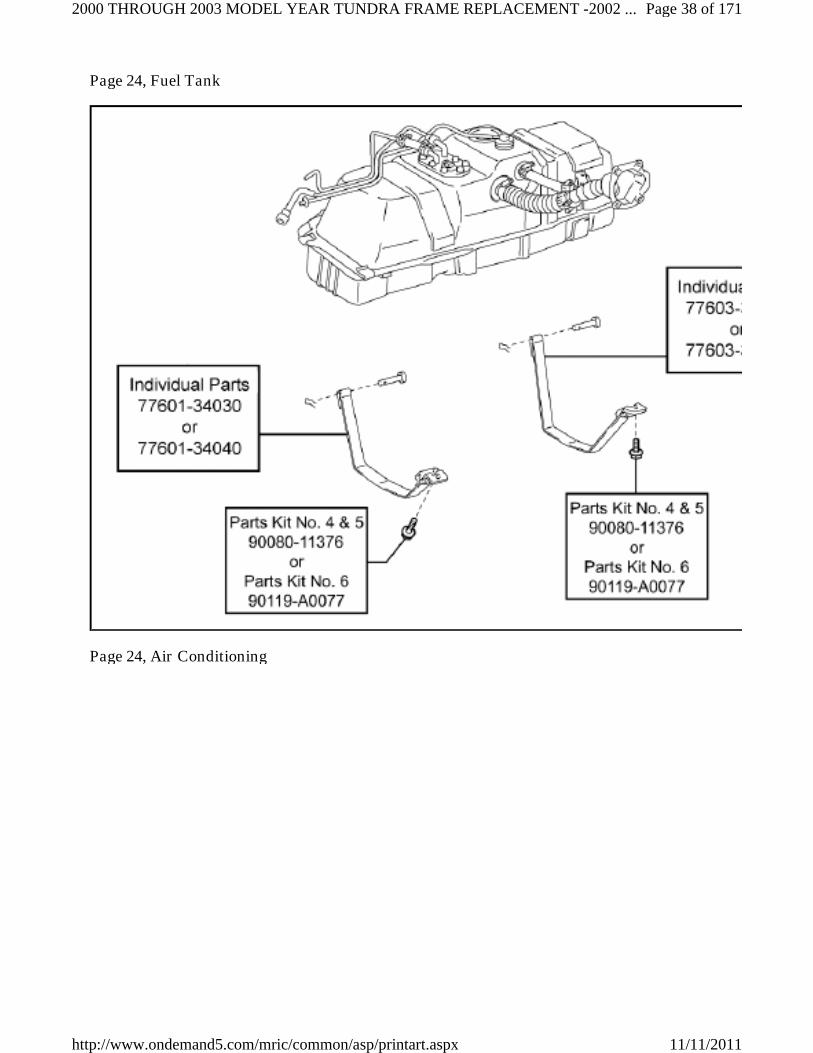
Page 24, Fuel Tank
Page 24, Air Conditioning
Page 38 of 1712000 THROUGH 2003 MODEL YEAR TUNDRA FRAME REPLACEMENT -2002 ...
11/11/2011http://www.ondemand5.com/mric/common/asp/printart.aspx

Page 25, AT Shift Cable/Radiator
Page 25, Front Bumper
Page 39 of 1712000 THROUGH 2003 MODEL YEAR TUNDRA FRAME REPLACEMENT -2002 ...
11/11/2011http://www.ondemand5.com/mric/common/asp/printart.aspx

Page 25, Rear Bumper
Page 40 of 1712000 THROUGH 2003 MODEL YEAR TUNDRA FRAME REPLACEMENT -2002 ...
11/11/2011http://www.ondemand5.com/mric/common/asp/printart.aspx

III. FRAME INSPECTION
PERFORM INITIAL PRE-HOIST INSPECTION1.
Page 41 of 1712000 THROUGH 2003 MODEL YEAR TUNDRA FRAME REPLACEMENT -2002 ...
11/11/2011http://www.ondemand5.com/mric/common/asp/printart.aspx
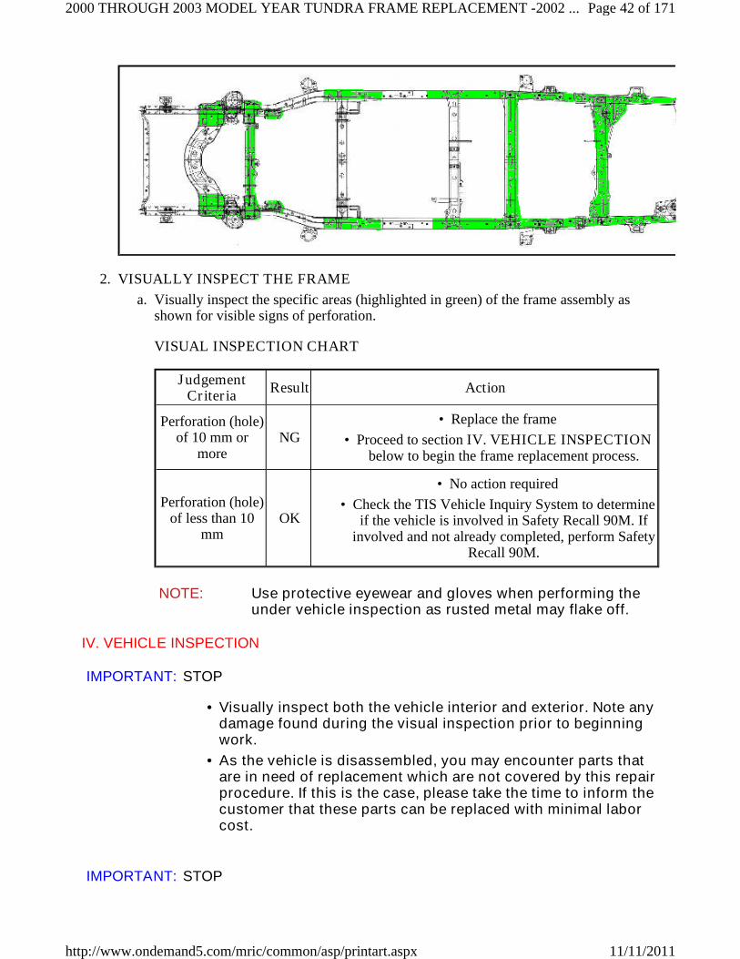
VISUALLY INSPECT THE FRAME2.
Visually inspect the specific areas (highlighted in green) of the frame assembly asshown for visible signs of perforation.
a.
VISUAL INSPECTION CHART
JudgementCriteria
Result Action
Perforation (hole)of 10 mm or
moreNG
Replace the frame•
Proceed to section IV. VEHICLE INSPECTIONbelow to begin the frame replacement process.
•
Perforation (hole)of less than 10
mmOK
No action required•
Check the TIS Vehicle Inquiry System to determineif the vehicle is involved in Safety Recall 90M. If
involved and not already completed, perform SafetyRecall 90M.
•
NOTE: Use protective eyewear and gloves when performing theunder vehicle inspection as rusted metal may flake off.
IV. VEHICLE INSPECTION
IMPORTANT: STOP
Visually inspect both the vehicle interior and exterior. Note anydamage found during the visual inspection prior to beginningwork.
•
As the vehicle is disassembled, you may encounter parts thatare in need of replacement which are not covered by this repairprocedure. If this is the case, please take the time to inform thecustomer that these parts can be replaced with minimal laborcost.
•
IMPORTANT: STOP
Page 42 of 1712000 THROUGH 2003 MODEL YEAR TUNDRA FRAME REPLACEMENT -2002 ...
11/11/2011http://www.ondemand5.com/mric/common/asp/printart.aspx

Due to the size and weight of the frame, only above-ground lifts areto be utilized when performing the frame replacement on 2000 - 2003Tundra Vehicles. If a dealership is not equipped with abovegroundlifts, the frame replacement may need to be sublet to a body shop orother dealership business.
V. FRAME REPLACEMENT WORK PROCEDURE
A. SAFETY CHECKLIST & PRECAUTIONS WHEN DRAINING THE FUEL SYSTEM
IMPORTANT: STOP
Always remember "SAFETY FIRST" .•
Be extremely careful when handling fuel to prevent fires fromoccurring.
•
Before beginning work on the fuel system, perform thefollowing safety check list.
•
Before removing any fuel system part, drain all fuel to preventspilling.
•
AIR VENTILATION1.
Perform work in a well ventilated area.•
DO NOT work underground or in an area where fuel vapors may fill the room due topoor ventilation.
•
Quickly clean up any spilled fuel with a dry cloth and dissipate the fuel vapors.•
Dry all cloths that have come in contact with fuel in a well ventilated area and disposeof them properly (according to applicable local regulations).
•
FIRES AND IGNITION SOURCES ARE STRICTLY PROHIBITED2.
Fires and ignition sources are prohibited while working on the fuel system.•
Clearly display the sign found on the next page stating "WORKING WITHGASOLINE, NO FIRES OR IGNITION SOURCES".
•
Smoking is prohibited near the work area.•
DO NOT work in areas where there are welders, grinders, drills, electric motors,heaters, etc.
•
DO NOT use work lamps or any other electrical appliance due to the risk of sparksflying from the power switch or a rise in temperature.
•
DO NOT use metal hammers while working, due to the risk of flying sparks.•
DO NOT start any engines or perform any of the above in neighboring work bays.•
FIRE EXTINGUISHER3.
Have a fire extinguisher ready and available before beginning work.•
PREVENT STATIC ELECTRICITY4.
To help prevent static electricity, lightly wet the floor with water, but not to the pointwhere it creates a hazardous working condition.
•
Page 43 of 1712000 THROUGH 2003 MODEL YEAR TUNDRA FRAME REPLACEMENT -2002 ...
11/11/2011http://www.ondemand5.com/mric/common/asp/printart.aspx

Place appropriate warning cones or stand signs around the area as a caution.•
PRECAUTIONS WHEN USING A LIFT5.
For bays equipped with auto lifts, cover all access cover joints with duct tape.•
In the event that fuel has leaked inside the auto lift, remove the access cover and cleanup any spilled fuel. Dissipate fuel vapors until the smell is gone.
•
PREVENT THE FUEL FROM SPRAYING6.
When disconnecting any fuel tubes, pipes, hoses or connectors there may still be somepressure remaining, even after discharging the system. To prevent the fuel fromspraying, cover the tubes, pipes or connectors with a shop rag before disconnecting.
•
Remember to always wear protective goggles especially when disconnecting fueltubes, pipes, hoses or connectors.
•
PREVENT THE FUEL FROM CONTACTING OTHER PARTS7.
Do not allow the fuel to come in contact with any parts made of rubber or leather.•
ASSIGN A SAFETY SUPERVISOR8.
Assign a safety supervisor to be in charge of all safety precautions and fire hazardsaround the work area.
•
Page 44 of 1712000 THROUGH 2003 MODEL YEAR TUNDRA FRAME REPLACEMENT -2002 ...
11/11/2011http://www.ondemand5.com/mric/common/asp/printart.aspx

B. REMOVE THE BED ASSY.
IMPORTANT: STOP
If the frame is perforated, ONLY raise the vehicle high enoughto remove the tires.
•
For added safety and support place jack stands under the frontand rear portions of the frame.
•
DO NOT work directly underneath the vehicle when performingbed assy. removal.
•
The actual vehicle specs, equipment and parts required maydiffer than what is shown. Please use the correctspecifications and parts for the model you are working on.
•
For additional repair information, please reference to theappropriate repair manual found on TIS for the vehicle you areworking on.
•
CENTER THE VEHICLE BETWEEN THE LIFT ARMS1.
Page 45 of 1712000 THROUGH 2003 MODEL YEAR TUNDRA FRAME REPLACEMENT -2002 ...
11/11/2011http://www.ondemand5.com/mric/common/asp/printart.aspx

Verify the vehicle is aligned with the center point of the lift to prevent interferenceand damage to the frame and/or lift.
a.
REMOVE THE FOLLOWING PARTS2.
License Plate Lights•
Center Rear Bumper Pad•
Rear Bumper Assy•
Trailer Hitch (If Equipped)•
Rear Mudguards (If Equipped)•
Side Step Assy (If Equipped)•
Fuel Tank Filler Pipe Shield•
REMOVE THE WIRE HARNESS3.
Disconnect the connectors.a.
Disconnect the clamps and the frame wire harness from the bed assembly.b.
NOTE: The number of connectors may differ depending onthe vehicle specification.
•
Be careful not to damage the wire harness clampswhen removing them.
•
DISCONNECT THE FUEL INLET PIPE4.
Page 46 of 1712000 THROUGH 2003 MODEL YEAR TUNDRA FRAME REPLACEMENT -2002 ...
11/11/2011http://www.ondemand5.com/mric/common/asp/printart.aspx

Remove the 2 nuts and disconnect the fuel inlet pipe.a.
REMOVE THE BED ASSEMBLY5.
Page 47 of 1712000 THROUGH 2003 MODEL YEAR TUNDRA FRAME REPLACEMENT -2002 ...
11/11/2011http://www.ondemand5.com/mric/common/asp/printart.aspx

Using a Torx® T55H Tamper Resistant Socket, remove the Torx® bolts from the bedassembly
a.
Regular Cab: 8 Torx® bolts ◦
Access Cab: 6 Torx® bolts ◦
NOTE: Use 4 or more people to remove the bedassembly from the frame.
•
Evenly support the bed assembly whenremoving it.
•
C. DISCHARGE THE FUEL SYSTEM PRESSURE
IMPORTANT: STOP
DO NOT disconnect any part of the fuel system until you havedischarged the fuel system pressure.
•
Even after discharging the fuel system pressure, place a pieceof cloth around the tubes, pipe, hoses and connectors as youseparate them to reduce the risk of fuel spraying on yourself,in the engine compartment and onto other parts.
•
For additional repair information, please reference to theappropriate repair manual in TIS for the vehicle you areworking on.
•
CHECK FOR DTCs1.
DISCHARGE THE FUEL SYSTEM PRESSURE2.
Page 48 of 1712000 THROUGH 2003 MODEL YEAR TUNDRA FRAME REPLACEMENT -2002 ...
11/11/2011http://www.ondemand5.com/mric/common/asp/printart.aspx

Disconnect the fuel pump connector.a.
Start the engine.b.
After the engine has stopped, turn the ignition switch OFF.c.
Crank the engine again to check that it does not start.d.
NOTE: Please make sure to follow the procedure listed above.This will prevent a large amount of gasoline from spillingout when high pressure fuel tube is disconnected.
RECORD THE RADIO STATION PRESETS & REMOVE THE BATTERY3.
NOTE: Wait 90 seconds after the negative (-) terminal cable isdisconnected from the battery before proceeding. Doing so willprevent the SRS from being deployed (i.e. airbag, seat beltpretensioner, etc.).
D. REMOVE THE CAB BODY ASSY
IMPORTANT: STOP
Page 49 of 1712000 THROUGH 2003 MODEL YEAR TUNDRA FRAME REPLACEMENT -2002 ...
11/11/2011http://www.ondemand5.com/mric/common/asp/printart.aspx

If the frame is perforated, ONLY raise the vehicle high enoughto remove the tires.
•
For added safety and support place jack stands under the frontand rear portions of the frame.
•
DO NOT work directly underneath the vehicle when performingcab body assy removal, unless noted.
•
The actual vehicle specs, equipment and parts required maydiffer than what is shown. Please use the correct specs andparts for the model you are working on.
•
For additional repair information, please reference to theappropriate repair manual in TIS for the vehicle you areworking on.
•
REMOVE THE ENGINE UNDER COVERS1.
NOTE: Use precaution when performing this step, as you will need towork underneath the vehicle.
EVACUATE THE REFRIGERANT FROM THE AIR CONDITIONING SYSTEM2.
DRAIN THE FOLLOWING FLUIDS3.
Coolant•
Clutch Fluid (Manual Transmission Vehicles Only)•
Brake Fluid•
NOTE: DO NOT remove the radiator cap while the radiator andengine are hot, doing so may cause the coolant to sprayout causing potential injuries.
DISCONNECT THE SHIFT CABLE4.
Page 50 of 1712000 THROUGH 2003 MODEL YEAR TUNDRA FRAME REPLACEMENT -2002 ...
11/11/2011http://www.ondemand5.com/mric/common/asp/printart.aspx

Page 51 of 1712000 THROUGH 2003 MODEL YEAR TUNDRA FRAME REPLACEMENT -2002 ...
11/11/2011http://www.ondemand5.com/mric/common/asp/printart.aspx

NOTE: Use precaution when performing this step, as you will need towork underneath the vehicle.
Remove the pin and washer.a.
Remove the bolt(s) and disconnect the shift cable.b.
NOTE: If the pin is difficult to remove, remove the nut and thenthe cable.
DISCONNECT THE NO. 1 PARKING BRAKE CABLE5.
Page 52 of 1712000 THROUGH 2003 MODEL YEAR TUNDRA FRAME REPLACEMENT -2002 ...
11/11/2011http://www.ondemand5.com/mric/common/asp/printart.aspx

Page 53 of 1712000 THROUGH 2003 MODEL YEAR TUNDRA FRAME REPLACEMENT -2002 ...
11/11/2011http://www.ondemand5.com/mric/common/asp/printart.aspx

NOTE: Use precaution when performing this step, as you will need towork underneath the vehicle.
For Automatic Transmission Vehicles
Loosen the nut and separate the No.1 parking brake cable assy.a.
Remove the clip and the No.1 parking brake cable assembly.b.
For Manual Transmission Vehicles
Remove the clip and lever pivot pin.a.
Remove the clip and the No.1 parking brake cable assembly.b.
DISCONNECT THE NO.1 FUEL HOSE6.
NOTE: Use precaution when performing this step, as you will need towork underneath the vehicle.
Remove the clip and disconnect the No.1 fuel hose.a.
DISCONNECT THE REAR BRAKE TUBES7.
Page 54 of 1712000 THROUGH 2003 MODEL YEAR TUNDRA FRAME REPLACEMENT -2002 ...
11/11/2011http://www.ondemand5.com/mric/common/asp/printart.aspx

NOTE: Use precaution when performing this step, as you will need towork underneath the vehicle.
Disconnect the 2 rear brake tubes.a.
DISCONNECT THE CLUTCH MASTER CYLINDER TUBE (MANUALTRANSMISSION VEHICLES ONLY)
8.
Page 55 of 1712000 THROUGH 2003 MODEL YEAR TUNDRA FRAME REPLACEMENT -2002 ...
11/11/2011http://www.ondemand5.com/mric/common/asp/printart.aspx

NOTE: Use precaution when performing this step, as you will need towork underneath the vehicle.
Disconnect the clutch master cylinder tube.a.
Remove the clip and disconnect the clutch hose.b.
REMOVE THE FOLLOWING PARTS9.
Front Wheels•
Front Bumper Assy•
Radiator•
NOTE: After disconnecting the automatic transmission oil coolerhoses, plug them and cap the fittings to prevent the ATFfrom spilling out (Automatic Transmission Vehicles Only) .
REMOVE THE OIL COOLER PIPE (2UZ-FE ONLY)10.
Page 56 of 1712000 THROUGH 2003 MODEL YEAR TUNDRA FRAME REPLACEMENT -2002 ...
11/11/2011http://www.ondemand5.com/mric/common/asp/printart.aspx

Disconnect the hose.a.
Remove the bolt and the oil cooler pipe.b.
REMOVE THE FOLLOWING PARTS11.
Throttle Body Cover (2UZ-FE Only)•
Air Cleaner Case Assy & Hose•
DISCONNECT THE FOLLOWING PARTS12.
Accelerator Cable, Engine Side (Only For Vehicles Produced On Or Before August2002)
•
Cruise Control Cable (If Equipped)•
DISCONNECT THE HOSES13.
Page 57 of 1712000 THROUGH 2003 MODEL YEAR TUNDRA FRAME REPLACEMENT -2002 ...
11/11/2011http://www.ondemand5.com/mric/common/asp/printart.aspx

Page 58 of 1712000 THROUGH 2003 MODEL YEAR TUNDRA FRAME REPLACEMENT -2002 ...
11/11/2011http://www.ondemand5.com/mric/common/asp/printart.aspx

Disconnect the brake booster hose.a.
Disconnect the EVAP hose(s).b.
Disconnect the vacuum hose (5VZ-FE Only).c.
Disconnect the A.D.D. vacuum hose (5VZ-FE 4WD Only).d.
NOTE: The number of hoses will differ depending on the vehiclespecification.
DISCONNECT THE NO.2 ENGINE WIRE HARNESS14.
Remove the relay block cover.a.
Disconnect the connector and clamp.b.
Remove the bolt and disconnect the ground wire.c.
Remove the 2 nuts and disconnect the (+) positive battery cable.d.
Remove the clip and disconnect the No.2 engine wire harness.e.
Page 59 of 1712000 THROUGH 2003 MODEL YEAR TUNDRA FRAME REPLACEMENT -2002 ...
11/11/2011http://www.ondemand5.com/mric/common/asp/printart.aspx

DISCONNECT THE NO.1 FUEL HOSE (ONLY FOR VEHICLES PRODUCED ONOR BEFORE AUGUST 2002)
15.
DISCONNECT THE VANE PUMP OIL RESERVOIR (2UZ-FE ONLY)16.
Page 60 of 1712000 THROUGH 2003 MODEL YEAR TUNDRA FRAME REPLACEMENT -2002 ...
11/11/2011http://www.ondemand5.com/mric/common/asp/printart.aspx

Remove the 2 nuts and disconnect the vane pump oil reservoir.a.
DISCONNECT THE FOLLOWING PARTS17.
A/C Compressor Discharge & Suction Hoses•
Water/Heater Hoses, Engine Side•
DISCONNECT THE ENGINE WIRE HARNESS18.
Page 61 of 1712000 THROUGH 2003 MODEL YEAR TUNDRA FRAME REPLACEMENT -2002 ...
11/11/2011http://www.ondemand5.com/mric/common/asp/printart.aspx

Remove the bolt and the ground wire.a.
Remove the bolt.b.
Remove the 2 nuts holding the engine wire harness container from the cowl panel.c.
Remove the glove box.d.
Remove the lower No. 2 finish panel.e.
Remove the No. 4 heat register duct.f.
Disconnect the connectors and clamp.g.
Page 62 of 1712000 THROUGH 2003 MODEL YEAR TUNDRA FRAME REPLACEMENT -2002 ...
11/11/2011http://www.ondemand5.com/mric/common/asp/printart.aspx

NOTE: The number of connectors will differ depending on the vehiclespecification.
DISCONNECT THE FRAME WIRE HARNESS CONNECTOR19.
Page 63 of 1712000 THROUGH 2003 MODEL YEAR TUNDRA FRAME REPLACEMENT -2002 ...
11/11/2011http://www.ondemand5.com/mric/common/asp/printart.aspx

Remove the left front door scuff plate.a.
Remove the left access cab door scuff plate (Access Cab Only).b.
Remove the left front cowl side trim panel.c.
Disconnect the frame wire harness connector(s).d.
Remove the frame wire harness grommet from the cab assy.e.
Pull out the frame wire harness from the cab assy.f.
NOTE: The number of connectors will differ depending on thevehicle spec.
DISCONNECT THE OXYGEN SENSOR WIRE HARNESS CONNECTOR (5VZ-FEONLY)
20.
Page 64 of 1712000 THROUGH 2003 MODEL YEAR TUNDRA FRAME REPLACEMENT -2002 ...
11/11/2011http://www.ondemand5.com/mric/common/asp/printart.aspx

Remove the right front door scuff plate.a.
Remove the right access cab door scuff plate (Access Cab Only).b.
Remove the right front cowl side trim panel.c.
Disconnect the oxygen sensor wire harness connector.d.
Remove the oxygen sensor wire harness grommet from the cab assy.e.
Pull out the oxygen sensor wire harness from the cab assy.f.
REMOVE THE FOLLOWING PARTS21.
Manual Transmission Shift Lever (Manual Transmission Vehicles Only)•
Transfer Case Shift Lever (5VZ-FE 4WD Only)•
REMOVE THE FRONT FENDER APRON SEAL22.
Page 65 of 1712000 THROUGH 2003 MODEL YEAR TUNDRA FRAME REPLACEMENT -2002 ...
11/11/2011http://www.ondemand5.com/mric/common/asp/printart.aspx

Page 66 of 1712000 THROUGH 2003 MODEL YEAR TUNDRA FRAME REPLACEMENT -2002 ...
11/11/2011http://www.ondemand5.com/mric/common/asp/printart.aspx

Remove the 21 clips and 4 front fender apron seals.a.
DISCONNECT THE FRONT BRAKE TUBES23.
Page 67 of 1712000 THROUGH 2003 MODEL YEAR TUNDRA FRAME REPLACEMENT -2002 ...
11/11/2011http://www.ondemand5.com/mric/common/asp/printart.aspx

Page 68 of 1712000 THROUGH 2003 MODEL YEAR TUNDRA FRAME REPLACEMENT -2002 ...
11/11/2011http://www.ondemand5.com/mric/common/asp/printart.aspx

Disconnect the front brake tube.a.
Repeat the procedure on the opposite side.b.
DISCONNECT THE FRONT SPEED SENSOR CONNECTORS (ABS EQUIPPEDVEHICLES ONLY)
24.
Page 69 of 1712000 THROUGH 2003 MODEL YEAR TUNDRA FRAME REPLACEMENT -2002 ...
11/11/2011http://www.ondemand5.com/mric/common/asp/printart.aspx

Page 70 of 1712000 THROUGH 2003 MODEL YEAR TUNDRA FRAME REPLACEMENT -2002 ...
11/11/2011http://www.ondemand5.com/mric/common/asp/printart.aspx

Disconnect the harness clamp and front speed sensor connector.a.
Repeat the procedure on the opposite side.b.
REINSTALL THE FRONT WHEELS25.
DISCONNECT THE NO. 2 INTERMEDIATE SHAFT26.
Page 71 of 1712000 THROUGH 2003 MODEL YEAR TUNDRA FRAME REPLACEMENT -2002 ...
11/11/2011http://www.ondemand5.com/mric/common/asp/printart.aspx

Page 72 of 1712000 THROUGH 2003 MODEL YEAR TUNDRA FRAME REPLACEMENT -2002 ...
11/11/2011http://www.ondemand5.com/mric/common/asp/printart.aspx

NOTE: Use precaution when performing this step, as you will need towork underneath the vehicle.
Make sure the front wheels are in a straight-ahead position and the steering wheel iscentered.
a.
Using the seat belt, hold the steering wheel in position as shown in the illustration, inorder to prevent damage to the spiral cable.
b.
Place matchmarks on the No. 2 intermediate shaft and control valve shaft.c.
Loosen bolt "A" and remove bolt "B".d.
Disconnect the No. 2 intermediate shaft from the control valve shaft.e.
NOTE: If the No. 2 intermediate shaft assembly is stuck, tap itfrom below with a brass hammer to disconnect it.
REMOVE THE CAB BODY ASSEMBLY USING AN ABOVE GROUND LIFT27.
Page 73 of 1712000 THROUGH 2003 MODEL YEAR TUNDRA FRAME REPLACEMENT -2002 ...
11/11/2011http://www.ondemand5.com/mric/common/asp/printart.aspx

Remove the 6 nuts and 6 washers.a.
Set the lift arms under the cab body assembly so they DO NOT interfere with theframe or cab mounts.
b.
Check that all wire harnesses, hoses, cables and the steering shaft are disconnected.c.
Lift the cab assembly up slowly, making sure it does not interfere with anything whilebeing raised.
d.
Raise the cab assembly high enough so that the top of the engine clears the lowestpoint of the cab assy.
e.
Pull the frame assembly out from under the vehicle.f.
Lower the cab assembly all the way down and leave it on the lift.g.
NOTE: Center the cab assembly weight on the lift arms sothat it does not slant/tilt to one side.
•
Raise the cab assembly slightly off the frame andverify that it is held securely by the lift arms.
•
DO NOT work directly underneath the vehicle whenpulling the frame assembly out from under.
•
Page 74 of 1712000 THROUGH 2003 MODEL YEAR TUNDRA FRAME REPLACEMENT -2002 ...
11/11/2011http://www.ondemand5.com/mric/common/asp/printart.aspx

DO NOT remove the cab mount bolts, as they will beused as guides during cab assembly reinstallationprocess.
•
E. DISASSEMBLE THE FRAME
PLACE THE FRAME ON A LIFT1.
Place the frame on the lift, and secure it with a ratcheting tie down strap. This willprevent the frame from tilting or falling off as parts are removed.
a.
Ratcheting Tie Downs: Qty 1•
Length: 2 in X 27 ft•
Minimum Work Load Capacity: 3,000 lbs•
REMOVE THE FOLLOWING PARTS2.
Spare Tire•
Front Propeller Shaft (4WD Only)•
Rear Propeller Shaft•
Insert SST 09325-40010 into the transmission after the rear propeller shaft isremoved to prevent oil leakage (2WD Only)
•
NOTE: Make sure to place matchmarks on the front (ifequipped) and rear propeller shafts prior to removal.
REMOVE THE EXHAUST SYSTEM3.
Page 75 of 1712000 THROUGH 2003 MODEL YEAR TUNDRA FRAME REPLACEMENT -2002 ...
11/11/2011http://www.ondemand5.com/mric/common/asp/printart.aspx

Disconnect the oxygen sensor wire harness clamp (5VZ-FE Only).a.
Remove the 4 bolts and 2 flange retainers (2UZ-FE Only).b.
Remove the 2 bolts and flange retainer (5VZ-FE Only).c.
Remove the exhaust and exhaust pipe supports.d.
Remove the exhaust pipe gasket(s).e.
DISCONNECT THE REAR SPEED SENSOR CONNECTOR (ABS EQUIPPEDVEHICLES ONLY)
4.
Page 76 of 1712000 THROUGH 2003 MODEL YEAR TUNDRA FRAME REPLACEMENT -2002 ...
11/11/2011http://www.ondemand5.com/mric/common/asp/printart.aspx

Remove the nut and disconnect the rear speed sensor connector.a.
REMOVE THE FOLLOWING PARTS5.
Fuel Tank Straps•
Fuel Tank•
Charcoal Canister Assy (Only For Vehicles Produced After August 2002)•
DISCONNECT THE FUEL TUBES AND HOSES6.
For 2UZ-FE Vehicles:
Page 77 of 1712000 THROUGH 2003 MODEL YEAR TUNDRA FRAME REPLACEMENT -2002 ...
11/11/2011http://www.ondemand5.com/mric/common/asp/printart.aspx

Remove the pulsation dumper with SST 09612-24011, and disconnect the fuel mainhose.
a.
Remove the 2 gaskets.b.
Remove the clip and disconnect the fuel return hose.c.
NOTE: Put a shop towel under the delivery pipe to catch anyspilled fuel.
•
Slowly loosen the pulsation dumper.•
For 5VZ-FE Vehicles:
Page 78 of 1712000 THROUGH 2003 MODEL YEAR TUNDRA FRAME REPLACEMENT -2002 ...
11/11/2011http://www.ondemand5.com/mric/common/asp/printart.aspx

Page 79 of 1712000 THROUGH 2003 MODEL YEAR TUNDRA FRAME REPLACEMENT -2002 ...
11/11/2011http://www.ondemand5.com/mric/common/asp/printart.aspx

Remove the bolt and wire harness clamp (Illustration "A").a.
Remove the bracket bolt (Illustration "B").b.
Remove the union bolt and the main fuel pipe (Illustration "B").c.
Remove the 2 gaskets (Illustration "B").d.
Remove the clip and disconnect the fuel return hose (Illustration "B").e.
REMOVE AND SET ASIDE THE POWER STEERING PUMP ASSY7.
Remove the drive belt.a.
Disconnect the connector (5VZ-FE Only).b.
Remove the 2 bolts and the nut (2UZ-FE Only) or the bolt and the nut (5VZ-FEOnly) and the power steering vane pump.
c.
NOTE: DO NOT disconnect the power steering pump hosesor tubes.
•
Make sure to keep the power steering pumpreservoir in an upright position to prevent the fluidfrom leaking out.
•
REMOVE THE ENGINE AND TRANSMISSION ASSY (5VZ-FE ONLY)8.
Page 80 of 1712000 THROUGH 2003 MODEL YEAR TUNDRA FRAME REPLACEMENT -2002 ...
11/11/2011http://www.ondemand5.com/mric/common/asp/printart.aspx

Disconnect and remove the necessary items/parts to prepare the engine andtransmission assy for removal.
a.
Install the engine hanger.b.
For Vehicles Produced On Or Before August 2002):
12282-62050 = Engine Hanger No. 1, Qty: 1
90080-11443 = Bolt, Qty: 1
For Vehicles Produced After August 2002):
12282-62070 = Engine Hanger No. 1, Qty: 1
90119-10684 (90080-11443) = Bolt, Qty: 2
Remove the engine and transmission assy.c.
Page 81 of 1712000 THROUGH 2003 MODEL YEAR TUNDRA FRAME REPLACEMENT -2002 ...
11/11/2011http://www.ondemand5.com/mric/common/asp/printart.aspx

NOTE: When removing the engine and transmission assy,ALWAYS use 2 engine hoists or mini cranes to lift it.
•
DO NOT use 1 engine hoist or mini crane to lift the engineand transmission assy, as the unbalanced weight maylead to an accident or injury.
•
ONLY use engine hoists or mini cranes that can properlysupport the weight of the engine and transmission assy.
•
Carefully adjust the 2 engine hoists or mini cranes usedso that the engine and transmission assy is properlybalanced.
•
Page 82 of 1712000 THROUGH 2003 MODEL YEAR TUNDRA FRAME REPLACEMENT -2002 ...
11/11/2011http://www.ondemand5.com/mric/common/asp/printart.aspx

REMOVE THE WHEELS9.
DISCONNECT THE FRONT BRAKE HOSE10.
Page 83 of 1712000 THROUGH 2003 MODEL YEAR TUNDRA FRAME REPLACEMENT -2002 ...
11/11/2011http://www.ondemand5.com/mric/common/asp/printart.aspx

Disconnect the front brake tube from the brake hose.a.
Remove the clip and disconnect the front brake hose.b.
Repeat the procedure on the opposite side.c.
DISCONNECT THE FRONT SPEED SENSOR WIRE HARNESS (ABS EQUIPPEDVEHICLES ONLY)
11.
Page 84 of 1712000 THROUGH 2003 MODEL YEAR TUNDRA FRAME REPLACEMENT -2002 ...
11/11/2011http://www.ondemand5.com/mric/common/asp/printart.aspx

Remove the 2 bolts, 2 clamps and the connector.a.
Repeat the procedure on the opposite side.b.
REMOVE THE FOLLOWING PARTS12.
Front Stabilizer Bar•
Front Axle Shaft Nut (4WD Only)•
The Tie Rod End•
Remove the cotter pin and nut.•
Using the SST 09610-20012, disconnect the tie rod end.•
Lower Ball Joint•
Remove the cotter pin and nut.•
Using the SST 09628-62011, disconnect the lower ball joint.•
REMOVE THE FRONT SUSPENSION UPPER ARM AND STEERING KNUCKLEASSY
13.
Page 85 of 1712000 THROUGH 2003 MODEL YEAR TUNDRA FRAME REPLACEMENT -2002 ...
11/11/2011http://www.ondemand5.com/mric/common/asp/printart.aspx

Remove the bolt, nut, 2 washers and front suspension upper arm w/steering knuckle.a.
Repeat the procedure on the opposite side.b.
NOTE: If the drive shaft is difficult to disconnect, tap the driveshaft loose with a plastic hammer.
DRAIN THE FRONT DIFFERENTIAL OIL (4WD ONLY)14.
REMOVE THE FOLLOWING PARTS15.
Front Shock Absorber•
Power Steering Link Assembly w/Power Steering Vane Pump•
Front Drive Shaft (4WD Only)•
Front Differential Carrier (4WD Only)•
NOTE: When removing the power steering link with the vanepump attached, have one person support the powersteering link and the other support the vane pump.
•
Make sure to keep the power steering pumpreservoir in an upright position to prevent the fluidfrom leaking out.
•
Page 86 of 1712000 THROUGH 2003 MODEL YEAR TUNDRA FRAME REPLACEMENT -2002 ...
11/11/2011http://www.ondemand5.com/mric/common/asp/printart.aspx

If the drive shaft is difficult to remove tap it with aplastic hammer.
•
Be careful not to damage the dust cover and oil seal.•
REMOVE THE NO.2 PARKING BRAKE CABLE16.
Remove the No. 2 parking brake cable adjustment nut (Manual TransmissionVehicles Only).
a.
Remove the clip.b.
Remove the 2 clips and 2 pins.c.
Remove the 4 bolts and No.2 parking brake cable.d.
REMOVE THE PARKING BRAKE INTERMEDIATE LEVER (MANUALTRANSMISSION VEHICLES ONLY)
17.
DISCONNECT THE LOAD SENSING SPRING ASSY (LSPV EQUIPPEDVEHICLES ONLY)
18.
Page 87 of 1712000 THROUGH 2003 MODEL YEAR TUNDRA FRAME REPLACEMENT -2002 ...
11/11/2011http://www.ondemand5.com/mric/common/asp/printart.aspx

Remove the bolt, washer, nut and disconnect the load sensing spring assy.a.
DISCONNECT THE BRAKE HOSE19.
Page 88 of 1712000 THROUGH 2003 MODEL YEAR TUNDRA FRAME REPLACEMENT -2002 ...
11/11/2011http://www.ondemand5.com/mric/common/asp/printart.aspx

Disconnect the No.4 rear brake tube.a.
Remove the clip and disconnect the brake hose.b.
REMOVE THE FOLLOWING PARTS20.
Rear Stabilizer Bar (If Equipped)•
Rear Shock Absorbers•
Rear Differential Assy•
Spare Tire Carrier•
REMOVE THE FRAME WIRE HARNESS21.
Page 89 of 1712000 THROUGH 2003 MODEL YEAR TUNDRA FRAME REPLACEMENT -2002 ...
11/11/2011http://www.ondemand5.com/mric/common/asp/printart.aspx

Remove the bolt and disconnect the ground wire (If Equipped).a.
Disconnect the clamps and remove the frame wire harness.b.
NOTE: The number of wire harness clamps will differdepending on the vehicle specification.
•
Take care not to damage or break the wire harnessclamps during removal.
•
REMOVE THE FUEL TUBES22.
Page 90 of 1712000 THROUGH 2003 MODEL YEAR TUNDRA FRAME REPLACEMENT -2002 ...
11/11/2011http://www.ondemand5.com/mric/common/asp/printart.aspx

Remove the bolts, clamps and fuel tubes.a.
NOTE: The number of fuel tube clamps will differ dependingon the vehicle specification.
•
If the fuel tube clamp(s) are damaged replace them.•
REMOVE THE CHARCOAL CANISTER VENT HOSE (ONLY FOR VEHICLESPRODUCED ON OR BEFORE AUGUST 2002)
23.
Page 91 of 1712000 THROUGH 2003 MODEL YEAR TUNDRA FRAME REPLACEMENT -2002 ...
11/11/2011http://www.ondemand5.com/mric/common/asp/printart.aspx

Remove the charcoal canister vent hose and plug.a.
REMOVE THE STUD BOLT24.
Page 92 of 1712000 THROUGH 2003 MODEL YEAR TUNDRA FRAME REPLACEMENT -2002 ...
11/11/2011http://www.ondemand5.com/mric/common/asp/printart.aspx

REMOVE THE PARKING BRAKE CABLE SUPPORT BRACKET25.
Page 93 of 1712000 THROUGH 2003 MODEL YEAR TUNDRA FRAME REPLACEMENT -2002 ...
11/11/2011http://www.ondemand5.com/mric/common/asp/printart.aspx

Remove the 3 nuts and parking brake cable support bracket.a.
REMOVE THE CLIPS26.
Page 94 of 1712000 THROUGH 2003 MODEL YEAR TUNDRA FRAME REPLACEMENT -2002 ...
11/11/2011http://www.ondemand5.com/mric/common/asp/printart.aspx

REMOVE THE FOLLOWING PARTS27.
Transport/Toe Hooks (Qty: 2)•
Front Bumper reinforcement•
Front Suspension lower Arm•
Front Spring Bumper•
Cab Mounts (Qty: 6)•
Rear Leaf Springs•
REMOVE THE FRAME FROM THE LIFT28.
Remove the ratcheting tie down strap and the frame from the lift.a.
F. ASSEMBLE THE NEW FRAME
PLACE THE NEW FRAME ON THE LIFT1.
Place the NEW frame on the lift, and secure it with a ratcheting tie down strap. Thiswill prevent the frame from tilting or falling off as parts are installed.
a.
Ratcheting Tie Downs: Qty 1•
Length: 2 in X 27 ft•
Minimum Work Load Capacity: 3,000 lbs•
Page 95 of 1712000 THROUGH 2003 MODEL YEAR TUNDRA FRAME REPLACEMENT -2002 ...
11/11/2011http://www.ondemand5.com/mric/common/asp/printart.aspx

REAR LEAF SPRINGS PARTS INFORMATION
Part Number Part Name Kit # Qty
04483-0C030 Shackle Kit, Rear Spring NA(1) 2
90105-14132 Bolt 4-6 6
90179-14039 Nut 1-3 6
90201-14025 Washer 1-3 6(1) Individual part(s)
REINSTALL THE REAR LEAF SPRINGS2.
Reinstall the rear leaf spring with all NEW parts (shackle, bushings, bolts, washers &nuts) and torque to spec.
a.
Torque Spec: 170 N.m (1733 kgf.cm, 125 ft.lbf)
Repeat the procedure on the opposite side.b.
REINSTALL THE CAB MOUNTS3.
Page 96 of 1712000 THROUGH 2003 MODEL YEAR TUNDRA FRAME REPLACEMENT -2002 ...
11/11/2011http://www.ondemand5.com/mric/common/asp/printart.aspx

Reinstall cab mounts No. 1a.
Reinstall cab mounts No. 2 & No. 3 with 2 bolts each, and torque to spec.b.
Torque Spec: 61 N.m (622 kgf.cm, 45 ft.lbf)
Page 97 of 1712000 THROUGH 2003 MODEL YEAR TUNDRA FRAME REPLACEMENT -2002 ...
11/11/2011http://www.ondemand5.com/mric/common/asp/printart.aspx

REINSTALL THE CAB MOUNTS4.
Install the No.1 and No.2 front spring bumpers to the frame and torque to spec.a.
Torque Spec: 31 N.m (316 kgf.cm, 23 ft.lbf)
Repeat the procedure on the opposite side.b.
FRONT SUSPENSION LOWER ARM PARTS INFORMATION
Part Number Part Name Kit # Qty
48409-34020 Cam Sub-Assy, Front Suspension Toe Adjust 1-3 2
48409-34030 Cam Sub-Assy, Front Suspension Toe Adjust, No. 2 1-3 2
48452-35020 Plate, Front Suspension Toe Adjust, No. 2 1-3 4
90080-11275 Bolt 4-6 2
90080-11410 Bolt 4-6 2
Page 98 of 1712000 THROUGH 2003 MODEL YEAR TUNDRA FRAME REPLACEMENT -2002 ...
11/11/2011http://www.ondemand5.com/mric/common/asp/printart.aspx

REINSTALL THE FRONT SUSPENSION LOWER ARM5.
Reinstall the front suspension lower arm with 2 NEW bolts, 2 NEW toe adjustmentplates 2 NEW toe adjustment cam, then torque to spec.
a.
Torque Spec:
For Vehicles Produced On Or Before August 2002 - 130 N.m (1325 kgf.cm,95 ft.lbf)
•
For Vehicles Produced After August 2002 - 140 N.m (1427 kgf.cm, 103ft.lbf)
•
Repeat the procedure on the opposite side.b.
REINSTALL THE FOLLOWING PARTS6.
Front Bumper Reinforcement•
Reinstall with 4 NEW nuts.•
Torque Spec: 50 N.m (509 kgf.cm, 36 ft.lbf)•
Transport/Toe Hooks (Qty: 2)•
Torque Spec: 95 N.m (968 kgf.cm, 70 ft.lbf)•
FRONT BUMPER REINFORCEMENT PARTS INFORMATION
Part Number Part Name Kit # Qty
90178-10024 Nut 1-3 4
INSTALL THE NEW CLIPS7.
NEW CLIPS PARTS INFORMATION
Part Number Part Name Kit # Qty
90467-13076 Clip 1-3 2
Page 99 of 1712000 THROUGH 2003 MODEL YEAR TUNDRA FRAME REPLACEMENT -2002 ...
11/11/2011http://www.ondemand5.com/mric/common/asp/printart.aspx

REINSTALL THE PARKING BRAKE CABLE SUPPORT BRACKET8.
Page 100 of 1712000 THROUGH 2003 MODEL YEAR TUNDRA FRAME REPLACEMENT -200...
11/11/2011http://www.ondemand5.com/mric/common/asp/printart.aspx

Reinstall the parking brake cable support bracket with the 3 nuts, and torque to spec.a.
Torque Spec: 13 N.m (132 kgf.cm, 10 ft.lbf)
REINSTALL THE STUD BOLT9.
Page 101 of 1712000 THROUGH 2003 MODEL YEAR TUNDRA FRAME REPLACEMENT -200...
11/11/2011http://www.ondemand5.com/mric/common/asp/printart.aspx

Reinstall the stud bolt and torque to spec.a.
Torque Spec: 20 N.m (203 kgf.cm, 14 ft.lbf)
REINSTALL THE CHARCOAL CANISTER VENT HOSE (ONLY FOR VEHICLESPRODUCED ON OR BEFORE AUGUST 2002)
10.
Page 102 of 1712000 THROUGH 2003 MODEL YEAR TUNDRA FRAME REPLACEMENT -200...
11/11/2011http://www.ondemand5.com/mric/common/asp/printart.aspx

Reinstall the charcoal canister plug and vent hose.a.
REAR BRAKE TUBES PARTS INFORMATION
Part Number Part Name Kit # Qty
47323-0C011Tube, Rear Brake, No.3(2) NA(1) 1
47323-0C012 NA(1) 1
47324-0C011Tube, Rear Brake, No.4(2) 7, 9 1
47324-0C012 8, 10 1
47324-0C013 Tube, Rear Brake, No.4 with ABS 11 1
90949-01B60 Clamp, Brake Tube No. 6 1 5
90949-01B61Clamp, Brake Tube No. 7(2) 1 1
90949-01C33 2-3 1
90949-01C06 Clamp, Brake Tube No. 8 2-3 5
47361-0C011Tube, Rear Brake, No.10(2) NA(1) 1
47361-0C012 NA(1) 1
90904-12068 Way (for front brake tube) 1-3 1
90949-01B59Clamp(2) 1 1
90949-01C32 2-3 1
91621-B0816 Bolt 1-2 1
Page 103 of 1712000 THROUGH 2003 MODEL YEAR TUNDRA FRAME REPLACEMENT -200...
11/11/2011http://www.ondemand5.com/mric/common/asp/printart.aspx

Part Number Part Name Kit # Qty
90080-11180 Bolt - with ABS 9-11 1(1) Individual part(s)(2) Only 1 part is used. The part number varies depending on the Kit #
INSTALL THE NEW REAR BRAKE TUBES11.
Install the NEW rear brake tubes with the NEW clamp(s) and the NEW bolt, thentorque to spec.
a.
Torque Spec: Bolt - 28 N.m (285 kgf.cm, 20 ft.lbf)
Brake Tube - 15 N.m (153 kgf.cm, 11 ft.lbf)
REINSTALL THE CHARCOAL CANISTER TUBE (ONLY FOR VEHICLESPRODUCED AFTER AUGUST 2002)
12.
CHARCOAL CANISTER TUBE PARTS INFORMATION
Part Number Part Name Kit # Qty
77285-34280Clamp, Fuel Tube, No. 1
3 2
77285-34290 3 1
Page 104 of 1712000 THROUGH 2003 MODEL YEAR TUNDRA FRAME REPLACEMENT -200...
11/11/2011http://www.ondemand5.com/mric/common/asp/printart.aspx

Part Number Part Name Kit # Qty
77285-34300 3 1
77285-34310 3 1
90080-11180 Bolt 6 4
Reinstall the charcoal canister tube with NEW clamps and NEW bolts, then torque tospec.
a.
Torque Spec: 29 N.m (295 kgf.cm, 21 ft.lbf)
NOTE: The number of clamps will differ depending on the vehiclespec.
REINSTALL THE FUEL TUBES13.
Page 105 of 1712000 THROUGH 2003 MODEL YEAR TUNDRA FRAME REPLACEMENT -200...
11/11/2011http://www.ondemand5.com/mric/common/asp/printart.aspx

FUEL TUBES PARTS INFORMATION (2000 - 2002 MY)
Part Number Part Name Kit # Qty
77285-34030
Clamp, Fuel Tube, No. 1(1)
1 4
77285-34031 2 4
77285-34040 1 1
77285-34041 2 1
77285-34050 1 1
77285-34051 2 1
77285-34070 1 1
77285-34071 2 2
77285-34060Clamp, Fuel Tube, No. 1
1-2 2
77285-34080 1-2 1
90080-11180 Bolt 4-5 6(1) Only 1 part is used. The part number varies depending on the Kit #
FUEL TUBES PARTS INFORMATION (2003 MY)
Page 106 of 1712000 THROUGH 2003 MODEL YEAR TUNDRA FRAME REPLACEMENT -200...
11/11/2011http://www.ondemand5.com/mric/common/asp/printart.aspx

Part Number Part Name Kit # Qty
77285-34031
Clamp, Fuel Tube, No. 1
3 4
77285-34060 3 1
77285-34071 3 2
77285-34080 3 1
77285-34260 3 1
77285-34270 3 1
90080-11180 Bolt 6 6
Reinstall the fuel tubes with the NEW clamps and NEW bolts, then torque to spec.a.
Torque Spec: Filter Bracket Bolt - 20 N.m (203 kgf.cm, 14 ft.lbf)
Clamp Bolt - 29 N.m (295 kgf.cm, 21 ft.lbf)
NOTE: The number of clamps will differ depending on the vehiclespec.
REINSTALL THE FRAME WIRE HARNESS14.
Reconnect the clamps to reinstall the frame wire harness.a.
Reconnect the ground wire with the bolt and torque to spec.b.
Torque Spec: 30 N.m (305 kgf.cm, 22 ft.lbf)
NOTE: If the wire harness clamp(s) are damaged, repairthem following the steps below.
•
The number of wire harness clamps will differdepending on the vehicle spec.
•
PARTS INFORMATION (2000 - 2002 MY)
Part Number Part Name Kit # Qty
82711-1E320
Support, Wire Harness
1-2 1
82711-1E360 1-2 1
82711-21020 1-2 1
82711-26380 1-2 15
82711-3A640 1-2 1
82711-3F050 1-2 3
Page 107 of 1712000 THROUGH 2003 MODEL YEAR TUNDRA FRAME REPLACEMENT -200...
11/11/2011http://www.ondemand5.com/mric/common/asp/printart.aspx

PARTS INFORMATION (2003 MY)
Part Number Part Name Kit # Qty
82711-16830
Support, Wire Harness
3 3
82711-26380 3 15
82711-3A640 3 1
82711-3F050 3 3
Page 108 of 1712000 THROUGH 2003 MODEL YEAR TUNDRA FRAME REPLACEMENT -200...
11/11/2011http://www.ondemand5.com/mric/common/asp/printart.aspx

REPAIR PROCEDURE FOR CLAMP A
Remove the damaged clamp.a.
Install the NEW clamp to the frame wire harness connector.b.
Page 109 of 1712000 THROUGH 2003 MODEL YEAR TUNDRA FRAME REPLACEMENT -200...
11/11/2011http://www.ondemand5.com/mric/common/asp/printart.aspx

REPAIR PROCEDURE FOR CLAMP B, C & D
Remove the damaged clamp.a.
Install the NEW clamp to the frame wire harness with vinyl tape as shown in theillustration.
b.
REPAIR PROCEDURE FOR CLAMP E & F
Install the replacement NEW clamp to the frame in the direction shown in theillustration.
a.
Cut the damaged clamp as shown in the illustration.b.
Route the clamp through the cutout area of the damaged clamp and fasten securely.c.
REINSTALL THE FOLLOWING PARTS15.
REAR DIFFERENTIAL HOUSING PARTS INFORMATION
Part Number Part Name Kit # Qty
90179-14019 Nut 1-3 8
Page 110 of 1712000 THROUGH 2003 MODEL YEAR TUNDRA FRAME REPLACEMENT -200...
11/11/2011http://www.ondemand5.com/mric/common/asp/printart.aspx

Part Number Part Name Kit # Qty
90201-15012 Washer 1-3 8
Rear Differential Assy•
Reinstall with the 4 U -bolts, 2 spring seats, 2 spring bumpers, 8 NEWmounting nuts and 8 NEW washers, then torque to spec.
•
Torque Spec: 133 N.m (1356 kgf.cm, 98 ft.lbf)•
Rear Shock Absorber•
Reinstall with the bolt, 2 nuts, 3 retainers and 2 cushions, then torque to spec.•
Torque Spec: Bolt - 87 N.m (887 kgf.cm, 64 ft.lbf)•
Nut - 20 N.m (203 kgf.cm, 14 ft.lbf)
Repeat the procedure on the opposite side.•
Rear Stabilizer Bar (If Equipped)•
Reinstall with the 2 brackets and 4 bolts, then torque to spec.•
Torque Spec: 29 N.m (295 kgf.cm, 21 ft.lbf)•
Reconnect the stabilizer bar links with the 4 nuts, then torque to spec.•
Torque Spec: 50 N.m (509 kgf.cm, 36 ft.lbf)•
RECONNECT THE BRAKE HOSE16.
BRAKE HOSE PARTS INFORMATION
Part Number Part Name Kit # Qty
90468-08035 Clip 1-3 1
Page 111 of 1712000 THROUGH 2003 MODEL YEAR TUNDRA FRAME REPLACEMENT -200...
11/11/2011http://www.ondemand5.com/mric/common/asp/printart.aspx

Reconnect the brake hose with a NEW clip.a.
Reconnect the No.4 rear brake tube and torque to spec.b.
Torque Spec: 15 N.m (153 T kgf.cm, 11 ft.lbf)
INSTALL THE NEW LSPV AND LOAD SENSING SPRING (LSPV EQUIPPEDVEHICLES ONLY)
17.
LSPV PARTS INFORMATION
Part Number Part Name Kit # Qty
47910-34060 Valve Assy, Load Sensing Proportioning - without ABS 12 1
47910-34070 Valve Assy, Load Sensing Proportioning - with ABS 13 1
47926-35010 Spacer, Load Sensing Valve 12-13 1
47931-34020 Bracket, Load sensing Valve 1-3 1
47937-60010 Plate, Load Sensing Valve Set 1-3 1
90080-11180 Bolt 4-6 3
Page 112 of 1712000 THROUGH 2003 MODEL YEAR TUNDRA FRAME REPLACEMENT -200...
11/11/2011http://www.ondemand5.com/mric/common/asp/printart.aspx
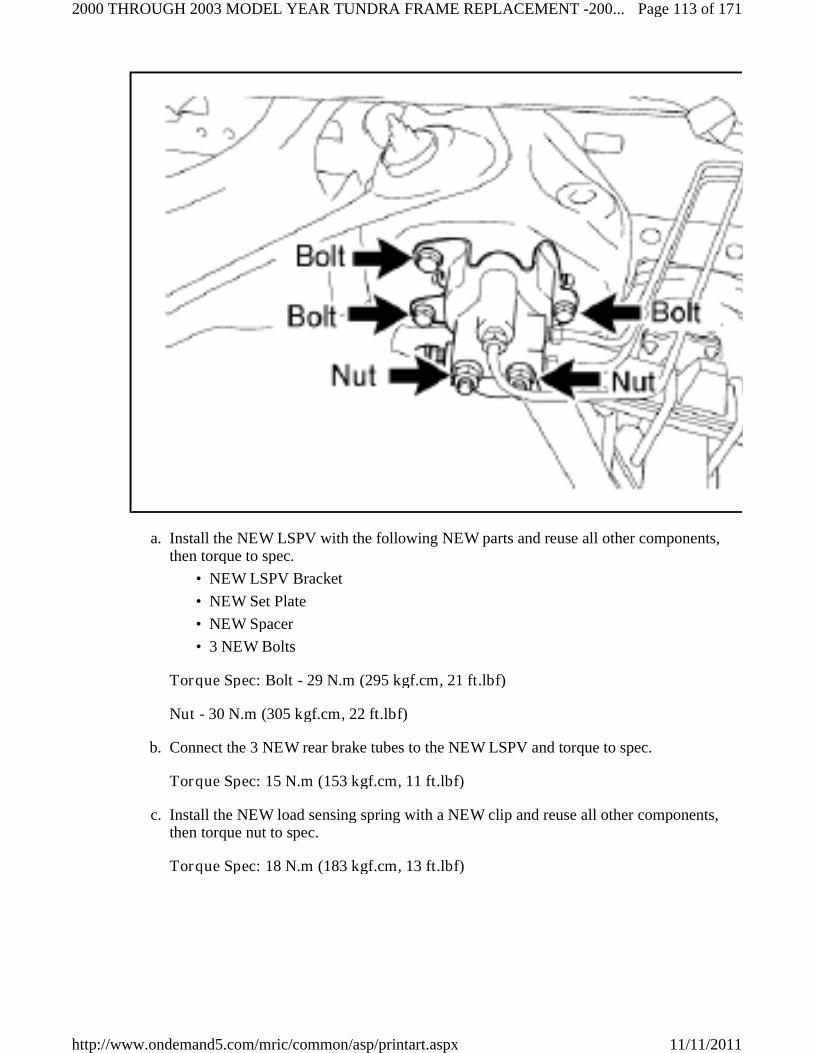
Install the NEW LSPV with the following NEW parts and reuse all other components,then torque to spec.
a.
NEW LSPV Bracket•
NEW Set Plate•
NEW Spacer•
3 NEW Bolts•
Torque Spec: Bolt - 29 N.m (295 kgf.cm, 21 ft.lbf)
Nut - 30 N.m (305 kgf.cm, 22 ft.lbf)
Connect the 3 NEW rear brake tubes to the NEW LSPV and torque to spec.b.
Torque Spec: 15 N.m (153 kgf.cm, 11 ft.lbf)
Install the NEW load sensing spring with a NEW clip and reuse all other components,then torque nut to spec.
c.
Torque Spec: 18 N.m (183 kgf.cm, 13 ft.lbf)
Page 113 of 1712000 THROUGH 2003 MODEL YEAR TUNDRA FRAME REPLACEMENT -200...
11/11/2011http://www.ondemand5.com/mric/common/asp/printart.aspx

LOAD SENSING SPRING PARTS INFORMATION
Part Number Part Name Kit # Qty
47920-34040 Spring Assy, Load Sensing 12-13 1
90467-31110 Clip (For Load Sensing Valve Boot) 12-13 1
REINSTALL THE PARKING BRAKE INTERMEDIATE LEVER (MANUALTRANSMISSION VEHICLES ONLY)
18.
REINSTALL THE NO.2 PARKING BRAKE CABLE19.
Page 114 of 1712000 THROUGH 2003 MODEL YEAR TUNDRA FRAME REPLACEMENT -200...
11/11/2011http://www.ondemand5.com/mric/common/asp/printart.aspx

Reinstall the No.2 parking brake cable with the 4 bolts, and torque to spec.a.
Torque Spec: Bolt A - 13 N.m (132 kgf.cm, 10 ft.lbf)
Bolt B - 16 N.m (163 kgf.cm, 12 ft.lbf)
Bolt C - 26 N.m (265 kgf.cm, 19 ft.lbf)
Nut - 13 N.m (132 kgf.cm, 10 ft.lbf)
Reinstall the 2 pins and 2 clips.b.
Reinstall the clip.c.
Reinstall the No. 2 parking brake cable adjustment nut and torque to spec (ManualTransmission Vehicles Only).
d.
Torque Spec: 13 N.m (132 kgf.cm, 10 ft.lbf)
REINSTALL THE FRONT DIFFERENTIAL CARRIER (4WD ONLY)20.
Page 115 of 1712000 THROUGH 2003 MODEL YEAR TUNDRA FRAME REPLACEMENT -200...
11/11/2011http://www.ondemand5.com/mric/common/asp/printart.aspx

Reinstall the front differential carrier with the 2 bolts, 4 stoppers and 3 nuts, thentorque to spec.
a.
Torque Spec: Bolt - 137 N.m (1397 kgf.cm, 101 ft.lbf)
Nut - 87 N.m (887 kgf.cm, 64 ft.lbf)
Reinstall the breather tube with the 2 clips.b.
REINSTALL THE POWER STEERING LINK ASSEMBLY W/POWER STEERINGVANE PUMP
21.
Page 116 of 1712000 THROUGH 2003 MODEL YEAR TUNDRA FRAME REPLACEMENT -200...
11/11/2011http://www.ondemand5.com/mric/common/asp/printart.aspx

Reinstall the power steering link assembly w/power steering vane pump with the boltsand nuts, then torque to spec.
a.
Torque Spec: Bolt A - 29 N.m (295 kgf.cm, 21 ft.lbf)
Bolt B - 165 N.m (1682 kgf.cm, 121 ft.lbf)
Nut A - 165 N.m (1682 kgf.cm, 121 ft.lbf)
Nut B - 130 N.m (1325 kgf.cm, 95 ft.lbf)
NOTE: When reinstalling the power steering link with thevane pump attached, have one person support thepower steering link and the other support the vanepump.
•
Make sure to keep the power steering pumpreservoir in an upright position to prevent the fluidfrom leaking out.
•
REINSTALL THE FRONT SHOCK ABSORBER22.
Page 117 of 1712000 THROUGH 2003 MODEL YEAR TUNDRA FRAME REPLACEMENT -200...
11/11/2011http://www.ondemand5.com/mric/common/asp/printart.aspx

Reinstall the front shock absorber with the bolt and 4 nuts, then torque to spec.a.
Torque Spec: Nut A - 64 N.m (652 kgf.cm, 47 ft.lbf)
Nut B - 135 N.m (1376 kgf.cm, 99 ft.lbf)
Repeat the procedure on the opposite side.b.
REINSTALL THE FRONT DRIVE SHAFT (4WD ONLY)23.
SNAP RING PARTS INFORMATION
Part Number Part Name Kit # Qty
43425-04020 Ring, Shaft Snap (For Front Drive Inner Shaft Outer) NA(1) 2
(1) Individual part(s)
Install a NEW snap ring.a.
Reinstall the front drive shaft.b.
Repeat the procedure on the opposite side.c.
Page 118 of 1712000 THROUGH 2003 MODEL YEAR TUNDRA FRAME REPLACEMENT -200...
11/11/2011http://www.ondemand5.com/mric/common/asp/printart.aspx

NOTE: Be careful not to damage the dust cover and oil seal.
REINSTALL THE FRONT SUSPENSION UPPER ARM AND STEERINGKNUCKLE ASSY
24.
Reinstall the front suspension upper arm w/steering knuckle with the bolt, nut and 2washers, then torque to spec.
a.
Torque Spec: 98 N.m (999 kgf.cm, 72 ft.lbf)
Repeat the procedure on the opposite side.b.
REINSTALL THE FOLLOWING PARTS25.
Lower Ball Joint•
LOWER BALL JOINT PARTS INFORMATION
Part Number Part Name Kit # Qty
90252-03015 Cotter Pin 1-3 2
Reinstall the lower ball joint with the nut and torque to spec.•
Torque Spec: 140 N.m (1427 kgf.cm, 103 ft.lbf)•
Page 119 of 1712000 THROUGH 2003 MODEL YEAR TUNDRA FRAME REPLACEMENT -200...
11/11/2011http://www.ondemand5.com/mric/common/asp/printart.aspx

Install the NEW cotter pin.•
Repeat the procedure on the opposite side.•
The Tie Rod End•
TIE ROD END PARTS INFORMATION
Part Number Part Name Kit # Qty
95381-03225 Cotter Pin 1-3 2
Reinstall the tie rod end with the nut and torque to spec.•
Torque Spec: 91 N.m (927 kgf.cm, 67 ft.lbf)•
Install the NEW cotter pin.•
Repeat the procedure on the opposite side.•
Front Axle Shaft Nut (4WD Only)•
Temporarily reinstall the front axle nut.•
This nut will be tightened when the vehicle is completed.•
Repeat the procedure on the opposite side.•
Front Stabilizer Bar•
FRONT STABILIZER BAR - 2000 MY PARTS INFORMATION
Part Number Part Name Kit # Qty
48824-34020 Bracket, Front Stabilizer No. 1 RH 1 1
48829-34010 Bracket, Front Stabilizer No. 1 LH 1 1
90080-11375 Bolt 4 2
90179-08256 Nut 1 2
FRONT STABILIZER BAR - 2001-2003 MY PARTS INFORMATION
Part Number Part Name Kit # Qty
48824-34030 Bracket, Front Stabilizer No. 1 RH 2-3 1
48829-34020 Bracket, Front Stabilizer No. 1 LH 2-3 1
90080-11482 Bolt 5-6 2
90182-10004 Nut 2-2 2
Reinstall the stabilizer bar with 2 NEW brackets, 2 NEW bolts and 2 NEW nuts,then torque to spec.
•
Torque Spec: 37 N.m (377 kgf.cm, 27 ft.lbf)•
Reconnect the stabilizer bar links with the 2 nuts, then torque to spec.•
Torque Spec: 69 N.m (703 kgf.cm, 50 ft.lbf)•
RECONNECT THE FRONT SPEED SENSOR CONNECTOR (ABS EQUIPPEDVEHICLES ONLY)
26.
Page 120 of 1712000 THROUGH 2003 MODEL YEAR TUNDRA FRAME REPLACEMENT -200...
11/11/2011http://www.ondemand5.com/mric/common/asp/printart.aspx

FRONT SPEED SENSOR PARTS INFORMATION
Page 121 of 1712000 THROUGH 2003 MODEL YEAR TUNDRA FRAME REPLACEMENT -200...
11/11/2011http://www.ondemand5.com/mric/common/asp/printart.aspx

Part Number Part Name Kit # Qty
82666-35200 Holder, Connector 1-3 2
89515-35030 Clamp 1-3 2
Reinstall the front speed sensor connector with 2 bolts and 2 NEW clamps, thentorque to spec.
a.
Torque Spec: 8.0 N.m (81 kgf.cm, 70 in.lbf)
Repeat the procedure on the opposite side.b.
RECONNECT THE FRONT BRAKE HOSE27.
Install a NEW bracket with a NEW bolt and torque to spec.a.
Torque Spec: 28 N.m (285 kgf.cm, 20 ft.lbf)
Reinstall the front brake hose with the clip.b.
Repeat the procedure on the opposite side.c.
INSTALL THE NEW FRONT BRAKE TUBE & NEW WAY28.
Page 122 of 1712000 THROUGH 2003 MODEL YEAR TUNDRA FRAME REPLACEMENT -200...
11/11/2011http://www.ondemand5.com/mric/common/asp/printart.aspx

FRONT BRAKE TUBE PARTS INFORMATION
Part Number Part Name Kit # Qty
47314-0C011 Tube, Front Brake, No.4 7-11 1
47317-0C011 Tube, Front Brake, No.7 7-11 1
90080-11180 Bolt - with ABS 9-11 2
90904-12066 Way, No. 2 (for front brake tube) 1-3 1
90904-12067 Way, No. 3 (for front brake tube) 1-3 1
91621-B0816 Bolt - without ABS 1-2 2
Temporarily install the NEW front brake tube and NEW way.a.
Install the NEW bolt to the NEW front way and torque to spec.b.
Torque Spec: 28 N.m (285 kgf.cm, 20 ft.lbf)
Torque the NEW front brake tube to spec.c.
Torque Spec: 15 N.m (153 kgf.cm, 11 ft.lbf)
Page 123 of 1712000 THROUGH 2003 MODEL YEAR TUNDRA FRAME REPLACEMENT -200...
11/11/2011http://www.ondemand5.com/mric/common/asp/printart.aspx

Repeat the procedure on the opposite side.d.
REINSTALL THE WHEELS29.
REINSTALL THE ENGINE AND TRANSMISSION ASSY30.
Reinstall engine and transmission assy.a.
Page 124 of 1712000 THROUGH 2003 MODEL YEAR TUNDRA FRAME REPLACEMENT -200...
11/11/2011http://www.ondemand5.com/mric/common/asp/printart.aspx

NOTE: When reinstalling the engine and transmission assy,ALWAYS use 2 engine hoists or mini cranes to lift it.
•
DO NOT use 1 engine hoist or mini crane to lift theengine and transmission assy, as the unbalancedweight may lead to an accident or injury.
•
ONLY use engine hoists or mini cranes that canproperly support the weight of the engine andtransmission assy.
•
Carefully adjust the 2 engine hoists or mini cranesused so that the engine and transmission assy isproperly balanced.
•
Attach the engine mounts with the 4 bolts and 4 NEW nuts, then torque to spec.b.
Torque Spec: 38 N.m (387 kgf.cm, 28 ft.lbf)
ENGINE MOUNTS PARTS INFORMATION
Part Number Part Name Kit # Qty
90179-10071 Nut 1-3 4
Page 125 of 1712000 THROUGH 2003 MODEL YEAR TUNDRA FRAME REPLACEMENT -200...
11/11/2011http://www.ondemand5.com/mric/common/asp/printart.aspx

Page 126 of 1712000 THROUGH 2003 MODEL YEAR TUNDRA FRAME REPLACEMENT -200...
11/11/2011http://www.ondemand5.com/mric/common/asp/printart.aspx

Attach the transmission mount with 4 NEW bolts and torque to spec.c.
Torque Spec: 18 N.m (183 kgf.cm, 13 ft.lbf)
TRANSMISSION MOUNT PARTS INFORMATION
Part Number Part Name Kit # Qty
90080-11387 Bolt 4-6 4
Page 127 of 1712000 THROUGH 2003 MODEL YEAR TUNDRA FRAME REPLACEMENT -200...
11/11/2011http://www.ondemand5.com/mric/common/asp/printart.aspx

Remove the bolt(s) and the engine hangers (5VZ-FE ONLY).d.
Reinstall the items/parts that were removed during the engine and transmission assyremoval.
e.
REINSTALL THE POWER STEERING PUMP ASSY31.
Reinstall the power steering vane pump with the 2 bolts and the nut (2UZ-FE Only) orthe bolt and the nut (5VZ-FE Only) , then toque to spec.
a.
Torque Spec: 44 N.m (450 kgf.cm, 33 ft.lbf)
Reconnect the connector (5VZ-FE Only).b.
Reinstall the drive belt.c.
RECONNECT THE FUEL TUBES AND HOSES32.
For 2UZ-FE Vehicles:
Page 128 of 1712000 THROUGH 2003 MODEL YEAR TUNDRA FRAME REPLACEMENT -200...
11/11/2011http://www.ondemand5.com/mric/common/asp/printart.aspx

2UZ-FE VEHICLES FUEL TUBES AND HOSES PARTS INFORMATION
Part Number Part Name Kit # Qty
23232-41081 Gasket (For Fuel Pump Hose) NA(1) 1
90430-12026 Gasket (For Pulsation Damper Hose) NA(1) 1
(1) Individual part(s)
Reconnect the fuel return hose with the clamp.a.
Reconnect the fuel main hose with the 2 NEW gaskets and the pulsation dumper, thentorque to spec with SST 09617-24011.
b.
Torque Spec: 39 N.m (397 kgf.cm, 29 ft.lbf)
For 5VZ-FE Vehicles:
Page 129 of 1712000 THROUGH 2003 MODEL YEAR TUNDRA FRAME REPLACEMENT -200...
11/11/2011http://www.ondemand5.com/mric/common/asp/printart.aspx

Page 130 of 1712000 THROUGH 2003 MODEL YEAR TUNDRA FRAME REPLACEMENT -200...
11/11/2011http://www.ondemand5.com/mric/common/asp/printart.aspx

5VZ-FE VEHICLES FUEL TUBES AND HOSES PARTS INFORMATION
Part Number Part Name Kit # Qty
90430-12026 Gasket (For Pulsation Damper Hose) NA(1) 2
(1) Individual part(s)
Reconnect the fuel return hose with the clamp (Illustration "A").a.
Temporarily reconnect the main fuel pipe with the union bolt and 2 NEW gaskets(Illustration "A").
b.
Reinstall the bracket bolt and torque to spec (Illustration "A").c.
Torque Spec: 8.0 N.m (81 kgf.cm, 70 in.lbf)
Torque the union bolt to spec (Illustration "A").d.
Torque Spec: 34 N.m (346 kgf.cm, 25 ft.lbf)
Reinstall the wire harness clip and bolt (Illustration "B").e.
REINSTALL THE CHARCOAL CANISTER ASSY (Only For Vehicles ProducedAfter August 2002)
33.
Page 131 of 1712000 THROUGH 2003 MODEL YEAR TUNDRA FRAME REPLACEMENT -200...
11/11/2011http://www.ondemand5.com/mric/common/asp/printart.aspx

Reinstall the charcoal canister assy with the 4 bolts and torque to spec.a.
Torque Spec: 15 N.m (153 kgf.cm, 11 ft.lbf)
Reconnect the fuel hose.b.
INSTALL THE NEW FUEL TANK STRAPS34.
Page 132 of 1712000 THROUGH 2003 MODEL YEAR TUNDRA FRAME REPLACEMENT -200...
11/11/2011http://www.ondemand5.com/mric/common/asp/printart.aspx

FUEL TANK STRAPS PARTS INFORMATION
Part Number Part Name Kit # Qty
77601-34030Fuel Tank Strap, No. 1(2) NA(1) 1
77601-34040 NA(1) 1
77603-34060Fuel Tank Strap, No. 2(2) NA(1) 1
77603-34070 NA(1) 1
(1) Individual part(s)(2) Only 1 part is used. The part number varies depending on the Kit #
Install the NEW fuel tank straps with the 2 pins and 2 clips.a.
Page 133 of 1712000 THROUGH 2003 MODEL YEAR TUNDRA FRAME REPLACEMENT -200...
11/11/2011http://www.ondemand5.com/mric/common/asp/printart.aspx

REINSTALL THE FUEL TANK35.
Fuel Tubes PARTS INFORMATION
Part Number Part Name Kit # Qty
90080-11376 Bolt - 2000-2002 MY 4-5 2
90119-A0077 Bolt - 2003 MY 6 2
Reinstall the fuel tank with the 2 NEW bolts and torque to spec.a.
Torque Spec: 62 N.m (632 kgf.cm, 46 ft.lbf)
Reinstall the fuel tubes.b.
RECONNECT THE REAR SPEED SENSOR CONNECTOR (ABS EQUIPPEDVEHICLES ONLY)
36.
Page 134 of 1712000 THROUGH 2003 MODEL YEAR TUNDRA FRAME REPLACEMENT -200...
11/11/2011http://www.ondemand5.com/mric/common/asp/printart.aspx

Reconnect the rear speed sensor connector with the nut, and torque to spec.a.
Torque Spec: 13 N.m (132 kgf.cm, 10 ft.lbf)
REINSTALL THE EXHAUST SYSTEM37.
Page 135 of 1712000 THROUGH 2003 MODEL YEAR TUNDRA FRAME REPLACEMENT -200...
11/11/2011http://www.ondemand5.com/mric/common/asp/printart.aspx

Install NEW exhaust pipe gasket(s).a.
Reinstall the exhaust with exhaust pipe supports.b.
Reinstall flange retainer with the 2 bolts and torque to spec (5VZ-FE Only).c.
Torque Spec: 48 N.m (489 kgf.cm, 35 ft.lbf)
PARTS INFORMATION (5VZ-FE)
Part Number Part Name Kit # Qty
18495-76010 Retainer, Exhaust Pipe NA(1) 1
90080-43033 Gasket, Exhaust Pipe(2) NA(1) 1
90917-06057 Gasket, Exhaust Pipe(2) NA(1) 1
(1) Individual part(s)(2) Only 1 part is used. The part number varies depending on the Kit #
Remove 2 flange retainers with 4 bolts and torque to spec (2UZ-FE Only).d.
Torque Spec: 48 N.m (489 kgf.cm, 35 ft.lbf)
Page 136 of 1712000 THROUGH 2003 MODEL YEAR TUNDRA FRAME REPLACEMENT -200...
11/11/2011http://www.ondemand5.com/mric/common/asp/printart.aspx

PARTS INFORMATION (2UZ-FE)
Part Number Part Name Kit # Qty
18495-38020 Retainer, Exhaust Pipe NA(1) 2
90080-43034 Gasket, Exhaust Pipe(2) NA(1) 2
90917-06083 Gasket, Exhaust Pipe(2) NA(1) 2
(1) Individual part(s)(2) Only 1 part is used. The part number varies depending on the Kit #
Reconnect the oxygen sensor wire harness clamp (5VZ-FE Only).e.
REINSTALL THE REAR PROPELLER SHAFT38.
Page 137 of 1712000 THROUGH 2003 MODEL YEAR TUNDRA FRAME REPLACEMENT -200...
11/11/2011http://www.ondemand5.com/mric/common/asp/printart.aspx
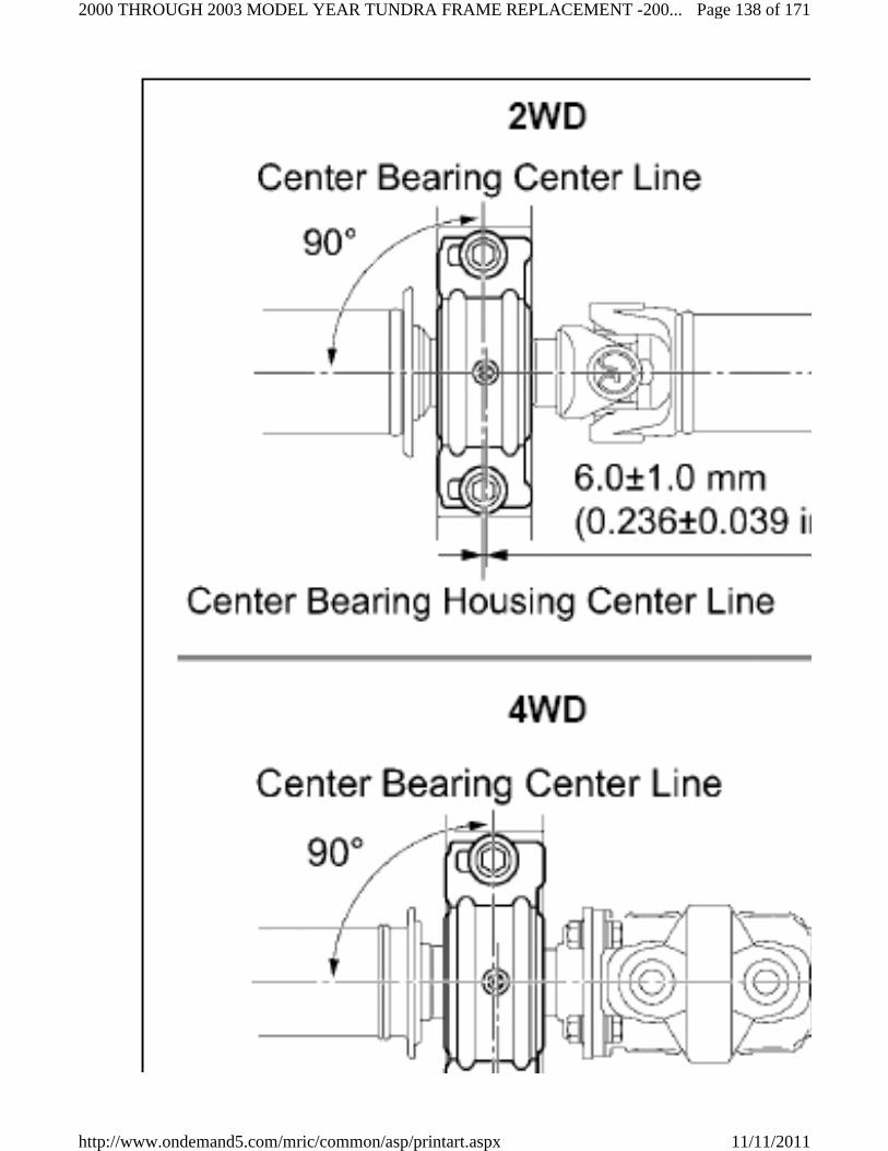
Page 138 of 1712000 THROUGH 2003 MODEL YEAR TUNDRA FRAME REPLACEMENT -200...
11/11/2011http://www.ondemand5.com/mric/common/asp/printart.aspx

Remove the SST 09325-40010 (2WD Only).a.
Referencing the matchmarks, reinstall the propeller shaft to the transmission/transfercase and torque to spec.
b.
Torque Spec: 74 N.m (750 kgf.cm, 54 ft.lbf)
Reinstall the center support bearing to the frame as shown in the illustration with 2bolts and torque to spec (3-Joint Type Only).
c.
Torque Spec: 40 N.m (408 kgf.cm, 30 ft.lbf)
Referencing the matchmarks, reinstall the propeller shaft to the rear differential with 4bolts, 4 washers and 4 nuts, then torque to spec.
d.
Torque Spec: 74 N.m (750 kgf.cm, 54 ft.lbf)
REINSTALL THE FRONT PROPELLER SHAFT39.
Referencing the matchmarks, install the front propeller shaft to the transfer case andthe front differential with 8 bolts, 8 washers and 8 nuts, then torque to spec.
a.
Torque Spec: 74 N.m (750 kgf.cm, 54 ft.lbf)
REINSTALL THE SPARE TIRE CARRIER40.
Page 139 of 1712000 THROUGH 2003 MODEL YEAR TUNDRA FRAME REPLACEMENT -200...
11/11/2011http://www.ondemand5.com/mric/common/asp/printart.aspx

SPARE TIRE CARRIER PARTS INFORMATION
Part Number Part Name Kit # Qty
90080-11180 Bolt 4-6 4
Reinstall the spare wheel carrier with the 4 NEW bolts and torque to spec.a.
Torque Spec: 20 N.m (203 kgf.cm, 14 ft.lbf)
Reinstall the spare tire.b.
REMOVE THE FRAME FROM THE LIFT41.
Remove the ratcheting tie down strap from the frame.a.
Lower the frame to the ground.b.
G. REINSTALL THE CAB BODY ASSY
INSTALL THE NEW ENGINE COMPARTMENT BRAKE TUBES1.
Without ABS
PARTS INFORMATION (WITHOUT ABS)
Page 140 of 1712000 THROUGH 2003 MODEL YEAR TUNDRA FRAME REPLACEMENT -200...
11/11/2011http://www.ondemand5.com/mric/common/asp/printart.aspx

Part Number Part Name Kit # Qty
47312-0C011 Tube, Front Brake, No. 2 7-8 1
47316-0C011 Tube, Front Brake, No. 6 7-8 1
47319-0C021 Tube, Front Brake, No. 9 7-8 1
47321-0C011 Tube, Rear Brake, No. 1 7-8 1
Install the NEW No. 2, No. 6 & No. 9 front brake tubes.a.
Install the NEW No. 1 rear brake tubes.b.
Torque all brake tubes to spec.c.
Torque Spec: 15 N.m (153 kgf.cm, 11 ft.lbf)
With ABS
PARTS INFORMATION (WITH ABS)
Part Number Part Name Kit # Qty
47313-0C011 Tube, Front Brake, No. 3 9 1
47313-0C012 Tube, Front Brake, No. 3 10-11 1
47316-0C021 Tube, Front Brake, No. 6 9 1
47316-0C022 Tube, Front Brake, No. 6 10-11 1
47319-0C021 Tube, Front Brake, No. 9 9-11 1
47322-0C011 Tube, Rear Brake, No. 2 NA(1) 1
47322-0C012 Tube, Rear Brake, No. 2 NA(1) 1
(1) Individual part(s)
Install the NEW No. 3, No. 6 & No. 9 front brake tubes.a.
Install the NEW No. 2 rear brake tubes.b.
Torque all brake tubes to spec.c.
Torque Spec: 15 N.m (153 kgf.cm, 11 ft.lbf)
Without ABS
REINSTALL THE CAB BODY ASSEMBLY2.
Page 141 of 1712000 THROUGH 2003 MODEL YEAR TUNDRA FRAME REPLACEMENT -200...
11/11/2011http://www.ondemand5.com/mric/common/asp/printart.aspx
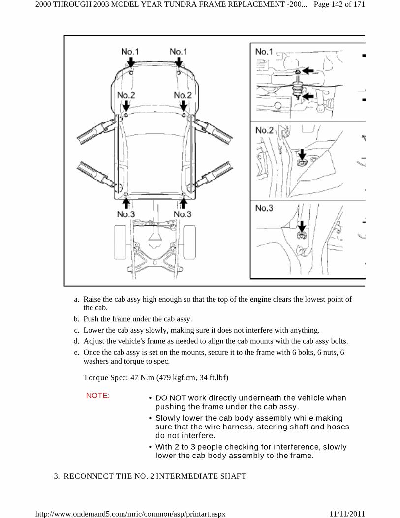
Raise the cab assy high enough so that the top of the engine clears the lowest point ofthe cab.
a.
Push the frame under the cab assy.b.
Lower the cab assy slowly, making sure it does not interfere with anything.c.
Adjust the vehicle's frame as needed to align the cab mounts with the cab assy bolts.d.
Once the cab assy is set on the mounts, secure it to the frame with 6 bolts, 6 nuts, 6washers and torque to spec.
e.
Torque Spec: 47 N.m (479 kgf.cm, 34 ft.lbf)
NOTE: DO NOT work directly underneath the vehicle whenpushing the frame under the cab assy.
•
Slowly lower the cab body assembly while makingsure that the wire harness, steering shaft and hosesdo not interfere.
•
With 2 to 3 people checking for interference, slowlylower the cab body assembly to the frame.
•
RECONNECT THE NO. 2 INTERMEDIATE SHAFT3.
Page 142 of 1712000 THROUGH 2003 MODEL YEAR TUNDRA FRAME REPLACEMENT -200...
11/11/2011http://www.ondemand5.com/mric/common/asp/printart.aspx

PARTS INFORMATION
Part Number Part Name Kit # Qty
90080-11555 Bolt 4-6 2
NOTE: Use precaution when performing this step, as you will need towork underneath the vehicle.
Make sure the front wheels are in a straight-ahead position and the steering wheel iscentered.
a.
Referencing the matchmarks, connect the No. 2 intermediate shaft to the control valveshaft with the NEW bolt "B".
b.
Remove bolt "A" and install the NEW bolt "A".c.
Torque all bolts to spec.d.
Torque Spec: 35 N.m (356 kgf.cm, 26 ft.lbf)
Disconnect the seat belt that is holding the steering wheel.e.
RECONNECT THE FRONT SPEED SENSOR CONNECTORS (ABS EQUIPPEDVEHICLES ONLY)
4.
Page 143 of 1712000 THROUGH 2003 MODEL YEAR TUNDRA FRAME REPLACEMENT -200...
11/11/2011http://www.ondemand5.com/mric/common/asp/printart.aspx

Page 144 of 1712000 THROUGH 2003 MODEL YEAR TUNDRA FRAME REPLACEMENT -200...
11/11/2011http://www.ondemand5.com/mric/common/asp/printart.aspx

Reconnect the harness clamp and front speed sensor connector.a.
Repeat the procedure on the opposite side.b.
RECONNECT THE FRONT BRAKE TUBES5.
Page 145 of 1712000 THROUGH 2003 MODEL YEAR TUNDRA FRAME REPLACEMENT -200...
11/11/2011http://www.ondemand5.com/mric/common/asp/printart.aspx

Page 146 of 1712000 THROUGH 2003 MODEL YEAR TUNDRA FRAME REPLACEMENT -200...
11/11/2011http://www.ondemand5.com/mric/common/asp/printart.aspx

Reconnect the front brake tube and torque to spec.a.
Torque Spec: 15 N.m (153 kgf.cm, 11 ft.lbf)
Repeat the procedure on the opposite side.b.
REINSTALL THE FRONT FENDER APRON SEAL6.
Page 147 of 1712000 THROUGH 2003 MODEL YEAR TUNDRA FRAME REPLACEMENT -200...
11/11/2011http://www.ondemand5.com/mric/common/asp/printart.aspx

Page 148 of 1712000 THROUGH 2003 MODEL YEAR TUNDRA FRAME REPLACEMENT -200...
11/11/2011http://www.ondemand5.com/mric/common/asp/printart.aspx

Reinstall the 4 front fender apron seals with the 21 clips.a.
REINSTALL THE FOLLOWING PARTS7.
Transfer Case Shift Lever (5VZ-FE 4WD Only)•
Manual Transmission Shift Lever (Manual Transmission Vehicles Only)•
RECONNECT THE OXYGEN SENSOR WIRE HARNESS CONNECTOR (5VZ-FEONLY)
8.
Insert the oxygen sensor wire harness into the cab assy.a.
Reinstall the oxygen sensor wire harness grommet to the cab assy.b.
Reconnect the oxygen sensor wire harness connector.c.
Reinstall the right front cowl side trim panel.d.
Reinstall the right access cab door scuff plate (Access Cab Only).e.
Reinstall the right front door scuff plate.f.
RECONNECT THE FRAME WIRE HARNESS CONNECTOR9.
Page 149 of 1712000 THROUGH 2003 MODEL YEAR TUNDRA FRAME REPLACEMENT -200...
11/11/2011http://www.ondemand5.com/mric/common/asp/printart.aspx

Insert the frame wire harness into the cab assy.a.
Reinstall the frame wire harness grommet to the cab assy.b.
Reconnect the frame wire harness connector(s).c.
Reinstall the left front cowl side trim panel.d.
Reinstall the left access cab door scuff plate (Access Cab Only).e.
Reinstall the left front door scuff plate.f.
NOTE: The number of connectors will differ depending on thevehicle spec.
RECONNECT THE ENGINE WIRE HARNESS10.
Page 150 of 1712000 THROUGH 2003 MODEL YEAR TUNDRA FRAME REPLACEMENT -200...
11/11/2011http://www.ondemand5.com/mric/common/asp/printart.aspx
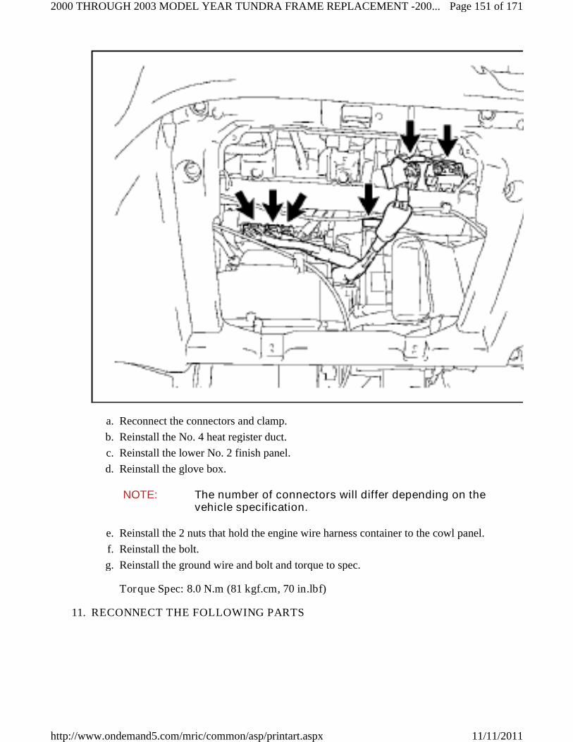
Reconnect the connectors and clamp.a.
Reinstall the No. 4 heat register duct.b.
Reinstall the lower No. 2 finish panel.c.
Reinstall the glove box.d.
NOTE: The number of connectors will differ depending on thevehicle specification.
Reinstall the 2 nuts that hold the engine wire harness container to the cowl panel.e.
Reinstall the bolt.f.
Reinstall the ground wire and bolt and torque to spec.g.
Torque Spec: 8.0 N.m (81 kgf.cm, 70 in.lbf)
RECONNECT THE FOLLOWING PARTS11.
Page 151 of 1712000 THROUGH 2003 MODEL YEAR TUNDRA FRAME REPLACEMENT -200...
11/11/2011http://www.ondemand5.com/mric/common/asp/printart.aspx

PARTS INFORMATION (A/C)
Part Number Part Name Kit # Qty
90099-14120 O-Ring 1-3 1
90099-14121 O-Ring 1-3
1
Air Conditioning Discharge and Suction Hoses.•
Install a NEW o-ring to the A/C discharge and suction hoses.•
Reconnect the A/C discharge and suction hoses and torque to spec.•
Torque Spec: 10 N.m (100 kgf.cm, 7 ft.lbf)•
Water/Heater Hoses (Engine Side)•
RECONNECT THE VANE PUMP OIL RESERVOIR (2UZ-FE ONLY)12.
Reinstall the vane pump oil reservoir with the 2 nuts and torque spec.a.
Page 152 of 1712000 THROUGH 2003 MODEL YEAR TUNDRA FRAME REPLACEMENT -200...
11/11/2011http://www.ondemand5.com/mric/common/asp/printart.aspx

Torque Spec: 8.0 N.m (81 kgf.cm, 70 in.lbf)
RECONNECT THE NO.1 FUEL HOSE (ONLY FOR VEHICLES PRODUCED ONOR BEFORE AUGUST 2002)
13.
DISCONNECT THE NO.2 ENGINE WIRE HARNESS14.
Page 153 of 1712000 THROUGH 2003 MODEL YEAR TUNDRA FRAME REPLACEMENT -200...
11/11/2011http://www.ondemand5.com/mric/common/asp/printart.aspx

Reinstall the clip and reconnect the No.2 engine wire harness.a.
Reconnect the (+) positive battery cable with the 2 nuts and torque to spec.b.
Torque Spec: Nut A - 10 N.m (102 kgf.cm, 7 ft.lbf)
Nut B - 13 N.m (132 kgf.cm, 10 ft.lbf)
Reconnect the ground wire with the bolt and torque to spec.c.
Torque Specification: 8.0 N.m (81 kgf.cm, 70 in.lbf)
Reconnect the clamp and connector.d.
Reinstall the relay block cover.e.
RECONNECT THE HOSES15.
Page 154 of 1712000 THROUGH 2003 MODEL YEAR TUNDRA FRAME REPLACEMENT -200...
11/11/2011http://www.ondemand5.com/mric/common/asp/printart.aspx

Page 155 of 1712000 THROUGH 2003 MODEL YEAR TUNDRA FRAME REPLACEMENT -200...
11/11/2011http://www.ondemand5.com/mric/common/asp/printart.aspx

Reconnect the A.D.D. vacuum hose (5VZ-FE 4WD Only).a.
Reconnect the vacuum hose (5VZ-FE Only).b.
Reconnect the EVAP hose(s).c.
Reconnect the brake booster hose.d.
NOTE: The number of hoses will differ depending on the vehiclespecification.
RECONNECT THE FOLLOWING PARTS16.
Cruise Control Cable (If Equipped)•
Accelerator Cable, Engine Side (Only For Vehicles Produced On Or Before August2002)
•
REINSTALL THE FOLLOWING PARTS17.
Air Cleaner Case Assy & Hose•
Throttle Body Cover (2UZ-FE Only)•
REINSTALL THE OIL COOLER PIPE (2UZ-FE ONLY)18.
Page 156 of 1712000 THROUGH 2003 MODEL YEAR TUNDRA FRAME REPLACEMENT -200...
11/11/2011http://www.ondemand5.com/mric/common/asp/printart.aspx

Reinstall the oil cooler pipe with the bolt and torque to spec.a.
Torque Spec: 12 N.m (122 kgf.cm, 9 ft.lbf)
Reconnect the hose.b.
REINSTALL THE FOLLOWING PARTS19.
Radiator•
PARTS INFORMATION (RADIATOR)
Part Number Part Name Kit # Qty
16492-21050 O-Ring (2UZ-FE Only) NA(1) 1
96711-19007 O-Ring (5VZ-FE Only) NA(1) 1
(1) Individual part(s)
Install a NEW o-ring to the A/C discharge and suction hoses.•
Reconnect the A/C discharge and suction hoses and torque to spec.•
Torque Spec: 10 N.m (100 kgf.cm, 7 ft.lbf)•
Page 157 of 1712000 THROUGH 2003 MODEL YEAR TUNDRA FRAME REPLACEMENT -200...
11/11/2011http://www.ondemand5.com/mric/common/asp/printart.aspx

Front Bumper Assy - Steel Bumper Only•
Reinstall with the NEW side mounting brackets, bolts and nuts, then torque tospec.
•
Torque Spec:•
Bolt - 58 N.m (591 kgf.cm, 42 ft.lbf)
Nut - 12 N.m (122 kgf.cm, 9 ft.lbf)
PARTS INFORMATION (FRONT BUMPER)
Part Number Part Name Kit # Qty
52145-0C010 Bracket, Front Bumper Side Mounting, RH 4-6 1
52146-0C010 Bracket, Front Bumper Side Mounting, LH 4-6 1
90119-A0049 Bolt 4-6 4
90179-06314 Nut 1-2 2
90179-08063 Nut 1-2 2
Front Bumper Assy - Resin Bumper Only•
Reinstall with the bolts and torque to spec.•
Torque Spec: 7.0 N.m (71 kgf.cm, 62 in.lbf)•
RECONNECT THE CLUTCH MASTER CYLINDER TUBE (MANUALTRANSMISSION VEHICLES ONLY)
20.
Page 158 of 1712000 THROUGH 2003 MODEL YEAR TUNDRA FRAME REPLACEMENT -200...
11/11/2011http://www.ondemand5.com/mric/common/asp/printart.aspx

Reconnect the clutch hose to the bracket with the clip.a.
Reconnect the clutch master cylinder tube and torque to spec.b.
Torque Spec: 15 N.m (153 kgf.cm, 11 ft.lbf)
RECONNECT THE REAR BRAKE TUBES21.
Page 159 of 1712000 THROUGH 2003 MODEL YEAR TUNDRA FRAME REPLACEMENT -200...
11/11/2011http://www.ondemand5.com/mric/common/asp/printart.aspx

Reconnect the 2 rear brake tubes and torque to spec.a.
Torque Spec: 15 N.m (153 kgf.cm, 11 ft.lbf)
RECONNECT THE NO.1 FUEL HOSE22.
Page 160 of 1712000 THROUGH 2003 MODEL YEAR TUNDRA FRAME REPLACEMENT -200...
11/11/2011http://www.ondemand5.com/mric/common/asp/printart.aspx

Reconnect the No.1 fuel hose with the clipa.
RECONNECT THE NO. 1 PARKING BRAKE CABLE23.
Page 161 of 1712000 THROUGH 2003 MODEL YEAR TUNDRA FRAME REPLACEMENT -200...
11/11/2011http://www.ondemand5.com/mric/common/asp/printart.aspx

Page 162 of 1712000 THROUGH 2003 MODEL YEAR TUNDRA FRAME REPLACEMENT -200...
11/11/2011http://www.ondemand5.com/mric/common/asp/printart.aspx

For Automatic Transmission Vehicles
Reinstall the No.1 parking brake cable assy and tighten the nut.a.
Reinstall the clip.b.
For Manual Transmission Vehicles
Reinstall the No.1 parking brake cable assy with the clip.a.
Reinstall the lever pivot pin and clip.b.
RECONNECT THE SHIFT CABLE24.
Page 163 of 1712000 THROUGH 2003 MODEL YEAR TUNDRA FRAME REPLACEMENT -200...
11/11/2011http://www.ondemand5.com/mric/common/asp/printart.aspx

Page 164 of 1712000 THROUGH 2003 MODEL YEAR TUNDRA FRAME REPLACEMENT -200...
11/11/2011http://www.ondemand5.com/mric/common/asp/printart.aspx

Reconnect the shift cable with the bolt(s) and torque to spec.a.
Torque Spec: 2UZ-FE - 18 N.m (183 kgf.cm, 13 ft.lbf)
5VZ-FE - 71 N.m (724 kgf.cm, 52 ft.lbf)
Reinstall the washer and pin.b.
H. REINSTALL THE BED ASSY
REINSTALL THE BED ASSY1.
Using a "TORX" socket wrench (T55), reinstall the bed assy "TORX" bolts and torqueto spec.
a.
Torque Spec: 86 N.m (877 kgf.cm, 63 ft.lbf)
NOTE: Ask 4 to 6 people to help with the reinstallation of thebed assy to the frame.
•
Evenly support the bed assy when reinstalling it.•
Page 165 of 1712000 THROUGH 2003 MODEL YEAR TUNDRA FRAME REPLACEMENT -200...
11/11/2011http://www.ondemand5.com/mric/common/asp/printart.aspx

Be careful not to damage or hit the fuel inlet pipewhen reinstalling the bed assy.
•
REINSTALL THE FUEL INLET PIPE2.
Reinstall the fuel inlet pipe with the 2 nuts and torque to spec.a.
Torque Spec: 27 N.m (275 kgf.cm, 20 ft.lbf)
REINSTALL THE FRAME WIRE HARNESS3.
Page 166 of 1712000 THROUGH 2003 MODEL YEAR TUNDRA FRAME REPLACEMENT -200...
11/11/2011http://www.ondemand5.com/mric/common/asp/printart.aspx

Reconnect the 4 wire harness clamps to the bed assy.a.
Reconnect the connectors.b.
NOTE: The number of connectors will differ depending onthe vehicle spec.
•
Use new clamps if the original ones are damaged.•
REINSTALL THE FOLLOWING PARTS4.
Fuel Tank Filler Pipe Shielda.
Side Step Assy (If Equipped)b.
Rear Mudguards (If Equipped)c.
Trailer Hitch (If Equipped)d.
Rear Bumper Assye.
PARTS INFORMATION (REAR BUMPER)
Part Number Part Name Kit # Qty
90119-12311 Bolt 1-3 4
90119-A0073 Bolt 4-6 6
Reinstall with 10 NEW bolts and torque to spec.•
For Vehicles Produced On Or Before August 2002•
Page 167 of 1712000 THROUGH 2003 MODEL YEAR TUNDRA FRAME REPLACEMENT -200...
11/11/2011http://www.ondemand5.com/mric/common/asp/printart.aspx

Torque Spec: 80 N.m (815 kgf.cm, 59 ft.lbf)
For Vehicles Produced After August 2002•
Torque Spec: 100 N.m (1019 kgf.cm, 73 ft.lbf)
Center Rear Bumper Padf.
License Plate Lightsg.
I. FINAL ASSEMBLY
*5. REINSTALL THE BATTERY
*6. REFILL THE FOLLOWING FLUIDS
Brake Fluid•
Remove the brake tubes from the master cylinder.•
Refill with Toyota Dot 3 Brake Fluid.•
Bleed the master cylinder.•
Reinstall the brake tubes to the master cylinder and torque to spec.•
Torque Spec: 15 N.m (153 kgf.cm, 11 ft.lbf)•
Refill with Toyota Dot 3 Brake Fluid.•
Bleed the brake system at each wheel and torque the bleeder screws to spec.•
Torque Spec: 11 N.m (112 kgf.cm, 8 ft.lbf)•
Clutch Fluid (Manual Transmission Vehicles Only)•
Refill with Toyota Dot 3 Brake Fluid.•
Bleed the clutch system and torque the bleeder screws to spec.•
Torque Spec: 11 N.m (112 kgf.cm, 8 ft.lbf)•
Coolant•
Refill with Toyota Long Life Coolant.•
Bleed the cooling system.•
Front Differential•
PARTS INFORMATION (FRONT DIFFERENTIAL)
Part Number Part Name Kit # Qty
12157-10010 Gasket, Front Differential Filler Plug NA(1) 1
90430-24003 Gasket, Front Differential Drain Plug NA(1) 1
(1) Individual part(s)
Install a NEW drain plug washer and torque to spec.•
Torque Spec: 65 N.m (662 kgf.cm, 48 ft.lbf)•
Refill with Hypoid Gear Oil API GL-5 75W-90.•
Install a NEW filler plug washer and torque to spec.•
Torque Spec: 39 N.m (397 kgf.cm, 29 ft.lbf)•
*7. START THE VEHICLE AND INSPECT THE FOLLOWING FOR LEAKS
Page 168 of 1712000 THROUGH 2003 MODEL YEAR TUNDRA FRAME REPLACEMENT -200...
11/11/2011http://www.ondemand5.com/mric/common/asp/printart.aspx

Fuel System•
Start the engine and let it run for 5 seconds, then stop the engine and inspect forleaks.
•
If there are no leaks, restart the engine and re-inspect.•
Cooling System•
Brake System•
Clutch System (Manual Transmission Vehicles Only)•
Front Differential System•
*8. RECHARGE THE A/C SYSTEM AND CHECK FOR PROPER OPERATIONAND REFRIGERANT LEAKS
*9. CHECK THE OPERATION OF THE FOLLOWING SYSTEMS AND ADJUSTAS NEEDED
IMPORTANT: STOP
Make sure to follow the procedure outlined in the appropriaterepair manual for the vehicle you are working on whenchecking, and if needed, adjusting the operation of thesystems listed below. This is an important step, and must beperformed thoroughly to ensure proper operation of thesesystems.
Parking Brake Travel•
Shift Control Lever (Automatic Transmission Vehicles Only)•
Clutch Pedal (Manual Transmission Vehicles Only)•
LSPV (LSPV Equipped Vehicles Only)•
*10. CHECK ALL FLUID LEVELS AND ADJUST AS NEEDED
*11. TORQUE THE FRONT AXLE NUT (4WD ONLY)
Page 169 of 1712000 THROUGH 2003 MODEL YEAR TUNDRA FRAME REPLACEMENT -200...
11/11/2011http://www.ondemand5.com/mric/common/asp/printart.aspx

PARTS INFORMATION
Part Number Part Name Kit # Qty
95381-04045 Cotter Pin NA(1) 2
(1) Individual part(s)
Remove the front wheels.a.
Torque the front axle nut to spec.b.
Torque Spec: 235 N.m (2396 kgf.cm, 173 ft.lb)
Reinstall the lock cap with the NEW cotter pin.c.
Reinstall the grease cap.d.
Page 170 of 1712000 THROUGH 2003 MODEL YEAR TUNDRA FRAME REPLACEMENT -200...
11/11/2011http://www.ondemand5.com/mric/common/asp/printart.aspx

Repeat the procedure on the opposite side.e.
Reinstall the front wheels and torque to spec.f.
Torque Spec: 110 N.m (1121 kgf.cm, 81 ft.lbf)
NOTE: If the holes for the cotter pin are not aligned, tighten theaxle nut further, up to 60°.
*12. PERFORM A WHEEL ALIGNMENT
*13. CHECK THE HEADLIGHT AIM AND ADJUST AS NEEDED
*14. REINSTALL THE ENGINE UNDER COVER
Reinstall the engine under cover with NEW bolts and NEW screws and torque to spec.a.
Torque Spec: 29 N.m (295 kgf.cm, 21 ft.lbf)
PARTS INFORMATION
Part Number Part Name Kit # Qty
90080-11373 Bolt 4-6 9
90159-60440 Screw 1-3 4
*15. CHECK FOR DTC'S AND REPAIR AS NEEDED
*16. PERFORM INITIALIZATION
*17. FINAL INSPECTION
Check the operation of the following systems:a.
4WD System (4WD Only)•
Interior Lights•
Exterior Lights•
HVAC System•
Audio System•
Power Windows•
Power Door Locks•
All Gauges, Indicators and Warning Lights•
Cooling Fans•
Etc.•
*18. TEST DRIVE THE VEHICLE
J. APPENDIX
As required by Federal Regulations, please make sure all recalled parts (original parts) removedfrom the vehicle are disposed of in a manner in which they will not be reused. Adequate time hasbeen provided in the repair time to cut up and dispose of the perforated frame.
© 2008 Mitchell Repair Information Co., LLC.
Page 171 of 1712000 THROUGH 2003 MODEL YEAR TUNDRA FRAME REPLACEMENT -200...
11/11/2011http://www.ondemand5.com/mric/common/asp/printart.aspx