ARTEMIS - DigitalCommons@USU
29
Building Canada’s Future In Space ARTEMIS: Low-Cost Ground Station Antenna Arrays for Microspacecraft Mission Support G. James Wells Mark A. Sdao Robert E. Zee Space Flight Laboratory University of Toronto Institute for Aerospace Studies 11 August 2004
Transcript of ARTEMIS - DigitalCommons@USU

Building Canada’s Future In Space
ARTEMIS:Low-Cost Ground Station
Antenna Arrays for Microspacecraft Mission Support
G. James Wells Mark A. Sdao Robert E. Zee
Space Flight LaboratoryUniversity of Toronto Institute for Aerospace Studies
11 August 2004

Building Canada’s Future In Space
Overview• Low S/N due to extreme range or high data rate and
low spacecraft power. E.g. microspacecraft.
• Deep space communications – JPL antenna arraying
• Low cost antenna arrays – issues and solutions
• ARTEMIS: software & hardware prototyping
• Experiments and scenario analysis – microspace & JPL missions
• Conclusions: applications of ARTEMIS to low cost arrays and DSN augmentation

Building Canada’s Future In Space
Deep Space Communications
70m Antenna Goldstone, CA, USA
70m, 34m Antennas Canberra, Australia
Mars Global Surveyor Galileo
Low-gain antennaArraying needed
Nominally 34 m dish antenna only
Deep Space Network• Overbooked• Time is expensive

Building Canada’s Future In Space
Communication Link Disparity
GalileoMars Global
SurveyorMicrosatellite-
class RadioFrequency (MHz) 2290 8400 2232
Spacecraft Transmit Power (mW) 15000 10000 5000
Spacecaft Antenna Gain (dBi) 7 42 0
EIRP (dBm) 47.8 82.0 36.0
70m Goldstone 3m Antenna 6.1m AntennaFrequency (MHz) 2290 2232 2232
Ground Station G/T (dB/K) 59.02 10.71 16.80
Spacecraft Transmitter Comparison
Microsat• omni antennas• lower powerGround
Station Receiver
ComparisonMicrosat Ground Station• Low sensitivity

Building Canada’s Future In Space
Ground Station Arrays as a Solution
• Effective improvement without incurring dramatic price increaseswhile allowing for large aperture areas - costs scale linearly for increasing effective aperture
• Combine signals at baseband• Very Long Baseline Interferometry (several JPL correlation
techniques available) - sharing same oscillator mitigates frequency errors, but is inflexible
34
134
234
334
434
534
634
734
834
934
0 2 4 6 8 10 12
SNR Improvement (dB)Es
timat
ed G
roun
d St
atio
n C
ost
($kC
DN) Single Ground
StationArray GroundStation
Estimated Cost Comparison
between Array & Single Dish Ground
Station

Building Canada’s Future In Space
JPL Array Signal Combination Techniques
RF → IF →Baseband
RF → IF →Baseband
Carrier Demodulation
SubcarrierDemodulation (if required)
Symbol Synch
Carrier Demodulation
SubcarrierDemodulation (if required)
Symbol Synch
ΣTelemetry
Symbol Determination
RF → IF →Baseband
RF → IF →Baseband
Delay & Phase Shift
Delay & Phase Shift
Cross-Correlator Σ Telemetry
Demodulation
Symbol Stream Combining (SSC)
Full Spectrum Combining (FSC)
Time DomainCorrelation Only

Building Canada’s Future In Space
Ground Station Arrays as a Solution
• VLBI array must be capable of compensating for errors such as :
Phase offsets due to each antenna receiving the signal at a different time due to their different geographic locations (Atomic clocks, GPS to solve this)Phase offsets introduced when downconverting the signal from RF to basebandFrequency and phase offsets between the various local oscillators of each antenna in the array and the spacecraft(DSN uses hydrogen masers to give high accuracy)
• Array decorrelation will occur unless these errors can be detected and corrected

Building Canada’s Future In Space
Frequency Correlation: OFDM Signal
• Frequency Division Multiplexing:
• Orthogonal Frequency Division Multiplexing:
Multiple LowData Rate Channelsfor easier correlation
More channels enablesfrequency domain correlation which allows use of less accurate oscillators.
Orthogonality ensures spectral efficiency

Building Canada’s Future In Space
Low-Cost Alternative: ARTEMIS• ARraying Techniques for Enhanced Multiplexing of Interferometric Signals• JPL arraying techniques: Full Spectrum Combining• Orthogonal Frequency Division Multiplexing (OFDM)• Use both Frequency Domain and Time Domain Correlation.• Time domain correlation easier due to multiple low data rate carriers.• Can use sloppier equipment or improve correlation capabilities.
Low-Cost Ground
Equipment+
JPL Arraying Techniques (VLBI, Correlation)
Digital Signal Processing (OFDM)
+
RF → IF →Baseband
RF → IF →Baseband
Delay & Phase Shift
Delay & Phase Shift
Cross-Correlator Σ Telemetry
Demodulation

Building Canada’s Future In Space
ARTEMIS Microspace ScenariosScenario
Microsatellite (LEO)
Microspacecraft (Moon)
Microspacecraft (Mars Scenario 1)
Microspacecraft (Mars Scenario 2)
Frequency (MHz) 2232 2232 2232 2232Spacecraft Transmit
Power (mW) 400 4000 4000 4000Spacecaft Antenna
Gain (dBi) 0 0 0 0EIRP (dBm) 26.0 36.0 36.0 36.0
Path Loss (dBm) -172.9 -212.2 -265.0 -265.0Diameter of Antennas
in Ground Array (m) 3 3 6.1 6.1Individual Ground Station G/T (dB/K) 10.3 10.7 16.8 16.8
Data Rate (bps) 4000000 14400 1 15Individual Receiver
Eb/No (dB) -4.1 -8.5 -13.6 -25.4
• ARTEMIS provides both frequency and time domain correlation and allows for use of low-cost commercial-grade equipment (commercially available oscillators) in a ground station array.
• Better correlation gets arraying gain closer to theoretical combining gain limit (determined by aperture area).

Building Canada’s Future In Space
ARTEMIS Experimental Hardware & Software Development
Spacecraft OFDM Signal
Generation
Digital-to-Analog (DAC)
Interface
Analog-to-Digital (ADC)
Interface
Ground Correlation, Correction & Combination
Spacecraft Transmitter DSP
Ground Station Central Site DSP
Input Data
Array Output
Correlation & BER Logs
Noise and Array Offsets
(Frequency, Time)
IF Wired Link
(digital upconversion to IF of up to 38.4
kHz)
• All modules developed in software and running on TI floating-point DSPs (optimized for I/FFT function)
• In future: implement wireless RF link between transmitter and receiver

Building Canada’s Future In Space
Results Applied to ARTEMIS MicrospaceScenarios
ScenarioMicrosatellite
(LEO)Microspacecraft
(Moon)Microspacecraft
(Mars Scenario 1)Microspacecraft
(Mars Scenario 2)Diameter of Antennas in
Ground Array (m) 3 3 6.1 6.1Data Rate (bps) 4000000 14400 1 15
Individual Receiver Eb/No (dB) -4.1 -8.5 -13.6 -25.4
Required Number of OFDM Channels for
Frequency Correlation 128 / 16 512 / 32 2048 / 128 >4096 / 2048Min. Array Size to
Achieve 2 dB Eb/No 4 12 38 500Equivalent Single Antenna Size (m) 6 10 38 136
• Results of scenarios extrapolated using hardware experimental results; they also validated the original software simulations done in Matlab
• 2 dB combined signal Eb/No will give a bit error rate of 10-5 for a BPSK modulated OFDM signal assuming Reed-Solomon & convolutional forward error correction is used

Building Canada’s Future In Space
ARTEMIS DSN Scenario
• ARTEMIS can augment or replace DSN antennas with arrays of smallantennas or facilitate the arraying of large antennas to improve ground station performance
Scenario
Mars Global Surveyor
(DSN)
Mars Global Surveyor
(small station)Frequency (MHz) 8400 8400
Spacecraft Transmit Power (mW) 10000 10000
Spacecaft Antenna Gain (dBi) 42 42
EIRP (dBm) 82 82Path Loss (dBm) -276.56 -276.56
Diameter of Antennas on Ground (m) 34 6.1
Individual Ground Station G/T (dB/K) 51.77 25.56
Data Rate (bps) 42667 42667Individual Receiver
Eb/No (dB) 9.51 -16.70
Scenario
Mars Global Surveyor
(small station)Diameter of Antennas in
Ground Array (m) 6.1Individual Receiver
Eb/No (dB) -16.70Required Number of OFDM Channels for
Frequency Correlation >4096 / 256Min. Array Size to
Achieve 2 dB Eb/No 62

Building Canada’s Future In Space
Current Hardware Experiment
• Concurrent Time & Frequency CorrelationJPL FSC, used by the DSN to correct time offsets, would fail if any significant frequency offset were to occur between the oscillators The structure of the OFDM signals makes it possible for ARTEMIS to perform both time & frequency correlation even if both types of offsets are present

Building Canada’s Future In Space
Future Hardware Experiments
• Addition of an RF link to current experimental apparatus
• LEO flight experiment on a future SFL mission
OFDM transceiver in orbit (S-Band)ARTEMIS array (including central correlatorsite) on ground

Building Canada’s Future In Space
Conclusion• Deep Space Communications:
ARTEMIS as a low-cost alternative to DSN
• For new ground stations, can use low-cost RF equipment (e.g. inexpensive oscillators, 100-1000 times less stable)
• Can create ad-hoc array with existing antenna infrastructure (large or small) using low-cost equipment.
• Microspace Applications of ARTEMIS
• High data rate LEO missions
• Greater range: Interplanetary Microsats
• Concept Study Completed.
• Hardware & Software Prototyping in Progress and Nearing Completion
• LEO flight experiment on future SFL mission

Building Canada’s Future In Space
Natural Resources

Building Canada’s Future In Space
What Does ARTEMIS Offer?
• ARTEMIS offers a low-cost alternative to the DSN for spacecraft communications
Enables higher data rate microsatellite LEO missions
Enables interplanetary microspacecraft missions
• ARTEMIS can also provide accurate ranging & tracking of interplanetary spacecraft
• Retrofit existing assets or develop low-cost new assets

Building Canada’s Future In Space
Frequency Correlation: OFDM Signal
4-Channel OFDM Symbol Viewed in the Time Domain
Orthogonal: kth channel has k cycles
Inverse Fast Fourier Transform (IFFT) used
to create OFDM Symbol
Σ
Time length of each OFDM symbol is 4 times the bit time
Each channel contains 1 bit of info

Building Canada’s Future In Space
Frequency Correlation Techniques Tested
1) Correlate, between individual receivers, every OFDM symbol
2) Correlate, between each receiver and the central site DSP, an OFDM symbol with a known structure (ie. training symbol) periodically inserted into the data transmission

Building Canada’s Future In Space
Hardware Experiment Results
• 1st Frequency Correlation Method
-500
0
500
1000
1500
2000
-25-20-15-10-5051015
Individual Receiver Signal Eb/No (dB)Fr
eque
ncy
Cor
rela
tion
Erro
r (H
z)
Single Channel Signal8-Channel OFDM16-Channel OFDM32-Channel OFDM64-Channel OFDM128-Channel OFDM256-Channel OFDM512-Channel OFDM

Building Canada’s Future In Space
Hardware Experiment Results
• 2nd Frequency Correlation Method
-500
0
500
1000
1500
2000
-25-20-15-10-5051015
Individual Receiver Signal Eb/No (dB)Fr
eque
ncy
Cor
rela
tion
Erro
r (H
z)
Single Channel Signal8-Channel OFDM16-Channel OFDM32-Channel OFDM64-Channel OFDM128-Channel OFDM256-Channel OFDM512-Channel OFDM

Building Canada’s Future In Space
Frequency Correlation: OFDM Signal
Modulation Symbol
Generation (eg. BPSK)
-1…,+1,-1,-1D symbol/sec.
X
Carrier Oscillator
Freq. = F
Upconvertto RF
TransmitY bits/sec.1…,0,1,1
XX
X
X
Σ
IFFT
Modulation Symbol
Generation (eg. BPSK)
110
1
Y bits/sec.1,…0,1,1
Y/N bits/sec.
Serial-to-Parallel N-Channels
-1-1+1
-1
D/N symbol/sec.
Upconvertto RF
Transmit
Carrier Oscillator
Freq. = D/N
Carrier Oscillator
Freq. = 2D/N
Carrier Oscillator
Freq. = 3D/N
Carrier Oscillator
Freq. = D
Building Canada’s Future In Space
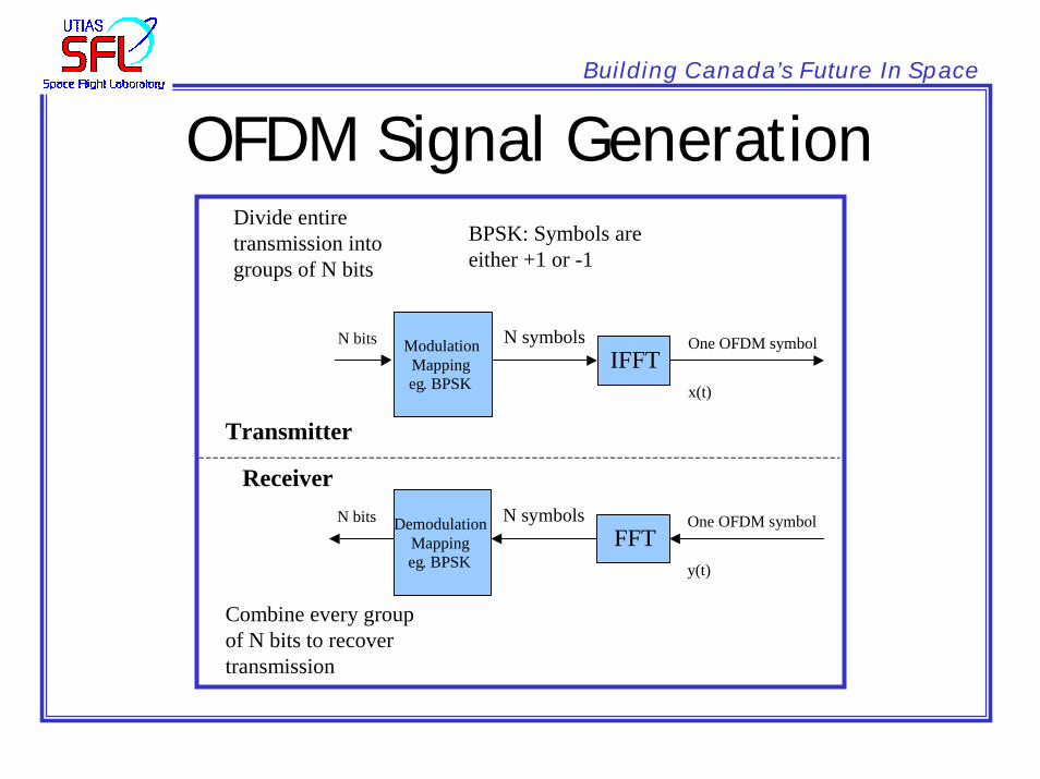
OFDM Signal Generation
Modulation Mapping eg. BPSK
N bits IFFT
Transmitter
Receiver
x(t)
One OFDM symbolN symbols
Demodulation Mapping eg. BPSK
N bits FFT
y(t)
One OFDM symbolN symbols
Divide entire transmission into groups of N bits
Combine every group of N bits to recover transmission
BPSK: Symbols are either +1 or -1

Building Canada’s Future In Space
ARTEMIS Ground Station Block Diagram
Antenna 1
Antenna 2
Antenna na
Remote Sites
Central Site
a1(t)
a2(t)
ana(t)
Geo. Time Correction
&
Doppler Correction
a1(t)
a2(t)
ana’(t)
Correlator
Frequency then Time
Offset Corrections Applied to
SignalsCorrection 2
Correction na
Σ Output
Perform BPSK Demodulation
Summation of Corrected Signals
A(t)FFT
OFDM Dechannelization
A(f)

Building Canada’s Future In Space
Frequency Correlation Block Diagram
a1(f)
am(f)
FFT Multiplication IFFT
Frequency-Domain Cross-
Correlation Function
c1m(υ)
Find υmax such that c1m(υmax) is a
maximum
υmax is the frequency offset correction for
the mth antenna
FFT
a1(t)
am(t)
Frequency correction
for mth
antenna
Cross-Correlation Algorithm

Building Canada’s Future In Space
Time Correlation Block Diagram
a1(f)
am(f)
Multiplication IFFT
Find τ max such that c1m(τ max) is a
maximum
τ max is the time offset correction for the mth
antenna
Time-Domain Cross-
Correlation Function
c1m(τ)FFT
a1(t)
am(t)
Shift am(f) by υmax
(frequency offset)
Time correction
for mth
antenna

Building Canada’s Future In Space
OFDM BER Curve

Building Canada’s Future In Space
OFDM BER Curve With FEC