
Art%20 e sierra%20etp%20mantenimiento
15
Notes: MANTENIMIENTO is the most important Spanish technical journal about Maintenance. This journal is published by AEM AsociaciÛn EspaÒola de Mantenimiento (Spanish Manitenance Asociation) which belong spanish utilities like IBERDROLA or UNION FENOSA , heavy industries like REPSOL or CEMENTOS MOLINS and important repair workshops like Talleres PETIT (SARELEM).
-
Upload
pan-american-silver-corporation -
Category
Business
-
view
64 -
download
0
Transcript of Art%20 e sierra%20etp%20mantenimiento

Notes: MANTENIMIENTO is the most important Spanish technical journal about Maintenance.
This journal is published by AEM AsociaciÛn EspaÒola de Mantenimiento (Spanish
Manitenance Asociation) which belong spanish utilities like IBERDROLA or UNION FENOSA ,
heavy industries like REPSOL or CEMENTOS MOLINS and important repair workshops like
Talleres PETIT (SARELEM).
Condition Based Maintenance in
Transformers
ETP METHOD Emilio Sierra Gómez
Iberdrola Generación, S.A.
The normal operation of transformers can be afected by several external factors.
Diagnostic’s systems are based on periodical tests performace which have the aim to
determine when and where is going to appear alterations that afect in abnormal way
to some of transformer components.
This Condition Based Maintenance will allow us to detect incipient transformer
problems before of breakdown occur, allowing us:
• To avoid urgent performances.
• To avoid high costs of repair and transport.
• To avoid unavailabilities of long duration.
• Optimization of hours – men.
Diagnostic and evaluation systems could be:
• Electrical
• Physical-Chemical.
Mantenimiento Julio-Agosto 2001
The transformer diagnostic system developed by Unitronics and IBERDROLA, ETP
SYSTEM, performes the necessary tests to detect and to confirm any problem in
each part of the transformer, it means that the ETP determines the current status of
each part of the tranformer:
• Solid and liquid insulation.
• Windings.
• Tap changer.
• Magnetic core.
Transformer status knowledge will allow us to programme the most suitable actions:
• To continue in service.
• To limit functions.
• Specific reviews.
• To repair or to substitute
2.-ETP TRANSFORMER EVALUATION SYSTEM.
This system can be applicated to all kind of transformer or autotransformer, single-
phase or three phase, power or distribution transformer, independently of the power
of nominal voltage.
The ETP filosophy is based in basic principles of Condition Based Maintenance:
• Non destructive tests. • Reliable and repetitive. • Results are automaticaly stored and facility of managing.
THE SYSTEM ETP is formed by four units of measurement (UM). Each part of the
transformer will be characterized by the measurements of two units.

• Winding: UM-1,UM-3
• Tap changer: UM-1,UM-3
• Magnetic package: UM-1,UM-5
• Insulation: UM-2, tan d
ETP SYSTEM developed by Iberdrola/Unitronics is based in an adquisition system
controled by PC via RS232:
With the ETP System could be detected and confirmed the following problems:
TAP CHANGER
• Faults in the Tap changer. • High resistance connections.
WINDINGS
• SHORTCIRCUIT between turns • Winding cuts. • Check the winding connections, CONNECTION GROUP • Connection’s Slackening. • Open windings. • Hot spots in the windings. INSULATION
• Problems in oil- papper insulation, DEGRADATION. • Absolute value of the insulation, LEAKAGE CURRENT.

MAGNETIC CORE • Defects in magnetic core • Windings displacements
UNITRONICS ETP SYSTEM.
UM1B
This measurement unit performs a three-phase Transformer Turn Ratio test,
connection group checking and core problems testing based on exciting currents
measurement.
The test is made with AC and it automatically measures each winding in relation with
the other ones. Throught UM1B test results, we can detect following problems:
• Short circuit between turns.
• Winding cuts.
• Tap changer problems.
• Defects in magnetic core.
• Check winding connections, CONNECTION GROUP
UM2 This unit performs the following measurements in an automatic and guided way:
• Recovery Voltage and Time Constant that allows us to predict an anomalous
ageing in paper/oil insulation.
• Insulation Resistance and Polarization Index, that give us an overview of
insulation condition.
For the calculation of those parameters, this unit applies different D.C. voltage levels
between windings and ground. This test is totally non-destructive for the machine
and allows us to detect problems in the transformer like:
• Degradation of solid dielectric
• Degradation of liquid dielectric
• Contamination of the insulation
This is the only one test that could detect the paper insulation status
independiently of oil and therefore it could give information about the machine
remanent life.
UM3 This unit performs low resistance measurements specially of the windings of any kind
of transformers or autotransformer, providing both simple and compound resistance
value for high and low voltage and tertiary. The results are provided at reference
temperature specified by the operator.
The UM3B unit permits to do the following measurements automatically:
• Automatic winding resistance on the three phases.
• Resistance values corrected in temperature.
• Calculations of individual and compound resistance values (∆ or Y).

The measurement technique used is the metric ratio resistance method (measured
on four wires) and automatic magnetization/desmagnetization of the core, which
avoid breaks of the equipment of measurement, guarantees the safety of the
operator and the precision and repetitivity of the measurement
This test is totally non-destructive for the machine and allows us to detect problems
in the transformer like:
• SHORTCIRCUIT between turns
• Winding cuts.
• Connection’s Slackening.
• Open windings.
• Hot spots in the windings
• Tap changer defects
UM5 UM5B measures the short circuit impedance of power , distribution transformers and
autotransformers applying a voltage test to the high voltage winding of the
transformer and measuring the voltage excitation, the current excitation and phase
angle deviation between them: V1 and I1. It’s carried out with the transformer LV
winding in short circuit.
With the short circuit impedance measurement it is possible to detect problems in
the transformer like:
• Displacements between windings
• Open winding
• Short-circuiting between turns
9
4.-Conclusiones.
This transformer evaluation method and the test system has been developed like a
combination of 40 years of IBERDROLA test experience, testing Power and
Distribution Transformer (more than 20.000 field test), and the system development
of UNITRONICS during the last 10 years.
ETP method performs the necessary non destructive tests in order to make a
complete transformer status analysis.
ETP System performs this method in a very easy and guided way. Some of tis
advantages are:
• Reduced measurement time (2 – 4 hours, report generation included). • Unification of the measurement systems. • Instrumentation Cost reduction. • Portable. • Simplification of calculations • Common data base to all tests • Correction of results. • Numerical and Graphical results presentation. • Immediate reports production • It facilitates the trend analysis
ETP allows to establish a Predictive Maintenance Program of Tranformer without the
need of high cost and complicated instruments. Also, it is not necesary large
transformer outage, becouse ETP system make a complete dignostic of the
transformer status in 3 hours.
10
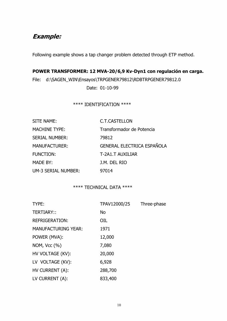
Example:
Following example shows a tap changer problem detected through ETP method.
POWER TRANSFORMER: 12 MVA-20/6,9 Kv-Dyn1 con regulación en carga.
File: d:\SAGEN_WIN\Ensayos\TRPGENER79812\RDBTRPGENER79812.0
Date: 01-10-99
**** IDENTIFICATION ****
SITE NAME: C.T.CASTELLON
MACHINE TYPE: Transformador de Potencia
SERIAL NUMBER: 79812
MANUFACTURER: GENERAL ELECTRICA ESPAÑOLA
FUNCTION: T-2A1.T AUXILIAR
MADE BY: J.M. DEL RIO
UM-3 SERIAL NUMBER: 97014
**** TECHNICAL DATA ****
TYPE: TPAV12000/25 Three-phase
TERTIARY:: No
REFRIGERATION: OIL
MANUFACTURING YEAR: 1971
POWER (MVA): 12,000
NOM, Vcc (%) 7,080
HV VOLTAGE (KV): 20,000
LV VOLTAGE (KV): 6,928
HV CURRENT (A): 288,700
LV CURRENT (A): 833,400
11
CONNECTION GROUP: Dyn1
** TAP CHANGERSELECTOR OF THE HV **
HANDLING NUMBER: 28158
REGULATION: Load
SWITCH TYPE: MA/2
MANUFACTURER: G.E.E.
TAPS NUMBER: 22
NOMINAL TAP: 11
CENTRAL TAPS NUMBER: 1
STEP (V): 200
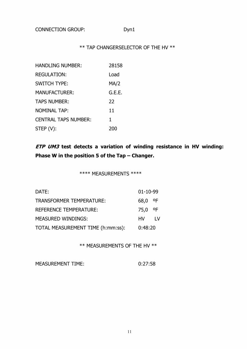
ETP UM3 test detects a variation of winding resistance in HV winding:
Phase W in the position 5 of the Tap – Changer.
**** MEASUREMENTS ****
DATE: 01-10-99
TRANSFORMER TEMPERATURE: 68,0 ºF
REFERENCE TEMPERATURE: 75,0 ºF
MEASURED WINDINGS: HV LV
TOTAL MEASUREMENT TIME (h:mm:ss): 0:48:20
** MEASUREMENTS OF THE HV **
MEASUREMENT TIME: 0:27:58
12
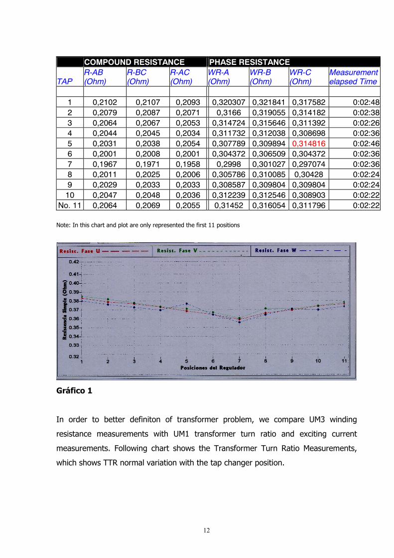
COMPOUND RESISTANCE PHASE RESISTANCE
TAP R-AB (Ohm)
R-BC (Ohm)
R-AC (Ohm)
WR-A (Ohm)
WR-B (Ohm)
WR-C (Ohm)
Measurement elapsed Time
1 0,2102 0,2107 0,2093 0,320307 0,321841 0,317582 0:02:482 0,2079 0,2087 0,2071 0,3166 0,319055 0,314182 0:02:383 0,2064 0,2067 0,2053 0,314724 0,315646 0,311392 0:02:264 0,2044 0,2045 0,2034 0,311732 0,312038 0,308698 0:02:365 0,2031 0,2038 0,2054 0,307789 0,309894 0,314816 0:02:466 0,2001 0,2008 0,2001 0,304372 0,306509 0,304372 0:02:367 0,1967 0,1971 0,1958 0,2998 0,301027 0,297074 0:02:368 0,2011 0,2025 0,2006 0,305786 0,310085 0,30428 0:02:249 0,2029 0,2033 0,2033 0,308587 0,309804 0,309804 0:02:24
10 0,2047 0,2048 0,2036 0,312239 0,312546 0,308903 0:02:22No. 11 0,2064 0,2069 0,2055 0,31452 0,316054 0,311796 0:02:22
Note: In this chart and plot are only represented the first 11 positions
Gráfico 1
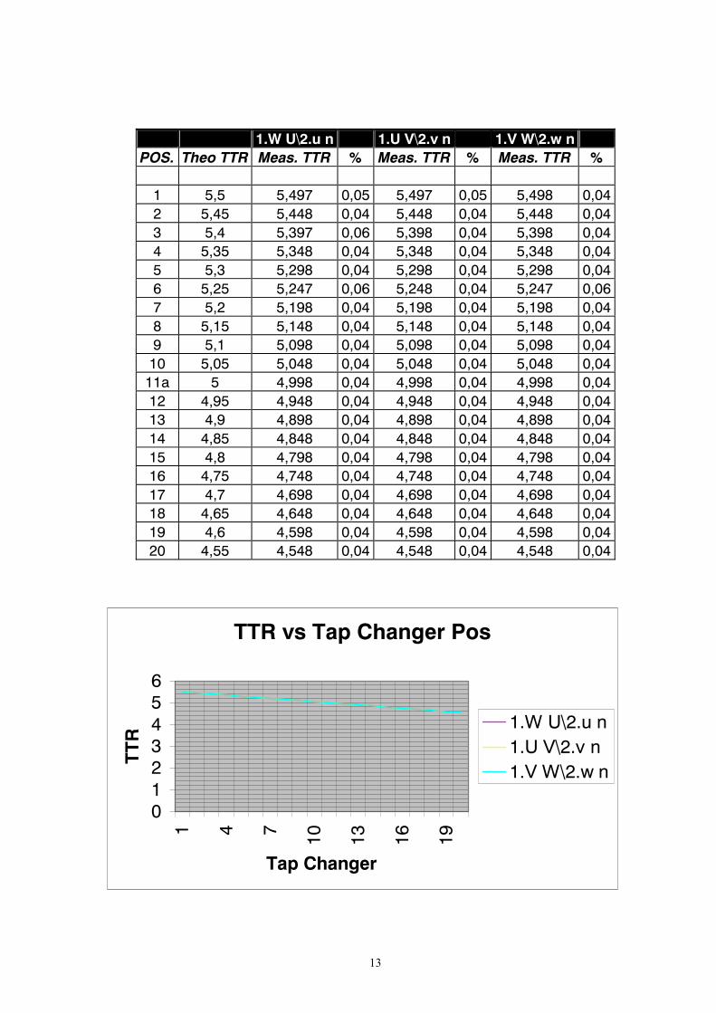
In order to better definiton of transformer problem, we compare UM3 winding
resistance measurements with UM1 transformer turn ratio and exciting current
measurements. Following chart shows the Transformer Turn Ratio Measurements,
which shows TTR normal variation with the tap changer position.
13
1.W U\2.u n 1.U V\2.v n 1.V W\2.w n POS. Theo TTR Meas. TTR % Meas. TTR % Meas. TTR %
1 5,5 5,497 0,05 5,497 0,05 5,498 0,04 2 5,45 5,448 0,04 5,448 0,04 5,448 0,04 3 5,4 5,397 0,06 5,398 0,04 5,398 0,04 4 5,35 5,348 0,04 5,348 0,04 5,348 0,04 5 5,3 5,298 0,04 5,298 0,04 5,298 0,04 6 5,25 5,247 0,06 5,248 0,04 5,247 0,06 7 5,2 5,198 0,04 5,198 0,04 5,198 0,04 8 5,15 5,148 0,04 5,148 0,04 5,148 0,04 9 5,1 5,098 0,04 5,098 0,04 5,098 0,04
10 5,05 5,048 0,04 5,048 0,04 5,048 0,04 11a 5 4,998 0,04 4,998 0,04 4,998 0,04 12 4,95 4,948 0,04 4,948 0,04 4,948 0,04 13 4,9 4,898 0,04 4,898 0,04 4,898 0,04 14 4,85 4,848 0,04 4,848 0,04 4,848 0,04 15 4,8 4,798 0,04 4,798 0,04 4,798 0,04 16 4,75 4,748 0,04 4,748 0,04 4,748 0,04 17 4,7 4,698 0,04 4,698 0,04 4,698 0,04 18 4,65 4,648 0,04 4,648 0,04 4,648 0,04 19 4,6 4,598 0,04 4,598 0,04 4,598 0,04 20 4,55 4,548 0,04 4,548 0,04 4,548 0,04
TTR vs Tap Changer Pos
0123456
1 4 7 10 13 16 19
Tap Changer
TT
R
1.W U\2.u n1.U V\2.v n1.V W\2.w n
14
EXCITING CURRENT TEST (110 V Test):
NOMINAL POSITION
1.W U\2.u n 1.U V\2.v n 1.V W\2.w n
Exciting Current (A) 0,0064 0,0062 0,0064
Conclusions:
Winding resistance readings shows that Phase W, HV winding, tap changer position 5
has anormalous increasing of its resitance value.
Transformer turn ratio is normal in all tap changer position.
Exciting current readings are very similar in the three phases.
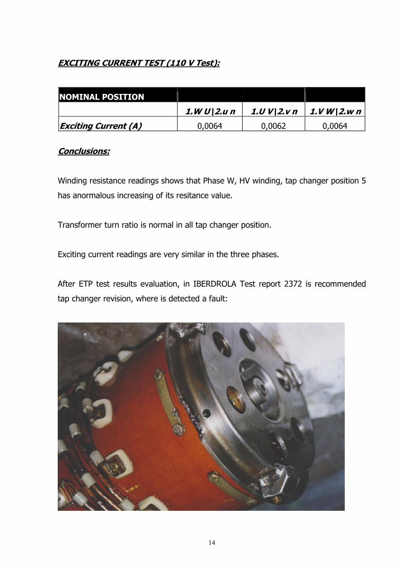
After ETP test results evaluation, in IBERDROLA Test report 2372 is recommended
tap changer revision, where is detected a fault:

15
After tap-changer repair, it was mounted and a ETP test was made again. Following
Winding Resistance readings show that the problem has desappeared and now the
variations between taps are as expected.
Gráfico 2