ART. 403-AP ART. 403-AP-M - microelettronica … · distanze operative / operational approach and...
2
Cooper CSA Srl Corsico (MI) Italy N.Verde: 800-449433 www.coopercsa.it @Copyright Cooper CSA 2012 ART. 403-AP Contatto magnetico in metallo di ridotte dimensioni, colore alluminio / Compact metal magnetic contact, silver color ART. 403-AP-M Contatto magnetico in metallo di ridotte dimensioni, colore marrone / Compact metal magnetic contact, brown color SPECIFICHE GENERALI GENERAL SPECIFICATIONS INSTALLAZIONE CONFORME ALLA NORMA INSTALLATION AS PER STANDARD Materiale contenitore Housing material Lega metallica Metal alloy Funzionamento Operation NC con i due componenti vicini NC when the two components are near Temp. di funzionamento Operating temperature -25°C ÷ +50°C Grado di protezione IP degree Certificato IPx2 (dichiarato IP65 da Cooper CSA) Certified IPx2 (declared IP65 by Cooper CSA) V max 42,4 Vpeak - 60Vdc I max 1 A W max 10 W Identificazione Identification Numero seriale/lotto su ogni componente Serial number/batch on each component EN50131-2-6 GR 2 CL III CSA08911-G OK OK La certificazione decade per installazioni diverse da quelle rappresentate nelle figure. Certification is void if the devices are installed differently. I contatti magnetici sono componenti passivi, le grandezze elettriche indicate sono le massime applicabili Magnetic contacts are passive components, max applicable voltage and current are displayed in table
Transcript of ART. 403-AP ART. 403-AP-M - microelettronica … · distanze operative / operational approach and...

Cooper CSA Srl Corsico (MI) Italy N.Verde: 800-449433 www.coopercsa.it
@C
opyright C
ooper C
SA
2012
ART. 403-AP Contatto magnetico in metallo di ridotte dimensioni, colore alluminio / Compact metal magnetic contact, silver color
ART. 403-AP-M Contatto magnetico in metallo di ridotte dimensioni, colore marrone / Compact metal magnetic contact, brown color
SPECIFICHE GENERALIGENERAL SPECIFICATIONS
INSTALLAZIONE CONFORME ALLA NORMAINSTALLATION AS PER STANDARD
Materiale contenitoreHousing material
Lega metallicaMetal alloy
FunzionamentoOperation
NC con i due componenti viciniNC when the two components are near
Temp. di funzionamentoOperating temperature
-25°C ÷ +50°C
Grado di protezioneIP degree
Certificato IPx2 (dichiarato IP65 da Cooper CSA)Certified IPx2 (declared IP65 by Cooper CSA)
V max 42,4 Vpeak - 60VdcI max 1 AW max 10 WIdentificazioneIdentification
Numero seriale/lotto su ogni componenteSerial number/batch on each component
EN50131-2-6 GR 2 CL III
CS
A08911-G
OKOK
La certificazione decade per installazioni diverse da quelle rappresentate nelle figure.Certification is void if the devices are installed differently.
I contatti magnetici sono componenti passivi, le grandezze elettriche indicate sono le massime applicabiliMagnetic contacts are passive components, max applicable voltage and current are displayed in table
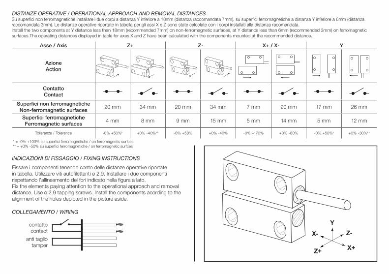
DISTANZE OPERATIVE / OPERATIONAL APPROACH AND REMOVAL DISTANCES
INDICAZIONI DI FISSAGGIO / FIXING INSTRUCTIONS
Asse / Axis Z+ Z- X+ / X- Y
AzioneAction
ContattoContact
Superfici non ferromagneticheNon-ferromagnetic surfaces
20 mm 34 mm 20 mm 34 mm 7 mm 20 mm 17 mm 26 mm
Superfici ferromagneticheFerromagnetic surfaces
4 mm 8 mm 9 mm 15 mm 5 mm 14 mm 5 mm 12 mm
Tolleranze / Tolerance -0% +50%* +0% -40%** -0% +50% +0% -40% -0% +170% +0% -60% -0% +50%* +0% -30%**
Fissare i componenti tenendo conto delle distanze operative riportate in tabella. Utilizzare viti autofilettanti ø 2,9. Installare i due componenti rispettando l’allineamento dei fori indicato nella figura a lato.Fix the elements paying attention to the operational approach and removal distance. Use ø 2.9 tapping screws. Install the components acording to the alignment of the holes depicted in the picture aside.
Y
X+
Z-
Z+
X-
COLLEGAMENTO / WIRING
contattocontact
anti tagliotamper
Su superfici non ferromagnetiche installare i due corpi a distanza Y inferiore a 18mm (distanza raccomandata 7mm), su superfici ferromagnetiche a distanza Y inferiore a 6mm (distanza raccomandata 3mm). Le distanze operative riportate in tabella per gli assi X e Z sono state calcolate con i corpi installati alla distanza racomandata.Install the two components at Y distance less than 18mm (recommended 7mm) on non-ferromagnetic surfaces, at Y distance less than 6mm (recommended 3mm) on ferromagnetic surfaces.The operating distances displayed in table for axes X and Z have been calculated with the components mounted at the recommended distance.
* = -0% +100% su superfici ferromagnetiche / on ferromagnetic surfces** = +0% -50% su superfici ferromagnetiche / on ferromagnetic surfces