
Michael bowen oil and gas | Oil and Gas investments providing
Upload
truongkietCategory
view
214download
1
sUPPLeMenTARy RePORT TO THe eis
3PROjecT descRiPTiOn
Back to contents
enter here
Arrow Bowen Gas Project SREIS
Section 3 Project Description
Prepared for Arrow Energy Pty Ltd 3-1 42627140
3 Project Description
3.1 Overview A conceptual description of the Bowen Gas Project (the Project) was prepared to inform the EIS. The project description formed the basis for which all initial baseline environmental studies were undertaken and guided the approach for how impact assessment studies were conducted for the EIS.
Since publication of the EIS for public comment in Q1 2013, Arrow’s field development plan and conceptual design for the Project has advanced. This progression is the result of ongoing exploration activities that have improved Arrow’s understanding of the gas resource, and the evolution of Arrow’s planning and operational processes. Refinements to the basis of design, including revised typical arrangements, configurations, construction methods and CSG infrastructure design are being undertaken by Arrow to prepare for the front-end engineering design (FEED) phase and incorporate new design elements to improve efficiencies and reduce the Project’s disturbance footprint.
Table 3-1 below presents the changes that have occurred to the project description subsequent to publishing the EIS. Where the changes to Project elements are described in more detail within this chapter a cross reference to the relevant section is provided in the table.

Arrow Bowen Gas Project SREIS
Section 3 Project Description
Prepared for Arrow Energy Pty Ltd 3-2 42627140
Table 3-1 Project Changes Since Release of the EIS
EIS Section EIS Project Description Description of Change (in Supplement)
4.3 – Major Infrastructure Components Integrated processing facility (IPF) – to treat (dehydrate) and compress the gas to export pressure, and treat water for beneficial use.
The term IPF is no longer being used and is now incorporated into central gas processing facilities (CGPF). Water treatment facilities (WTFs) will be co-located at CGPFs. Simply a change to naming convention.
4.3.1 – Production Facilities Figure 4-4 Indicative Facilities Layout
For the purpose of the EIS, production facility locations were assumed to be located somewhere near the centre of each development area (17 in total) of 12 km radius. The indicative layout of production facilities across the Project area were presented in Figure 4–4 of the EIS.
Due to expected low gas pressures, as a result of the preliminary engineering undertaken in the concept select phase, the number of development (or drainage) areas has increased to 33 in total, however; each of these drainage areas now represent an approximate 6 km radius catchment area for gathering well production (gas and water), and distributing to surface production facilities located at or near the centre of drainage area. These 33 drainage areas will be developed over the Project life, however; Arrow does not expect all facilities to be operating together at one single time. See Figure 3–1. The number and location of development areas has been revised – this influences the indicative location of facilities. This change is now presented in Figure 3–1.
4.3.1.1 – Facility Gas Compression Table 4-2 Production Facility Compression Types
Detailed information in Table 3-2 outlines a comparison between compression types presented in the EIS and the new case for the SREIS.
See Table 3–2 for a comparison between compression types presented in the EIS and the new case for the SREIS.
4.3.1.1 – Range of Facility Sizes Table 4-3 Production Facility Area Requirements
Production facility area requirements: • FCF = 200 x 250 m; • CGPF = 600 x 250 m; and • IPF = 800 x 250 m + up to 1 km2 for dams.
Production facility area requirements: • FCF = 200 x 380 m (maximum size); and • CGPF = 500 x 250 m + up to 0.6 km2 for dams
(dimensions are provisional, may vary following design review).

Arrow Bowen Gas Project SREIS
Section 3 Project Description
Prepared for Arrow Energy Pty Ltd 3-3 42627140
EIS Section EIS Project Description Description of Change (in Supplement)
4.3.1.2 –Field Compression Facilities Field compression facilities (FCF) were to be installed to boost the gas pressure to enable transportation of the gas over long distances.
FCFs will be installed to boost the gas pressure and enable transportation of the gas over long distances. FCFs will also now include a water transfer station (WTS) to facilitate transfer of water from FCF to FCF en route to a CGPF.
4.3.1.2 – Field Compression Facilities Previously electrical power was to be reticulated to an FCF from the nearest CGPF or IPF.
It is presently anticipated that electrical power will be reticulated to FCFs from a central location, which will be the CGPFs for Phase 1 of the development, and strategic FCFs for subsequent phases. An FCF will receive high voltage power via Arrow owned 66 kV distribution network from where the voltage is stepped-down to 11 kV for distribution to users within the facility and to wellhead facilities. See Section 3.6.
4.3.1.2 – Field Compression Facilities At an FCF, water was to be received from the local production area gathering systems, collected in a storage tank, and pumped to the closest IPF.
At an FCF, water will be received from the local production area gathering systems, collected in storage tanks, and pumped to another FCF or to a CGPF, whichever is the closest.
4.3.1.3 – Central Gas Processing Facilities Gas was to be compressed to reach a high pressure (10,200 to 15,000 kPag).
The gas will be compressed to reach high pressure (10,200 to 13,500 kPag) - see Table 3–2.
4.3.1.3 – Central Gas Processing Facilities A combination of screw and reciprocating compression was assumed as the reference case for the EIS.
Centrifugal compressors are proposed to be used as part of the SREIS case - see Table 3–2.
4.3.1.3 – Central Gas Processing Facilities Gas flows at the Project’s CGPFs were likely to range between 60 and 210 TJ/d.
Peak installed capacity at the CGPFs is likely to be between 360 TJ/d to 450 TJ/d - see Table 3–2.
4.3.1.3 – Central Gas Processing Facilities The gas was to be received at the facility at a controlled pressure of approximately 40 kPag at the inlet manifold and 30 kPag at the suction to compression.
The gas will be received at the CGPF from the FCFs at a controlled pressure of approximately 3,100 kPag at the inlet manifold and 3,000 kPag at the suction to compression.

Arrow Bowen Gas Project SREIS
Section 3 Project Description
Prepared for Arrow Energy Pty Ltd 3-4 42627140
EIS Section EIS Project Description Description of Change (in Supplement)
4.3.1.3 – Central Gas Processing Facilities A slug catcher will separate any bulk water in the gas before it is directed to the first stage of compression.
Any bulk water in the gas is separated in a slug catcher before the gas is directed to the first stage of compression. Water collected at the slug catcher will be collected in the utility dam to avoid contaminating the WTF with the corrosion inhibitor. See Section 3.4.
4.3.1.3 – Central Gas Processing Facilities At a CGPF, water was to be received from the local production area gathering systems, or from gathering systems of adjacent production areas via low pressure trunklines. The water was to be collected either in a utility dam or tank and pumped, via a WTS to an IPF.
At the co-located WTF, produced water will be collected, treated and then stored onsite for distribution to the end user, which may include irrigation, mine wash water, water utility company or town water supply. Further details are provided in Section 3.4
4.3.1.4 – Integrated Processing Facilities Integrated processing facilities (IPF). The term ‘IPF’ is no longer being used for the SREIS case. WTFs will now be co-located with the CGPFs not at the previously named IPFs. See Section 3.4.
4.3.2 – Production Well Development Up to 6,625 production wells were expected to be drilled throughout the Project area over the approximate 40 year Project life to maintain gas supply to the LNG plant.
Approximately 4,000 production wells will be drilled throughout the Project area over life of the Project (up to 40 years) to maintain gas feed to the LNG plant.
4.3.2 – Production Well Development Figure 4-6 Indicative SIS Well Schematic
Surface-in-seam (SIS) chevron wells in a dual lateral configuration were proposed to be used on a nominal 800 m grid pattern. Multi-seam hydraulically fractured: vertical, cased and cemented wells, which are perforated and fracture-stimulated to provide formation access. It was proposed that up to 25% of wells developed could potentially be hydraulically fractured. The indicative layout of the SIS chevron well was presented in Figure 4-6.
Currently, development plans involve drilling and completion of two base case well types: • Multi Branch Laterals (MBLs): multi branched horizontal
wells drilled in-seam to intersect a vertical producer; and • Multi-seam hydraulically fractured: vertical, cased and
cemented wells, which are perforated and fracture-stimulated to provide formation access. As with the EIS, it is proposed that up to 25% of wells developed could potentially be hydraulically fractured.
See Section 3.3, Figures 3-2 to 3-4 show the layout of the MBL wells.
Arrow Bowen Gas Project SREIS
Section 3 Project Description
Prepared for Arrow Energy Pty Ltd 3-5 42627140
EIS Section EIS Project Description Description of Change (in Supplement)
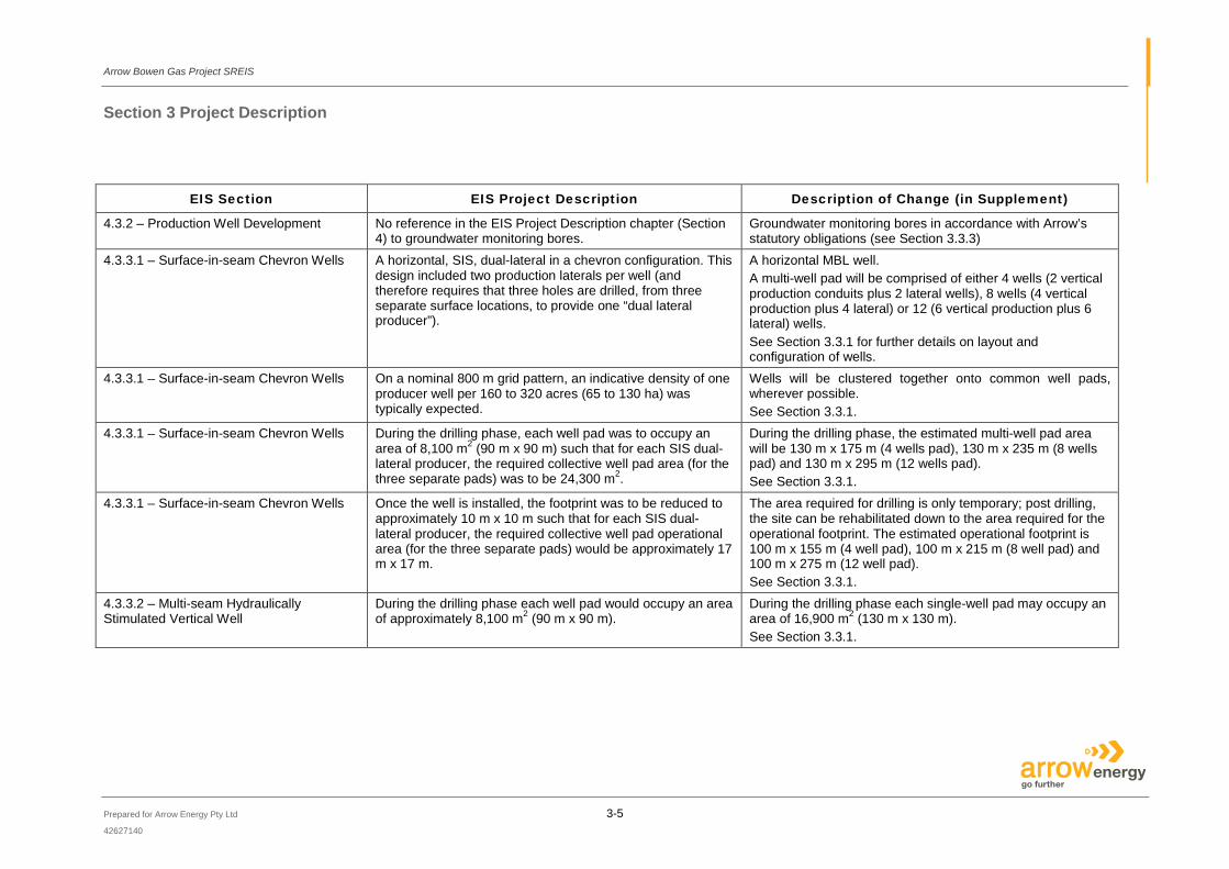
4.3.2 – Production Well Development No reference in the EIS Project Description chapter (Section 4) to groundwater monitoring bores.
Groundwater monitoring bores in accordance with Arrow’s statutory obligations (see Section 3.3.3)
4.3.3.1 – Surface-in-seam Chevron Wells A horizontal, SIS, dual-lateral in a chevron configuration. This design included two production laterals per well (and therefore requires that three holes are drilled, from three separate surface locations, to provide one “dual lateral producer”).
A horizontal MBL well. A multi-well pad will be comprised of either 4 wells (2 vertical production conduits plus 2 lateral wells), 8 wells (4 vertical production plus 4 lateral) or 12 (6 vertical production plus 6 lateral) wells. See Section 3.3.1 for further details on layout and configuration of wells.
4.3.3.1 – Surface-in-seam Chevron Wells On a nominal 800 m grid pattern, an indicative density of one producer well per 160 to 320 acres (65 to 130 ha) was typically expected.
Wells will be clustered together onto common well pads, wherever possible. See Section 3.3.1.
4.3.3.1 – Surface-in-seam Chevron Wells During the drilling phase, each well pad was to occupy an area of 8,100 m2 (90 m x 90 m) such that for each SIS dual-lateral producer, the required collective well pad area (for the three separate pads) was to be 24,300 m2.
During the drilling phase, the estimated multi-well pad area will be 130 m x 175 m (4 wells pad), 130 m x 235 m (8 wells pad) and 130 m x 295 m (12 wells pad). See Section 3.3.1.
4.3.3.1 – Surface-in-seam Chevron Wells Once the well is installed, the footprint was to be reduced to approximately 10 m x 10 m such that for each SIS dual-lateral producer, the required collective well pad operational area (for the three separate pads) would be approximately 17 m x 17 m.
The area required for drilling is only temporary; post drilling, the site can be rehabilitated down to the area required for the operational footprint. The estimated operational footprint is 100 m x 155 m (4 well pad), 100 m x 215 m (8 well pad) and 100 m x 275 m (12 well pad). See Section 3.3.1.
4.3.3.2 – Multi-seam Hydraulically Stimulated Vertical Well
During the drilling phase each well pad would occupy an area of approximately 8,100 m2 (90 m x 90 m).
During the drilling phase each single-well pad may occupy an area of 16,900 m2 (130 m x 130 m). See Section 3.3.1.
Arrow Bowen Gas Project SREIS
Section 3 Project Description
Prepared for Arrow Energy Pty Ltd 3-6 42627140
EIS Section EIS Project Description Description of Change (in Supplement)
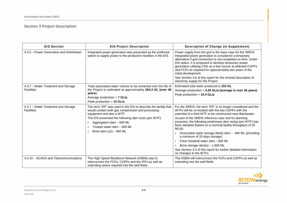
4.3.5 – Power Generation and Distribution Integrated power generation was presented as the preferred option to supply power to the production facilities in the EIS.
Power supply from the grid is the base case for the SREIS. Integrated power generation is considered a temporary alternative if grid connection is not completed on time. Under this option, it is proposed to develop temporary power generation utilising CSG as a fuel source at selected CGPFs and FCFs as required for approximately two years of the initial development. See Section 3.6 of this report for the revised description of electricity supply for the Project.
4.3.7 – Water Treatment and Storage Facilities
Total associated water volume to be extracted over the life of the Project is estimated at approximately 264.3 GL (over 40 years) Average production = 7 GL/a Peak production = 10 GL/a
Estimated total water produced is 153 GL Average production = 4.25 GL/a (average is over 36 years) Peak production = 10.4 GL/a
4.3.7 – Water Treatment and Storage Facilities
The term ‘IPF’ was used in the EIS to describe the facility that would contain both gas compression and processing equipment and also a WTF. The EIS presented the following dam sizes (per WTF): • Aggregation dam – 600 ML • Treated water dam – 600 ML • Brine dam (x2) – 960 ML
For the SREIS, the term ‘IPF’ is no longer considered and the WTFs will be co-located with the two CGPFs with the potential of a third WTF to be constructed near Blackwater. As part of the SREIS reference case and for planning purposes, the following preliminary dam sizing (per WTF) has been adopted (based on a nominal facility throughput of 20 ML/d): • Associated water storage (feed) dam – 400 ML (providing
a minimum of 20 days storage) • Clear (treated) water dam – 600 ML • Brine storage dam(s) – 1,800 ML See Section 3.4 of this report for further detailed information on changes to the WTFs.
4.3.10 – SCADA and Telecommunications The High Speed Backbone Network (HSBN) was to interconnect the FCFs, CGPFs and the IPFs as well as extending where required into the well fields.
The HSBN will interconnect the FCFs and CGPFs as well as extending into the well fields.
Arrow Bowen Gas Project SREIS
Section 3 Project Description
Prepared for Arrow Energy Pty Ltd 3-7 42627140
EIS Section EIS Project Description Description of Change (in Supplement)
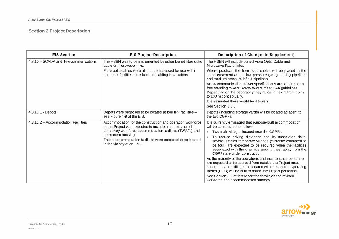
4.3.10 – SCADA and Telecommunications The HSBN was to be implemented by either buried fibre optic cable or microwave links. Fibre optic cables were also to be assessed for use within upstream facilities to reduce site cabling installations.
The HSBN will include buried Fibre Optic Cable and Microwave Radio links. Where practical, the fibre optic cables will be placed in the same easement as the low pressure gas gathering pipelines and medium pressure infield pipelines. Arrow communications tower specifications are for long term free standing towers. Arrow towers meet CAA guidelines. Depending on the geography they range in height from 65 m to 100 m conceptually. It is estimated there would be 4 towers. See Section 3.8.5.
4.3.11.1 - Depots Depots were proposed to be located at four IPF facilities – see Figure 4-9 of the EIS.
Depots (including storage yards) will be located adjacent to the two CGPFs.
4.3.11.2 – Accommodation Facilities Accommodation for the construction and operation workforce of the Project was expected to include a combination of temporary workforce accommodation facilities (TWAFs) and permanent housing. These accommodation facilities were expected to be located in the vicinity of an IPF.
It is currently envisaged that purpose-built accommodation will be constructed as follows: • Two main villages located near the CGPFs. • To reduce driving distances and its associated risks,
several smaller temporary villages (currently estimated to be four) are expected to be required when the facilities associated with the drainage area furthest away from the CGPFs are under construction.
As the majority of the operations and maintenance personnel are expected to be sourced from outside the Project area, accommodation villages co-located with the Central Operating Bases (COB) will be built to house the Project personnel. See Section 3.9 of this report for details on the revised workforce and accommodation strategy.
Arrow Bowen Gas Project SREIS
Section 3 Project Description
Prepared for Arrow Energy Pty Ltd 3-8 42627140
EIS Section EIS Project Description Description of Change (in Supplement)
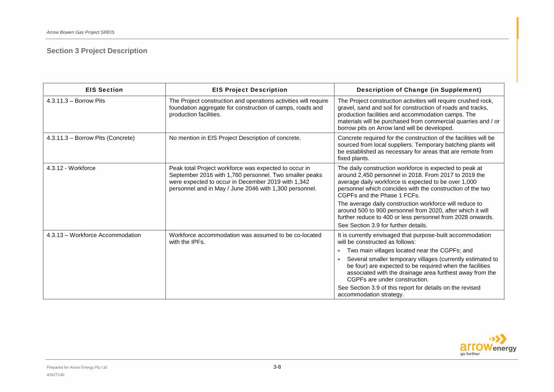
4.3.11.3 – Borrow Pits The Project construction and operations activities will require foundation aggregate for construction of camps, roads and production facilities.
The Project construction activities will require crushed rock, gravel, sand and soil for construction of roads and tracks, production facilities and accommodation camps. The materials will be purchased from commercial quarries and / or borrow pits on Arrow land will be developed.
4.3.11.3 – Borrow Pits (Concrete) No mention in EIS Project Description of concrete. Concrete required for the construction of the facilities will be sourced from local suppliers. Temporary batching plants will be established as necessary for areas that are remote from fixed plants.
4.3.12 - Workforce Peak total Project workforce was expected to occur in September 2016 with 1,760 personnel. Two smaller peaks were expected to occur in December 2019 with 1,342 personnel and in May / June 2046 with 1,300 personnel.
The daily construction workforce is expected to peak at around 2,450 personnel in 2018. From 2017 to 2019 the average daily workforce is expected to be over 1,000 personnel which coincides with the construction of the two CGPFs and the Phase 1 FCFs. The average daily construction workforce will reduce to around 500 to 900 personnel from 2020, after which it will further reduce to 400 or less personnel from 2028 onwards. See Section 3.9 for further details.
4.3.13 – Workforce Accommodation Workforce accommodation was assumed to be co-located with the IPFs.
It is currently envisaged that purpose-built accommodation will be constructed as follows: • Two main villages located near the CGPFs; and • Several smaller temporary villages (currently estimated to
be four) are expected to be required when the facilities associated with the drainage area furthest away from the CGPFs are under construction.
See Section 3.9 of this report for details on the revised accommodation strategy.

Arrow Bowen Gas Project SREIS
Section 3 Project Description
Prepared for Arrow Energy Pty Ltd 3-9 42627140
EIS Section EIS Project Description Description of Change (in Supplement)
4.4 – Development Planning For the purpose of the EIS, production facility locations were assumed to be located somewhere near the centre of each development area (17 in total) of 12 km radius. The indicative layout of production facilities across the Project area were presented in Figure 4-4 of the EIS.
Due to expected low gas pressures, as a result of the preliminary engineering undertaken in the concept select phase, the number of development (or drainage) areas has increased to 33 in total, however; each of these drainage areas now represent an approximate 6 km radius catchment area for gathering well production (gas and water), and distributing to surface production facilities located at or near the centre of drainage area. These 33 drainage areas will be developed over the Project life, however; Arrow does not expect all facilities to be operating together at one single time. See Figure 3–1. The number and location of development areas has been revised – this influences the indicative location of facilities. This change is now presented in Figure 3–1. See Section 3.2 of this report for details on the revised development planning and sequencing for the Project.
4.5 – Development Sequence 14 development regions were presented in the EIS.
The overall Project development area has been sub-divided into 9 development regions (see Figure 3–1). See Section 3.2 of this report for details on the revised development planning and sequencing for the Project.
4.6 - Construction No outline of pipeline crossing construction techniques The SREIS case presents three options for pipeline crossings depending on the nature of each specific crossing: • Open cut; • Horizontal directional drilling; and • Bored. See Section 3.7.6 for detailed on the types of construction for pipeline crossings.
Arrow Bowen Gas Project SREIS
Section 3 Project Description
Prepared for Arrow Energy Pty Ltd 3-10 42627140
EIS Section EIS Project Description Description of Change (in Supplement)
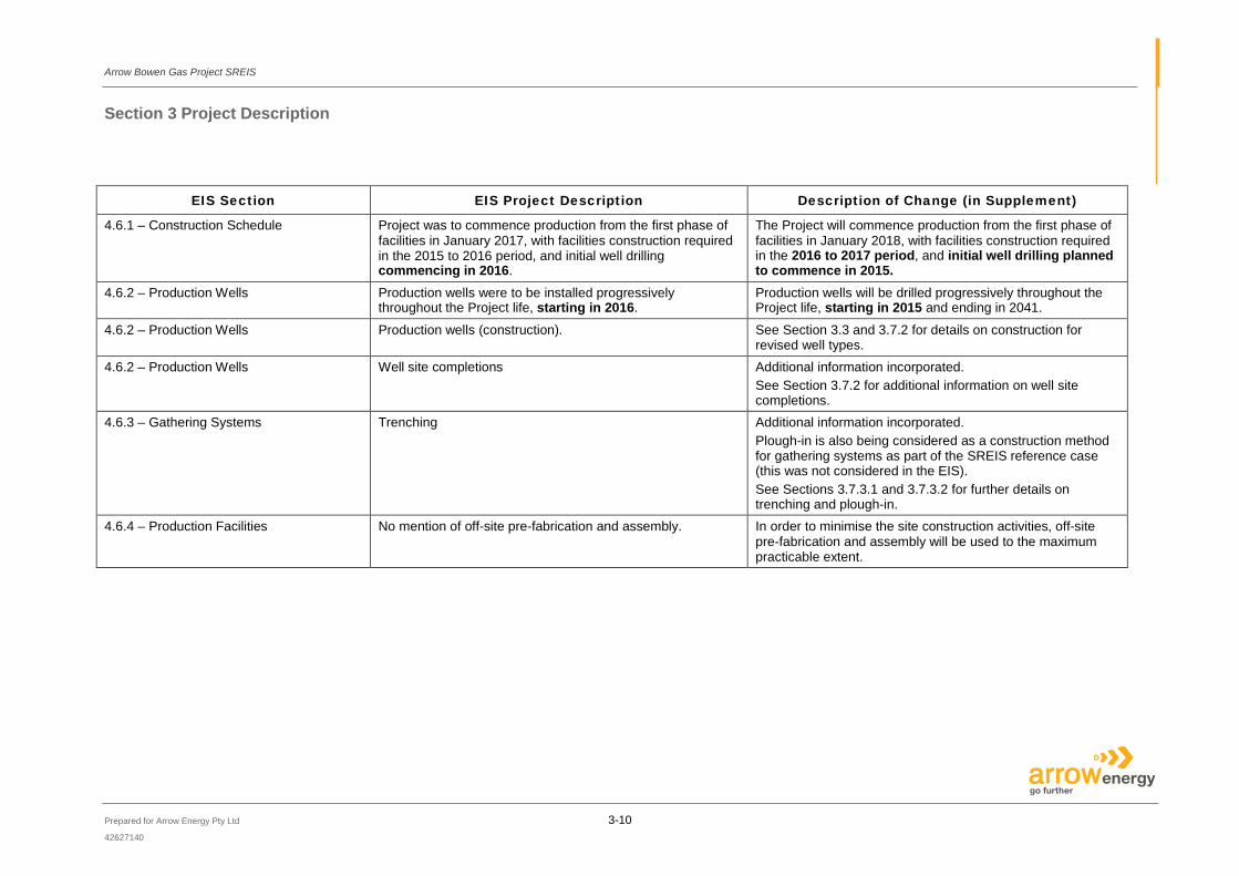
4.6.1 – Construction Schedule Project was to commence production from the first phase of facilities in January 2017, with facilities construction required in the 2015 to 2016 period, and initial well drilling commencing in 2016.
The Project will commence production from the first phase of facilities in January 2018, with facilities construction required in the 2016 to 2017 period, and initial well drilling planned to commence in 2015.
4.6.2 – Production Wells Production wells were to be installed progressively throughout the Project life, starting in 2016.
Production wells will be drilled progressively throughout the Project life, starting in 2015 and ending in 2041.
4.6.2 – Production Wells Production wells (construction). See Section 3.3 and 3.7.2 for details on construction for revised well types.
4.6.2 – Production Wells Well site completions Additional information incorporated. See Section 3.7.2 for additional information on well site completions.
4.6.3 – Gathering Systems Trenching Additional information incorporated. Plough-in is also being considered as a construction method for gathering systems as part of the SREIS reference case (this was not considered in the EIS). See Sections 3.7.3.1 and 3.7.3.2 for further details on trenching and plough-in.
4.6.4 – Production Facilities No mention of off-site pre-fabrication and assembly. In order to minimise the site construction activities, off-site pre-fabrication and assembly will be used to the maximum practicable extent.
Arrow Bowen Gas Project SREIS
Section 3 Project Description
Prepared for Arrow Energy Pty Ltd 3-11 42627140
EIS Section EIS Project Description Description of Change (in Supplement)
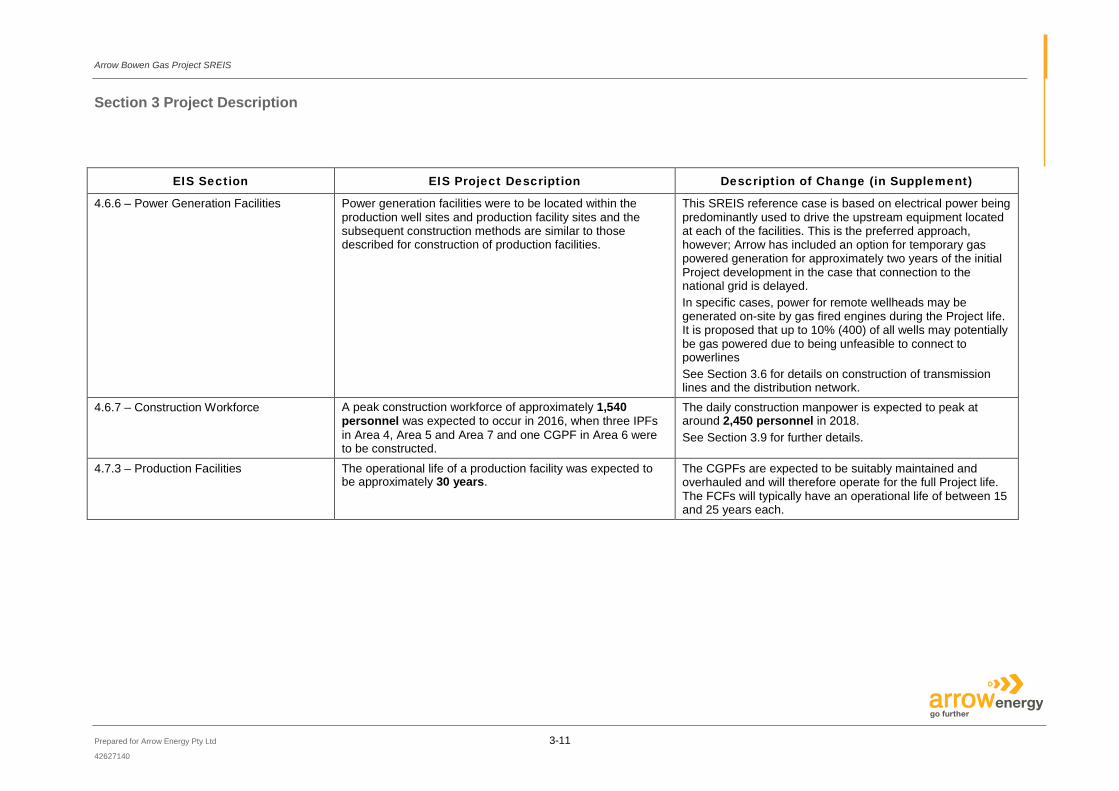
4.6.6 – Power Generation Facilities Power generation facilities were to be located within the production well sites and production facility sites and the subsequent construction methods are similar to those described for construction of production facilities.
This SREIS reference case is based on electrical power being predominantly used to drive the upstream equipment located at each of the facilities. This is the preferred approach, however; Arrow has included an option for temporary gas powered generation for approximately two years of the initial Project development in the case that connection to the national grid is delayed. In specific cases, power for remote wellheads may be generated on-site by gas fired engines during the Project life. It is proposed that up to 10% (400) of all wells may potentially be gas powered due to being unfeasible to connect to powerlines See Section 3.6 for details on construction of transmission lines and the distribution network.
4.6.7 – Construction Workforce A peak construction workforce of approximately 1,540 personnel was expected to occur in 2016, when three IPFs in Area 4, Area 5 and Area 7 and one CGPF in Area 6 were to be constructed.
The daily construction manpower is expected to peak at around 2,450 personnel in 2018. See Section 3.9 for further details.
4.7.3 – Production Facilities The operational life of a production facility was expected to be approximately 30 years.
The CGPFs are expected to be suitably maintained and overhauled and will therefore operate for the full Project life. The FCFs will typically have an operational life of between 15 and 25 years each.
Arrow Bowen Gas Project SREIS
Section 3 Project Description
Prepared for Arrow Energy Pty Ltd 3-12 42627140
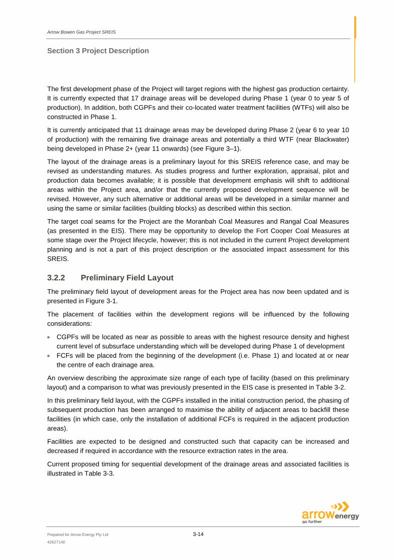
The following sections describe in detail the revisions to the Project listed above:
• Revised Development Planning and Sequencing; • Change to Number, Type and Layout of Wells; • Water Treatment Facilities (Co-located with CGPF); • Revised Strategy for Water Management; • Changes to Supply of Electricity; • Changes to Construction Techniques; • Operations and Maintenance Changes; and • Changes to Workforce and Accommodation Strategy.
3.2 Revised Development Plan and Sequencing
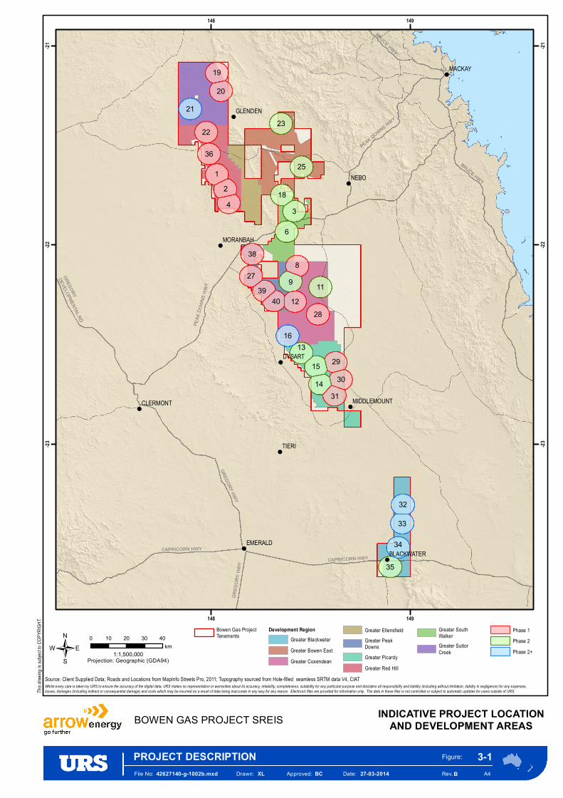
3.2.1 Development Regions and Drainage Areas Field development has advanced since publication of the EIS, with the overall project development area now being subdivided into nine development regions (reduced from the 14 presented in the EIS) to enable a phased approach to exploration; appraisal, piloting and development. These development regions have been further separated into 33 smaller drainage areas (Figure 3-1).
The number of drainage areas has increased for the purpose of the SREIS from 17 presented in the EIS, however, the radius of each drainage circle has decreased in size from 12 km to 6 km.
The 33 drainage areas are presented in Figure 3-1 as circles. Each of these circles represents a typical 6 km radius catchment area for locating production wells and the gathering network for the transmission of gas and water to surface production facilities located at or near the centre of each circle. Each of these centrally located surface production facilities will be an FCF (33 in total). Note that the actual size and shape of each catchment area is indicative and may vary from the 6 km radius circles shown depending on the local gathering network.
Over the life of the Project, the planning basis is that two CGPFs will be installed. Both will treat the gas to pipeline specification. One CGPF will service the drainage areas in the north, whilst the second will service the drainage areas in the south of the Project area. The indicative location of these two CGPFs is presented in Figure 3-1.
Facilities to be constructed within the drainage areas include:
• Wells; • Wellhead facilities; • Low pressure water and gas gathering systems; • FCFs (to boost the gas pressure for export to the CGPF); • WTSs located with the FCF (to pump the water for transfer to the WTF); • Raw water trunkline for transport of raw water to the WTFs; • Medium pressure infield pipelines (to transport the gas from the FCF to the CGPF); and • Infrastructure required for power distribution.
!
!
!
!
!
!
!
!
!
!
GREG
ORY
HWY
PEAK DOWNS HWY
BRUCE HWY
CAPRICORN HWY
GREGORY HWY
PEAK
DOW
NS H
WY
CAPRICORN HWY
BRUCE HWY
GREGORY
DEVELOPMENTAL RD
Kenmare Nature Refuge
NEBO
TIERI
DYSART
MACKAY
EMERALD
GLENDEN
CLERMONT
MORANBAH
BLACKWATER
MIDDLEMOUNT
6
3
1
89
42
11
35
34
16
28
38
2536
2223
21
18
13
27
12
33
32
20
19
291514
3130
4039
148
148
149
149
-23 -23
-22 -22
-21 -21
/
File No:
PROJECT DESCRIPTION42627140-g-1002b.mxd Drawn: XL Approved: BC Date: 27-03-2014
Figure:
A4
3-1
BOWEN GAS PROJECT SREIS INDICATIVE PROJECT LOCATIONAND DEVELOPMENT AREAS
Whilst every care is taken by URS to ensure the accuracy of the digital data, URS makes no representation or warranties about its accuracy, reliability, completeness, suitability for any particular purpose and disclaims all responsibility and liability (including without limitation, liability in negligence) for any expenses,losses, damages (including indirect or consequential damage) and costs which may be incurred as a result of data being inaccurate in any way for any reason. Electronic files are provided for information only. The data in these files is not controlled or subject to automatic updates for users outside of URS.
Source: Client Supplied Data; Roads and Locations from MapInfo Streets Pro, 2011; Topography sourced from Hole-filled seamless SRTM data V4, CIAT
This d
rawing
is sub
ject to
COPY
RIGHT
.
Rev. B
Bowen Gas ProjectTenements
Development RegionGreater BlackwaterGreater Bowen EastGreater Coxendean
Greater EllensfieldGreater PeakDownsGreater PicardyGreater Red Hill
Greater SouthWalkerGreater SuttorCreek
Phase 1Phase 2Phase 2+
0 10 20 30 40km
1:1,500,000Projection: Geographic (GDA94)
Arrow Bowen Gas Project SREIS
Section 3 Project Description
Prepared for Arrow Energy Pty Ltd 3-14 42627140
The first development phase of the Project will target regions with the highest gas production certainty. It is currently expected that 17 drainage areas will be developed during Phase 1 (year 0 to year 5 of production). In addition, both CGPFs and their co-located water treatment facilities (WTFs) will also be constructed in Phase 1.
It is currently anticipated that 11 drainage areas may be developed during Phase 2 (year 6 to year 10 of production) with the remaining five drainage areas and potentially a third WTF (near Blackwater) being developed in Phase 2+ (year 11 onwards) (see Figure 3–1).
The layout of the drainage areas is a preliminary layout for this SREIS reference case, and may be revised as understanding matures. As studies progress and further exploration, appraisal, pilot and production data becomes available; it is possible that development emphasis will shift to additional areas within the Project area, and/or that the currently proposed development sequence will be revised. However, any such alternative or additional areas will be developed in a similar manner and using the same or similar facilities (building blocks) as described within this section.
The target coal seams for the Project are the Moranbah Coal Measures and Rangal Coal Measures (as presented in the EIS). There may be opportunity to develop the Fort Cooper Coal Measures at some stage over the Project lifecycle, however; this is not included in the current Project development planning and is not a part of this project description or the associated impact assessment for this SREIS.
3.2.2 Preliminary Field Layout The preliminary field layout of development areas for the Project area has now been updated and is presented in Figure 3-1.
The placement of facilities within the development regions will be influenced by the following considerations:
• CGPFs will be located as near as possible to areas with the highest resource density and highest current level of subsurface understanding which will be developed during Phase 1 of development
• FCFs will be placed from the beginning of the development (i.e. Phase 1) and located at or near the centre of each drainage area.
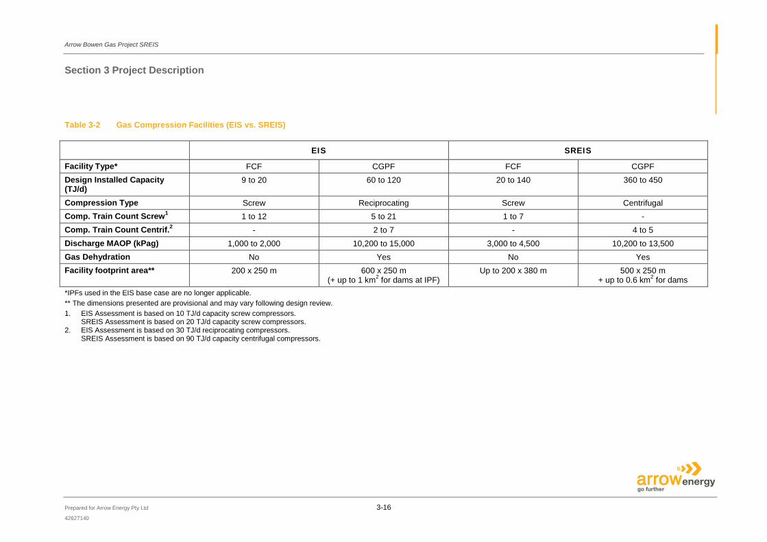
An overview describing the approximate size range of each type of facility (based on this preliminary layout) and a comparison to what was previously presented in the EIS case is presented in Table 3-2.
In this preliminary field layout, with the CGPFs installed in the initial construction period, the phasing of subsequent production has been arranged to maximise the ability of adjacent areas to backfill these facilities (in which case, only the installation of additional FCFs is required in the adjacent production areas).
Facilities are expected to be designed and constructed such that capacity can be increased and decreased if required in accordance with the resource extraction rates in the area.
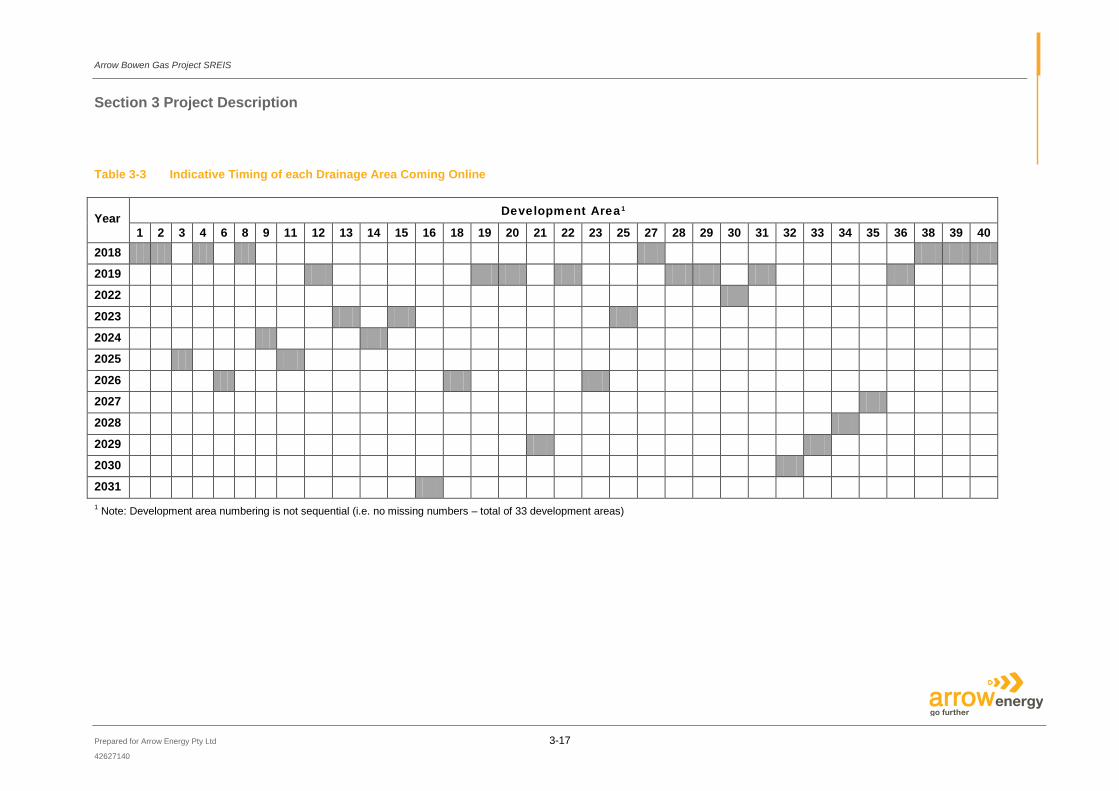
Current proposed timing for sequential development of the drainage areas and associated facilities is illustrated in Table 3-3.

Arrow Bowen Gas Project SREIS
Section 3 Project Description
Prepared for Arrow Energy Pty Ltd 3-15 42627140
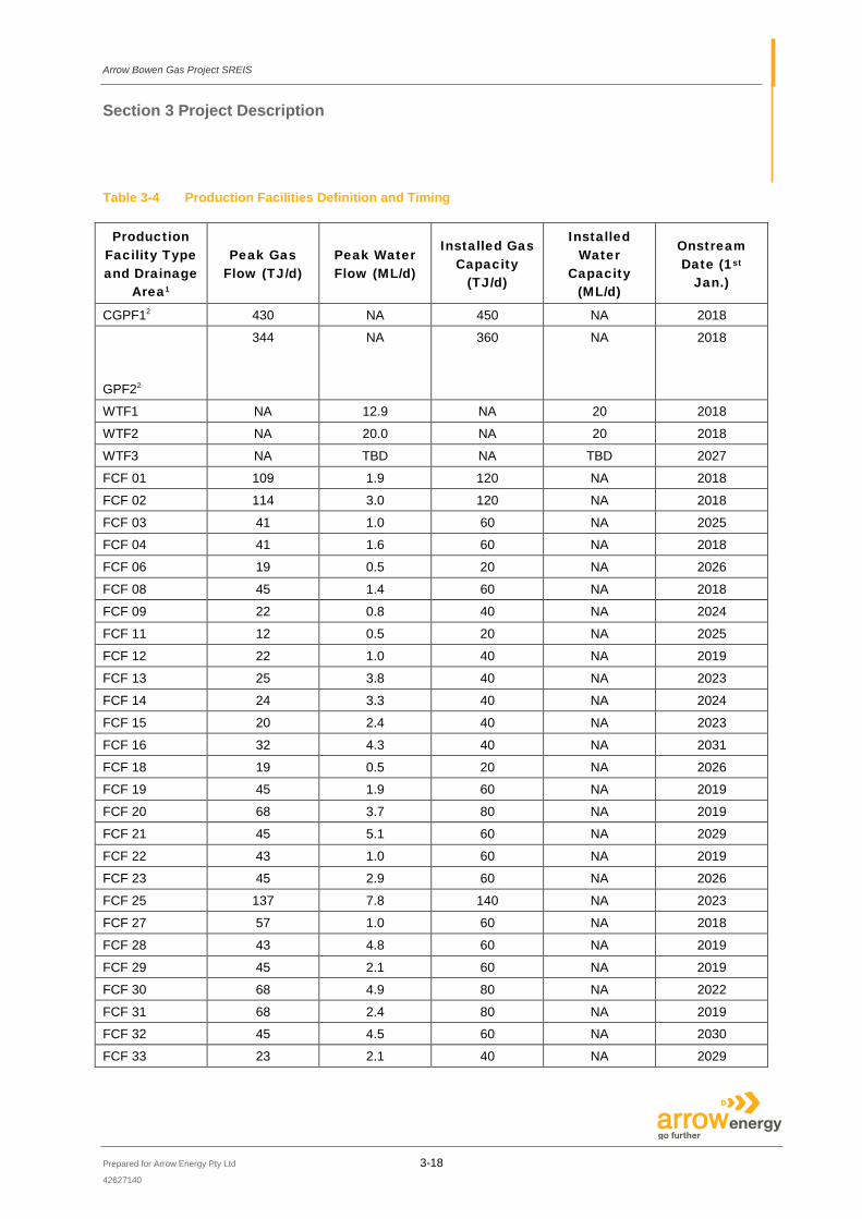
Table 3-4 provides further detail on the expected peak gas flow, peak water flow, installed gas capacity and onstream date.
Arrow Bowen Gas Project SREIS
Section 3 Project Description
Prepared for Arrow Energy Pty Ltd 3-16 42627140
Table 3-2 Gas Compression Facilities (EIS vs. SREIS)
EIS SREIS Facility Type* FCF CGPF FCF CGPF Design Installed Capacity (TJ/d)
9 to 20 60 to 120 20 to 140 360 to 450
Compression Type Screw Reciprocating Screw Centrifugal
Comp. Train Count Screw1 1 to 12 5 to 21 1 to 7 -
Comp. Train Count Centrif.2 - 2 to 7 - 4 to 5
Discharge MAOP (kPag) 1,000 to 2,000 10,200 to 15,000 3,000 to 4,500 10,200 to 13,500
Gas Dehydration No Yes No Yes
Facility footprint area** 200 x 250 m 600 x 250 m (+ up to 1 km2 for dams at IPF)
Up to 200 x 380 m 500 x 250 m + up to 0.6 km2 for dams
*IPFs used in the EIS base case are no longer applicable. ** The dimensions presented are provisional and may vary following design review. 1. EIS Assessment is based on 10 TJ/d capacity screw compressors.
SREIS Assessment is based on 20 TJ/d capacity screw compressors. 2. EIS Assessment is based on 30 TJ/d reciprocating compressors.
SREIS Assessment is based on 90 TJ/d capacity centrifugal compressors.
Arrow Bowen Gas Project SREIS
Section 3 Project Description
Prepared for Arrow Energy Pty Ltd 3-17 42627140
Table 3-3 Indicative Timing of each Drainage Area Coming Online
Year Development Area1
1 2 3 4 6 8 9 11 12 13 14 15 16 18 19 20 21 22 23 25 27 28 29 30 31 32 33 34 35 36 38 39 40 2018 2019 2022 2023 2024 2025 2026 2027 2028 2029 2030 2031 1 Note: Development area numbering is not sequential (i.e. no missing numbers – total of 33 development areas)
Arrow Bowen Gas Project SREIS
Section 3 Project Description
Prepared for Arrow Energy Pty Ltd 3-18
42627140
Table 3-4 Production Facilities Definition and Timing
Production Facility Type and Drainage
Area1
Peak Gas Flow (TJ/d)
Peak Water Flow (ML/d)
Installed Gas Capacity
(TJ/d)
Installed Water
Capacity (ML/d)
Onstream Date (1st
Jan.)
CGPF12 430 NA 450 NA 2018
GPF22
344 NA 360 NA 2018
WTF1 NA 12.9 NA 20 2018
WTF2 NA 20.0 NA 20 2018
WTF3 NA TBD NA TBD 2027
FCF 01 109 1.9 120 NA 2018
FCF 02 114 3.0 120 NA 2018
FCF 03 41 1.0 60 NA 2025
FCF 04 41 1.6 60 NA 2018
FCF 06 19 0.5 20 NA 2026
FCF 08 45 1.4 60 NA 2018
FCF 09 22 0.8 40 NA 2024
FCF 11 12 0.5 20 NA 2025
FCF 12 22 1.0 40 NA 2019
FCF 13 25 3.8 40 NA 2023
FCF 14 24 3.3 40 NA 2024
FCF 15 20 2.4 40 NA 2023
FCF 16 32 4.3 40 NA 2031
FCF 18 19 0.5 20 NA 2026
FCF 19 45 1.9 60 NA 2019
FCF 20 68 3.7 80 NA 2019
FCF 21 45 5.1 60 NA 2029
FCF 22 43 1.0 60 NA 2019
FCF 23 45 2.9 60 NA 2026
FCF 25 137 7.8 140 NA 2023
FCF 27 57 1.0 60 NA 2018
FCF 28 43 4.8 60 NA 2019
FCF 29 45 2.1 60 NA 2019
FCF 30 68 4.9 80 NA 2022
FCF 31 68 2.4 80 NA 2019
FCF 32 45 4.5 60 NA 2030
FCF 33 23 2.1 40 NA 2029

Arrow Bowen Gas Project SREIS
Section 3 Project Description
Prepared for Arrow Energy Pty Ltd 3-19
42627140
Production Facility Type and Drainage
Area1
Peak Gas Flow (TJ/d)
Peak Water Flow (ML/d)
Installed Gas Capacity
(TJ/d)
Installed Water
Capacity (ML/d)
Onstream Date (1st
Jan.)
FCF 34 45 5.1 60 NA 2028
FCF 35 68 3.0 80 NA 2027
FCF 36 88 0.8 100 NA 2019
FCF 38 38 0.6 40 NA 2018
FCF 39 57 1.4 60 NA 2018
FCF 40 38 1.9 40 NA 2018 1 Note: Development area numbering is not sequential (i.e. no missing numbers – total of 33 development areas) 2 The two CGPFs receive gas from each drainage area via a FCF.
3.3 Change to Number, Type and Layout of Wells Since the publication of the EIS, the well types proposed have been revised and the development plan for use as the SREIS reference case involves drilling and completion of two base case well types:
• MBLs: multi branched horizontal wells (lateral well) drilled in-seam to intersect a vertical producer (vertical production conduit); the lateral section of such wells will be completed either open-hole or with fibreglass / composite liner; and
• Multi-seam hydraulically stimulated: vertical, cased and cemented wells, which are perforated and fracture-stimulated to provide formation access (as presented in the EIS).
In the region of 4,000 production wells will be drilled throughout the Project area over the approximate 40 year life to maintain gas feed to the LNG plant. Each production well is expected to have an average life of 25 years.
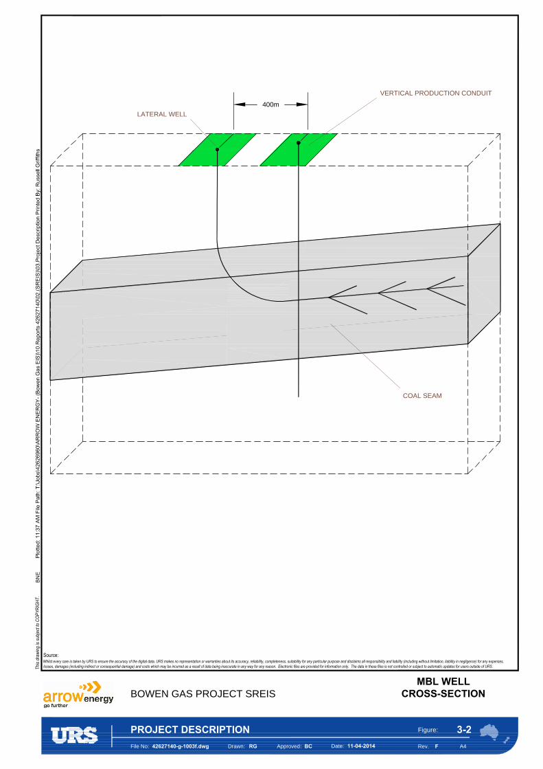
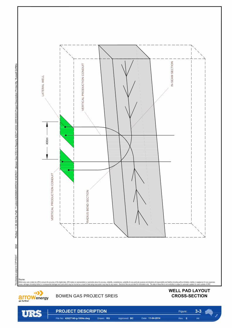
3.3.1 Multi Branch Lateral Wells Traditionally, vertical wells are used in CSG developments whereby a single well is drilled vertically from the ground surface to the target coal seams. The Arrow SREIS base case design is a horizontal MBL well (see Figure 3-2).
In CSG developments the term “horizontal” is primarily used to describe “in-seam” drilling, where a well trajectory is maintained within a single coal seam.
A horizontal ‘lateral’ well is drilled from one well pad to the target coal seam and then geo-steered in-seam to intersect a previously drilled vertical production conduit at a corresponding mirrored well pad, approximately 400 m away. After intersecting the vertical production conduit, a number of open-hole ‘side-tracks’ (laterals) are constructed within the coal seam (see Figure 3-2). The lateral well provides a pathway for both gas and water to drain and enter the vertical well. The vertical well acts as a production conduit for pumping gas and water to the surface.
Arrow Bowen Gas Project SREIS
Section 3 Project Description
Prepared for Arrow Energy Pty Ltd 3-20
42627140
The multi-branch configuration significantly improves reservoir drainage whilst reducing the requirement for dedicated horizontal holes drilled from the surface (i.e. reducing the development surface footprint).
All lateral well sections are completed either open-hole, or with a slotted composite liner. The production section of the vertical production conduit is generally under-reamed, exposing the coal formation; a tubing-conveyed artificial lift system will be installed below this interval to facilitate water production to surface.
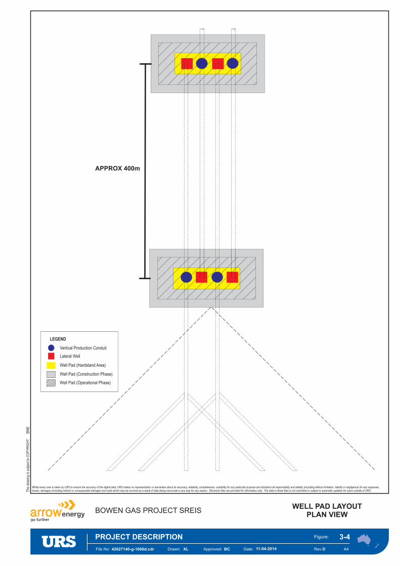
Each well pad for the MBL development scenario will typically be a multi-well pad (i.e. more than one well per pad). A well pad will typically consist of both lateral wells and vertical production conduits and will be mirrored by an additional well pad (with the same number of wells) approximately 400 m apart (see Figure 3-3 and Figure 3-4).
At multi-well pad sites, each vertical conduit will have an artificial lift system (pump) and production control and metering skid. It is envisaged that the wells will be aligned at the surface in a row.
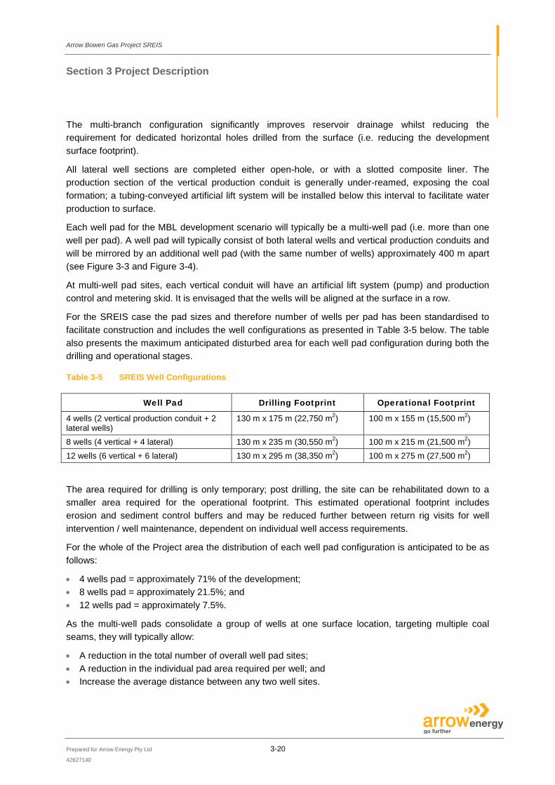
For the SREIS case the pad sizes and therefore number of wells per pad has been standardised to facilitate construction and includes the well configurations as presented in Table 3-5 below. The table also presents the maximum anticipated disturbed area for each well pad configuration during both the drilling and operational stages.
Table 3-5 SREIS Well Configurations
Well Pad Drilling Footprint Operational Footprint
4 wells (2 vertical production conduit + 2 lateral wells)
130 m x 175 m (22,750 m2) 100 m x 155 m (15,500 m2)
8 wells (4 vertical + 4 lateral) 130 m x 235 m (30,550 m2) 100 m x 215 m (21,500 m2) 12 wells (6 vertical + 6 lateral) 130 m x 295 m (38,350 m2) 100 m x 275 m (27,500 m2)
The area required for drilling is only temporary; post drilling, the site can be rehabilitated down to a smaller area required for the operational footprint. This estimated operational footprint includes erosion and sediment control buffers and may be reduced further between return rig visits for well intervention / well maintenance, dependent on individual well access requirements.
For the whole of the Project area the distribution of each well pad configuration is anticipated to be as follows:
• 4 wells pad = approximately 71% of the development; • 8 wells pad = approximately 21.5%; and • 12 wells pad = approximately 7.5%.
As the multi-well pads consolidate a group of wells at one surface location, targeting multiple coal seams, they will typically allow:
• A reduction in the total number of overall well pad sites; • A reduction in the individual pad area required per well; and • Increase the average distance between any two well sites.
COAL SEAM
LATERAL WELL
VERTICAL PRODUCTION CONDUIT
400m
BN
E
Whilst every care is taken by URS to ensure the accuracy of the digital data, URS makes no representation or warranties about its accuracy, reliability, completeness, suitability for any particular purpose and disclaims all responsibility and liability (including without limitation, liability in negligence) for any expenses,losses, damages (including indirect or consequential damage) and costs which may be incurred as a result of data being inaccurate in any way for any reason. Electronic files are provided for information only. The data in these files is not controlled or subject to automatic updates for users outside of URS.Th
is dr
awing
is su
bject
to C
OPYR
IGHT
.
Source:
File No:Date:
Drawn: Approved:
Figure:
Rev. A4
BOWEN GAS PROJECT SREIS
PROJECT DESCRIPTION
MBL WELL
CROSS-SECTION
F42627140-g-1003f.dwg
RA
DIU
S B
EN
D S
EC
TIO
N
VE
RT
IC
AL P
RO
DU
CT
IO
N C
ON
DU
IT
IN
-S
EA
M S
EC
TIO
N
VE
RT
IC
AL P
RO
DU
CT
IO
N C
ON
DU
IT
LA
TE
RA
L W
ELL
400m
BN
E
Whilst every care is taken by URS to ensure the accuracy of the digital data, URS makes no representation or warranties about its accuracy, reliability, completeness, suitability for any particular purpose and disclaims all responsibility and liability (including without limitation, liability in negligence) for any expenses,losses, damages (including indirect or consequential damage) and costs which may be incurred as a result of data being inaccurate in any way for any reason. Electronic files are provided for information only. The data in these files is not controlled or subject to automatic updates for users outside of URS.Th
is dr
awing
is su
bject
to C
OPYR
IGHT
.
Source:
File No:Date:
Drawn: Approved:
Figure:
Rev. A4
BOWEN GAS PROJECT SREIS
PROJECT DESCRIPTION
WELL PAD LAYOUT
CROSS-SECTION
E42627140-g-1004e.dwg
File No: Date:Approved:Drawn: Rev.
Figure:
A442627140-g-1006d.cdr 11-04-2014BCXL
WELL PAD LAYOUTPLAN VIEW
D
PROJECT DESCRIPTION 3-4
BN
E
Whilst every care is taken by URS to ensure the accuracy of the digital data, URS makes no representation or warranties about its accuracy, reliability, completeness, suitability for any particular purpose and disclaims all responsibility and liability (including without limitation, liability in negligence) for any expenses,losses, damages (including indirect or consequential damage) and costs which may be incurred as a result of data being inaccurate in any way for any reason. Electronic files are provided for information only. The data in these files is not controlled or subject to automatic updates for users outside of URS.
BOWEN GAS PROJECT SREIS
Thi
sdr
awin
gis
subj
ect t
oC
OP
YR
IGH
T.
APPROX 400m
LEGEND
Vertical Production Conduit
Lateral Well
Well Pad (Hardstand Area)
Well Pad (Construction Phase)
Well Pad (Operational Phase)
Arrow Bowen Gas Project SREIS
Section 3 Project Description
Prepared for Arrow Energy Pty Ltd 3-24
42627140
3.3.2 Hydraulically Stimulated Vertical Well If required, approximately 1,000 (part of the 4,000 proposed) wells may be developed utilising hydraulic stimulation. If this occurs it would only be in the latter stages of the Project development. Further assessment of hydraulically stimulated wells would be presented as part of the EA approvals process. This would include development of a site specific execution plan for hydraulic stimulation near known faults detailing: well numbers, type and location; number of multi-seamed wells to be constructed; grid spacing, potential for multiple simulation events; and details of storage facilities. A well-specific risk assessment will also be developed, which will take into consideration the informational requirements of the EA. In addition to the risk assessment, Arrow is commited to the development of a stimulation impact monitoring program for each hydraulic stimulation campaign carried out. It should be noted that the well pad dimensions presented in this document are specifically for the MBL well type and may need to be revised to accommodate hydraulic stimulation operations.
3.3.3 Water Monitoring Bores Formation pressure and water quality monitoring tasks for the project are driven by both regulatory requirements (i.e. Underground Water Impact Report for the Government and Water Act 2000 obligations) and Arrow’s Project requirements (i.e. groundwater modelling and CSG reservoir engineering).
A water monitoring program will be established across the entire well field, so as to allow for tracking of water production and quality at all stages of handling. Key elements of this program will be:
• Well monitoring: each well will be fitted with instrumentation to allow for monitoring and measurement of water production;
• Stored water monitoring: to be conducted in all water storages, including before and after reverse osmosis, to ensure compliance with EA requirements; and
• Underground water impact monitoring and assessment: this will be conducted in accordance with the regulatory requirements for the Project. Further detail on the proposed bore water monitoring program is outlined in the Groundwater chapter (Section 7) and Groundwater Technical Report (Appendix E) of the SREIS.
3.4 Water Treatment Facilities (Co-located with CGPF) The term integrated processing facility (IPF) is no longer being used as part of the SREIS reference case. WTFs for the treatment of associated water, storage of brine, and temporary storage of treated water will be located at the two CGPFs north and south of Moranbah, in drainage area’s #2 and #40, with a potential third WTF that may be commissioned in Phase 2+ located near Blackwater in drainage area #34 (Figure 3-1). This is a reduction from the number of major facilities proposed in the EIS and consequently reduces the footprint of facilities required over the Project area.
Produced water from drainage areas will be degassed and directed to a feed water dam adjacent to the WTF. The feed dam is an important part of the treatment process as it allows for surge capacity,

Arrow Bowen Gas Project SREIS
Section 3 Project Description
Prepared for Arrow Energy Pty Ltd 3-25
42627140
sediment settlement, homogenous mixing, liberation of residual volatile compounds and oxidation of some organics and metals.
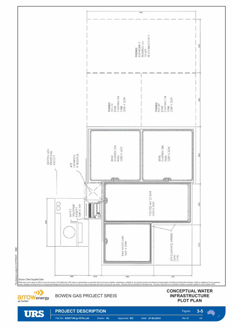
From the feed water dam, water will be transferred into the pre-treatment stage of the WTF. Reverse osmosis technology is currently considered the most appropriate treatment process coupled with suitable pre-treatment such as membrane or media filtration and hardness removal. Investigation and evaluation of new and emerging technologies will continue to determine applicability to operations based on economics, energy consumption, brine recovery, regulations and operational and environmental footprint of the associated technology. A conceptual layout of the WTF footprint is provided in Figure 3-5.
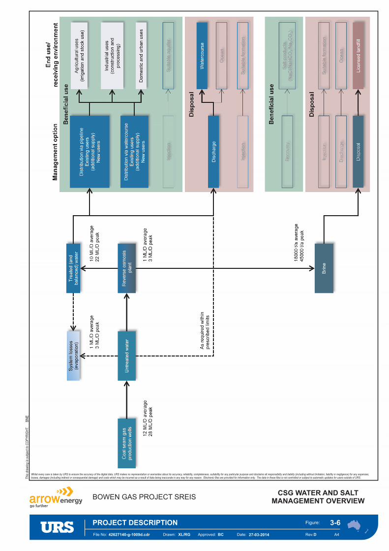
Treatment will produce appropriate quality water for the available water management options. Treated water will be stored in treated water dams and then distributed to water management options outlined in the CSG Water and Salt Management Strategy (Appendix D) of this SREIS. An overview of the possible water management options and associated end uses is outlined in the conceptual CSG water and salt management overview presented in Figure 3-6.
Brine from the WTF will be discharged into brine dams, where the brine will evaporate to a solid waste product before being disposed of in one or more Regulated Waste Facilities (RWFs) (suitably licensed landfills). As a possible optimisation, enhanced evaporation options, applying thermal, chemical and/or mechanical assistance to reduce storage requirements, will be considered.
Transfer infrastructure will be installed to allow transfer of raw water between the treatment facilities.
WTFs may be designed in a modular configuration to enable the size of each facility to better match local demand. A modular approach provides the ability to relocate facilities during the Project life to accommodate changing water production volumes as the field develops. This will prevent significant over design and capitalisation of total water treatment capacity. Some excess capacity will be unavoidable and will be further assessed and quantified during the next phase of engineering definition.
In addition to WTFs there is a requirement for storage to manage water through the collection, treatment and disposal phases. Storage volumes will be determined based on life cycle water balance to take into account the amount and quality of water produced in the field, the process capacity of WTFs, evaporation and rainfall.
The WTFs are expected to have a 25-year design life and operate 24 hours per day, seven days per week. However the facilities will be overhauled and maintained as required to run for the life of the Project. They will be fully automated and designed for minimal operator intervention. The facilities will be controlled and their integrity remotely monitored by a computer-based integrated control system that includes process and safety controls. Operators will be notified by warnings and alarms of changes in key operating parameters.
Typical operations and maintenance tasks at the WTFs will include:
• Routine inspection; • Maintenance (cleaning, lubrication and replacement of filters); • Chemical delivery; • Solid waste disposal;

Arrow Bowen Gas Project SREIS
Section 3 Project Description
Prepared for Arrow Energy Pty Ltd 3-26
42627140
• Monitoring and sampling; and • Emergency repairs, as necessary.
Regular maintenance will be required to sustain plant performance and will include backwashing of the filter membranes, regeneration of the cation and anion exchangers, and the cleaning of internal surfaces to remove scale, without the need for disassembly (i.e. clean-in-place). These regular maintenance processes will be fully automated. Major maintenance (outages and overhauls) will be undertaken as required in accordance with manufacturer specifications.
As part of the SREIS reference case and for planning purposes, the following preliminary dam sizing (per WTF) has been adopted (based on a nominal facility throughput of 20 ML/d):
• Associated water storage (feed) dam of 400 ML (providing a minimum of 20 days storage); • Brine storage dam(s) of 1,800 ML progressively built as required over the life of the Project; and • Clear (treated) water dam of 600 ML.
These sizes will be examined in more detail to account for optimisation, specific site conditions, regulatory requirements and parameters for each region.
All dams will be designed in accordance with regulatory requirements, including monitoring equipment, metering, level indicators and telemetry.
Other infrastructure associated with the water treatment and storage facilities will comprise:
• Transfer pipelines and associated pumps and controls to provide interconnection between the WTFs. The linking of facilities will provide additional flexibility to cope with variations or spikes in water production; and
• A network of distribution pipelines to convey treated water to end users. There will be a practical limit on the distance water can be transported using this type of system. The network location and its extent will be dependent on location(s) of the end user market.
File No: Date:Approved:Drawn: Rev.
Figure:
A4
PO
SS
IBLE
PO
SS
IBLE
PO
SS
IBLE
42627140-g-1010c.cdr 27-03-2014BCXL
CONCEPTUAL WATERINFRASTRUCTURE
PLOT PLAN
C
PROJECT DESCRIPTION 3-5
BN
E
Source: Client Supplied DataWhilst every care is taken by URS to ensure the accuracy of the digital data, URS makes no representation or warranties about its accuracy, reliability, completeness, suitability for any particular purpose and disclaims all responsibility and liability (including without limitation, liability in negligence) for any expenses,losses, damages (including indirect or consequential damage) and costs which may be incurred as a result of data being inaccurate in any way for any reason. Electronic files are provided for information only. The data in these files is not controlled or subject to automatic updates for users outside of URS.
BOWEN GAS PROJECT SREIS
Thi
sdr
awin
gis
subj
ect t
oC
OP
YR
IGH
T.
File No: Date:Approved:Drawn: Rev.
Figure:
A442627140-g-1009d.cdr 27-03-2014BCXL/RG
CSG WATER AND SALTMANAGEMENT OVERVIEW
D
PROJECT DESCRIPTION 3-6
BN
E
Whilst every care is taken by URS to ensure the accuracy of the digital data, URS makes no representation or warranties about its accuracy, reliability, completeness, suitability for any particular purpose and disclaims all responsibility and liability (including without limitation, liability in negligence) for any expenses,losses, damages (including indirect or consequential damage) and costs which may be incurred as a result of data being inaccurate in any way for any reason. Electronic files are provided for information only. The data in these files is not controlled or subject to automatic updates for users outside of URS.
BOWEN GAS PROJECT SREIS
Thi
sdr
awin
gis
subj
ect t
oC
OP
YR
IGH
T.

Arrow Bowen Gas Project SREIS
Section 3 Project Description
Prepared for Arrow Energy Pty Ltd 3-29
42627140
3.5 Revised Strategy for Water Management Arrow has undertaken further works and amendments to the CSG Water and Salt Management Strategy since the publication of the EIS and those revisions relevant to the Project are presented in the following sections.
3.5.1 Queensland Coal Seam Gas Water Management Policy A revised Coal Seam Gas Water Management Policy was prepared by EHP and released in December 2012. The objective of the policy document is to encourage the beneficial use of CSG water and brine / salt in a way that protects the environment and maximises the productive use of these resources. Although CSG water is considered a waste under the Environmental Protection Act 1994, the government may approve, as a condition of an EA, its use as a ‘resource’ on a case-by-case basis if the water has a beneficial use that would negate the need for disposal.
The policy identifies priorities for the management of CSG water and brine / salt and states that the management and use of CSG water should be consistent with the following priorities:
Priority 1 – CSG water is used for a purpose that is beneficial to one or more of the following:
• The environment; • Existing or new water users; and • Existing or new water-dependent industries.
Priority 2 – After feasible beneficial use options have been considered, treating and disposing CSG water in a way that first avoids and then minimises and mitigates impacts on environmental values.
The policy states that the management and use of brine / salt should be consistent with the following priorities:
Priority 1 – Brine or salt residues are treated to create useable products wherever feasible.
Priority 2 – After assessing the feasibility of treating the brine or solid salt residues to create useable and saleable products, disposing of the brine and salt residues in accordance with strict standards that protect the environment.
3.5.2 Arrow’s CSG Water and Salt Management Strategy The Coal Seam Gas Water Management Policy (EHP, 2012) has informed Arrow’s management strategy for CSG water and brine / salt. Arrow’s CSG Water and Salt Management Strategy (Appendix D) of this SREIS aims to maximise beneficial use of CSG water and brine / salt and to reduce environmental impacts associated with their use or disposal.
Management of CSG water will consist of a combination of management options which address Arrow’s statutory obligations and commitments within the context of the key assumptions. The field development plan, which is refined over time to incorporate learning’s and improvements as the Project develops, and the development sequence for the Project, will determine the timing, combination and implementation of the management options.
Arrow Bowen Gas Project SREIS
Section 3 Project Description
Prepared for Arrow Energy Pty Ltd 3-30
42627140
Arrow will seek to beneficially use or dispose of CSG water in the most cost effective manner that limits its exposure to residual liability. This necessitates that supply or disposal of water is managed in proximity to the point of treatment.
Management options for treated and untreated CSG water are presented in Figure 3-6 and described below. Untreated water may be suitable for any of the identified beneficial use options, depending upon the water quality requirements of the end user or receiving environment.
3.5.3 Beneficial Use of CSG Water Beneficial use is defined in the Coal Seam Gas Water Management Policy (EHP, 2012) as the use of CSG water for a purpose that is beneficial to one or more of the following:
• The environment; • Existing or new water users; and • Existing or new water-dependent industries.
In this context, treated and untreated CSG water can be supplied to end users or a receiving environment via a range of mechanisms for a variety of uses including:
• Agricultural uses including irrigation and livestock watering; • Industrial uses including coal washing, dust suppression and use by Arrow for construction and
operational purposes; • Domestic uses such as potential water supply to towns, e.g. Moranbah and Dysart; and • Injection into depleted aquifers for recharge purposes.
Opportunities afforded by collaboration with other CSG developers or water service providers will be maximised where they result in a material benefit to Arrow, and such opportunities have the potential to reduce costs and the lead time to obtain approval for, and establish, the infrastructure required. CSG water will be supplied to the end user under the following framework:
• Environmental Authority under the Environmental Protection Act 1994; • General or specific beneficial use approval under the Water Act 2000; • Water supply licence under the Water Act 2000; and • Water supply agreements.
The mechanisms for supply of CSG water to end users for beneficial use are distribution via pipeline and distribution via watercourses. These mechanisms are discussed below along with injection of CSG water into a suitable aquifer which is also recognised as a beneficial use in the Coal Seam Gas Water Management Policy (EHP, 2012).
3.5.3.1 Distribution of CSG Water via Pipeline (Beneficial Use Network)
A beneficial use network involves the construction of pipelines from WTFs to agreed end user delivery points where the user will take delivery of the water for the approved use. The CSG water beneficial use network will facilitate supply for:
• Additional supply to existing users, where economically and technically feasible; and • Supply to new users, where economically and technically feasible.

Arrow Bowen Gas Project SREIS
Section 3 Project Description
Prepared for Arrow Energy Pty Ltd 3-31
42627140
3.5.3.2 Distribution of CSG Water via Watercourse (Managed Schemes)
This option involves supply of CSG water via watercourse to existing and future managed water supply schemes. CSG water would be distributed to end users of the scheme via off-takes along the pipeline to the watercourse and downstream of the release point into the watercourse. Such schemes are generally managed by an established entity.
In the case of the Project, no such managed schemes exist within Arrow’s tenure, so this option has not been considered further.
3.5.3.3 Injection of Treated CSG Water into a Suitable Aquifer
Injection of treated CSG water is only an option if a suitable formation can be identified. This option was consider as part of the EIS assessment; however, no such suitable formation has been identified in the Project development area and therefore injection as an option is considered unfeasible and has been ruled out for the Project going forward.
If, in the future, Arrow considers that injection is the appropriate management option based on the identification of a suitable formation, an injection trial would be conducted. The purpose of the trial would be to understand the suitability of the formations for injection and to determine the potential volumes and rates of CSG water that could be injected.
3.5.3.4 Implementation of Beneficial Uses of CSG Water
The beneficial uses of CSG water identified and being investigated by Arrow are presented in Table 3–6 below.
Table 3-6 Potential Beneficial Uses of CSG Water
Potential Beneficial Use
Description
Domestic and urban use Arrow has initiated discussions with the Isaac Regional Council for potential augmentation of the Moranbah and/or Dysart town water supplies. On 25 November 2010, the Water Supply (Safety and Reliability) Act 2008 was amended to include the requirement that CSG producers must develop an approved recycled water management plan if they propose to release water into a watercourse, aquifer or town drinking water supply. Recycled water management plans are designed to integrate into council drinking water management plans and deal principally with monitoring and communication.
Supply to water service providers
Arrow has initiated discussions with Sunwater, the largest water service provider in the Bowen Basin region. Both WTFs are located within a few km of existing Sunwater pipeline infrastructure, which supplies many of the towns and coal mines in the area. Success will depend upon how well the Project water production profile: • Fits with the ullage profile in Sunwater’s infrastructure; or • Can reduce Sunwater’s costs in supplying its customers by providing water to
them at lower cost than their own supply sources.
Arrow Bowen Gas Project SREIS
Section 3 Project Description
Prepared for Arrow Energy Pty Ltd 3-32
42627140
Potential Beneficial Use
Description
Direct supply to coal mines
Arrow is considering supplying water directly to coal mines, where economically and technically feasible. Key considerations in finding a solution in this category are: • Arrow’s ability to guarantee supply over a sufficiently long period of time; • The location of the coal mine in relation to the WTF due to the cost of
transporting water over long distances; and • The timing (and certainty) of the coal mines demand for water.
Agricultural use Although not widespread, there is some demand for water for agricultural uses, such as irrigation and livestock watering (including feedlots). These options to augment existing users’ supplies and/or supply to new users are being investigated. Key considerations for providing CSG water to third parties for agricultural uses: • The ability of the third party to take large volumes of water regularly and reliably.
Arrow would install sufficient buffer storage and disposal capacity to cater for instances where water could not be used by the third party due to exceptional circumstances, such as during and following storm events or prolonged periods of rainfall;
• The location of the third party in relation to the WTF due to the cost of transporting water over long distances; and
• The point of transfer of responsibility. Arrow would be responsible and liable for water pipelines from a WTF to a defined transfer point where responsibility of the water would change hands. The third party would accept responsibility for the water (and any associated impacts of its use) once the water was in their possession as Arrow has no control over how the water is used.
Own use Depending on water quality, treated and untreated CSG water may be used for industrial purposes in Arrow’s operations e.g., dust suppression, drilling and construction water supply.
For the beneficial use options detailed above, Arrow will be responsible for ensuring that CSG water provided to third party users meets relevant water quality guidelines at handover, with quality to be confirmed at monitoring points within Arrow’s control. Water quality requirements will be determined by the end of use of the recognised standards.
3.5.4 Disposal of CSG Water Disposal of CSG water may be necessary when beneficial use options are not economically or technically feasible, or in the case of residual volumes which are those volumes of CSG water that cannot be feasibly managed through beneficial use due to operational, technical, environmental or economic constraints. Disposal options considered include discharge to watercourses, injection into suitable formations and discharge to the ocean, see sections below.
3.5.4.1 Discharge of CSG Water to Watercourses
Management of residual volumes via discharge to a watercourse will be necessary to ensure that CSG production can continue during times where:
• Constraints to supply for beneficial use occur; • Unforeseen events occur such as significant weather events; and
Arrow Bowen Gas Project SREIS
Section 3 Project Description
Prepared for Arrow Energy Pty Ltd 3-33
42627140
• The structural and operational integrity of dams is at risk.
Discharge to watercourses would occur within environmental flow requirements and in accordance with the relevant approval. Potential discharge locations will be along reaches of the Isaac River asscociated with localties for the co-located WTF1 / CGPF 1 and WTF2 / CGPF 2, and potentially at a waterway associated with WTF3 which will be located near Blackwater if developed. Site specific assessments of the discharge points will be undertaken when they are identified, to determine the appropriate discharge regime to minimise impact on the environment.
3.5.4.2 Injection of CSG Water into a Suitable Formation
Disposal of treated or untreated CSG water via injection is only an option if a suitable formation can be identified. This option was consider as part of the EIS assessment; however, no such suitable formation has been identified in the Project development area and therefore injection as a disposal option is considered unfeasible and has been ruled out for the Project going forward.
If, in the future, Arrow considers that injection is the appropriate management option based on the identification of a suitable formation and economics, an injection trial would be conducted. The purpose of the trial would be to understand the suitability of the formations for injection and to determine the potential volumes and rates of CSG water that could be injected.
3.5.4.3 Discharge of CSG Water to the Ocean via a Pipeline and Outfall
Discharge of CSG water via an ocean outfall was presented in the EIS as a potential option; however, as part of Arrow’s concept select phase this has been considered unfeasible and therefore ruled out of the Project. To ensure that the most sustainable portfolio of CSG water and brine/salt management options is implemented, Arrow has evaluated all potential options in a systematic and transparent multi-criteria assessment (MCA) process. Further detail on the MCA process is outlined in the Arrow CSG Water and Salt Management Strategy (Appendix D, Section 5.3.3) of this SREIS.
3.5.5 Brine and Salt Management Options Brine is a significant by-product of the water treatment process and requires specific measures to manage its storage and subsequent use or disposal. CSG water quality varies across the Project development area from high-quality water to highly saline water. Assuming an average salt concentration of 4,300 mg/L, Arrow expects that treatment of CSG water will generate in the order of 4.3 t of salt per megalitre of CSG water treated.
Figure 3-6 presents the brine management options and the expected average and peak annual volumes of brine production. The management options examined for end use or disposal are described in the following sections.
3.5.5.1 Beneficial Use of Brine and Salt (Selective Salt Recovery)
Brine produced through water treatment is comprised of sodium chloride or common salt (NaCl), sodium bicarbonate (NaHCO3) and sodium carbonate or soda ash (Na2CO3) which, when recovered by a process known as selective salt precipitation, can be used beneficially in industrial processes.

Arrow Bowen Gas Project SREIS
Section 3 Project Description
Prepared for Arrow Energy Pty Ltd 3-34
42627140
Selective salt recovery is based on evaporative processes that occur within engineered vessels fabricated from specialist steels. Gas is used to fire a boiler to generate steam that is used to drive water evaporation. Alternatively, electricity is used to drive a compressor that heats a steam recirculation unit to drive water evaporation. The process is generally conducted within one or more buildings to protect the equipment and manage emissions, such as noise and dust. Supporting infrastructure and equipment required as part of the selective salt recovery process include pumps, pipework, chemical dosing equipment, salt dewatering and drying infrastructure, and packaging equipment and materials. Chemicals utilised in the process include anti-scalants to manage the selective salt recovery process and the functionality of the required equipment. Caustic soda is commonly used to convert native bicarbonate to carbonate for enhanced production of soda ash (sodium carbonate).
The selective salt recovery process also produces high-quality distilled water that can be beneficially used for a range of industrial purposes. The other primary by-product of the process is a waste salt. The volume of waste salt produced would depend on the chemical characteristics of the brine processed at the selective salt recovery facility. The waste salt stream would typically form approximately 5% of the total salt produced. The waste salt would be dried through a dedicated waste salt production process and transported offsite to a RWF. The location of the RWF would be subject to further investigation and a subsequent approvals process.
Arrow has evaluated this option in a systematic and transparent multi-criteria assessment (MCA) process (see the Arrow CSG Water and Salt Management Strategy (Appendix D) of this SREIS). Due to the relatively low volumes and low salinity of CSG water and therefore salt produced by the Project, this option is not currently deemed to be economically viable and has been ruled out of the Project design at this time.
3.5.5.2 Disposal of Brine and Salt
Three options for disposal of brine have been considered, with the base case being disposal to a RWF. These options are presented below.
Disposal of Salt to a Regulated Waste Facility (Suitably-licensed Landfill) As presented in the EIS, the base case for brine management for the Project consists of disposal to a RWF. Brine produced as part of the CSG water treatment process would be piped to brine dams, located near each of the three proposed WTFs. Crystallisation would take place via conventional solar evaporation. Once the brine has evaporated to a solid product, it would be transported to the RWF.
It should be noted that disposal of the waste salt concentrate to landfill is not expected to commence until approximately 30 years after commencement of water production.
For the purpose of assessing the maximum expected vehicle movements (and associated vehicle emissions), the EIS assumed transport to and disposal of this waste salt concentrate at Townsville. However, Arrow is looking to encourage other suitably licensed landfill sites to be developed locally in response to the demand created by the CSG industry and to be available to accept brine (as a salt concentrate) produced in its operations and as such reduce vehicle movements.

Arrow Bowen Gas Project SREIS
Section 3 Project Description
Prepared for Arrow Energy Pty Ltd 3-35
42627140
As a possible optimisation, enhanced evaporation options, applying thermal, chemical and/or mechanical assistance to reduce storage requirements, will be considered.
Injection of Brine into a Suitable Formation Disposal of brine via injection is only an option if a suitable formation can be identified. This option was considered as part of the EIS assessment; however, no such suitable formation has been identified in the Project development area and therefore injection as a disposal option is considered unfeasible and has been ruled out for the Project going forward.
If, in the future, Arrow considers that injection is the appropriate management option based on the identification of a suitable formation and economics, an injection trial would be conducted. The purpose of the trial would be to understand the suitability of the formations for injection and to determine the potential volumes and rates of brine that could be injected.
Discharge of Brine to the Ocean via a Pipeline and Outfall The option of discharge of brine via an ocean outfall was presented in the EIS; however, as part of Arrow’s concept select phase this has been considered unfeasible and therefore ruled out of the Project. Arrow has evaluated all potential Brine disposal options in a systematic and transparent multi-criteria assessment (MCA) process, and further detail of this process is presented in the Arrow CSG Water and Salt Management Strategy (Appendix D) of this SREIS.
3.6 Changes to Supply of Electricity This SREIS reference case is based on electrical power being predominantly used to drive the upstream equipment located at each of the facilities. To facilitate this, Arrow’s preference and current concept is to source power by connecting to the national electricity grid, however; Arrow has included an option for temporary gas powered generation for approximately two years of Project development in case the connection to the national grid is delayed (see Section 3.6.6 for further details).
In the event that Arrow cannot achieve suitable arrangements with the electricity service provider prior to Project execution, Arrow may need to revert in part or whole to the initial EIS assessed option of on-site power generation.
Electrical power is required to run production facilities and associated infrastructure 24 hours a day 365 days a year except for scheduled and unscheduled maintenance. The demand for electricity and other energy sources is significant throughout the life of the Project. Consequently Arrow seeks to conserve energy in line with government policies through consideration of energy efficiency in the design and procurement of electrical equipment and power generation facilities where required.
The electrical supply requirements for the Project are focused around the following facilities:
• CGPFs (high pressure gas compression and WTFs); • FCFs (gas compression and WTSs); • Support facilities (i.e. accommodation villages, offices, workshops and warehouses, etc.); and
Arrow Bowen Gas Project SREIS
Section 3 Project Description
Prepared for Arrow Energy Pty Ltd 3-36
42627140
• Wellhead facilities (gas and water extraction and supervisory control and data acquisition (SCADA)).
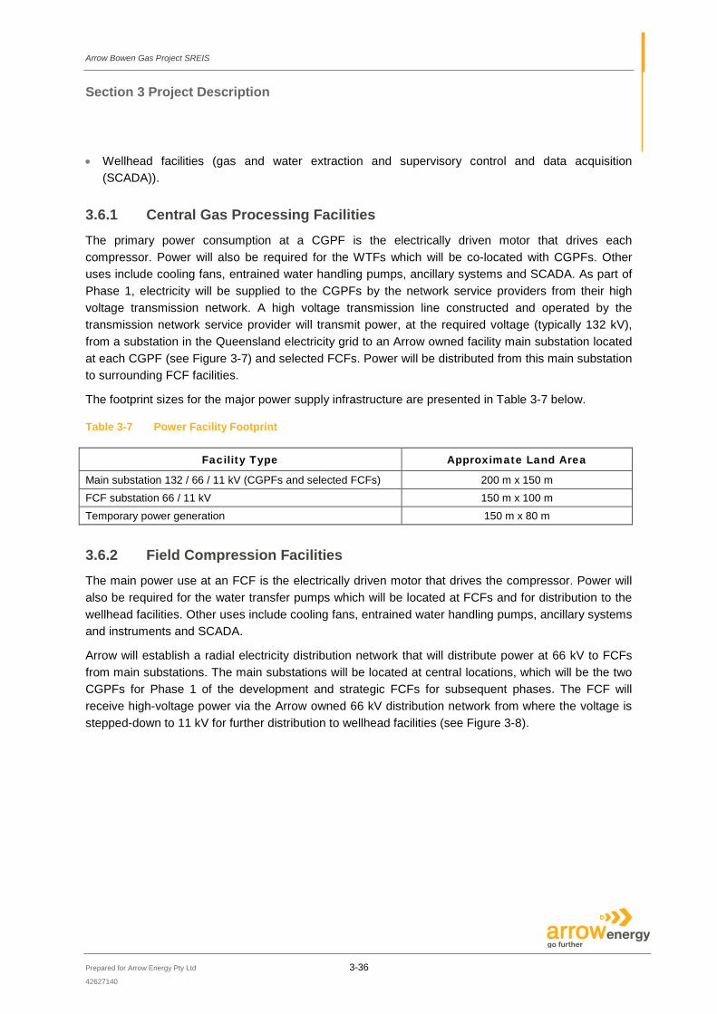
3.6.1 Central Gas Processing Facilities The primary power consumption at a CGPF is the electrically driven motor that drives each compressor. Power will also be required for the WTFs which will be co-located with CGPFs. Other uses include cooling fans, entrained water handling pumps, ancillary systems and SCADA. As part of Phase 1, electricity will be supplied to the CGPFs by the network service providers from their high voltage transmission network. A high voltage transmission line constructed and operated by the transmission network service provider will transmit power, at the required voltage (typically 132 kV), from a substation in the Queensland electricity grid to an Arrow owned facility main substation located at each CGPF (see Figure 3-7) and selected FCFs. Power will be distributed from this main substation to surrounding FCF facilities.
The footprint sizes for the major power supply infrastructure are presented in Table 3-7 below.
Table 3-7 Power Facility Footprint
Facility Type Approximate Land Area
Main substation 132 / 66 / 11 kV (CGPFs and selected FCFs) 200 m x 150 m FCF substation 66 / 11 kV 150 m x 100 m Temporary power generation 150 m x 80 m
3.6.2 Field Compression Facilities The main power use at an FCF is the electrically driven motor that drives the compressor. Power will also be required for the water transfer pumps which will be located at FCFs and for distribution to the wellhead facilities. Other uses include cooling fans, entrained water handling pumps, ancillary systems and instruments and SCADA.
Arrow will establish a radial electricity distribution network that will distribute power at 66 kV to FCFs from main substations. The main substations will be located at central locations, which will be the two CGPFs for Phase 1 of the development and strategic FCFs for subsequent phases. The FCF will receive high-voltage power via the Arrow owned 66 kV distribution network from where the voltage is stepped-down to 11 kV for further distribution to wellhead facilities (see Figure 3-8).
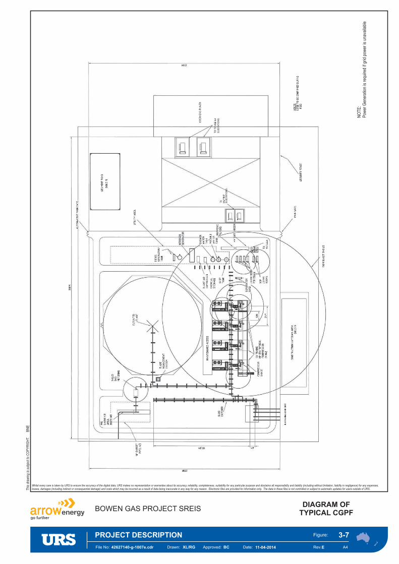
File No: Date:Approved:Drawn: Rev.
Figure:
A4
NO
TE
:P
ower
Gen
erat
ion
isre
quire
dif
grid
pow
eris
unav
aila
ble
SU
BSTA
TIO
NS
SU
BSTA
TIO
NS
42627140-g-1007e.cdr 11-04-2014BCXL/RG
DIAGRAM OFTYPICAL CGPF
E
PROJECT DESCRIPTION 3-7
BN
E
Whilst every care is taken by URS to ensure the accuracy of the digital data, URS makes no representation or warranties about its accuracy, reliability, completeness, suitability for any particular purpose and disclaims all responsibility and liability (including without limitation, liability in negligence) for any expenses,losses, damages (including indirect or consequential damage) and costs which may be incurred as a result of data being inaccurate in any way for any reason. Electronic files are provided for information only. The data in these files is not controlled or subject to automatic updates for users outside of URS.
BOWEN GAS PROJECT SREIS
Thi
sdr
awin
gis
subj
ect t
oC
OP
YR
IGH
T.
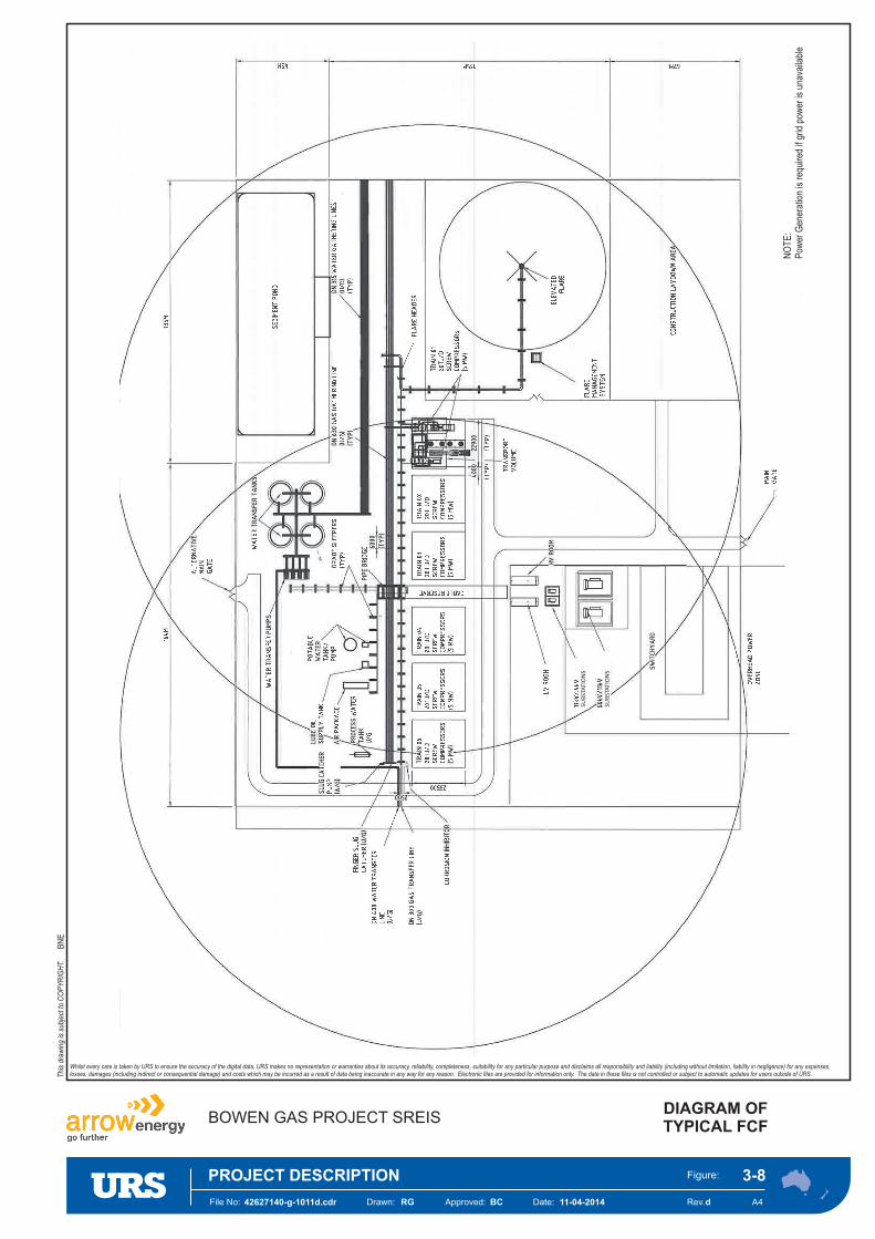
NO
TE
:P
ower
Gen
erat
ion
isre
quire
dif
grid
pow
eris
unav
aila
ble
SU
BSTA
TIO
NS
SU
BSTA
TIO
NS
File No: Date:Approved:Drawn: Rev.
Figure:
A442627140-g-1011d.cdr 11-04-2014BCRG
DIAGRAM OFTYPICAL FCF
d
PROJECT DESCRIPTION 3-8
BN
E
Whilst every care is taken by URS to ensure the accuracy of the digital data, URS makes no representation or warranties about its accuracy, reliability, completeness, suitability for any particular purpose and disclaims all responsibility and liability (including without limitation, liability in negligence) for any expenses,losses, damages (including indirect or consequential damage) and costs which may be incurred as a result of data being inaccurate in any way for any reason. Electronic files are provided for information only. The data in these files is not controlled or subject to automatic updates for users outside of URS.
BOWEN GAS PROJECT SREIS
Thi
sdr
awin
gis
subj
ect t
oC
OP
YR
IGH
T.
Arrow Bowen Gas Project SREIS
Section 3 Project Description
Prepared for Arrow Energy Pty Ltd 3-39
42627140
3.6.3 Wellhead Surface Facilities The key power users at the wellhead facility are a pump to remove water from the well and an instrument and SCADA system to transmit information from the wellhead to a central control room. Typically the power is distributed at 11 kV from the relevant FCF to the well or well pad site via an overhead line or underground cable as required, and preferably in the same easement as the gas and water gathering lines. A pole mounted or pad mounted 11 / 0.4 kV step down transformer would be located at each well pad with low voltage underground reticulation to provide power to each well.
The decision regarding if overhead / underground powerlines or on-site generation is to be used will depend on the land use and remoteness of the well location, which may be deemed more practical to install a local generator rather than reticulate.
In specific cases, power for remote wellheads may be generated on-site by gas fired engines during the Project life. It is proposed that up to 10% (400) of all wells may potentially be gas powered due to being unfeasible to connect to powerlines.
3.6.4 High Voltage Grid Connection and Power Distribution The SREIS case for supply of power is the supply of bulk electricity at 132 kV with the preferred option being to connect to existing transmission and / or distribution infrastructure in the Queensland electricity grid. Arrow will work with the Network Service Providers (NSP) to establish, suitable 132 kV connections at local substations in the vicinity of the major facilities to be developed in the Project area.
The electricity infrastructure connecting the main Arrow substations to the NSP substation will most likely be owned and operated by the NSP. This electricity transmission infrastructure providing the connection to the Queensland electricity grid will be subject to separate environmental approvals processes by the transmission NSP.
It is expected that the 132 kV connections from the NSP substation will consist of a fully redundant system to ensure adequate reliability of the power to the Arrow main substations which will be located at CGPFs for Phase 1 and strategic FCFs for Phase 2 onwards. The power to the main substations will be transmitted via double circuit overhead lines from the grid and will include a fibre optic ground wire for protection and communication systems.
Arrow will establish an electricity distribution network that will radially distribute electricity from the main facility substations to adjacent FCFs and subsequently to wellhead facilities and other infrastructure where it will power electric motors, lighting, air conditioning, supervisory control and data acquisition equipment as well as providing general purpose power. The electricity distribution to FCFs will be through 66 kV overhead powerlines and distribution to wellheads will be at 11 kV through overhead lines and where required underground power cables.
The new Arrow main substation and subsequent interconnected substations and distribution facilities will be focused in areas of the greatest gas resource and subsequent load concentration.
A diesel generator is required for power generation to supply critical services in the event of a power outage or other emergency situation at compression facilities and WTFs.
Arrow Bowen Gas Project SREIS
Section 3 Project Description
Prepared for Arrow Energy Pty Ltd 3-40
42627140
3.6.4.1 Transmission Lines
Due to the significant power requirements, overhead 132 kV transmission lines will connect the transmission network supply point substation, which are both owned and operated by the NSP to the facility main substation owned and operated by Arrow. In most cases an overhead 132 kV transmission line will connect the network substation to the facility main substation located within each CGPF for Phase 1 of the development and strategic FCFs for Phase 2 and onwards.
The transmission lines will comprise double circuits, with conductors suspended on steel lattice towers or guyed steel lattice towers or poles spaced at approximately 120 m to 400 m intervals depending on tower / pole type. Access tracks to and in some instances between the towers will be required to construct, inspect and maintain the transmission lines.
The alignment of transmission lines will be informed by physical, environment, social and landowner constraints. The type, spacing and height of towers / poles will be determined during the detailed design, where span lengths and tower / pole height will be optimised to reduce the number of tower / poles and achieve the required safety clearances to the ground, roads, structures and vegetation. Agricultural practices and equipment / infrastructure (i.e. irrigators) will be considered in the detailed design.
The typical easement width required for 132 kV overhead lines is 40 m to 60 m depending on the number of circuits. Vegetation on the easement will be cleared in accordance with the applicable electricity line safety clearance requirements. Typically, an access track of 6 m wide will be maintained along or adjacent to the centreline of the transmission line for operation and maintenance purposes. Where available, existing formed roads and tracks will be used to access transmission lines to ensure disturbance is minimised.
3.6.4.2 Facility Substations
The locations for the main substations will primarily be determined by the location of the compression facilities, the load and the proximity to the electricity supply network. The substation will consist of 132 kV switchgear with appropriate transformers for further sub distribution to the FCF as well as supply to the CGPF and WTF. The main substations will typically have a footprint of up to 200 m x 150 m.
The FCF substation will consist of 66 kV switchgear for further distribution to other FCFs as appropriate and transformers to provide power to the FCF associated facilities and wellhead facilities. The FCF substation will typically have a footprint of up to 150 m x 100 m.
Any other substations will form part of the compression and water facility design.
The facility substations will be owned by Arrow. The following equipment items form part of a main substation for connection to the grid:
• 132 / 66 / 11 kV transformer; • Air insulated switchgear; and • Control / protection building.
Arrow Bowen Gas Project SREIS
Section 3 Project Description
Prepared for Arrow Energy Pty Ltd 3-41
42627140
3.6.4.3 Distribution Lines
Power will be distributed from the Arrow main substations to the FCF substations. The size of these FCFs can vary and depends on the extracted gas flows.
Arrow will construct a power distribution network within the Project area consisting of 66 kV distribution lines to FCFs via an overhead reticulated power grid and 11 kV sub distribution from FCFs to wellheads via overhead or underground reticulated power. Arrow will own and operate the distribution powerlines required to provide power from the main substation to the associated production facilities. As far as possible, power distribution lines will be co-located with gathering and medium pressure pipelines.
Arrow proposes that the 66 kV overhead lines will consist of a double circuit line with composite insulators and fibre optic ground wire. The typical configuration will have a double circuit pole, vertical conductor configuration with line post insulation and fibre optic ground wire.
The typical easement width required for overhead lines (66 kV) will be 30 m to 50 m and the number of suspension poles versus strain poles will depend on the line route. The clearing along the line route will be minimised as far as possible and typically a 6 m cleared track with cut back of vegetation in the easement and 45 degree angle cut back of any encroaching vegetation is proposed. Where possible, it is proposed to utilise existing formed roads to access powerlines to minimise environmental disturbance.
The 11 kV overhead sub distribution system will typically consist of either steel or wood poles and will typically require an easement width of 20 m to 25 m depending on terrain and number of strain poles required. The clearing along the line route will be minimised as far as possible with cut back of vegetation in the easement.
3.6.5 Wellhead Power Supply The wellhead equipment for a single-well, comprising artificial lift system (pump) and other electrical equipment, requires approximately 20 kW of power on average (which means that the peak power requirement for a multi-well pad with up to 12 wells [6 vertical production conduits and 6 lateral wells] is approximately 120 kW, as only the vertical production conduits require power). Typically, the power is distributed at 11 kV from the relevant FCF to the well site via an overhead distribution line (preferred) or underground cable (as required) or where powerlines are not feasible then gas-fired engines driving electrical generators will be used. In some cases, it will be distributed directly from a third-party distribution substation and network via an 11 / 22 / 33 kV overhead transmission line.
In specific cases, power for remote wellheads will be generated on-site by gas fired engines during the Project life. It is proposed that 10% (400) of all wells will be gas powered due to the inability / unfeasibility to connect to powerlines.
3.6.6 Temporary Integrated Power Generation Integrated power generation was presented as the preferred option to supply power to the production facilities in the EIS, however; in this SREIS it is considered a temporary alternative if grid connection is not completed on time. Under this option, it is proposed to develop temporary power generation
Arrow Bowen Gas Project SREIS
Section 3 Project Description
Prepared for Arrow Energy Pty Ltd 3-42
42627140
(electrical power) utilising CSG as a fuel source at selected CGPFs and FCFs as required. This will only be the case for facilities (i.e. CGPFs, WTFs and FCFs) constructed in Phase 1 and only potentially for approximately 2 years of the initial Project development.
The decision on power generation will focus on power generation equipment which uses high efficiency low emission reciprocating gas engines or other high efficiency technology options offering competitive high efficiency power generation.
The assumed base case is that the expected ranges of power (see Table 3–2) could be generated by reciprocating gas engines with lean burn technology to achieve a good efficiency with reduced emissions (low NOx combustion technology).
3.6.6.1 Description and Layout
The function of the temporary integrated power generation facility is to generate electrical power from the combustion of CSG through a series of gas fired reciprocating engines and related electrical generators and substation equipment.
The CSG from the adjacent gas field will be metered and the saturated water in the gas stripped to meet the required specifications for combustion in the gas engines.
The gas processing facility temporary load requirements, the size of the power generation facility, the selected size of each generator and the required redundancy (normally expected to be one engine) will determine the total number of generators required for each facility.
Each engine is coupled to an alternator generating power to the facility. The individual generating sets will each have its own exhaust silencer stack with an anticipated height of seven metres and housed in an acoustic enclosure, complete with fire and gas detection and associated shutdowns. The electrical output from each generating set is taken to switchgear from where it is distributed to the compression equipment, water treatment and other facilities and equipment as appropriate.
The facility will also contain on-site workshop and office facilities and a combined control room / switch room.
On-site lubricating oil storage for both clean and used oil will be provided within an appropriately contained storage and pumping facility. All other waste liquids from the operation of the facility will be contained and stored on-site in tanks, with periodic pump-out by road tanker for off-site disposal / recycling at approved sites.
Potable water reticulation will be supplied from on-site water tanks, collecting rainwater runoff from the selected roofs. Additional water can be imported via tanker if required.
A preliminary area of 80 m x 150 m has been estimated as a sufficient footprint to accommodate the power generation facility, if required, which will be located next to the facility substation for connection to the grid if appropriate.
Electrical power may also be distributed to the adjacent facilities via the facilities power distribution network. The distribution may be delivered by overhead line or underground cable and may be one of either method for a specific facility. This decision will be determined during the FEED / design phase.

Arrow Bowen Gas Project SREIS
Section 3 Project Description
Prepared for Arrow Energy Pty Ltd 3-43
42627140
3.6.6.2 Major Equipment Items
The following major equipment items will be installed at the temporary integrated power generation facility, if required:
• Gas engine generating sets; • Gas metering facilities; • Gas treatment facilities; • Oil storage facilities; • 11 kV switchgear; • Controls / switchroom; and • Auxiliaries.
3.7 Changes to Construction Techniques Construction activities for the Project will essentially occur over the expected 35-40 year Project life (including early works) at a rate that aligns with the gas production requirements. Currently, approximately 4,000 production wells, 33 FCFs, 2 CGPFs and 2 WTFs (with a third WTF potentially being built in the Blackwater region in later stages of the Project) are expected to be constructed across the approximate 8,000 km2 Project area.
3.7.1 CGPF – Flaring Scenario In an effort to reduce gas flaring and therefore unwanted air emissions, Arrow is planning to minimise flaring associated with the Upstream Project ramp-up from the design case for the Project (as opposed to what was presented in the EIS). Based on the timing of the Surat Gas Project (with the first Arrow LNG Train) and the Arrow Bowen Pipeline Project, the Bowen Gas Project commissioning strategy looks to utilise gas from the Arrow Bowen Pipeline, backfilled from the Gladstone Gas Hub, for commissioning of the CGPFs. This negates the need to use gas from Bowen wells for commissioning of the CGPFs and minimises the possibility of excess gas being flared during commissioning of the upstream facilities (see Figure 3-9).
3.7.2 Production Wells – Well Site Completions A completion rig is typically used post drilling to install the artificial lift system (downhole pump) and prepare the wellbore for production. The completions rig comprises of a number of units that make up the rig itself with a complement of site offices, equipment and stores. During completions and well intervention operations, additional large vehicles are required to enter and leave site to support operations. The equipment and mobility requirements are used to determine the footprint of the rig.
The overall size and shape of completions rigs varies from manufacturer to manufacturer and capacity and functionality of the rig. For well interventions, the rig size required may be driven by the type of well intervention required and the availability of rigs to execute the operation.
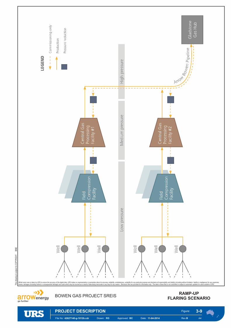
File No: Date:Approved:Drawn: Rev.
Figure:
A442627140-g-1012b.cdr 11-04-2014BCRG
RAMP-UPFLARING SCENARIO
B
PROJECT DESCRIPTION 3-9
BN
E
Whilst every care is taken by URS to ensure the accuracy of the digital data, URS makes no representation or warranties about its accuracy, reliability, completeness, suitability for any particular purpose and disclaims all responsibility and liability (including without limitation, liability in negligence) for any expenses,losses, damages (including indirect or consequential damage) and costs which may be incurred as a result of data being inaccurate in any way for any reason. Electronic files are provided for information only. The data in these files is not controlled or subject to automatic updates for users outside of URS.
BOWEN GAS PROJECT SREIS
Thi
sdr
awin
gis
subj
ect t
oC
OP
YR
IGH
T.
Arrow Bowen Gas Project SREIS
Section 3 Project Description
Prepared for Arrow Energy Pty Ltd 3-45
42627140
The artificial lift system installed in the well by the completions rig typically consists of a subsurface downhole pump either driven at surface or subsurface by electrical power. The downhole pump pumps water found in the coal seams to surface through tubing installed in the well, reducing the hydrostatic pressure head on the coal seam. The reduction in pressure allows the methane gas in the coal seam to be released into the well bore.
The footprint of a completions rig is generally smaller than a drilling rig, however, as production facilities are in place, the pad design needs to facilitate working around production equipment and provide suitable access and equipment isolations. The same requirements exist for both initial completions and ongoing well intervention operations.
3.7.3 Gas and Water Gathering Systems – Gathering Line Installation The depth of pipeline burial will conform to regulations as a minimum but will ultimately depend on the existing condition. The pipeline depth will be 750 mm to 1,200 mm, however; it may be greater in specific areas, such as railways, state or third party controlled roads, and major watercourse crossings. Furthermore, landowners will be consulted to determine land use practices, such as cultivation, and pipelines will be buried to a depth that minimises impact on landholders and risk of damage.
The two main construction methods of gathering line installation are conventional trenching and plough-in. There will be locations where neither method is suitable (e.g. due to river or road crossings and other potential environmental constraints) and other design options in these cases are horizontal directional drilling and horizontal boring.
Use of the plough-in strategy (it is anticipated that ploughing may be appropriate for 30% to 45% of the pipeline routes) will reduce ground disturbance and minimise the amount of restoration required after the gathering system is installed. This will result in minimising the Project’s environmental impact because ploughing requires a narrower right-of-way (ROW) so land disturbance is less than when trenching. Plough-in technology will therefore be used as a preference whenever possible.
3.7.3.1 Trenching
Trenching involves excavating a trench, installing the pipe and backfilling as separate activities. Trenching can be used for all the pipe sizes that are included in the Project.
Gas and water gathering pipelines will be installed and buried in the same trench. This will minimize the amount of surface land disturbance. Top and sub-soil will be stockpiled on the ROW for backfilling and surface rehabilitation.
The length of exposed trench will be minimised during construction. Where required, breaks in the trench will be installed to facilitate stock and wildlife crossings.
The pipe will be lowered into the trench using side-boom or all-terrain vehicles. Other equipment used to trench and lay pipelines include graders, excavators, tip trucks, low loaders, ploughs, trenchers, backhoes, fuel delivery trucks and four-wheel drive coaster buses.
Arrow Bowen Gas Project SREIS
Section 3 Project Description
Prepared for Arrow Energy Pty Ltd 3-46
42627140
3.7.3.2 Plough-in
By utilising plough-in technology, the pipeline is generally installed in a single operation using specialist equipment where no open trench is involved, however; note that pre-trenching can sometimes be required for plough-in The application of plough-in techniques is limited by pipe size and geotechnical constraints. The plough-in technique can be used where the ground conditions are suitable and for pipes up to 450 mm diameter for a single pipe or 315 mm diameter for twin pipes.
3.7.4 Transmission Lines and Network Service Provider Substations High voltage transmission lines and NSP substations, where required, will be designed and constructed by the transmission network service provider in accordance with relevant electricity supply, design and safety standards, and typical construction methods.
3.7.5 Distribution Network Substations at the CGPFs, FCFs and overhead power lines comprising poles and insulators supporting conductors will be designed and constructed in accordance with relevant electricity design and safety standards, and typical construction methods.
The 66 kV overhead distribution lines to the FCFs will be installed in the same ROW as the medium-pressure gas pipelines whenever possible and the 11 kV overhead or underground sub distribution to the wells will be installed in the same ROW as the gas and water gathering pipelines whenever possible. Where underground cables are installed, similar methods employed for the installation of gas and water gathering systems, in accordance with relevant electricity design and safety standards, will be used.
3.7.6 Pipeline Crossing Construction Methods Depending on the nature of the crossing, the types of construction outlined below may be used.
3.7.6.1 Open Cut
Open-cut methods are used to cross selected waterways and roads. In this method, a trench is excavated using a trenching machine or an excavator. Open-cut construction involves the continuation of normal pipeline trench construction methods through the waterway or road. Trench material is placed adjacent to the road or on each waterway bank. Crossings are open for the minimum amount of time to limit disruption of stream flows or vehicle traffic.
Open-cut waterway crossings are most suited to ephemeral or low-flow waterways. Typically, flows are maintained during open-cut construction; however, for waterways with high flow rates or volumes, flow diversion may be required. Flow diversion can be achieved prior to pipeline construction by the installation of flumes, pumping of water around the worksite or cofferdams. Cofferdams would be constructed using very large sandbags, water filled bladders or steel sheet piles to divert flow around the worksite. Typically, only half of a major watercourse is diverted at a time.
Arrow Bowen Gas Project SREIS
Section 3 Project Description
Prepared for Arrow Energy Pty Ltd 3-47
42627140
Open-cut methods may be used for watercourse crossings where rapid construction is considered the best means of minimising environmental impact (APIA, 2009).
Machinery will cross waterways in a manner that minimises further disturbance. Sediment control measures will be implemented to minimise sediment transport and construction methods will minimise riverbed scouring.
3.7.6.2 Horizontal Directional Drilling
This method is used to drill under large waterways, large roads and, where necessary, railway lines. The aim is to reduce above-ground environmental impacts and reduce disruption to vehicle traffic or train movements. This method involves drilling a curved hole at a shallow angle under the feature, through which the pipe is pulled or pushed. Once a pilot hole is established, it is then reamed or enlarged to approximately 1.25 times the diameter of the pipe. The borehole may be cased or uncased depending on the geology of the area. The pipe is then pulled through the casing or borehole.
3.7.6.3 Horizontal Boring
Boring involves the usually horizontal drilling of a short borehole to install pipelines beneath larger roads, railway lines and buried utilities. In order to drill the borehole, bore pits are constructed within the ROW on both sides of the road, railway line or utility. A thrust bore drilling rig is placed in the pit to drill a hole that is typically 10 m long by up to 4 m in diameter. Bored crossings are limited by the depth, width and length of crossing, geology and presence of groundwater. Small amounts of shallow groundwater can be temporarily drained from the work area during construction.
Boring significantly reduces environmental impacts and does not disrupt traffic flows.
3.7.7 Construction Materials
3.7.7.1 Aggregate
The vast majority of the aggregate requirements for the Project are associated with the well pads and roads (approximately 99%). Arrow has assumed, as a worst case scenario, that for the CGPFs, WTFs and FCFs the only requirements will be for aggregate on the roadways. These areas would likely be treated with polymers to avoid using aggregates, however; Arrow is waiting on the conclusions from trials being conducted for the Surat Gas Project. For the roads, Arrow has used an average length of 800 m, a width of 3 m to 6 m and a depth of 300 mm. These are indicative and may be amended at a later stage as more information is known in regards to the geotechnical aspects of the areas, the topography, and the precise finish which is applied to them.
Arrow is expecting up to 5 million tonnes of gravel to be required across the Project area for the life of the Project.
Arrow Bowen Gas Project SREIS
Section 3 Project Description
Prepared for Arrow Energy Pty Ltd 3-48
42627140
3.7.7.2 Construction Water
The proposed approach for the Project SREIS is that where possible Arrow will source as much of the required construction water as possible from Arrow stocks of CSG production water. The following is what is currently proposed for the Project:
• An initial peak requirement of approximately 175 ML per year for the first 2 years (assuming Arrow build the 2x CGPFs, 16x FCFs, 2x WTFs (with associated dams and roads)), and a further 10 ML allowed for dust suppression and access roads; and
• An average of approximately 10 ML per year for the remaining life of the Project.
3.8 Operations and Maintenance Changes Control of the production facilities will be managed centrally from the Brisbane Central Control Room on a 24 hour / 7 day full time basis. The facilities will therefore incorporate a high level of monitoring, automation and communications.
Not Normally Manned (NNM) operations are defined as those operations where operations staff are not permanently allocated to a specific facility, but allocated across a number of facilities and visit a facility on an as needed basis for a specific purpose. The NNM philosophy is the long term operations intention for the Project, and will be implemented when commissioning has been completed and reliable steady state operations has been proven.
NNM facilities will require periodic visits (e.g. fortnightly for operators and quarterly for maintenance) to carry out inspections or other scheduled routine work activities.
The introduction of the NNM concept is related to and associated with the “operations” of the CGPFs, FCFs, WTFs, wellheads, and gathering system.
Due to travel distances and times between the CGPFs and Moranbah it is proposed that the North Maintenance base be co-located with the North Central Operating Base (COB) (which is adjacent to CGPF1) to serve CGPF1, associated FCFs, wells and gathering system and the WTF1.
Similarly the South Maintenance base will be co-located with the South COB to serve CGPF2, associated FCFs, wells and gathering system and the WTF2.
Hence in the NNM philosophy all operators are allocated to a specific COB with its associated gas drainage areas. COBs provide an office facility incorporating a Facility Control Consul, Permit to Work office, meeting room with video conferencing capability, consumables store and basic workshop facility, first aid facility, emergency response facility and required utilities for all personnel (e.g. potable water, data and communications connectivity, toilets, and waste management).
The main centralised warehouse and workshop for the Project operations will be located at Moranbah.
Each COB will have a small store facility to carry routine consumables stock only. Remaining operations and maintenance spares will be stocked and managed from Moranbah centralised warehouse.
Arrow Bowen Gas Project SREIS
Section 3 Project Description
Prepared for Arrow Energy Pty Ltd 3-49
42627140
3.8.1 Production Wells – Inspections and Monitoring The production wellhead sites will normally be unmanned and only visited by the well field operator or maintenance personnel according to pre-set schedules, e.g. for sampling, thermography, vibration analysis of auxiliary equipment, visual condition monitoring and gas leak detection. Production wells will be remotely operated and monitored for gas and water flow rates and gas pressure from the central control room. The well visit frequency will ensure that legislative requirements are met.
3.8.2 Well Workovers A completion rig is typically used post initial well completion to perform well intervention activities, also known as workovers. Workovers are used to repair or optimise the well and to maintain the wellbore integrity (for example, repairing the artificial lift system by removing and replacing the pump).
An average pump run life of two years is expected over the course of the Project, which Arrow will endeavour to maximise through technology improvements. Individual wells will show a variation around the average run life. This results from differences in geology (e.g. the amount of solids that may be drawn through the pump) and in the loads placed on the well pump system due to different well shapes (for lateral wells). For multi-well pads, this does mean that a workover rig will be in attendance at the pad proportionately more often than if there was a single well. This is offset in terms of overall footprint by requiring fewer surface locations for multi-well pads.
3.8.3 Gas Processing Facilities CGPFs and FCFs will be fully automated and designed for minimal operator intervention. They will be controlled and their integrity remotely monitored by a computer-based integrated control system that includes process and safety controls. Operators are notified through warnings and alarms of changes in key operating parameters.
Typical operations and maintenance tasks at the CGPFs and FCFs will include:
• Operations:
— Routine Visual Inspection; — First Line Maintenance or Autonomous Care (cleaning, lubrication, filters, etc.); and — Monitoring activities;
• Maintenance:
— Oil Sampling; — Offline Vibration Monitoring; and — Repairs.
Equipment that requires major maintenance work will be removed to the centralised maintenance depots and from there to a sub-contractor.
It is expected that major compressor inspection and maintenance will be required every 3 – 5 years.
Arrow Bowen Gas Project SREIS
Section 3 Project Description
Prepared for Arrow Energy Pty Ltd 3-50
42627140
3.8.4 Water Treatment Facilities For operational purposes the WTFs include their associated dams (including the brine dam), and transfer stations.
The WTF will be operated 24 hours a day, 7 days a week.
WTFs will be fully automated and designed for minimal operator intervention. They will be controlled and their integrity remotely monitored by a computer-based integrated control system that includes process and safety controls. Operators are notified through warnings and alarms of changes in key operating parameters.
Typical operation and maintenance tasks at the WTFs will include:
• Routine visual inspection; • First Line Maintenance or Autonomous Care (cleaning, lubrication, filters, etc.); • Chemical delivery; • Solid waste disposal; • Monitoring and sampling activities; and • Emergency repairs as necessary.
Regular maintenance activities to maintain plant performance include backwash, regeneration and clean in place and are done using automated systems.
Major maintenance (outages / overhauls) will be undertaken in accordance with manufacturer specifications and based on condition monitoring and exception based surveillance:
• Microfiltration (MF) / ultrafiltratrion (UF) membranes every 5 to 10 years; and • Reverse Oosmosis membranes every 3 to 5 years.
3.8.5 SCADA and Communications The HSBN will interconnect the FCFs and CGPFs as well as extending into the well fields.
The HSBN will include buried fibre optic cables and microwave radio links. The fibre optic cables will be placed in the same easement as the low pressure gas gathering pipelines and medium pressure infield pipelines.
Arrow communications tower specifications are for long term free standing towers and meet CAA guidelines. Depending on the geography they range in height from 65 m to 100 m conceptually. Dimensions vary with the size of the tower and the geological reports of the location for installation. An average tower can fit on a space 10 m x 10 m.
Arrow will always look for hills to install towers, as this means a smaller tower is required; hilltops are also often rocky and therefore not cropped ground. Arrow towers which are not located with facilities would be solar powered and have remote monitoring, closed-circuit television, proximity and security systems installed. Arrow has estimated the need to install around four towers.
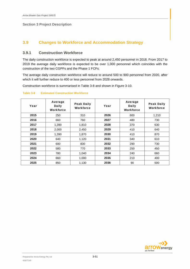
Arrow Bowen Gas Project SREIS
Section 3 Project Description
Prepared for Arrow Energy Pty Ltd 3-51
42627140
3.9 Changes to Workforce and Accommodation Strategy
3.9.1 Construction Workforce The daily construction workforce is expected to peak at around 2,450 personnel in 2018. From 2017 to 2019 the average daily workforce is expected to be over 1,000 personnel which coincides with the construction of the two CGPFs and the Phase 1 FCFs.
The average daily construction workforce will reduce to around 500 to 900 personnel from 2020, after which it will further reduce to 400 or less personnel from 2028 onwards.
Construction workforce is summarised in Table 3-8 and shown in Figure 3-10.
Table 3-8 Estimated Construction Workforce
Year Average
Daily Workforce
Peak Daily Workforce
Year Average
Daily Workforce
Peak Daily Workforce
2015 250 310 2026 600 1,210 2016 660 760 2027 480 730 2017 1,390 1,810 2028 370 630 2018 2,000 2,450 2029 410 640 2019 1,390 1,870 2030 410 870 2020 640 1,120 2031 340 610 2021 600 830 2032 290 730 2022 580 770 2033 250 450 2023 780 1,040 2034 240 660 2024 660 1,000 2035 210 400 2025 850 1,130 2036 90 500

Arrow Bowen Gas Project SREIS
Section 3 Project Description
Prepared for Arrow Energy Pty Ltd 3-52
42627140
Figure 3-10 Peak and Average Daily Construction Workforce
The predominant construction workforce roles will include the following functions:
• Direct construction labour required to construct all infrastructure; • Direct construction management calculated as a percentage (15%) of the direct labour
requirement; and • Well and gathering system installation and commissioning personnel including:
— Well site preparation; — Well drilling and completions (i.e. the completion of the subsurface aspects of the well and the
deployment of down-hole equipment); — Surface equipment installation; — Connection of wells to gathering systems; — Installation of low-pressure gas pipelines and water gathering systems and infield medium-
pressure gas pipelines; and — Testing and commissioning.
The make-up of the estimated construction workforce roles are outlined in Table 3-9.
0
500
1000
1500
2000
2500
3000
2015
2016
2017
2018
2019
2020
2021
2022
2023
2024
2025
2026
2027
2028
2029
2030
2031
2032
2033
2034
2035
2036
Man
-Pow
er
Year
Average
Peak
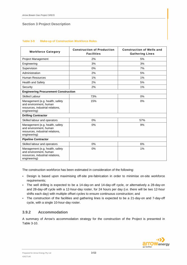
Arrow Bowen Gas Project SREIS
Section 3 Project Description
Prepared for Arrow Energy Pty Ltd 3-53
42627140
Table 3-9 Make-up of Construction Workforce Roles
Workforce Category Construction of Production
Facilities Construction of Wells and
Gathering Lines
Project Management 2% 5% Engineering 3% 3% Supervision 0% 7% Administration 2% 5% Human Resources 1% 1% Health and Safety 2% 5% Security 2% 1% Engineering Procurement Construction Skilled Labour 73% 0% Management (e.g. health, safety and environment, human resources, industrial relations, engineering)
15% 0%
Drilling Contractor Skilled labour and operators 0% 57% Management (e.g. health, safety and environment, human resources, industrial relations, engineering)
0% 9%
Pipeline Contractor Skilled labour and operators 0% 6% Management (e.g. health, safety and environment, human resources, industrial relations, engineering)
0% 1%
The construction workforce has been estimated in consideration of the following:
• Design is based upon maximising off-site pre-fabrication in order to minimise on-site workforce requirements;
• The well drilling is expected to be a 14-day-on and 14-day-off cycle, or alternatively a 28-day-on and 28-day-off cycle with a 12-hour-day roster, for 24 hours per day (i.e. there will be two 12-hour shifts each day) with multiple offset cycles to ensure continuous construction; and
• The construction of the facilities and gathering lines is expected to be a 21-day-on and 7-day-off cycle, with a single 10-hour-day roster.
3.9.2 Accommodation A summary of Arrow’s accommodation strategy for the construction of the Project is presented in Table 3-10.

Arrow Bowen Gas Project SREIS
Section 3 Project Description
Prepared for Arrow Energy Pty Ltd 3-54
42627140
Table 3-10 Accommodation Strategy
Accommodation Aspect
Strategy
Site Selection It is currently envisaged that purpose-built accommodation will be constructed as follows: • Two main villages located near CGPF1 and CGPF2, designed and built as
permanent accommodation solutions to house the construction workforce as well as long term permanent staff expected to be fly-in / fly-out (FIFO) (including workover crews).
• In addition, and in an effort to minimise staff travelling time, several smaller temporary villages (currently estimated to be another four) are expected to be required when the facilities associated with the drainage areas furthest away from the CGPFs are under construction. Temporary accommodation will also be utilised in the early stages of the Project (i.e. 2015 – 2016) until the permanent accommodation has been constructed.
Site selection will pay due regard to the following factors: • Achieving a max commuting time of approximately 30 minutes to the work fronts; • Design; • Environmental constraints; • Social constraints; • Cultural heritage constraints; • Native title sensitivities; and • Avoidance of strategic cropping land.
Village Size The final size and number of accommodation villages will be influenced by: • The rate of Project development; • The distance between nearby gas processing facility sites; • Opportunities for efficient use (or reuse) of accommodation infrastructure and
resources; and • The level of overlapping between temporary construction workforce and permanent
staff. Accommodation villages will be sized to accommodate: • 100% of the peak construction workforce; • 100% well and gathering line installation construction team; and • 100% of permanent FIFO operations staff.
Village Facilities Accommodation villages are designed to be self-sufficient for power, water and sewage services, and will include: • Individual sleeping quarters; • Catering services, commercial kitchen and dining area; • Recreation facilities; • Ensuite facilities; • Laundry facilities; • First aid; • Vehicle parking; and • Security fence. Onsite couple and family accommodation is not anticipated.

Arrow Bowen Gas Project SREIS
Section 3 Project Description
Prepared for Arrow Energy Pty Ltd 3-55
42627140
Accommodation Aspect
Strategy
Establishment Accommodation villages will be modular in design to enable them to expand and contract in line with the requirements. The ‘pioneer’ workforce required to establish accommodation villages will be housed in existing accommodation camps in the area until sufficient units are constructed.
Short-term Accommodation
In addition to the construction workforce, Arrow anticipates a constant stream (average of 20 persons, 5 days a week) of management personnel and specialist consultants who may visit the Project development area. Where possible, these personnel will be accommodated in accommodation villages. However, during peak activities, it is likely these personnel will seek motel or similar accommodation in nearby towns.
The long-term nature of the Project requires that the facilities provide accommodation for a wide range of workforce disciplines and skills from many companies.
Small mobile camps to house drilling and completions staff may also be required in a location central to the drilling activities. These camps would contain a small canteen, vehicle parking areas and waste collection and storage areas. Dedicated staff will be responsible for managing the accommodation facilities.
These temporary workers accommodation facilities will typically occupy an area of around 500 m by 500 m.
3.9.3 Permanent Workforce Approximately 250 to 300 permanent operations and maintenance personnel will be required for the Project in the operations, maintenance, support and administration teams (this excludes Arrow Brisbane based staff, workover crew and field maintenance contractors). This peak is expected to be reached by 2028 and remain at plateau for approximately 13 years before declining as the gas reserves are depleted.
The workover crews (which include the well completion crews based on the same rigs being used) are expected to range between 10 and 100 people over the life of the proposed development (averaging at around 65 personnel onsite at any given time).
Arrow’s order of preference for operations and maintenance workforce sourcing is as presented in the EIS:
• Local area (lives within the study area); • Regional (lives within southern or central Queensland); • National (lives in Australia); and • International (lives outside Australia).
Despite the preference to source workforce from the local area, the expectation is that the majority of the operations and maintenance personnel will be FIFO, dependant on the availability of a select skilled workforce base in the area.

Arrow Bowen Gas Project SREIS
Section 3 Project Description
Prepared for Arrow Energy Pty Ltd 3-56
42627140
3.9.4 Operations Accommodation The proportion of the permanent workforce that will be sourced locally are assumed to have existing accommodation in the local area. Operations and maintenance personnel expected to be sourced from outside of the Project area, will be accommodated in villages co-located with the COBs. Due to the reduction in operational workforce numbers since the publication of the EIS (i.e. 600 to 300 operational staff), Arrow have a target split going forward of 20% local and 80% FIFO, in comparison to the 10% / 90% split presented in the EIS.


