arris.com Optical Passives and AccessoriesThe OS1000 is a 4‐rack unit (4RU) telecommunications...
17
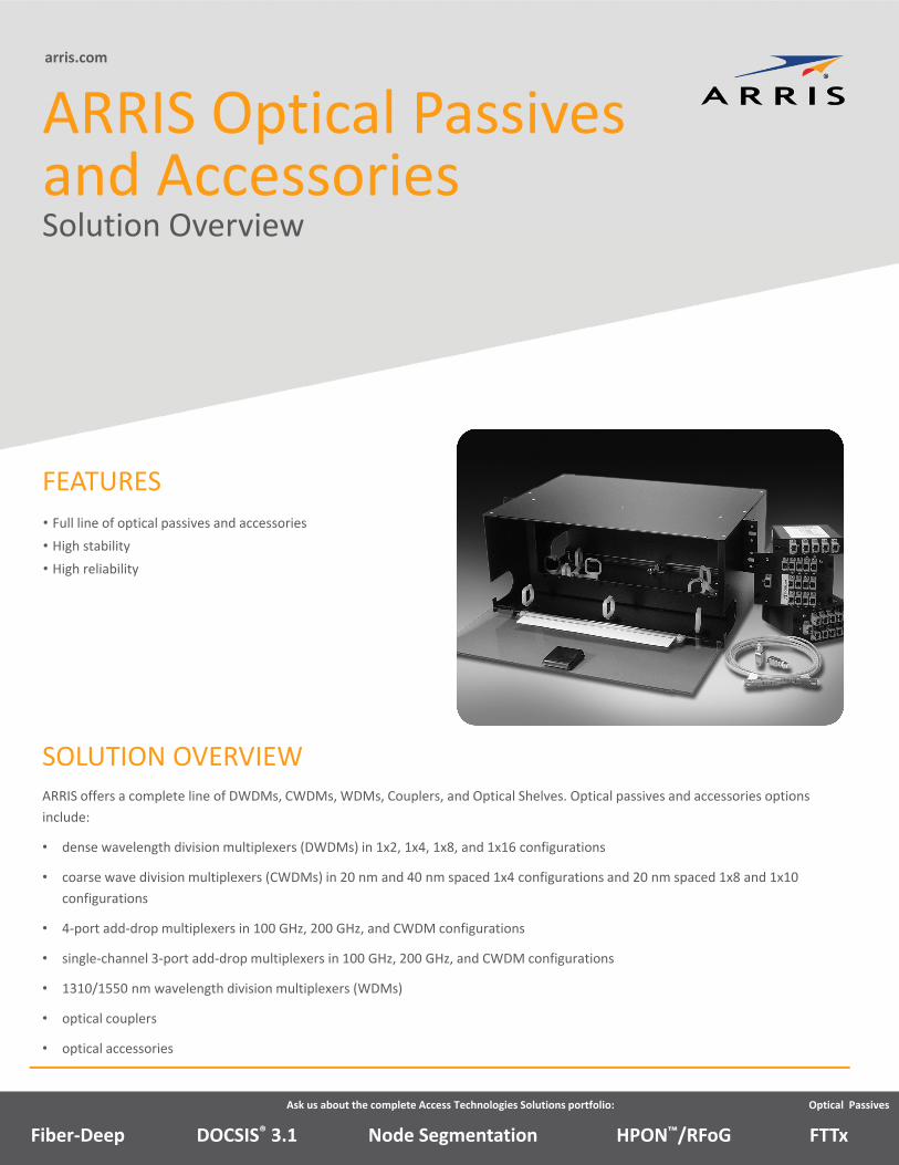
arris.com • Full line of optical passives and accessories • High stability • High reliability ARRIS Optical Passives and Accessories Solution Overview ARRIS offers a complete line of DWDMs, CWDMs, WDMs, Couplers, and Optical Shelves. Optical passives and accessories options include: • dense wavelength division multiplexers (DWDMs) in 1x2, 1x4, 1x8, and 1x16 configurations • coarse wave division multiplexers (CWDMs) in 20 nm and 40 nm spaced 1x4 configurations and 20 nm spaced 1x8 and 1x10 configurations • 4‐port add‐drop multiplexers in 100 GHz, 200 GHz, and CWDM configurations • single‐channel 3‐port add‐drop multiplexers in 100 GHz, 200 GHz, and CWDM configurations • 1310/1550 nm wavelength division multiplexers (WDMs) • optical couplers • optical accessories SOLUTION OVERVIEW FEATURES Ask us about the complete Access Technologies Solutions portfolio: Node Segmentation DOCSIS ® 3.1 Fiber‐Deep HPON ™ /RFoG FTTx Optical Passives
Transcript of arris.com Optical Passives and AccessoriesThe OS1000 is a 4‐rack unit (4RU) telecommunications...
arris.com
• Full line of optical passives and accessories
• High stability
• High reliability
ARRIS Optical Passives and AccessoriesSolution Overview
ARRIS offers a complete line of DWDMs, CWDMs, WDMs, Couplers, and Optical Shelves. Optical passives and accessories options
include:
• dense wavelength division multiplexers (DWDMs) in 1x2, 1x4, 1x8, and 1x16 configurations
• coarse wave division multiplexers (CWDMs) in 20 nm and 40 nm spaced 1x4 configurations and 20 nm spaced 1x8 and 1x10
configurations
• 4‐port add‐drop multiplexers in 100 GHz, 200 GHz, and CWDM configurations
• single‐channel 3‐port add‐drop multiplexers in 100 GHz, 200 GHz, and CWDM configurations
• 1310/1550 nm wavelength division multiplexers (WDMs)
• optical couplers
• optical accessories
SOLUTION OVERVIEW
FEATURES
Ask us about the complete Access Technologies Solutions portfolio:
Node SegmentationDOCSIS® 3.1Fiber‐Deep HPON™/RFoG FTTx
Optical Passives
ARRIS Optical Passives and Accessories
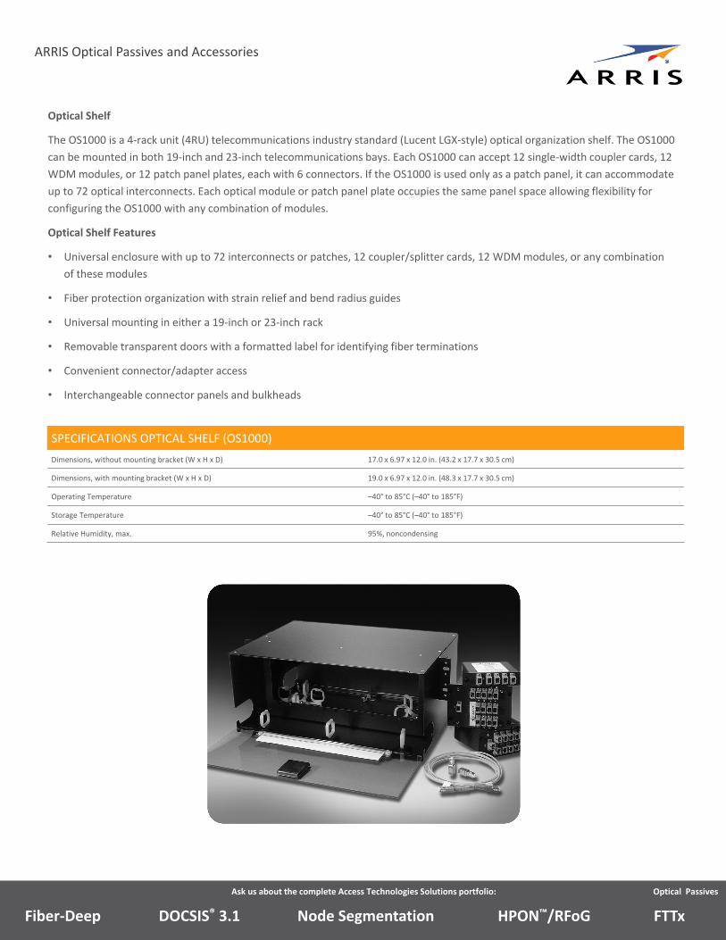
Optical Shelf
The OS1000 is a 4‐rack unit (4RU) telecommunications industry standard (Lucent LGX‐style) optical organization shelf. The OS1000
can be mounted in both 19‐inch and 23‐inch telecommunications bays. Each OS1000 can accept 12 single‐width coupler cards, 12
WDM modules, or 12 patch panel plates, each with 6 connectors. If the OS1000 is used only as a patch panel, it can accommodate
up to 72 optical interconnects. Each optical module or patch panel plate occupies the same panel space allowing flexibility for
configuring the OS1000 with any combination of modules.
Optical Shelf Features
• Universal enclosure with up to 72 interconnects or patches, 12 coupler/splitter cards, 12 WDM modules, or any combination
of these modules
• Fiber protection organization with strain relief and bend radius guides
• Universal mounting in either a 19‐inch or 23‐inch rack
• Removable transparent doors with a formatted label for identifying fiber terminations
• Convenient connector/adapter access
• Interchangeable connector panels and bulkheads
Ask us about the complete Access Technologies Solutions portfolio:
SPECIFICATIONS OPTICAL SHELF (OS1000)
Dimensions, without mounting bracket (W x H x D) 17.0 x 6.97 x 12.0 in. (43.2 x 17.7 x 30.5 cm)
Dimensions, with mounting bracket (W x H x D) 19.0 x 6.97 x 12.0 in. (48.3 x 17.7 x 30.5 cm)
Operating Temperature –40° to 85°C (–40° to 185°F)
Storage Temperature –40° to 85°C (–40° to 185°F)
Relative Humidity, max. 95%, noncondensing
Node SegmentationDOCSIS® 3.1Fiber‐Deep HPON™/RFoG FTTx
Optical Passives
ARRIS Optical Passives and Accessories
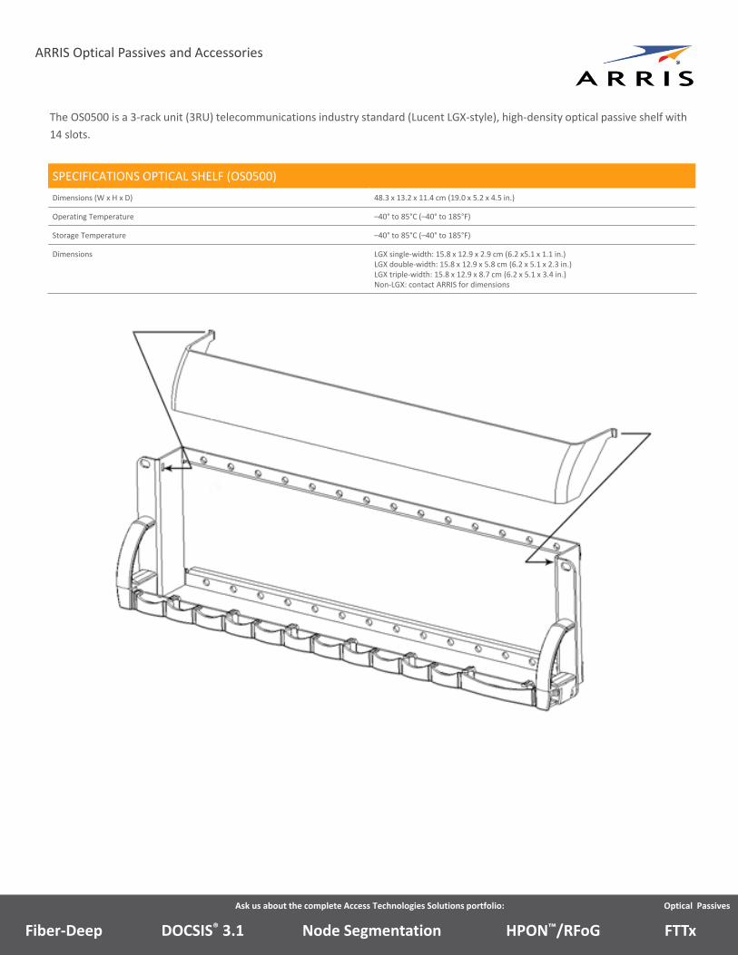
The OS0500 is a 3‐rack unit (3RU) telecommunications industry standard (Lucent LGX‐style), high‐density optical passive shelf with
14 slots.
Ask us about the complete Access Technologies Solutions portfolio: Optical Passives
Node SegmentationDOCSIS® 3.1Fiber‐Deep HPON™/RFoG FTTx
SPECIFICATIONS OPTICAL SHELF (OS0500)
Dimensions (W x H x D) 48.3 x 13.2 x 11.4 cm (19.0 x 5.2 x 4.5 in.)
Operating Temperature –40° to 85°C (–40° to 185°F)
Storage Temperature –40° to 85°C (–40° to 185°F)
Dimensions LGX single‐width: 15.8 x 12.9 x 2.9 cm (6.2 x5.1 x 1.1 in.)LGX double‐width: 15.8 x 12.9 x 5.8 cm (6.2 x 5.1 x 2.3 in.)LGX triple‐width: 15.8 x 12.9 x 8.7 cm (6.2 x 5.1 x 3.4 in.)Non‐LGX: contact ARRIS for dimensions
ARRIS Optical Passives and Accessories
DWDM/CWDM Modules
ARRIS DWDMs/CWDMs enable simultaneous transmission of optical signals at multiple wavelengths on one fiber. The
wavelengths are located in the CWDM region (1430 to 1620 nm) or the DWDM region (1528 to 1563 nm). DWDMs/CWDMs can
be used in either unidirectional or bidirectional applications, and therefore, can serve as a mux or demux simultaneously for
different wavelengths, typically using demuxes at each end to achieve adequate channel isolation.
For typical inside plant applications, each DWDM is packaged in an LGX‐style enclosure. Four‐port add‐drop modules and 1x2 and
1x4 DWDMs are single‐width modules, 1x8 DWDMs are double‐width modules, and 1x16 DWDMs are quadruple‐width modules.
Each DWDM can be used individually or mounted into another enclosure suitable for mounting multiple cards in a headend
equipment rack.
A flat‐box package option is also available, which provides standard or user‐specified fiber pigtail lengths, as well as various
connector options and fiber types.
Features
• Allow simultaneous transmission of optical signals in the CWDM and DWDM regions over one optical fiber
• DWDM product offerings available with flat insertion loss characteristics
• Superior isolation and low insertion loss
• Upgrade ports available on selected models
• Standard connector options available
• LGX‐style and flat‐box style enclosures for a variety of applications
Ask us about the complete Access Technologies Solutions portfolio: Optical Passives
Node SegmentationDOCSIS® 3.1Fiber‐Deep HPON™/RFoG FTTx
Ask us about the complete Access Technologies Solutions portfolio: Optical Passives
ARRIS Optical Passives and Accessories
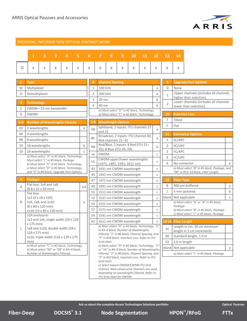
ORDERING INFORMATION OPTICAL DWDM/CWDM
1 2 3 4 5 6 7 8 9 10 11 12 13 14
O x x x x x x x x x x x x x x
1 Type
M Multiplexer
D Demultiplexer
2 Technology
C CWDM—15 nm bandwidth
D DWDM
3‐4 Number of Wavelengths Filtered
02 2 wavelengths a
04 4 wavelengths
08 8 wavelengths
10 10 wavelengths b
16 16 wavelengths c
a) Must select "D" in #2 block, Technology. Must select "L" in #5 block, Package.b) Must select "C" in #2 block, Technology.c) Must select "D" in #2 block, Technology, and "0" in #9 block, Upgrade Port Options.
5 Package
AFlat box: 1x4 and 1x8 (8.8 x 31 x 50 mm)
a,b
B
Flat box:1x2 (9 x 18 x 120)1x4, 1x8, and 1x10 (8 x 80 x 120 mm)1x16 (15 x 80 x 120 mm)
a
L
LGX enclosure:1x2 and 1x4, single width (29 x 129 x 175 mm)1x8 and 1x10, double width (58 x 129 x 175 mm)1x16, triple width (116 x 129 x 175 mm)a) Must select "C" in #2 block, Technology.b) Must select "04" or "08" in #3–4 block, Number of Wavelengths Filtered.
6 Channel Spacing
1 100 GHz a
2 200 GHz a
3 20 nm b
4 40 nm b
a) Must select "D" in #2 block, Technology.b) Must select "C" in #2 block, Technology.
7‐8 Wavelength Options
SBSplitband, 2 inputs: ITU channels 27 and 31
a
BCBroadcast, 2 inputs: ITU channel 40; Red channels 21–35
a
RBRed/Blue, 2 inputs: 8 Red (ITU 21–35); 8 Blue (ITU 45–59)
b
xx DWDM c
ULCWDM upper/lower wavelengths (1471, 1491, 1591, 1611 nm)
c
43 1431 nm CWDM wavelength c
45 1451 nm CWDM wavelength c
47 1471 nm CWDM wavelength c
49 1491 nm CWDM wavelength c
51 1511 nm CWDM wavelength c
53 1531 nm CWDM wavelength c
55 1551 nm CWDM wavelength c
57 1571 nm CWDM wavelength c
59 1591 nm CWDM wavelength c
61 1611 nm CWDM wavelength c
a) Must select "D" in #2 block, Technology, "2" in #3–4 block, Number of Wavelengths Filtered, "2" in #6 block, Channel Spacing, and "F" in #10 block, Insertion Loss. Refer to ITU Grid chart.b) Must select "D" in #2 block, Technology, "2" or "16" in #3–4 block, Number of Wavelengths Filtered, "2" in #6 block, Channel Spacing, and "F" in #10 block, Insertion Loss. Refer to ITU Grid chart.c) Select lowest DWDM/CWDM ITU Grid channel. Next consecutive channels are used, depending on wavelengths filtered. Refer to ITU Grid chart for DWDM.
9 Upgrade Port Options
0 None
1Upper channels (includes all channels higher than selection)
2Lower channels (includes all channels lower than selection)
10 Insertion Loss
T Tilted
F Flat
11 Connector Options
1 SC/APC
2 SC/UPC
3 FC/APC
4 FC/UPC
6 No connector a
a) Must select "B" in #5 block, Package, and "00" in #13–14 block, Fiber Length.
12 Fiber Type
B 900 µm buffered a
J 3 mm jacketed b
blank Not applicable c
a) Must select "A" or "B" in #5 block, Package.b) Must select "B" in #5 block, Package.c) Must select "L" in #5 block, Package.
13‐14 Fiber Length
xxLength in cm, 30 cm minimum length in 5 cm increments
00 Standard length, 1.0 m
02 2.0 m length
blank Not applicable a
a) Must select "L" in #5 block, Package
Node SegmentationDOCSIS® 3.1Fiber‐Deep HPON™/RFoG FTTx
Ask us about the complete Access Technologies Solutions portfolio: Optical Passives
ARRIS Optical Passives and Accessories
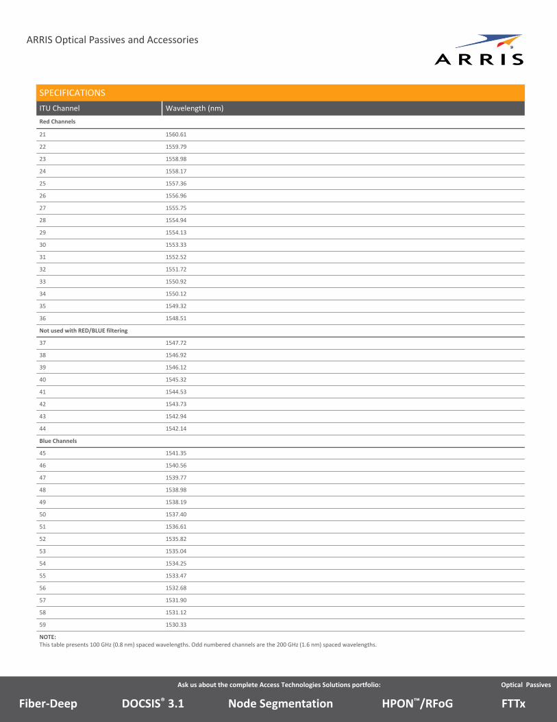
SPECIFICATIONS
ITU Channel Wavelength (nm)
Red Channels
21 1560.61
22 1559.79
23 1558.98
24 1558.17
25 1557.36
26 1556.96
27 1555.75
28 1554.94
29 1554.13
30 1553.33
31 1552.52
32 1551.72
33 1550.92
34 1550.12
35 1549.32
36 1548.51
Not used with RED/BLUE filtering
37 1547.72
38 1546.92
39 1546.12
40 1545.32
41 1544.53
42 1543.73
43 1542.94
44 1542.14
Blue Channels
45 1541.35
46 1540.56
47 1539.77
48 1538.98
49 1538.19
50 1537.40
51 1536.61
52 1535.82
53 1535.04
54 1534.25
55 1533.47
56 1532.68
57 1531.90
58 1531.12
59 1530.33
NOTE:This table presents 100 GHz (0.8 nm) spaced wavelengths. Odd numbered channels are the 200 GHz (1.6 nm) spaced wavelengths.
Node SegmentationDOCSIS® 3.1Fiber‐Deep HPON™/RFoG FTTx
ARRIS Optical Passives and Accessories
Single Channel 3‐Port Optical Add‐Drop Multiplexers
ARRIS OADM series optical add‐drop multiplexers are 3‐port, single channel multiplexers that add or drop a preselected
wavelength from an optical fiber containing a number of wavelengths, which are located in either the CWDM wavelength region
(1430 to 1610 nm) or the DWDM wavelength region (1530 to 1560 nm). For most inside plant applications, the OADM’s single‐
width protective enclosure allows it to be used either independently or mounted with other optical cards in an LGX‐style optical
shelf, such as the ARRIS OS1000. For most outside plant applications, OADMs are packaged in either a splice‐tube or a flat‐box
type package, which is suitable for mounting inside a splice enclosure or a fiber management tray. In addition, standard or user‐
specified fiber pigtail lengths are provided, as well as various connector options and fiber types.
Features
• User‐selectable add‐drop wavelengths in the CWDM and DWDM wavelength regions
• Low insertion loss and high isolation
• Available with standard connector options
• LGX‐style, splice‐tube, or flat‐box enclosure types
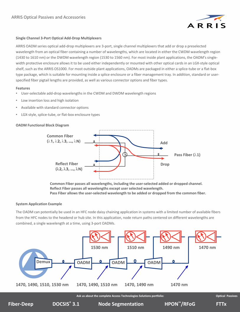
OADM Functional Block Diagram
Ask us about the complete Access Technologies Solutions portfolio: Optical Passives
Common Fiber(1, 2, 3, ..., N)
Reflect Fiber(2, 3, ..., N)
Pass Fiber (1)
Drop
Add
Common Fiber passes all wavelengths, including the user‐selected added or dropped channel.Reflect Fiber passes all wavelengths except user selected wavelength.Pass Fiber allows the user‐selected wavelength to be added or dropped from the common fiber.
System Application Example
The OADM can potentially be used in an HFC node daisy chaining application in systems with a limited number of available fibers
from the HFC nodes to the headend or hub site. In this application, node return paths centered on different wavelengths are
combined, a single wavelength at a time, using 3‐port OADMs.
Demux
1470, 1490, 1510, 1530 nm
1530 nm 1510 nm 1490 nm 1470 nm
OADM OADM OADM
1470, 1490, 1510 nm 1470, 1490 nm 1470 nm
Node SegmentationDOCSIS® 3.1Fiber‐Deep HPON™/RFoG FTTx
Ask us about the complete Access Technologies Solutions portfolio: Optical Passives
ARRIS Optical Passives and Accessories
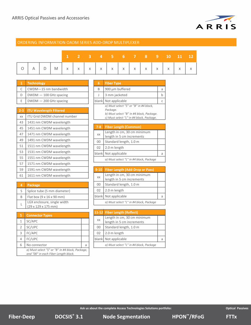
ORDERING INFORMATION OADM SERIES ADD‐DROP MULTIPLEXER
1 2 3 4 5 6 7 8 9 10 11 12
O A D M x x x x x x x x x x x x
1 Technology
C CWDM—15 nm bandwidth
D DWDM — 100 GHz spacing
E DWDM — 200 GHz spacing
2‐3 ITU Wavelength Filtered
xx ITU Grid DWDM channel number
43 1431 nm CWDM wavelength
45 1451 nm CWDM wavelength
47 1471 nm CWDM wavelength
49 1491 nm CWDM wavelength
51 1511 nm CWDM wavelength
53 1531 nm CWDM wavelength
55 1551 nm CWDM wavelength
57 1571 nm CWDM wavelength
59 1591 nm CWDM wavelength
61 1611 nm CWDM wavelength
4 Package
S Splice tube (5 mm diameter)
B Flat box (9 x 16 x 90 mm)
LLGX enclosure, single width (29 x 129 x 175 mm)
5 Connector Types
1 SC/APC
2 SC/UPC
3 FC/APC
4 FC/UPC
6 No connector a
a) Must select "S" or "B" in #4 block, Package, and "00" in each Fiber Length block.
6 Fiber Type
B 900 µm buffered a
J 3 mm jacketed b
blank Not applicable c
a) Must select "S" or "B" in #4 block, Package.b) Must select "B" in #4 block, Package.c) Must select "L" in #4 block, Package.
7‐8 Fiber Length (Common)
xxLength in cm, 30 cm minimum length in 5 cm increments
00 Standard length, 1.0 m
02 2.0 m length
blank Not applicable a
a) Must select "L" in #4 block, Package
9‐10 Fiber Length (Add‐Drop or Pass)
xxLength in cm, 30 cm minimum length in 5 cm increments
00 Standard length, 1.0 m
02 2.0 m length
blank Not applicable a
a) Must select "L" in #4 block, Package
11‐12 Fiber Length (Reflect)
xxLength in cm, 30 cm minimum length in 5 cm increments
00 Standard length, 1.0 m
02 2.0 m length
blank Not applicable a
a) Must select "L" in #4 block, Package
Node SegmentationDOCSIS® 3.1Fiber‐Deep HPON™/RFoG FTTx
Wavelength Division Multiplexers
WDMs are passive optical products that enable simultaneous transmission of two wavelengths in the 1310 nm region, the 1550
nm region, and the CWDM region (1460 to 1620 nm), with options available for 20 dB or 40 dB of optical isolation between the
two wavelength ports.
For most inside plant applications, each WDM is packaged in a small, single‐width sheet metal enclosure, which mounts into an
industry standard LGX‐style shelf, such as the ARRIS OS1000 optical shelf. For LGX enclosures, each WDM can be used individually
or it can be mounted into another enclosure suitable for mounting multiple passive optical products in a headend equipment
rack.
For most outside plant applications, each WDM is packaged in a splice‐tube or flat‐box package, which is suitable for mounting in
a splice enclosure or fiber management tray. For outside plant applications, standard or user specified fiber pigtail lengths are
provided, as well as various connector options and fiber types (900 µm loose tube or buffered and 3 mm jacketed).
Features
• Allows simultaneous transmission of optical signals in the 1310 nm, 1550 nm, and CWDM regions over one optical fiber
• Low insertion loss with two available performance grades, standard and high isolation
• Available with standard connector options
• LGX‐style, splice‐tube, or flat‐box enclosure types
Applications
In most system applications, the WDM will be used to combine signals in the 1310 nm region, the 1550 nm region, or the CWDM
region (1460 to 1620 nm) onto a single optical fiber. WDMs are typically used to conserve fiber usage in system applications in
which fibers are limited. WDMs can be used for unidirectional and bidirectional transport applications. Unidirectional transport
applications typically consist of two transmitters (1310 and 1550 nm region), which are combined using the WDM onto a single
fiber and sent to a receiving node where the signals are demultiplexed, using another WDM, and sent to separate receivers.
Bidirectional transport applications typically consist of end to end applications where a transmitter and a receiver (1310 and 1550
nm region) reside at each end of the network and are combined using WDMs for single fiber transport.
For inside plant applications, the WDM will typically be installed in a temperature controlled, inside plant application, such as a
headend or hub site. For outside plant applications, the WDM will typically be installed in a non‐temperature controlled
environment, such as a splice enclosure or node fiber management tray.
Ask us about the complete Access Technologies Solutions portfolio: Optical Passives
ARRIS Optical Passives and Accessories
Node SegmentationDOCSIS® 3.1Fiber‐Deep HPON™/RFoG FTTx
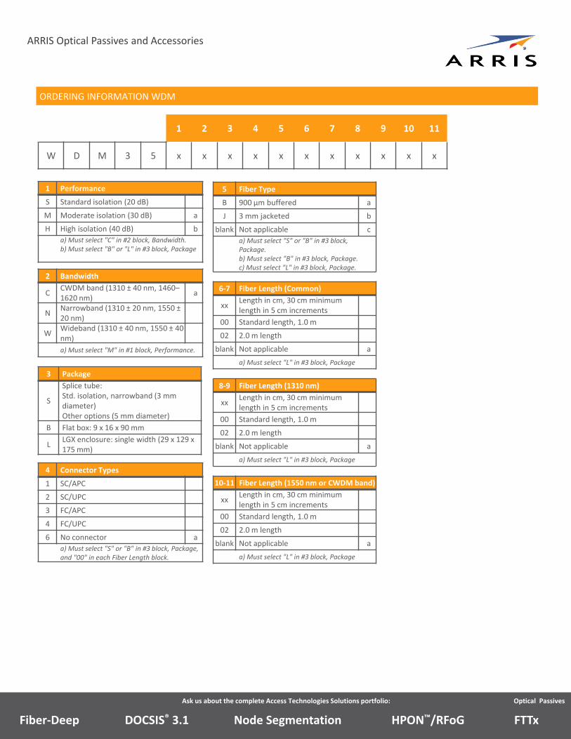
1 Performance
S Standard isolation (20 dB)
M Moderate isolation (30 dB) a
H High isolation (40 dB) b
a) Must select "C" in #2 block, Bandwidth.b) Must select "B" or "L" in #3 block, Package
ORDERING INFORMATION WDM
1 2 3 4 5 6 7 8 9 10 11
W D M 3 5 x x x x x x x x x x x
3 Package
S
Splice tube:Std. isolation, narrowband (3 mm diameter)Other options (5 mm diameter)
B Flat box: 9 x 16 x 90 mm
LLGX enclosure: single width (29 x 129 x 175 mm)
4 Connector Types
1 SC/APC
2 SC/UPC
3 FC/APC
4 FC/UPC
6 No connector a
a) Must select "S" or "B" in #3 block, Package, and "00" in each Fiber Length block.
5 Fiber Type
B 900 µm buffered a
J 3 mm jacketed b
blank Not applicable c
a) Must select "S" or "B" in #3 block, Package.b) Must select "B" in #3 block, Package.c) Must select "L" in #3 block, Package.
6‐7 Fiber Length (Common)
xxLength in cm, 30 cm minimum length in 5 cm increments
00 Standard length, 1.0 m
02 2.0 m length
blank Not applicable a
a) Must select "L" in #3 block, Package
8‐9 Fiber Length (1310 nm)
xxLength in cm, 30 cm minimum length in 5 cm increments
00 Standard length, 1.0 m
02 2.0 m length
blank Not applicable a
a) Must select "L" in #3 block, Package
10‐11 Fiber Length (1550 nm or CWDM band)
xxLength in cm, 30 cm minimum length in 5 cm increments
00 Standard length, 1.0 m
02 2.0 m length
blank Not applicable a
a) Must select "L" in #3 block, Package
2 Bandwidth
CCWDM band (1310 ± 40 nm, 1460–1620 nm)
a
NNarrowband (1310 ± 20 nm, 1550 ±20 nm)
WWideband (1310 ± 40 nm, 1550 ± 40 nm)
a) Must select "M" in #1 block, Performance.
Ask us about the complete Access Technologies Solutions portfolio: Optical Passives
ARRIS Optical Passives and Accessories
Node SegmentationDOCSIS® 3.1Fiber‐Deep HPON™/RFoG FTTx
OC Series Optical Couplers
ARRIS OC series dual window optical couplers are based on an array of up to seven optical 1x2 coupler/splitters packaged in a
protective enclosure. Each card has 1 or 2 inputs and 2 to 32 outputs, depending on the model, and can pass wavelengths in the
1310 nm and 1550 nm regions. Cards can be added in series to accommodate more than eight outputs. The optical loss from the
input to each output can be varied to maximize the efficiency of the optical links.
For most inside plant applications, each coupler’s protective enclosure allows it to be used either independently or mounted with
other optical cards in an LGX‐style optical shelf, such as the ARRIS OS1000 optical shelf. Couplers with up to five outputs are
single‐width cards, using one slot in an optical shelf. Cards with six to eight outputs are double‐width cards, using two slots in an
optical shelf.
For most outside plant applications, the couplers are packaged in either a splice‐tube or a flat‐box type package, which is suitable
for mounting inside a splice enclosure or a fiber management tray. In addition, standard or user‐specified fiber pigtail lengths are
provided, as well as various connector options and fiber types.
The OC series couplers allow one transmitter to serve multiple receivers. In certain applications, the couplers may be used instead
to combine optical signals.
Features
• Allow one transmitter to serve multiple receivers
• Available with standard connector options
• LGX‐style, splice‐tube, or flat‐box enclosure types
• A 2x2 coupler card is available for easy optical combining/splitting
Ask us about the complete Access Technologies Solutions portfolio: Optical Passives
ARRIS Optical Passives and Accessories
Node SegmentationDOCSIS® 3.1Fiber‐Deep HPON™/RFoG FTTx
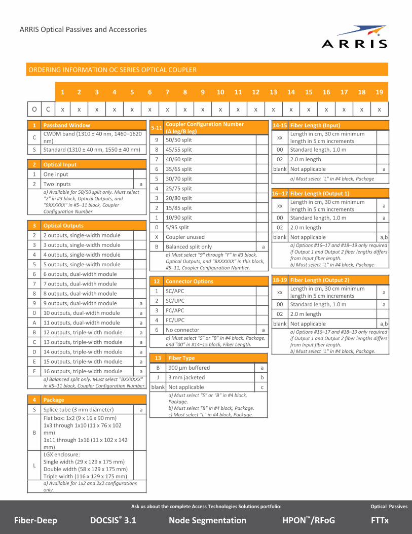
5‐11Coupler Configuration Number (A leg/B leg)
9 50/50 split
8 45/55 split
7 40/60 split
6 35/65 split
5 30/70 split
4 25/75 split
3 20/80 split
2 15/85 split
1 10/90 split
0 5/95 split
X Coupler unused
B Balanced split only a
a) Must select "9" through "F" in #3 block, Optical Outputs, and "BXXXXXX" in this block, #5–11, Coupler Configuration Number.
3 Optical Outputs
2 2 outputs, single‐width module
3 3 outputs, single‐width module
4 4 outputs, single‐width module
5 5 outputs, single‐width module
6 6 outputs, dual‐width module
7 7 outputs, dual‐width module
8 8 outputs, dual‐width module
9 9 outputs, dual‐width module a
0 10 outputs, dual‐width module a
A 11 outputs, dual‐width module a
B 12 outputs, triple‐width module a
C 13 outputs, triple‐width module a
D 14 outputs, triple‐width module a
E 15 outputs, triple‐width module a
F 16 outputs, triple‐width module a
a) Balanced split only. Must select "BXXXXXX" in #5–11 block, Coupler Configuration Number.
1 Passband Window
CCWDM band (1310 ± 40 nm, 1460–1620 nm)
S Standard (1310 ± 40 nm, 1550 ± 40 nm)
ORDERING INFORMATION OC SERIES OPTICAL COUPLER
1 2 3 4 5 6 7 8 9 10 11 12 13 14 15 16 17 18 19
O C x x x x x x x x x x x x x x x x x x x
12 Connector Options
1 SC/APC
2 SC/UPC
3 FC/APC
4 FC/UPC
6 No connector a
a) Must select "S" or "B" in #4 block, Package, and "00" in #14–15 block, Fiber Length.
13 Fiber Type
B 900 µm buffered a
J 3 mm jacketed b
blank Not applicable c
a) Must select "S" or "B" in #4 block, Package.b) Must select "B" in #4 block, Package.c) Must select "L" in #4 block, Package.
14‐15 Fiber Length (Input)
xxLength in cm, 30 cm minimum length in 5 cm increments
00 Standard length, 1.0 m
02 2.0 m length
blank Not applicable a
a) Must select "L" in #4 block, Package
16‐‐17 Fiber Length (Output 1)
xxLength in cm, 30 cm minimum length in 5 cm increments
a
00 Standard length, 1.0 m a
02 2.0 m length
blank Not applicable a,b
a) Options #16–17 and #18–19 only required if Output 1 and Output 2 fiber lengths differs from Input fiber length.b) Must select "L" in #4 block, Package
18‐19 Fiber Length (Output 2)
xxLength in cm, 30 cm minimum length in 5 cm increments
a
00 Standard length, 1.0 m a
02 2.0 m length
blank Not applicable a,b
a) Options #16–17 and #18–19 only required if Output 1 and Output 2 fiber lengths differs from Input fiber length.b) Must select "L" in #4 block, Package.
2 Optical Input
1 One input
2 Two inputs a
a) Available for 50/50 split only. Must select "2" in #3 block, Optical Outputs, and "9XXXXXX" in #5–11 block, Coupler Configuration Number.
4 Package
S Splice tube (3 mm diameter) a
B
Flat box: 1x2 (9 x 16 x 90 mm)1x3 through 1x10 (11 x 76 x 102 mm)1x11 through 1x16 (11 x 102 x 142 mm)
L
LGX enclosure:Single width (29 x 129 x 175 mm)Double width (58 x 129 x 175 mm)Triple width (116 x 129 x 175 mm)a) Available for 1x2 and 2x2 configurations only.
Ask us about the complete Access Technologies Solutions portfolio: Optical Passives
ARRIS Optical Passives and Accessories
Node SegmentationDOCSIS® 3.1Fiber‐Deep HPON™/RFoG FTTx
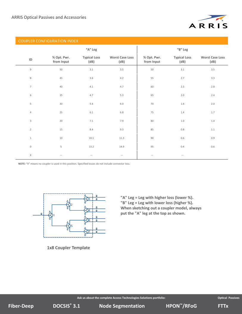
COUPLER CONFIGURATION INDEX
“A” Leg “B” Leg
ID% Opt. Pwr. from Input
Typical Loss (dB)
Worst Case Loss (dB)
% Opt. Pwr. from Input
Typical Loss (dB)
Worst Case Loss (dB)
9 50 3.1 3.5 50 3.1 3.5
8 45 3.6 4.2 55 2.7 3.3
7 40 4.1 4.7 60 2.3 2.8
6 35 4.7 5.3 65 2.0 2.4
5 30 5.4 6.0 70 1.6 2.0
4 25 6.1 6.8 75 1.4 1.7
3 20 7.1 7.9 80 1.0 1.4
2 15 8.4 9.3 85 0.8 1.1
1 10 10.1 11.3 90 0.6 0.9
0 5 13.2 14.9 95 0.4 0.6
X — — — — —
NOTE: “X” means no coupler is used in this position. Specified losses do not include connector loss.
1x8 Coupler Template
"A" Leg = Leg with higher loss (lower %)."B" Leg = Leg with lower loss (higher %).When sketching out a coupler model, always put the "A" leg at the top as shown.
Ask us about the complete Access Technologies Solutions portfolio: Optical Passives
ARRIS Optical Passives and Accessories
Node SegmentationDOCSIS® 3.1Fiber‐Deep HPON™/RFoG FTTx
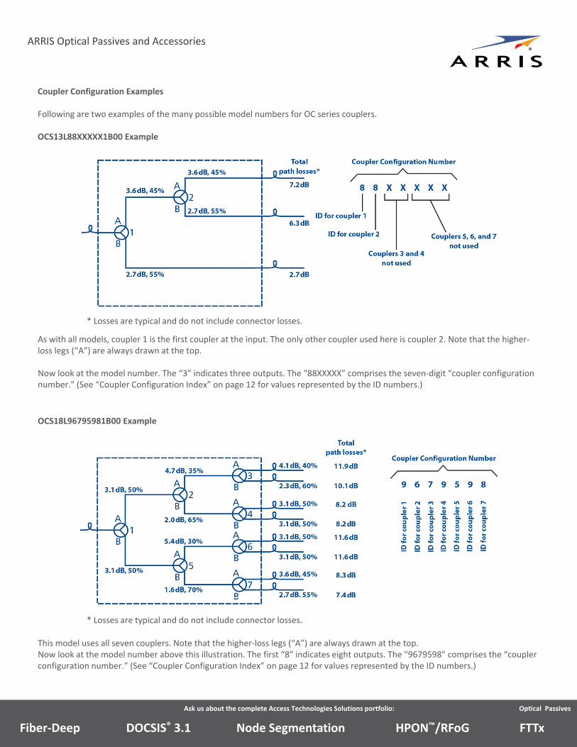
Coupler Configuration Examples
Following are two examples of the many possible model numbers for OC series couplers.
OCS13L88XXXXX1B00 Example
* Losses are typical and do not include connector losses.
As with all models, coupler 1 is the first coupler at the input. The only other coupler used here is coupler 2. Note that the higher‐loss legs (“A”) are always drawn at the top.
Now look at the model number. The “3” indicates three outputs. The "88XXXXX" comprises the seven‐digit “coupler configuration number.” (See “Coupler Configuration Index” on page 12 for values represented by the ID numbers.)
OCS18L96795981B00 Example
* Losses are typical and do not include connector losses.
This model uses all seven couplers. Note that the higher‐loss legs (“A”) are always drawn at the top.Now look at the model number above this illustration. The first “8” indicates eight outputs. The "9679598" comprises the “coupler configuration number.” (See “Coupler Configuration Index” on page 12 for values represented by the ID numbers.)
Ask us about the complete Access Technologies Solutions portfolio: Optical Passives
ARRIS Optical Passives and Accessories
Node SegmentationDOCSIS® 3.1Fiber‐Deep HPON™/RFoG FTTx
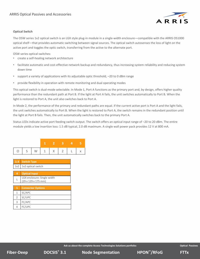
Optical Switch
The OSW series 1x2 optical switch is an LGX style plug‐in module in a single‐width enclosure—compatible with the ARRIS OS1000
optical shelf—that provides automatic switching between signal sources. The optical switch autosenses the loss of light on the
active port and toggles the optic switch, transferring from the active to the alternate port.
OSW series optical switches:
• create a self‐healing network architecture
• facilitate automatic and cost‐effective network backup and redundancy, thus increasing system reliability and reducing system
down time
• support a variety of applications with its adjustable optic threshold, –20 to 0 dBm range
• provide flexibility in operation with remote monitoring and dual operating modes
This optical switch is dual‐mode selectable. In Mode 1, Port A functions as the primary port and, by design, offers higher quality
performance than the redundant path at Port B. If the light at Port A fails, the unit switches automatically to Port B. When the
light is restored to Port A, the unit also switches back to Port A.
In Mode 2, the performance of the primary and redundant paths are equal. If the current active port is Port A and the light fails,
the unit switches automatically to Port B. When the light is restored to Port A, the switch remains in the redundant position until
the light at Port B fails. Then, the unit automatically switches back to the primary Port A.
Status LEDs indicate active port feeding switch output. The switch offers an optical input range of –20 to 20 dBm. The entire
module yields a low insertion loss: 1.5 dB typical, 2.0 dB maximum. A single wall power pack provides 12 V at 800 mA.
1 2 3 4 5
O S W 1 X 2 L x
1‐3 Switch Type
1x2 1x2 optical switch
4 Optical Input
LLGX enclosure: Single width (29 x 129 x 175 mm)
5 Connector Options
1 SC/APC
2 SC/UPC
3 FC/APC
4 FC/UPC
Ask us about the complete Access Technologies Solutions portfolio: Optical Passives
ARRIS Optical Passives and Accessories
Node SegmentationDOCSIS® 3.1Fiber‐Deep HPON™/RFoG FTTx
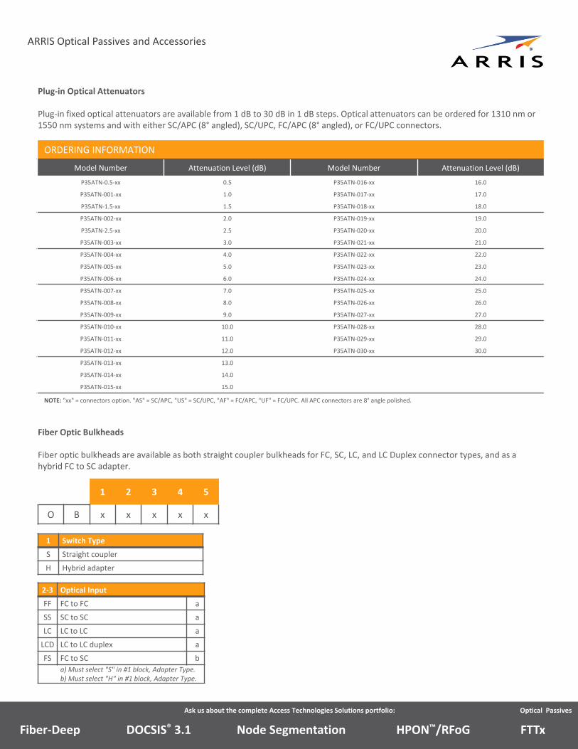
Plug‐in Optical Attenuators
Plug‐in fixed optical attenuators are available from 1 dB to 30 dB in 1 dB steps. Optical attenuators can be ordered for 1310 nm or 1550 nm systems and with either SC/APC (8° angled), SC/UPC, FC/APC (8° angled), or FC/UPC connectors.
ORDERING INFORMATION
Model Number Attenuation Level (dB) Model Number Attenuation Level (dB)
P35ATN‐0.5‐xx 0.5 P35ATN‐016‐xx 16.0
P35ATN‐001‐xx 1.0 P35ATN‐017‐xx 17.0
P35ATN‐1.5‐xx 1.5 P35ATN‐018‐xx 18.0
P35ATN‐002‐xx 2.0 P35ATN‐019‐xx 19.0
P35ATN‐2.5‐xx 2.5 P35ATN‐020‐xx 20.0
P35ATN‐003‐xx 3.0 P35ATN‐021‐xx 21.0
P35ATN‐004‐xx 4.0 P35ATN‐022‐xx 22.0
P35ATN‐005‐xx 5.0 P35ATN‐023‐xx 23.0
P35ATN‐006‐xx 6.0 P35ATN‐024‐xx 24.0
P35ATN‐007‐xx 7.0 P35ATN‐025‐xx 25.0
P35ATN‐008‐xx 8.0 P35ATN‐026‐xx 26.0
P35ATN‐009‐xx 9.0 P35ATN‐027‐xx 27.0
P35ATN‐010‐xx 10.0 P35ATN‐028‐xx 28.0
P35ATN‐011‐xx 11.0 P35ATN‐029‐xx 29.0
P35ATN‐012‐xx 12.0 P35ATN‐030‐xx 30.0
P35ATN‐013‐xx 13.0
P35ATN‐014‐xx 14.0
P35ATN‐015‐xx 15.0
NOTE: "xx" = connectors option. "AS" = SC/APC, "US" = SC/UPC, "AF" = FC/APC, "UF" = FC/UPC. All APC connectors are 8° angle polished.
Fiber Optic Bulkheads
Fiber optic bulkheads are available as both straight coupler bulkheads for FC, SC, LC, and LC Duplex connector types, and as a hybrid FC to SC adapter.
1 2 3 4 5
O B x x x x x
1 Switch Type
S Straight coupler
H Hybrid adapter
2‐3 Optical Input
FF FC to FC a
SS SC to SC a
LC LC to LC a
LCD LC to LC duplex a
FS FC to SC b
a) Must select "S" in #1 block, Adapter Type.b) Must select "H" in #1 block, Adapter Type.
Ask us about the complete Access Technologies Solutions portfolio: Optical Passives
ARRIS Optical Passives and Accessories
Node SegmentationDOCSIS® 3.1Fiber‐Deep HPON™/RFoG FTTx
Note: Specifications are subject to change without notice.
Copyright Statement: ©ARRIS Enterprises, LLC, 2018. All rights reserved. No part of this publication may be
reproduced in any form or by any means or used to make any derivative work (such as translation,
transformation, or adaptation) without written permission from ARRIS Enterprises, LLC (“ARRIS”). ARRIS
reserves the right to revise this publication and to make changes in content from time to time without
obligation on the part of ARRIS to provide notification of such revision or change. ARRIS and the ARRIS logo
are registered trademarks of ARRIS Enterprises, LLC. Other trademarks and trade names may be used in this
document to refer to either the entities claiming the marks or the names of their products. ARRIS disclaims
proprietary interest in the marks and names of others. The capabilities, system requirements and/or
compatibility with third‐party products described herein are subject to change without notice.
Optical Passives_DS_24JAN18
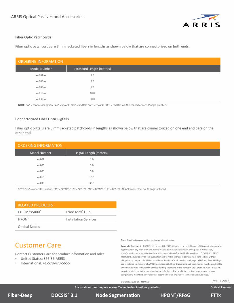
Fiber Optic Patchcords
Fiber optic patchcords are 3 mm jacketed fibers in lengths as shown below that are connectorized on both ends.
ORDERING INFORMATION
Model Number Patchcord Length (meters)
xx‐001‐xx 1.0
xx‐003‐xx 3.0
xx‐005‐xx 5.0
xx‐010‐xx 10.0
xx‐030‐xx 30.0
NOTE: "xx" = connectors option. "AS" = SC/APC, "US" = SC/UPC, "AF" = FC/APC, "UF" = FC/UPC. All APC connectors are 8° angle polished.
Connectorized Fiber Optic Pigtails
Fiber optic pigtails are 3 mm jacketed patchcords in lengths as shown below that are connectorized on one end and bare on the other end.
ORDERING INFORMATION
Model Number Pigtail Length (meters)
xx‐001 1.0
xx‐003 3.0
xx‐005 5.0
xx‐010 10.0
xx‐030 30.0
NOTE: "xx" = connectors option. "AS" = SC/APC, "US" = SC/UPC, "AF" = FC/APC, "UF" = FC/UPC. All APC connectors are 8° angle polished.
Ask us about the complete Access Technologies Solutions portfolio: Optical Passives
ARRIS Optical Passives and Accessories
Customer CareContact Customer Care for product information and sales:• United States: 866‐36‐ARRIS• International: +1‐678‐473‐5656
Node SegmentationDOCSIS® 3.1Fiber‐Deep HPON™/RFoG FTTx
RELATED PRODUCTS
CHP Max5000® Trans Max® Hub
HPON™ Installation Services
Optical Nodes
(rev 01-2018)