Array Imaging System Software - Mailing & Bindery Systems Inc
100
Array Imaging System Software Version 3 8101 Cessna Avenue Gaithersburg, MD 20879-4164 800.728.0154 tel 301.990.3155 fax www.mcspro.com USA
Transcript of Array Imaging System Software - Mailing & Bindery Systems Inc

Array Imaging System SoftwareVersion 3
8101 Cessna AvenueGaithersburg, MD 20879-4164
800.728.0154 tel301.990.3155 fax
www.mcspro.com
USA


MCSArray Imaging System Software
Release 3.0
MCSArrayUM607 • Revision 0

© 2007 MCS Incorporated All rights reserved.
MCS retains all ownership rights to all computer programs offered by MCS, their products, and the contents of this manual. The source code for software is a confidential trade secret of MCS. You may not attempt to decipher, decompile, develop or otherwise reverse engineer MCS software, firmware, or products. Information necessary to achieve interoperability is furnished upon request.
This manual is furnished under license and may be used or copied only in accordance with the terms of such license. The information in the manual is furnished for informational use only, is subject to change without notice, and should not be construed as commitment by MCS. MCS assumes no responsibility or liability for any errors or inaccuracies that may appear in this manual. No part of this manual may be reproduced, stored in a retrieval system, or transmitted, in any form or by any means, electronic, mechanical, recording, or otherwise, without the express written permission of MCS.
Existing artwork or images that you may desire to scan may be protected by copyright law. Be sure to obtain permission for use of existing artwork.
Trademarks
This product carries the trademark of MCS. All the trademarks of component parts used by MCS in the manufacture of this product are the property of their respective owners. The MCS logo is a registered trademark of MCS.
Microsoft and Windows are registered trademarks of Microsoft Corporation. All other brand or product names are trademarks or registered trademarks of their respective companies or organizations.
Manufacturer's StatementLimited Warranty, Disclaimer, Limitation of Liability
MCS warrants this product for a limited period of time from initial purchase against defects in materials and workmanship. This warranty does not cover damage caused by misuse or abuse of this product or by acts of God or accidents or other causes beyond the control of MCS. Also not covered by this warranty are claims other than by the original purchaser. Your sole remedy and our sole liability to you shall be to repair or replace this product at our discretion if it does not meet the requirements of this warranty.
MCS and its distributors shall under no circumstances be liable for any damages arising from the use of or the inability to use this product or from any loss of revenue or profit, business interruption, or other loss which may arise from the use of this product.
THE WARRANTIES ABOVE ARE EXCLUSIVE AND IN LIEU OF ALL OTHER WARRANTIES, WHETHER EXPRESS OR IMPLIED, INCLUDING THE IMPLIED WARRANTIES OF MERCHANTABILITY AND FITNESS FOR A PARTICULAR PURPOSE.

Contents
About this Guide.................................................................................1-1Intended Audience............................................................................................. 1-1Conventions....................................................................................................... 1-1Getting Help ....................................................................................................... 1-1
Getting Started....................................................................................2-1Software Installation........................................................................................... 2-1Dongle Installation ............................................................................................. 2-3First-time Installation of Device Driver .............................................................. 2-3
Wizard aborted ............................................................................................. 2-4
Understanding the Interface..............................................................3-1Opening the Application..................................................................................... 3-1The Main Window .............................................................................................. 3-2Title Bar.............................................................................................................. 3-2Menu Bar ........................................................................................................... 3-3Toolbar............................................................................................................... 3-3
Job and Data Tab......................................................................................... 3-3Template Tab ............................................................................................... 3-3
Display Area....................................................................................................... 3-3Tab Selection Area ............................................................................................ 3-4Status Bar .......................................................................................................... 3-4View Menu ......................................................................................................... 3-5
Data Entry Font ............................................................................................ 3-5Customize..................................................................................................... 3-5Options ......................................................................................................... 3-6
Importing Data ....................................................................................4-1Data File Options ............................................................................................... 4-1
Custom Data Files ........................................................................................ 4-2Opening Data Files ............................................................................................ 4-4Viewing Records ................................................................................................ 4-5Finding Records................................................................................................. 4-5Validating Postal Barcodes................................................................................ 4-6Setting Start and Stop Records ......................................................................... 4-6Changing the Data Font..................................................................................... 4-7Field Header ...................................................................................................... 4-7
TOC-1
Using Templates .................................................................................5-1Creating and Saving Templates......................................................................... 5-1
Opening Existing Templates......................................................................... 5-1Creating New Templates .............................................................................. 5-2Saving templates .......................................................................................... 5-2
Template Setup.................................................................................................. 5-2Understanding the Template Display Area ........................................................ 5-3Placing New Items ............................................................................................. 5-3
Record Blocks .............................................................................................. 5-4Message Lines ............................................................................................. 5-8Indicia ......................................................................................................... 5-10Bitmaps....................................................................................................... 5-11Barcodes .................................................................................................... 5-14Counter....................................................................................................... 5-18Time Stamp ................................................................................................ 5-18Shift Code................................................................................................... 5-20User Insert .................................................................................................. 5-20
Editing Options................................................................................................. 5-21Selecting Objects........................................................................................ 5-21Moving and Rotating................................................................................... 5-22Object Properties........................................................................................ 5-22Duplicating and Deleting............................................................................. 5-22Aligning Objects.......................................................................................... 5-22Avoiding Pen Boundaries ........................................................................... 5-22Move to Print Area...................................................................................... 5-23Docking and Attaching................................................................................ 5-23Layering Objects......................................................................................... 5-25Set Background.......................................................................................... 5-25Scanning Data............................................................................................ 5-26
Viewing Options............................................................................................... 5-26Print Proof ........................................................................................................ 5-26
Creating Jobs......................................................................................6-1Creating and Saving Jobs.................................................................................. 6-1
Opening Existing Jobs.................................................................................. 6-1Creating New Jobs ....................................................................................... 6-2Saving Jobs.................................................................................................. 6-2
System Setup..................................................................................................... 6-2Board Settings.............................................................................................. 6-3Pen Settings ................................................................................................. 6-4
TOC-2
User’s Manual
Printing Jobs.......................................................................................7-1Print Setup ......................................................................................................... 7-1
Print Setup Tab............................................................................................. 7-1Error Tab ...................................................................................................... 7-2Sort Tab........................................................................................................ 7-3Counters Tab................................................................................................ 7-4Time Stamps Tab ......................................................................................... 7-6Shift Definitions Tab ..................................................................................... 7-7Clocks Tab.................................................................................................... 7-9User Inserts Tab......................................................................................... 7-10Other........................................................................................................... 7-11
Checking Ink Levels......................................................................................... 7-12Printing From the Job Tab ............................................................................... 7-13Checking Print Status ...................................................................................... 7-14
Changing Print Status Display.................................................................... 7-15Viewing the Job Log ................................................................................... 7-18
Reprints............................................................................................................ 7-18
Troubleshooting .................................................................................8-1Reprogramming Boards..................................................................................... 8-1Calibrating Encoder Ticks per Inch, Pen Spacing, Head Distances .................. 8-2Pulse-Spitting Implementation ........................................................................... 8-5
Theory of Operation...................................................................................... 8-5Smart-Spitting Implementation........................................................................... 8-6
Theory of Operation:..................................................................................... 8-6Pulse-Warming Implementation......................................................................... 8-7
Pulse-Warming Addendum........................................................................... 8-7Printing Blank Pages.......................................................................................... 8-8Unrecognized Fonts........................................................................................... 8-9File Control Settings........................................................................................... 8-9Ink Bleeding on Barcodes................................................................................ 8-10Error Codes...................................................................................................... 8-11Warnings.......................................................................................................... 8-12
Hardware Installation .........................................................................9-1Firewire Hookup................................................................................................. 9-1Rack Firewire Hook-up ...................................................................................... 9-1
Small Enclosure Firewire Hook-up ............................................................... 9-2New Head-hookup Procedure............................................................................ 9-2Daisy-chaining Controllers ................................................................................. 9-2........................................................................................................................... 9-3
TOC-3User’s Manual

TOC-4
User’s Manual

Chapter 1: About this Guide
In This Chapter
• Intended Audience
• Conventions
• Getting Help
The Array Imaging System Software is a Windows-based software application that provides the ability to lay out and print direct mail.
Note: The Array Imaging System Software v3.0 may be installed on any Array Imaging System; however, only systems that have been upgraded with the 3.0 dongle (hardware key) can print OneCodes and at 200 dpi, although these two features may be created in the software.
Intended Audience
This guide is intended for use by MCS equipment operators.
Basic knowledge of the Microsoft Windows® operating system and some experience with printing equipment is assumed.
Conventions
The following conventions are used in this guide.
Getting Help
A complete on-line help system is available in the Array Imaging System Software interface by selecting the Help item in the Menu bar or the Help icon on the toolbar.
If you need further assistance, please contact MCS via e-mail at [email protected] or call 800.728.0154. Telephone support for MCS Inc. sold equipment is available 8:30am to 6:30pm EST Monday through Friday and is free of charge.
Note: To locate your program location and version you can look in your Help>About window or select Ctrl-Alt-1 and Ctrl-Alt-2 while in the Job Log window.
Convention Description
Bold Actions you should take such as text or data to be typed exactly or items to click.
Italics Items to type in which you must supply a value.
1-1

Getting Help
About this Guide
1-2User’s Manual

Chapter 2: Getting Started
In This Chapter
• Software Installation
• Dongle Installation
• First-time Installation of Device Driver
The Array Imaging System Software is a software application that allows you to lay out direct mail pieces and print them. Although most of the work you do to create and print direct mail pieces is performed through the application interface, you may also have to make some physical adjustments to the printing equipment in order for your run to print correctly.
Array Imaging System Software has three main sections: the job, the template, and data. You create the job and the template, but you have the ability to only manipulate data. Data is supplied to you.
The general steps to producing direct mail through Array Imaging System Software are:
1. Import Data. See “Importing Data” on page 4-1.
You must obtain data files.2. Perform Print Setup.
See “Print Setup” on page 7-1.
3. Create a Template. See “Using Templates” on page 5-1.
A template is the actual layout of the material you wish to print.
4. Create a Job. See “Creating Jobs” on page 6-1.
The job consists of data, a template, and system settings. See “System Setup” on page 6-2 to create and enter System Settings.
5. Print the Job. See “Printing Jobs” on page 7-1.
Print test runs and make physical adjustments as necessary to ensure print quality.
Software Installation
The first installation of Array Imaging System Software is done by an MCS technician at your facility. After that, you are responsible for system upgrades.
Minimum system requirements to perform upgrades are:
• Pentium processor• Windows 2000 or greater• 128 MB RAM• CD ROM drive
2-1

Software Installation
Getting Started
The system should be turned off when installing or uninstalling software.
If an upgrade/downgrade is being performed, the system must be powered-down then up again after the new version is installed. This is because the Operating System will not know to reload the new device-driver into RAM until the device goes away and comes back again. The “Blue-Screen-of-Death” may result upon plug-in if this has not been performed.
There is no way to manually install or uninstall the software on a PC by deleting or copying files. You must run Setup.exe to install the software.
To install/upgrade the software:
1. Backup existing Array Imaging System Software files.
Array Imaging System Software job have files have a PJB extension and the templates have a PTL extension. Data file extensions depend upon the originating application or file type.
2. Uninstall any currently installed version using the Windows Remove Programs mechanism for doing so.
Access this window by selecting Start>Control Panel>Add or Remove Programs and then select the Array Software. Then click Remove.
The following files will remain in the installation folder after the Uninstall completes:PenInfo.ini
Pen ink-level and warming information.Setup.cfg
User-specific setup options.System.dat
User interface defaults information.
Any or all of these files can be manually deleted or left as is so the new installation will use them. All of them will be automatically recreated by the application (with default values) if they are not present.
Note: Later versions may have added settings to Setup.cfg. The only way to see those new settings after the new install is by deleting the current setup.cfg, which will force the application to create a new “default” setup.cfg the next time it runs.
The uninstall script also removes our device driver from the system:C:\WINNT\System32\drivers\AT1394.sys
Note that you can right-click on AT1394.sys in “My Computer” or “Windows Explorer” to see its version.
3. Disable any anti-virus applications.
You can usually do this by right-clicking the application’s icon in your system tray. After Array Imaging System Software installation is complete, be sure to enable your virus protection.
4. Run Setup.exe for the version you would like to install.
If you are starting with a zip file, unzip it first to the local hard drive and make sure you specify that folders in the zip file be honored when unzipping. Locate the setup.exe file and double-click it.
2-2User’s Manual

Dongle InstallationGetting Started
The installation puts the device-driver for that version inC:\WINNT\System32\drivers\AT1394.sys
and will overwrite any existing one. This is desired because if you are going back one or more versions the “old” device driver is required.
5. Follow the setup wizard.
6. Verify firmware.
Make sure the controller’s formatter boards have the appropriate firmware to accept new software. Look at the board numbers in the log are of the Job window when the controller is first turned on. The next to the last two-digit number should read "07", indicating the updated firmware exists. For example, Board Version: 09020300-07-02.
Dongle Installation
Version 3.0 and higher requires a hardware dongle to use the software. A dongle is a hardware device that communicates with the MCS software to allow its use. If you attempt to use the software without the dongle installed, it will not function properly. You will receive an error stating “Printer Setup Error.”
To install the dongle:
1. From the installing CD, double-click the file DongleInstallation/Hdd32.exe.
This executable installs the drivers to operate the dongle.2. Follow the instructions.
3. Double-click the file DongleInstallation/DongleReader.exe.
This program verifies driver installation and proper operation.4. Insert the Dongle into a USB port.
The dongle operates in any USB port; however, an internal port is recommended for added security.
First-time Installation of Device Driver
Although the device driver is installed to the Drivers folder by the Installation script, the operating system does not yet know that the driver should be loaded when the controller is plugged in for the first time. Plug-N-Play is used to associate that driver with our device. The first time the unit is connected to the PC via firewire and powered-on, a New Hardware Found window is displayed by the Operating System. The following instructions show how to associate our driver with our device (they depend slightly on the Operating System and/or Service Pack):
1. At the Welcome to the Found New Hardware Wizard window select Install from a list or specific location (Advanced) and click Next.
You will need to specify where the driver install file is rather than have the Operating System try to locate an existing driver. The system needs to access our AT1394.inf file to determine how to associate the driver. That file is installed to the application’s folder.
2. Click the Browse button and navigate to select the following folder:C:\Program Files\PrintMail WideArray\PrintMail WideArray
2-3User’s Manual
First-time Installation of Device Driver
Getting Started
orC:\Program Files\MCS\Array_Software_name
And click OK.3. Click Finish.
The wizard installs the driver and indicates it completed successfully.
You may verify the driver is installed by locating the “IEEE 1394 Printer” “Array Technologies AT-2500 Printer” in the Device Manager (see “Wizard aborted” on page 2-4 for instructions on getting to the Device Manager).
Note: The unit must be powered-on and connected.
If the “New Hardware Found” wizard is aborted before it completes, it will not appear again on further add/removals of the device! Note that someone else may have already aborted the wizard without your knowledge before you did. The wizard is the only way the driver can be installed. If the system is in the state where the wizard was aborted then nothing appears in the application's log when the system is connected to the PC.
Therefore, the unit should not be connected to the PC before the software is installed or before an operator is ready to complete the wizard.
Wizard aborted
If the wizard was aborted you can cause it to reappear the next time the system is connected by following these steps:
1. Leave the system on and plugged into the PC.
2. Go to the Device Manager.
Start>Control Panel>System3. Click the Hardware tab.
4. Click on the Device Manager button to open the Device Manager.
5. Locate Array Technologies Inc. AT-2500 Printer in the list of devices.
It should be under the Other devices node and have a question mark icon with an exclamation point beside it.
6. Delete the entry from the list by highlighting it and pressing the Delete key.
7. Select Yes or OK from the Confirm Device Removal dialog prompt.
8. Turn the system off.
9. Turn the system on.
10. The New Hardware Found dialog wizard should appear and you can follow the directions in “First-time Installation of Device Driver ” on page 2-3 above to associate our driver with the device.
2-4User’s Manual

Chapter 3: Understanding the Interface
In This Chapter
• Opening the Application
• The Main Window
• Title Bar
• Menu Bar
• Toolbar
• Display Area
• Tab Selection Area
• Status Bar
• View Menu
Array Imaging System Software is a Microsoft Windows-style application. It is important to understand how the interface works so that you may use the interface most effectively.
Opening the Application
Array Imaging System Software is a standard Windows application and can be opened in many ways, one of which is described here.
To open the application:
1. Double click the Array Software icon on your desktop.
The application opens and a splash screen appears.
After a few seconds the splash screen disappears and the Main window remains open.
Note: You may open the application using other Windows standard techniques.
3-1

The Main Window
Understanding the Interface
The Main Window
The Main Window is the primary point of entry for all tasks. This window is broken down into many areas as annotated below. Each area is described in the sections that follow.
Title Bar
The Title bar displays the name of the program, a minimize button, a maximize/restore button, and a close button.
Title BarMenu Bar
Tab Selection AreaStatus Bar
Display Area
Toolbars
3-2User’s Manual

Menu BarUnderstanding the Interface
Menu Bar
This standard Windows feature contains pulldown menus to select functions. Functions which cannot be used appear dimmed (gray). Items in the Menu Bar are interactive. They change as tabs are selected in the tab selection area.
Toolbar
The Toolbar contains rows of iconic buttons that provide additional functions applicable to the displayed window. Icons in the toolbar are interactive. They change as tabs are selected in the tab selection area. You can customize the icons displayed in the toolbar as described in “Customize” on page 3-5. Default values are shown here for commonly used toolbars.
Job and Data Tab
Template Tab
Display Area
The display area is the area in which functions appear. When you select a tab in the tab selection area, the display area is repopulated with that information. You then work within the display area to execute your tasks.
New Job
Open Job
Save Job
Help
Find
Record NavigationGo to Record Number
Help
Select Mode
New Record
New Message
Indicia
Bitmap
Conditional BitmapShow Data
Postal BarcodeBarcode
Zoom
3-3User’s Manual

Tab Selection Area
Understanding the Interface
Tab Selection Area
The tab selection area contains two tabs. The Job and Template tabs provide the major functionality for Array Imaging System Software. Selecting a tab changes the display area and changes the options available via the menu bar and toolbar. In addition, the Job tab has two sub-tabs, Log and Data, which change the display area within the Job window.
Status Bar
Located at the bottom of the application window, the Status Bar shows a variety of status information.
3-4User’s Manual

View MenuUnderstanding the Interface
View Menu
The View menu contains items that change the way items are displayed on screen. These changes apply to all windows in the application.
Data Entry Font
The data entry font selection allows you change the font in which data is displayed on screen in application windows. This has no effect on how data is printed.
Note: Only Open Type fonts with True Type outlines may be used in Array Imaging System Software. See “Unrecognized Fonts” on page 8-9 for details.
To change the data entry font:
1. Select Data Entry Font from the View menu.
The Font menu appears.
2. Change the font criteria as desired.
3. Click OK.
Customize
The customize option allows you select which icons are shown in the toolbars.
3-5User’s Manual

View Menu
Understanding the Interface
To change icons displayed in toolbars:
1. Select Customize from the View menu and select the desired toolbar to change.
The toolbar window appears.
2. Use the Add and Remove arrow buttons to change the icons displayed.
3. Click OK.
Options
The options item allows you specify some general preferences.
To specify preferences:
1. Select Options from the View menu.
The Options window appears.
2. Check the box if you wish to save the template with the job and select the number of names to show in the recent files list.
3. Click OK.
3-6User’s Manual

Chapter 4: Importing Data
In This Chapter
• Data File Options
• Opening Data Files
• Viewing Records
• Finding Records
• Validating Postal Barcodes
• Setting Start and Stop Records
• Changing the Data Font
• Field Header
Data files are supplied by customers. Operators cannot change data content but can peruse and select data as needed. It is important to set data file options so that data is accurately imported and printed.
Data File Options
Data file options allow you specify how you want imported data to be handled in the application.
Note: Data file options must be set prior to opening data files.
To enter data file options:
1. Select Data File Options from the File menu.
The File Format Detail window appears.
2. Select the desired file format from the Defined File Types pulldown.
4-1

Data File Options
Importing Data
You can provide detail for a variety of file formats including:
3. Enter the remaining parameters for each data file type as indicated above.
4. Click OK to save your settings.
Custom Data Files
Custom data files require the most configuration because ImagePro800 does not assume anything about the file type. Every available data file option is described in this section.
To enter custom data file options:
1. Select Data File Options from the File menu.
The File Format Detail window appears.2. Select Custom from the Defined File Types pulldown.
File Type Description
Custom Allows you specify custom file format details. All fields are available in this format as described in “Custom Data Files” on page 4-2 below.
1 Up format Postal barcode, Sort Description and Code Page fields are available as described in steps 6, 7, and 8 below.
Text I Postal barcode, Sort Description and Code Page fields are available as described in steps 6, 7, and 8 below. You can also enter a fixed number of fields in the Record description.
Text II Postal barcode, Sort Description and Code Page fields are available as described in steps 6, 7, and 8 below.
CSV Comma Separated Value formats. These files are typically exported from
spreadsheet programs like Microsoft Excel®. Postal barcode, Sort Description and Code Page fields are available as described in steps 6, 7, and 8 below.
SCITEX The SCITEX proprietary file format. Postal barcode, Sort Description and Code Page fields are available as described in steps 6, 7, and 8 below. You can also enter a fixed number of fields in the Record Description and enter the field description as described in step 5 below.
Database Files exported from database programs such as Microsoft Access®. Postal barcode and Sort Description fields are available as described in steps 6, 7, and 8 below. You can also enter Database Parameters as described in step 3.
Variable Enter variable record and field descriptions as shown in steps 4 and 5 below. Postal barcode, Sort Description and Code Page fields are available as described in steps 6, 7, and 8 below.
4-2User’s Manual

Data File OptionsImporting Data
The window is repopulated with available fields.
3. Click the radio button for the data source type.
You can choose either file/text, variable, or database. Select variable or database only if you know this file is of that type.
For database file types, enter the Database Parameters Selection Statement only if your database has multiple tables and go to step 6. For file/text and variable go to step 4.
Note: The Database Selection Statement is rarely used and you must have knowledge of SQL to use it. It requires the SQL statement select * from name.
4. Enter the Record Description.
For File/text select the end-of-record marker or fixed number of fields.
If you select end-of-record marker, select the end-of-line marker or enter the end-of-record delimiter. An end-of-line marker will be a carriage return (CR) or line feed (LF). A record delimiter is the hexadecimal value for a specific character such as a comma. The value for comma (,) is U002C. A pipe (|) is U007C. If you do not know the hexidecimal value for your character, see a data processing professional or the internet for assistance.
For Variable select the end-of-record marker or fixed length characters and enter the Number Of Starting Records to skip.
5. Enter the Field Description
For File/text select the end-of-record marker or fixed number of fields.
If you select end-of-record marker, select the end-of-line marker or enter the end-of-record delimiter. An end-of-line marker will be a carriage return (CR) or line feed (LF). A record delimiter is the hexadecimal value for a specific character such as a comma.
4-3User’s Manual

Opening Data Files
Importing Data
The value for comma (,) is U002C. A pipe (|) is U007C. If you do not know the hexidecimal value for your character see a data processing professional or the internet for assistance.
For Variable, use the Add/Modify field definition button to add field level definitions. Enter the Field number, starting and ending positions, and field length for each field and click OK. The data populates the field description table.
6. Enter the Postal Barcode Description.
Postal bar codes are 12 digits long. They include the zip code plus four, delivery point, and a check digit. This area tells the application where to look for this value and to verify if it is correct. If you select None, the software will not look for this value. If you choose Select From Data, the software looks at all fields for this data. You may also specify a field number or the field number along with a specific amount of characters to look at. You may also enter postal barcode information as described in “Postal Barcode” on page 5-16.
Note: If you specify fields to search and there are no postal barcodes in those fields, the application will delete data in that field. Specify fields only when you are sure they contain postal barcodes.
7. Enter the Sort description.
If you wish printing to pause for sorting purposes, enter the field at which you wish the pause to occur. This can be used to create a visual queue for operators. Sort settings are also required. See “Sort Tab” on page 7-3 for sort settings. An example sort setting is illustrated in the diagram below.
8. Select the Code Page from the pulldown.
These options select the standard used to display text. ANSI-Latin is most often used for the american alphabet, but you may need to change this setting.
Note: This field is not applicable to database file types.
9. Click OK to save your settings.
Opening Data Files
Data files must be opened and reviewed as well as attached to jobs. Data files are not created in Array Imaging System Software. They are supplied by the printing client and can be of a variety of formats. See “Data File Options” on page 4-1 for data file format information.
Sort at field X causes a pause in printing
4-4User’s Manual

Viewing RecordsImporting Data
Note: Path information is saved in jobs. When opening jobs with data files that have previously been attached, you may receive error messages if the file no longer resides at the same path. If this happens, accept the error messages and open the file from its new location.
To open the data files:
1. Click the Data tab.
You can open Data files with or without the Data tab selected, but you must click the Data tab to view the data.
Note: Make sure you have selected the desired Data File Type in the Data File Options window prior to attempting to open a data file. See “Data File Options” on page 4-1.
2. Select Open Data Files from the File menu.
The Open Data File window appears.
3. Navigate to the file’s location and click Open.
The file is opened and now populates the display area of the Data tab.
Viewing Records
You can use the Data menu options First Record, Previous Record, Next Record, Last Record, and Go To Record to navigate throughout the data file. You may also use the record navigation icons on the Toolbar.
Finding Records
You can find specific records using the Find function.
To find records:
1. Select the Job tab and then the Data tab.
2. Select Find from the Data menu.
4-5User’s Manual

Validating Postal Barcodes
Importing Data
The Find window appears.
3. Enter the desired criteria.
Enter a value to find such as a number or name. Select to search from the current cursor location or the whole file and indicate whether to search up or down. If desired, check the box to match the case (upper, lower, or mixed) as you typed it.
4. Click Find.
The row is highlighted. You can use the Find Next option in the data menu to find the next occurrence of this search criteria.
If you are printing and searched for this item to add to reprints list, click the Add To Reprints button. See “Reprints” on page 7-18 for more information on reprints.
Validating Postal Barcodes
If the data file contains postal barcodes and you have placed postal barcodes in the template, you can check that the codes are valid in the imported file. The system reviews the field specified in the database options window. If the data does not validate, errors are listed in the job window.
To validate postal barcodes:
1. Make sure the data file contains postal barcodes.
2. Specify the field in the field containing the barcode in the Data file options window.
You can also highlight the column containing the field.3. Select the Job tab and then the Data tab.
4. Select Validate from the Edit menu.
Success or failure messages will display in the error log area of the Job window.
Setting Start and Stop Records
You can specify the start and stop records for printing a job.
To set start or stop records:
1. Select the Data tab.
2. Highlight the desired row for the stop or start record.
4-6User’s Manual

Changing the Data FontImporting Data
3. Right-click the desired row and select Start Record or Stop Record.
The row number is displayed in the Job window.
Changing the Data Font
You can change the font used to print data. The font change is reflected on screen in the data table as well as in print.
Note: Only Open Type fonts with True Type outlines may be used in Array Imaging System Software. See “Unrecognized Fonts” on page 8-9 for details.
To change the data font:
1. Select Data Font from the View menu.
The Font window appears. This same window is used for Data Entry font as well.2. Select the desired criteria.
You can select the font, font size, and weight from the scrolling lists. You can also choose a strikeout and underline effect. Leave the script as Western unless you know specifically that you need one of the other languages listed. If so, you can click the Advanced button for other language options. A sample of the font is displayed in the sample box and you can enter specific text in the text box to see how it looks in the font. The full character set is displayed in the code page table.
3. Click OK.
Field Header
For data file types with field headers, you can specify what actions to take on field headers.
4-7User’s Manual

Field Header
Importing Data
4-8User’s Manual

Chapter 5: Using Templates
In This Chapter
• Creating and Saving Templates
• Template Setup
• Understanding the Template Display Area
• Placing New Items
• Editing Options
• Viewing Options
• Print Proof
Array Imaging System Software allows you to create templates which are the basic design of your print piece. The template contains all of the layout information for your piece.
Note: Print Setup as described in “Print Setup” on page 7-1 should be performed prior to laying out your template.
Creating and Saving Templates
You can create a new template from scratch, open an existing template, and save a template. Template file names are displayed in the job window, but are not editable there. Template file names appear in red if they have changes that have not been saved. An asterick (*) also appears in the title bar if you have unsaved changes.
Opening Existing Templates
If you wish to print a template that has already been created or make modifications to a template, you must open that template.
To open an existing saved template:
1. Click the Template tab.
2. Select Open template from the File menu.
When you save a template its path information is saved; therefore, when you try to open a template and its path information cannot be found, you will see a series of error messages. You can accept these messages and navigate to the location where the template file is now stored. This happens when you share template files on different computers. Click Yes on error dialogs and indicate the new file path.
The template contains system settings. If you load the Data file and Template separately, you may not get all settings associated with the template, such as print settings.
Templates have the .ptl extension.
3. Locate the desired file using Windows navigation methods.
4. Click Open.
5-1

Template Setup
Using Templates
The template is opened in the display area. The template name, data file, and template file are listed. There is a print button and a variety of status and log information.
Note: You can use the Save As feature to save this template under a new name. All of its characteristics are saved and you can use this as a basis for a new template.
Creating New Templates
A new template provides a blank sheet for you to layout direct mail items.
To open a new template:
1. Click the Template tab.
2. Select New template from the File menu.
If an existing template is open, you may receive a message to save that template. The template tab’s display area is repopulated and the new template’s title is Untitled.
3. Import Data as described in “Importing Data” on page 4-1, create a template as described in “Creating and Saving Templates” on page 5-1, and specify system and print settings as specified in “System Setup” on page 6-2 and “Print Setup” on page 7-1, respectively.
4. Save the template by selecting Save template from the File menu.
5. Provide a new template name and click Save.
Saving templates
You can save a template that has been opened and modified or that is new.
To save a new template:
1. Click the Template tab.
2. Open an existing template or create a new template.
3. Make any changes.
4. Save the template by selecting Save template from the File menu.
5. Click Save.
Note: You can use the Save As feature to save this template under a new name. All of its characteristics are saved and you can use this as a basis for a new template.
Template Setup
Make sure you have set clocks, time stamps, shift definitions, and user inserts before you enter items in templates. See “Print Setup” on page 7-1.
5-2User’s Manual

Understanding the Template Display AreaUsing Templates
Understanding the Template Display Area
The template display area shows each head board, pen board, and distance between head boards. It is important to understand the template so that you can appropriately place text and objects.
Head boards are 2 inches and pen boards are 1/2 inch. There are four pen boards to each 2 inch head board. Each pen board contains a single color ink. Depending on how you configure your system, the template layout may differ. For instance if your system is set to print two heads together, then four heads together, then two and then six. Your template would show white space with 6 blue pen lines (8 half-inch sections for eight heads), a grey divider which represents distance from top of piece (as specified in “System Setup” on page 6-2) and then the next section with for headboards and so on.
Note: If the items placed in the template do not print as expected, you may need to address calibration issues. See “Calibrating Encoder Ticks per Inch, Pen Spacing, Head Distances” on page 8-2.
Placing New Items
You can place a variety of items in your template. Once an item has been placed it can be edited as described in “Editing Options” on page 5-21. The following section describes how to place new items.
5-3User’s Manual

Placing New Items
Using Templates
Record Blocks
Record blocks are groups of text generated from your data. Data should be imported prior to placing record blocks. Each field of data is a separate line in the block. Field numbers are shown when the record block is placed.
If you wish to see the actual data, click the Show record data icon .
To place a record block:
1. Click the Template tab.
2. Select New Record Block from the New menu.
The text properties box appears with the text tab on top and the full record is placed in the template.
5-4User’s Manual

Placing New ItemsUsing Templates
3. Refine the data on the Text tab.
You can delete fields listed in the data display by clicking them.
You can add fields from the field list by clicking the field name. Fields are added where your cursor is placed in the data display. If the field names are not visible, click the Select the Fields button to show them. You can also add counters, time stamps, shifts, and user inserts by scrolling to the bottom of the field lists and clicking the desired item. Click the expansion symbol (+) to reveal the items under each category.
Note: Counters, time stamps, shifts, and user inserts must be created in Print Setup, as described in “Print Setup” on page 7-1, prior to invoking this window.
You can highlight fields in the data display and apply text effects such as bold, italic, strike through, size, and font.
You can word wrap, remove blank lines when printing, remove leading spaces from fields, add additional line spacing, or spread the spacing within the font (Font Width multiplier).
5-5User’s Manual

Placing New Items
Using Templates
4. Click the Text (more) tab and enter the desired criteria.
If word wrap was selected in the Text tab, you can select character-based word wrap.
Specify how to treat carriage returns and line feeds. Decide whether you want to make letters uppercase when printing and remove characters between fields if a field is blank.
5. Click the General tab and enter the desired criteria.
5-6User’s Manual

Placing New ItemsUsing Templates
Enter position and size values. Decide if you want to allow resizing, keep natural size, or force square. Most resizing keeps the image constrained to its original proportions. Forced square makes the image fit in a perfect square regardless of its original proportions. This can be useful if you wish the object to fit inside another square object.
6. Click the Advanced tab and enter the desired criteria.
Click Transparent to make the text transparent. This is selected by default and allows you to layer objects. Transparency allows you to see through to the objects below in the stack. Enter borders, margins, alignment, and anchor position for the record block.
7. Click OK.
8. Move the item to the desired location via editing techniques as described in “Editing Options” on page 5-21.
5-7User’s Manual

Placing New Items
Using Templates
If you choose to show data, the record block is populated with data from the data file.
Message Lines
Message lines use the same text entry techniques as record blocks. See “Record Blocks” on page 5-4. Instead of the record being displayed in the Data Display box, the words
5-8User’s Manual
Placing New ItemsUsing Templates
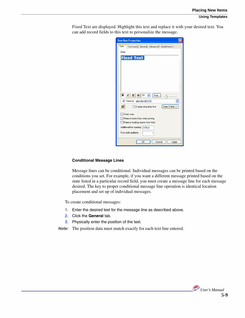
Fixed Text are displayed. Highlight this text and replace it with your desired text. You can add record fields to this text to personalize the message.
Conditional Message Lines
Message lines can be conditional. Individual messages can be printed based on the conditions you set. For example, if you want a different message printed based on the state listed in a particular record field, you must create a message line for each message desired. The key to proper conditional message line operation is identical location placement and set up of individual messages.
To create conditional messages:
1. Enter the desired text for the message line as described above.
2. Click the General tab.
3. Physically enter the position of the text.
Note: The position data must match exactly for each text line entered.
5-9User’s Manual

Placing New Items
Using Templates
4. Enter the conditional text settings.
You must enter the position. Click the Conditional check box and enter the source field and the specific condition for which you want this data displayed. If you select the Equal radio button, the specific condition will always be used if the value is found. If the value is not found, no text is displayed. If you select the Not Equal radio button, the text is displayed only if the source does not match the value displayed. For example, if you wish to send a general message such as “Friend,” unless you actually have a name value in the field, select the Not Equal function.
Indicia
Indicia uses the same text entry techniques as record blocks. See “Record Blocks” on page 5-4. Instead of the record being displayed in the Data Display box, the standard
5-10User’s Manual

Placing New ItemsUsing Templates
Indicia is displayed. You highlight this text and replace it with your desired text. You can add record fields to this text to personalize the message.
Bitmaps
Bitmaps are graphics files. The only type of graphics that can be imported into Array Imaging System Software are monochrome (one color) bitmaps (BMP). You must convert other graphic file formats to monochrome BMP prior to importing. You can import unconditional or conditional bitmaps.
Unconditional
Unconditional bitmaps are imported and may be resized using the editing tools as described in “Editing Options” on page 5-21.
To import an unconditional bitmap:
1. Click the Template tab.
2. Select Bitmap from the New menu.
The open dialog appears.
3. Locate and select the desired file by traditional Windows means.
4. Click Open.
The file is placed in the template and the Bitmap Properties window appears.
5. Make any changes to the bitmap properties by entering information in the tabs.
5-11User’s Manual

Placing New Items
Using Templates
The remaining tabs contain the same information described in “Record Blocks” on page 5-4.
6. Click the General tab.
7. Enter the desired criteria.
You can enter position and size information which dictates how the bitmap are placed.
8. Click the Advanced tab.
9. Enter the desired criteria.
You can enter information about borders and alignment and indicate whether the graphic is transparent.
10. Click the Attachments tab.
11. Enter the desired criteria.
If this item has been attached via the attachment options described in “Docking and Attaching” on page 5-23, you can modify attachment options. If the item is not attached, the items in this tab are not active.
12. Click OK.
Conditional
Conditional bitmaps are several bitmaps associated with a numeric field value in a data file. You specify the bitmap to be used, depending on the value in the data file. For example, the data file can have a field that indicates a different bitmap for each of 50 states, depending on where the resident lives. The field value would be 0 to 50. Map the the field values to the bitmap so that when the job is run, the correct bitmap is printed, based on the state.
Note: The data file must have a field containing conditional bitmap values to use this feature.
To import a conditional bitmap:
1. Click the Template tab.
2. Select Conditional Bitmap from the New menu.
5-12User’s Manual

Placing New ItemsUsing Templates
The Conditional Bitmap Properties dialog appears with the Conditional Bitmap tab on top.
3. Click Edit/Add or Quick Add/Update.
Edit/Add should be used when you have bitmaps with alphanumeric names or numeric names that are not in ascending numeric sequence. You must enter each bitmap individually. A new window appears.
Enter the Bitmap numeric value or browse to select the filename. Click OK. The files are added to the table. Click OK.
5-13User’s Manual

Placing New Items
Using Templates
Quick Add/Update is used when all bitmap files have a numeric value in ascending order, for example, if you have a number for each state. A new window appears.
Click Add/Update and navigate to select all the numbered files. Click Open. Values are shortcuts specified for the path to the files. Click Done. The files are added in the table. The system does the work to match the numbers to the conditions.
4. In both cases, on the Conditional Bitmap tab, check the box if values are numeric and select the field in the data file that contains the bitmap number.
The remaining tabs contain the same information described in “Record Blocks” on page 5-4.
5. Click the General tab.
6. Enter the desired criteria.
You can enter position and size information which dictates how the bitmap will be placed.
7. Click the Advanced tab.
8. Enter the desired criteria.
You can enter information about borders and alignment and indicate whether the graphic is transparent.
9. Click the Attachments tab.
10. Enter the desired criteria.
If this item has been attached via the attachment options described in “Docking and Attaching” on page 5-23, you can modify attachment options. If the item is not attached, the items in this tab are not active.
11. Click OK.
The file is placed in the template and can be edited as described in “Editing Options” on page 5-21.
Barcodes
Postal or standard barcodes may be placed in your template. All barcodes are limited to multiples of 90 degree rotation.
5-14User’s Manual

Placing New ItemsUsing Templates
Standard Barcode
You can choose from a variety of standard bar codes.
To insert standard barcodes:
1. Click the Template tab.
2. Select Barcode and then type of barcode you wish to insert from the New menu.
The Bar Code window appears with the Bar Code tab on top.
Note: The OneCode selection can be selected and configured for any Array Imaging System Software installation; however, it can be printed only if you have the 3.0 (or higher) dongle (hardware key). OneCode is the new USPS standard effective 2008.
3. Enter the desired properties for your bar code.
Click the ellipse button to select the text and field for the bar code. Click OK.
Enter sizing, check, and bar information. Check the show human characters box, if desired, and enter the desired properties.
5-15User’s Manual

Placing New Items
Using Templates
The OneCode window is unique.
The remaining tabs contain the same information described in “Record Blocks” on page 5-4.
4. Click the General tab.
5. Enter the desired criteria.
You can enter position and size information which dictates how the bitmap will be placed.
6. Click the Advanced tab.
7. Enter the desired criteria.
You can enter information about borders and alignment and indicate whether the graphic is transparent.
8. Click the Attachments tab.
9. Enter the desired criteria.
If this item has been attached via the attachment options described in “Docking and Attaching” on page 5-23, you can modify attachment options. If the item is not attached, the items in this tab are not active.
10. Click OK.
Postal Barcode
You can define the properties for Postal barcodes. Postal barcodes are graphical representations of a numeric zip code. You may want to keep barcodes within pen boundaries as shown in “Avoiding Pen Boundaries” on page 5-22.
5-16User’s Manual

Placing New ItemsUsing Templates
Note: If you rotate Postal barcodes, make sure the bars do not lay on pen boundaries. Use “Avoiding Pen Boundaries” on page 5-22.
To insert standard barcodes:
1. Click the Template tab.
2. Select Postal Barcode from the New menu.
The Postal BarCode window appears with the BarCode tab on top.
3. Enter the desired properties for your bar code.
Enter the desired dots per inch (dpi) to pitch properties. If you run a bar code’s bars over pen boundaries see “Avoiding Pen Boundaries” on page 5-22. You can also try to adjust the pitch to 20 bars per inch to avoid pen boundaries.
You can override standard postnet settings by clicking the ellipse button of the postnet override. Decide whether you want to allow 5/6 digit codes.
The remaining tabs contain the same information described in “Record Blocks” on page 5-4.
4. Click the General tab.
5. Enter the desired criteria.
You can enter position and size information which dictates how the bitmap will be placed.
6. Click the Advanced tab.
7. Enter the desired criteria.
You can enter information about borders and alignment and indicate whether the graphic is transparent.
8. Click the Attachments tab.
9. Enter the desired criteria.
5-17User’s Manual

Placing New Items
Using Templates
If this item has been attached via the attachment options described in “Docking and Attaching” on page 5-23, you can modify attachment options. If the item is not attached, the items in this tab are not active.
10. Click OK.
Counter
Counters use the same text entry techniques as record blocks. See “Record Blocks” on page 5-4. Instead of the record being displayed in the Data Display box the words Counter:Counter are displayed. Double-click the desired counter field in the field list to the left to select it.
Note: Counters, time stamps, shift codes, and user inserts must be created before invoking this item. See “Print Setup” on page 7-1 for details.
Time Stamp
Time Stamps use the same text entry techniques as record blocks. See “Record Blocks” on page 5-4. Instead of the record being displayed in the Data Display box the time
5-18User’s Manual
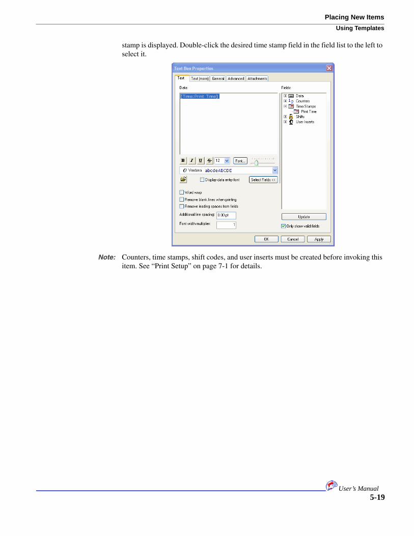
Placing New ItemsUsing Templates
stamp is displayed. Double-click the desired time stamp field in the field list to the left to select it.
Note: Counters, time stamps, shift codes, and user inserts must be created before invoking this item. See “Print Setup” on page 7-1 for details.
5-19User’s Manual

Placing New Items
Using Templates
Shift Code
Shift codes use the same text entry techniques as record blocks. See “Record Blocks” on page 5-4. Instead of the record being displayed in the Data Display box the shift code is displayed. Double-click the desired shift code field in the field list to the left to select it.
Note: Counters, time stamps, shift codes, and user inserts must be created before invoking this item. See “Print Setup” on page 7-1 for details.
User Insert
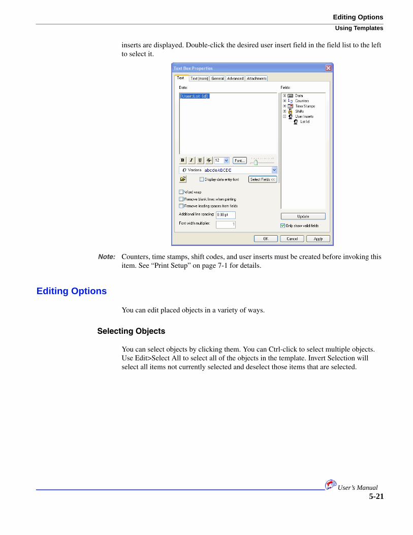
User Inserts use the same text entry techniques as record blocks. See “Record Blocks” on page 5-4. Instead of the record being displayed in the Data Display box the user
5-20User’s Manual
Editing OptionsUsing Templates
inserts are displayed. Double-click the desired user insert field in the field list to the left to select it.
Note: Counters, time stamps, shift codes, and user inserts must be created before invoking this item. See “Print Setup” on page 7-1 for details.
Editing Options
You can edit placed objects in a variety of ways.
Selecting Objects
You can select objects by clicking them. You can Ctrl-click to select multiple objects. Use Edit>Select All to select all of the objects in the template. Invert Selection will select all items not currently selected and deselect those items that are selected.
5-21User’s Manual

Editing Options
Using Templates
Moving and Rotating
You can select objects and then move and rotate them. You can move a selected object by holding down the left mouse button and moving the mouse. You rotate objects by placing the cursor over a corner handle of an object until the rotate symbol appears.
Once this symbol appears left-click and drag to the desired angle. You can also rotate and move objects based on setting in the object’s properties dialog as described in “Object Properties” on page 5-22.
Note: Some features no longer apply after rotation.
Object Properties
When a single object is selected, you can change a variety of properties for that object by selecting Edit>Properties. This is the same properties windows used to place the object. See the placement section for each object type for details on each tab on its properties window.
Duplicating and Deleting
You can select an object and make an exact copy of it using the Edit>Duplicate selection. Click an object and select Edit>Delete to delete the object.
Aligning Objects
You can align objects so that they line up perfectly with respect to each other.
To align objects:
1. Click the Template tab.
2. Ctrl-click to select the objects you wish to align.
3. Select Align and then the desired alignment type from the Edit menu.
Alignment types include top, bottom, left, right, abut top to bottom, and more. The objects are moved to the alignment specified.
Avoiding Pen Boundaries
In certain cases, it is not recommended to have objects lay on the blue line pen boundaries. This feature moves objects so that they avoid these lines. For example, a
5-22User’s Manual

Editing OptionsUsing Templates
barcode that lays on a pen boundary may not print the correct width of the bars that lay on the boundary. This could cause the code to scan incorrectly.
Note: You can also try adjusting the pitch of the barcode to 20 bars as described in “Postal Barcode” on page 5-16.
To avoid pen boundaries:
1. Click the Template tab.
2. Click the desired object(s).
3. Select Avoid Pen Boundaries from the Edit menu.
The object is moved to avoid pen boundaries.
Move to Print Area
You can select objects and have them moved to different print areas. Print areas are separated by the gray areas that are created by adding distance from top. Each print area represents a board or group of boards. The areas are numbered from the top of the template to the bottom.
To move objects to a different print area:
1. Click the Template tab.
2. Click the desired object(s).
3. Select Move to Print Area from the Edit menu.
A new window appears.
4. Select the desired print area from the pulldown.
5. Click OK.
The object is moved as specified.
Docking and Attaching
It is often easier to move objects around in the template when they are grouped together. Docking and attaching objects helps you move objects relationally.
Docking
Docking objects moves the objects together and groups them. They now act as one object and can not be moved independently.
5-23User’s Manual

Editing Options
Using Templates
To dock objects:
1. Click the Template tab.
2. Ctrl-click the desired objects.
3. Select Dock from the Edit menu.
The items are moved together and can now be moved around as one object.
Attaching
Attaching objects allows you move each object independently but with regard to the relationship specified. The objects are not moved together.
To attach objects:
1. Click the Template tab.
2. Ctrl-click the desired objects.
3. Select Attach (attachment type) from the Edit menu.
The object properties window appears for the first type of item you clicked. The attachment properties are recorded with the first object clicked. When objects are attached, their attachments tab becomes active in the object’s propertied window.
4. Select the desired type of attachment and specify an offset if desired.
5. Click OK.
The object is moved as specified.
5-24User’s Manual

Editing OptionsUsing Templates
Layering Objects
Objects may be laid on top of each other to achieve a desired look. The layering of objects results in their Z-order.
Note: When using these features, make sure the transparent box is checked in the object’s advanced tab properties.
Move to Front/Push to Back
You can move objects to the front and back of a stack as if objects were in a deck of cards.
To move objects front or back:
1. Click the Template tab.
2. Click the desired object(s).
3. Select the move option from the Edit menu.
The objects are moved.
Move Up/Down
Once objects are placed in a stack, you can move them up and down within the stack.
To move objects up or down:
1. Click the Template tab.
2. Click the desired object(s).
3. Select the move option from the Edit menu.
The objects are moved.
Set Background
It may be helpful to lay out your template with the actual printed piece as the background of your template. When you set a background, the original printed piece is placed at the back of the stack of objects but is not editable. It is unclickable. Background files can be bitmap (BMP), JPG, or GIF.
To set the background:
1. Click the Template tab.
2. Select Set Background from the Edit menu.
3. Navigate to and select the desired file by traditional Windows means.
4. Click Open.
The file is placed in the background.
5. Select Show Background Image from the View menu to see the image.
5-25User’s Manual

Viewing Options
Using Templates
Scanning Data
It is useful to scan data for the longest or largest field content. This will help you to provide adequate spacing for the largest content.
To scan for longest content:
1. Click the Template tab.
2. Click the desired record block.
Note: Make sure the show record data button is clicked on the toolbar.
3. Select Scan Data from the Edit menu.
The longest record is displayed in the record block.
Viewing Options
A variety of options under the View menu allows you to see gridlines and colors that can assist during layout. You can set the zoom level, show anchor points, show Z-order (layered order of objects), show attachments and dock markers, show pen colors (spot color editing), and set a grid. For a grid, you can specify whether objects snap to the grid and the distance between the vertical lines in the grid.
Print Proof
You can print to a regular office printer to review the template layout. This does not reflect any job settings, just the layout of the template.
To print a template proof:
1. Click the Template tab.
2. Select Print proof from the Edit menu.
3. Enter the desired printing characteristics.
4. Click Print.
5. Select the desired printer.
6. Click OK.
5-26User’s Manual

Chapter 6: Creating Jobs
In This Chapter
• Creating and Saving Jobs
• System Setup
Array Imaging System Software jobs are the control center for printing. The Job window shows a variety of status information and allows you to print the job. A job consists of data, a template, and all print and system settings. the creation of jobs and system settings is described in this chapter; however, job printing and print status are described in “Printing Jobs” on page 7-1.
Creating and Saving Jobs
You can create a new job from scratch, open an existing job, and save a job. Job file names are displayed in the job window, but are not editable there. Job file names appear in red if they have changes that have not been saved. Also, an asterick (*) appears in the title bar if you have unsaved changes.
Opening Existing Jobs
If you wish to print a job that has already been created or make modifications to a job, you must open that job.
To open an existing saved job:
1. Click the Job tab.
2. Select Open Job from the File menu.
When you save a job its path information is saved; therefore, when you try to open a job and its path information cannot be found, you will receive a series of error messages. You can accept these messages and navigate to the location where the job file is now stored. This happens when you share job files on different computers. Click Yes on error dialogs and indicate the new file path.
The Job contains system settings. If you load the Data file and Template separately, all settings associated with the job, such as print settings may not be included.
Note: You can adjust setting in the setup.cfg file to allow for portable job settings. See “File Control Settings” on page 8-9.
3. Locate the desired file using Windows navigation methods.
4. Click Open.
6-1

System Setup
Creating Jobs
The job is opened in the display area. The Job name, data file, and template file are listed. There is a print button and a variety of status and log information.
Note: You can use the Save As feature to save this job under a new name. All of its characteristics are saved and you can use this as a basis for a new job.
Creating New Jobs
You can create new jobs from scratch.
To open a new job:
1. Click the Job tab.
2. Select New Job from the File menu.
If an existing Job is open, you may receive a message to save that job. The Job tab’s display area is repopulated and the new Job’s title is Untitled.
3. Import Data as described in “Importing Data” on page 4-1, create a template as described in “Using Templates” on page 5-1, and specify system and print settings as specified in “System Setup” on page 6-2 and “Print Setup” on page 7-1, respectively.
4. Save the job by selecting Save Job from the File menu.
You may also click to save Jobs.
5. Provide a new job name and click Save.
6. You may now print the job as described in “Printing Jobs” on page 7-1.
Note: You can use the Save As feature to save this job under a new name. All of its characteristics are saved and you can use this as a basis for a new job.
Saving Jobs
You can save a job that has been opened and modified or that is new.
To save a new job:
1. Click the Job tab.
2. Open an existing job or create a new job.
3. Make any changes.
4. Save the job by selecting Save Job from the File menu.
5. Click Save.
Note: You can use the Save As feature to save this job under a new name. All of its characteristics are saved and you can use this as a basis for a new job.
System Setup
System setup is saved when the job is saved and specifies important information about how the template relates to the physical setup of the boards.
6-2User’s Manual

System SetupCreating Jobs
Note: Changing system setup after completion of a template may delete objects on the template.
You can view and change board and pen settings.
Board Settings
Board settings can be viewed or changed.
To perform system board setup:
1. Select System Setup from the File menu.
2. Click View Boards.
The window repopulates.
3. Indicate if the board is active or inactive by clicking the board’s Active/Inactive field.
4. If your job requires that you join boards, click the first joined board’s Join field. The second board’s configuration becomes gray and uneditable.
5. Enter the Distance From Top Of Piece for each board.
This value is calculated by adding the 2 inch value for each board plus half an inch between boards. The first board’s value is always 0 since it is at the top. If you have connected boards, the distance of both boards is added together and the complete distance is placed in the board after the connected board. The distances entered are reflected in the template layout. Grey spaces are placed between boards in the template.
6. Enter the Distance From Sensor for each board.
Note: The distance from sensor is an exact measurement of each board from the physical sensor on the table top. When the first piece hits the sensor, the system needs to know how far away from the sensor to print on each board. You use this distance plus the conveyer speed to print on the specified head. You should use alignment boxes as shown in “Calibrating Encoder Ticks per Inch, Pen Spacing, Head Distances” on page 8-2 to verify these calculations. These distances must be correct for the job to print without error.
6-3User’s Manual

System Setup
Creating Jobs
Note: Make sure your head boards are perfectly perpendicular to the paper before setting the distance from sensor. See “Calibrating Encoder Ticks per Inch, Pen Spacing, Head Distances” on page 8-2 for screw alignment.
7. Enter the Feed Direction.
This setting is rarely changed. It overrides the settings in Print Setup. One example of a reason to change this setting is printing on the sides of a box. Otherwise, leave the feed direction as set in Print Setup.
8. Click OK.
Pen Settings
By default the setup.cfg file controls pen settings and can be accessed manually in your installation folder. Initial changes are made via the setup.cfg file. Changes can be viewed via the application and future changes can be made via the application.
Initial Pen Setup
This setup is performed manually, without the application. By default no pens are created.
To perform initial system pen setup:
1. In your installation directory, open the file Setup.cfg.
This file can be opened in any text editor such as Notepad.
2. Save this file as a new name (such as Setup_old.cfg) using the Save As function in your text editor.
3. Open the Array Imaging System Software and notice that a new setup.cfg is created.
4. Close the application.
5. Open this new file in your text editor and make the desired changes.
At the bottom of the file, you see the settings below. There is a section for Boards 1 through 9. Change the 1 to a 0 in the lines that are bold to enable the board. You will need to change these to 0 only for the number of formatter boards that are in the system.
[Board1.Settings]SensorMargin.Source=0 (0-Job, 1-System)SensorMargin.System=0.000000FeedDirection.Source=0 (0-Job, 1-System)FeedDirection.System=LeftToRight (LeftToRight, RightToLeft)Pen1.SensorMarginMethod=1 (0-Job, 1-Board, 2-Pen)Pen1.SensorMargin=0.000000Pen1.SensorAdjustMethod=0 (0-Job, 1-System)Pen1.SensorMarginAdjust=0Pen1.PrintDirection=1 (0-Job, 1-Board, 2-LeftToRight, 3-RightToLeft)Pen2.SensorMarginMethod=1 (0-Job, 1-Board, 2-Pen)Pen2.SensorMargin=0.000000Pen2.SensorAdjustMethod=0 (0-Job, 1-System)Pen2.SensorMarginAdjust=0Pen2.PrintDirection=1 (0-Job, 1-Board, 2-LeftToRight, 3-RightToLeft)Pen3.SensorMarginMethod=1 (0-Job, 1-Board, 2-Pen)
6-4User’s Manual

System SetupCreating Jobs
Pen3.SensorMargin=0.000000Pen3.SensorAdjustMethod=0 (0-Job, 1-System)Pen3.SensorMarginAdjust=0Pen3.PrintDirection=1 (0-Job, 1-Board, 2-LeftToRight, 3-RightToLeft)Pen4.SensorMarginMethod=1 (0-Job, 1-Board, 2-Pen)Pen4.SensorMargin=0.000000Pen4.SensorAdjustMethod=0 (0-Job, 1-System)Pen4.SensorMarginAdjust=0Pen4.PrintDirection=1 (0-Job, 1-Board, 2-LeftToRight, 3-RightToLeft)
This example changes the setting for all four pens of Board 1. You need to repeat the change for Board 2, Board 3, etc., as needed.
6. Save these changes and close the file.
7. You may now make changes via the application GUI. See “Changing Pen Setup” on page 6-5 for information.
Changing Pen Setup
Once pens have been set up, you can make some adjustments via the application.
To view and change system pen setup:
1. Select System Setup from the File menu.
Note: You must have performed Initial Pen Setup for the pen settings to appear editable in this window. See “Initial Pen Setup” on page 6-4 for more information.
2. Click View Pens.
3. Adjust individual pen settings.
6-5User’s Manual

System Setup
Creating Jobs
6-6User’s Manual

Chapter 7: Printing Jobs
In This Chapter
• Print Setup
• Checking Ink Levels
• Printing From the Job Tab
• Checking Print Status
• Reprints
Once the Job is completely set up you can print it. It is recommended that you do some test printing before doing the complete run. It is especially important to check head alignment as described in “Calibrating Encoder Ticks per Inch, Pen Spacing, Head Distances” on page 8-2.
Print Setup
It is important that the job print setup be completed prior to printing. System setup should also be completed. See “System Setup” on page 6-2. Print setup should be done prior to template creation. There are settings in print setup that can be used in the template design.
Print Setup Tab
The print setup tab allows you to change the setup of the paper. These changes are reflected in the template tab.
To apply print settings:
1. Click the Template tab.
2. Select Print Setup from the File menu.
7-1

Print Setup
Printing Jobs
3. Click the Print Setup tab.
4. Select the Paper size and Paper orientation.
Height information is needed only if you use landscape orientation.
5. Select the Print Resolution.
Note: You may select any print resolution, but the 200 x 600 selection will print only if you have the 3.0 (or higher) dongle (hardware key).
6. Enter the Template Orientation.
The Template orientation should be the same as the Paper Orientation.7. Enter the Feed Direction and Print Orientation.
The Feed Direction determines which side feeds into the printer. If these settings are manually changed in System Setup, this pane turns red. You should verify these settings if a color change occurs. Feed Direction rarely changes. One reason to change this setting is when printing on the sides of a box. Different feed directions would be needed.
The Print Orientation is which way matter is printed on the paper.
8. Verify your changes in the Template and Printed Piece Preview boxes.
9. Click OK.
Error Tab
The Errors tab allows you to define how errors are reported and logged.
7-2User’s Manual
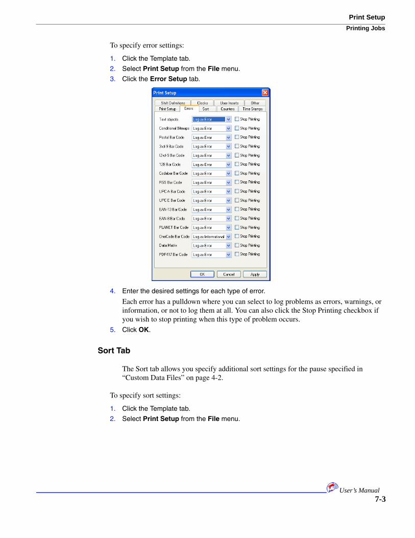
Print SetupPrinting Jobs
To specify error settings:
1. Click the Template tab.
2. Select Print Setup from the File menu.
3. Click the Error Setup tab.
4. Enter the desired settings for each type of error.
Each error has a pulldown where you can select to log problems as errors, warnings, or information, or not to log them at all. You can also click the Stop Printing checkbox if you wish to stop printing when this type of problem occurs.
5. Click OK.
Sort Tab
The Sort tab allows you specify additional sort settings for the pause specified in “Custom Data Files” on page 4-2.
To specify sort settings:
1. Click the Template tab.
2. Select Print Setup from the File menu.
7-3User’s Manual

Print Setup
Printing Jobs
3. Click the Sort tab.
4. Enter the desired criteria.
Enter the amount of space the delay will take on the conveyer. Enter the seconds of the pulse sent and the number of pieces the pause will offset.
Counters Tab
The Counters tab allows you to create the Counters that are applied in text properties. See “Counter” on page 5-18.
To specify counters:
1. Click the Template tab.
2. Select Print Setup from the File menu.
7-4User’s Manual

Print SetupPrinting Jobs
3. Click the Counters tab.
4. Click the Add button.
The Counter Definition window appears.
7-5User’s Manual

Print Setup
Printing Jobs
5. Enter the counter Name.
6. Select the counter Type.
You can choose Record, Piece or Custom. The custom values are described here as the others are subsets of Custom.
Enter the Counter values and what to do if overflow occurs. Decide if counters should reset when printing starts
For all types enter the [pad character and length and whether the pad is formatted for the region. Select the character set. This setting usually remains Numeric.
7. Click OK.
The counter is added to the counters table.
Time Stamps Tab
The Time Stamps tab allows you to create the Time Stamps that are applied in text properties. See “Time Stamp” on page 5-18.
Note: Clocks should be defined prior to defining Time Stamps.
To specify time stamps:
1. Click the Template tab.
2. Select Print Setup from the File menu.
3. Click the Time Stamps tab.
4. Click the Add button.
7-6User’s Manual

Print SetupPrinting Jobs
The Time Stamp window appears.
5. Enter the Counter name and description.
6. Select the Clock.
Clocks are created via the Clocks tab. Clocks must be created before Time Stamps.7. Select the type of time stamp to insert and click Insert.
The definition field is populated. You may change the definition is desired.8. Click OK.
The counter is added to the counters table.
Shift Definitions Tab
The Shift Definitions tab allows you to create the shift definitions that are applied in text properties. See “Shift Code” on page 5-20.
Note: Clocks should be defined prior to creating Shift Definitions.
To specify shift definitions:
1. Click the Template tab.
2. Select Print Setup from the File menu.
7-7User’s Manual

Print Setup
Printing Jobs
3. Click the Shift Definition tab.
4. Click the Add button.
The Shift Definition window appears.
5. Enter the shift name and description.
6. Select the Clock.
Clocks are created via the Clocks tab. Clocks must be created before shift definitions.
7. Click Add/Edit.
7-8User’s Manual

Print SetupPrinting Jobs
A new window appears.
8. Enter the start time and code for the shift.
9. Click OK.
These are entered in the shifts table.10. Click OK.
The shift is added to the shift definitions table.
Clocks Tab
The Clocks tab allows you to create the Clocks that are applied in text properties as well as used to create time stamps and shift definitions.
To specify clocks:
1. Click the Template tab.
2. Select Print Setup from the File menu.
3. Click the Clocks tab.
4. Click the Add button.
7-9User’s Manual
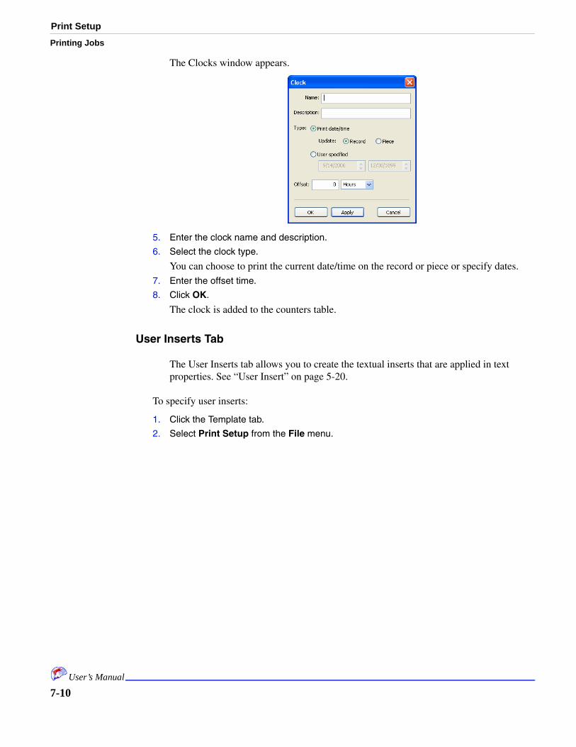
Print Setup
Printing Jobs
The Clocks window appears.
5. Enter the clock name and description.
6. Select the clock type.
You can choose to print the current date/time on the record or piece or specify dates.7. Enter the offset time.
8. Click OK.
The clock is added to the counters table.
User Inserts Tab
The User Inserts tab allows you to create the textual inserts that are applied in text properties. See “User Insert” on page 5-20.
To specify user inserts:
1. Click the Template tab.
2. Select Print Setup from the File menu.
7-10User’s Manual

Print SetupPrinting Jobs
3. Click the User Inserts tab.
4. Click the Add button.
The User Inserts Definition window appears.
5. Enter the insert name and description.
6. Enter the prompt that users will see to enter this insert.
7. Enter the default value.
8. Click OK.
The insert is added to the inserts table.
Other
The Other tab is used for troubleshooting. It simulates the encoder or sensor to help identify encoder or sensor problems.
7-11User’s Manual

Checking Ink Levels
Printing Jobs
To simulate the encoder or sensor:
1. Click the Template tab.
2. Select Print Setup from the File menu.
3. Click the Other tab.
4. Check the boxes to simulate the encoder and/or sensor.
5. Enter the desired simulation parameters.
6. Click OK.
Checking Ink Levels
It is advisable to check ink levels before and during printing. You can also look at ink usage statistics.
To check ink levels:
1. Click the Template tab.
7-12User’s Manual

Printing From the Job TabPrinting Jobs
2. Select Ink Levels from the View menu.
3. View the levels.
4. Click the exit icon (X) on your window to close it.
To check ink usage:
1. Click the Template tab.
2. Select Ink Usage from the View menu.
3. View the levels.
4. Click the exit icon (X) on your window to close it.
Printing From the Job Tab
After the following items have been completed you are ready to print the job:
• Data imported• Template• Print Setup• System Setup• Physical table top alignment
To print the job:
1. Click the Job tab.
2. Enter the print parameters.
These include start piece and stop piece numbers, how many times you want each record printed, and whether you want to print test patterns first.
7-13User’s Manual

Checking Print Status
Printing Jobs
3. Click Print.
Note: When you are printing a job, all items in all menus become unavailable except Stop Printing.
Checking Print Status
The Job window displays a variety of print status information. You can see the current record number being printed, how many pieces per hour are printing, the conveyer speed, and log information. Log information is displayed in the log window and is color coded:
Color Definition
Black Information only
Blue Warning
Red Error
7-14User’s Manual

Checking Print StatusPrinting Jobs
Changing Print Status Display
This window displays current printing status in the Print Status pane. It displays the conveyer speed in the status bar. In both cases you can click on the type of information displayed.
To change print status displayed:
1. Click the Job tab.
2. Click the type of status displayed in the Print Status pane.
7-15User’s Manual

Checking Print Status
Printing Jobs
For example, if the status currently displays pieces per hour, click this to change to seconds or minutes. You can toggle through the selections.
To change conveyer status displayed:
1. Click the Job tab.
2. Click the type of conveyer status displayed in the status bar.
For example, if the status currently displays ft./hour, click this to change to seconds or minutes or even centimeters. You can toggle through the selections.
7-16User’s Manual

Checking Print StatusPrinting Jobs
Note: If the conveyer speed becomes too fast, the conveyer speed status turns red and then an error dialog appears.
7-17User’s Manual

Reprints
Printing Jobs
Viewing the Job Log
The job log displays a variety of information while the job prints. Error are shown in red and described in “Error Codes” on page 8-11. Blue items indicate warnings and black is informational.
Reprints
While you are printing you may notice errors. When you notice errors, you can use the find options in the data fields to locate records which need to be reprinted.
To locate and reprint records:
1. Click the Data tab.
2. Use the Find feature to locate the desired record.
See “Finding Records” on page 4-5.
7-18User’s Manual

ReprintsPrinting Jobs
3. Right-click the row and select Add to Reprints.
You can also click the Add to Reprints button in the Find window. The selected rows are highlighted green.
4. Repeat steps 3 and 3 until all reprints are marked.
5. Click the Job tab.
6. Check the Reprint box.
7. Click Print.
The records are reprinted.8. Click the Data tab.
9. Right-click anywhere in the data table and select Clear Reprints.
10. Click the Job tab.
11. Uncheck the Reprint box.
7-19User’s Manual

Reprints
Printing Jobs
7-20User’s Manual

Chapter 8: Troubleshooting
In This Chapter
• Reprogramming Boards
• Calibrating
• Pulse-Spitting
• Smart-Spitting
• Pulse-Warming
• Print inBlank Pages
• Unrecogized Fonts
• File Control Settings
• Ink Bleeding on Barcodes
• Error Codes
• Warnings
The following sections can help your troubleshoot printing problems. The troubleshooting table below can help you identify common problems.
Reprogramming Boards
This feature is accessible from the File menu when the Job tab is selected. It is used when a new software version renders a board obsolete. Use this option only when you have been notified to do so.
Problem Possible Cause Action
Blank pages printing
Paper size doesn’t match print size
See “Printing Blank Pages” on page 8-8.
Boards not operating properly
New software version has been uploaded
See “Reprogramming Boards” on page 8-1.
Files created on another machine unable to open
Files settings need adjustment
See “File Control Settings” on page 8-9
Fonts not printing or font error message
Fonts are unrecognized
See “Unrecognized Fonts” on page 8-9
Gaps Calibration errors See “Calibrating Encoder Ticks per Inch, Pen Spacing, Head Distances” on page 8-2.
Ink bleeding Pixel width for ink dispensing is too high
See “Ink Bleeding on Barcodes” on page 8-10.
Ink not dispensing correctly. Missed sections.
Dried or cold ink in heads
See “Pulse-Spitting Implementation” on page 8-5 and “Pulse-Warming Implementation” on page 8-7 and “Smart-Spitting Implementation” on page 8-6.
Items not aligned Calibration errors See “Calibrating Encoder Ticks per Inch, Pen Spacing, Head Distances” on page 8-2.
No sort pulse Slot 1 is inactive See “Firewire Hookup” on page 9-1.
Overlaps Calibration errors See “Calibrating Encoder Ticks per Inch, Pen Spacing, Head Distances” on page 8-2.
Path not recognized
Files settings need adjustment
See “File Control Settings” on page 8-9
8-1

Calibrating Encoder Ticks per Inch, Pen Spacing,
Troubleshooting
Calibrating Encoder Ticks per Inch, Pen Spacing, Head Distances
You should print some test pages and review them for proper alignment. If you find that items printed are not properly aligned, perform the following procedure:
1. Print a test pattern from the inkjet software to see if there are gaps or overlaps of the pens within the head.
If so, it usually means that one side of your cross-piece mounting bracket needs to be adjusted to the right or to the left. This will close or open the gap between pens. (Gaps and overlaps examples are below.)
2. With your software closed, right-click on the Array Software icon on your desktop and select Properties.
The Properties window appears.
3. Click Find Target.
This opens the folder where your configuration files reside.
Overlapped PensProperly Aligned Pens
Pens with Gaps
8-2User’s Manual

Calibrating Encoder Ticks per Inch, Pen Spacing, Head Dis-Troubleshooting
4. Locate setup.cfg and open it with Notepad or Wordpad.
The first few lines of the document look like this:[System]PostalBarcodeType=Postnet (Postnet, aus-4-State, jpn-4-state)DefaultFileType=1upformat (csv, 1upformat, scitex, text1, text2,
DebugShowImage=0DebugSaveBitmap=0FieldReserved=$EncoderTicksPerInch=303PenSpacing=303
5. Change the values for Encoder.Ticks and Pen.Spacing to equal 300.
Be sure to write down the previous values just in case you need to change back.EncoderTicksPerInch=300PenSpacing=300
6. Save your changes.
Keep this file open, because you will go back to it later. Make sure your changes are saved – they must be saved to take effect in the software.
7. Start Array Imaging System Software.
8. Click the Template tab.
9. On a blank template, create a large rectangle object on any head on the template:
The easiest way is to place an Indicia object on the template and manually enter its width and height in the object’s Properties General Tab (remember to uncheck Force Square). Roughly center the box horizontally and vertically on the template for the head.
For a 2 inch head a 7 inch wide by 1.5 inch tall Indicia on an 8.5 by 11 piece works well. The wider the width of the box the more accurate the derived values will be.
Note: Use as wide a box as the piece you are running through allows.
10. Save this template.
11. Print a piece and measure the actual printed width of the box (outside edge to outside edge).
Ideally, the box will be 7 inches wide if the encoder is generating exactly 300 ticks per inch. If the actual width is not 7 inches then the measured width can be used to calculate the true encoder-ticks-per-inch using a simple ratio:Encoder ticks per inch = (desired width / actual width) x 300
For example, if the actual printed box is 7.125 inches wide:Encoder ticks per inch = (7.000 / 7.125) x 300Encoder ticks per inch = 0.9824 x 300Encoder ticks per inch = 294.72
12. Enter the value calculated in step 11 for the “EncoderTicksPerInch” and “PenSpacing” settings in the setup.cfg file.
Round the value off to the nearest integer (294.72 -> 295). 13. Save the changes, and open up the Array Imaging System Software again.
14. Print another 7 by 1.5 inch box to see the effect.
15. Restart Array Imaging System Software.
The changes will not take effect unless the software is re-started.
8-3User’s Manual

Calibrating Encoder Ticks per Inch, Pen Spacing,
Troubleshooting
Note: Changing these values will NOT affect the printed width of the box. The box will always measure 7.125 inches regardless of values entered. Nothing can be done to correct that except to make the encoder generate exactly 300 ticks per inch. This is because the image is always rendered at 600 DPI regardless of these settings. These settings are used only to generate the proper distance for each pen's offset from sensor and the left and right nozzles on each pen's face. They still play a crucial role in print quality and printing across pen boundaries.
Note also that although the box width will not change, its position on the printed piece will. This is because these settings are used to determine how many encoder ticks per inch there are for sensor offsets as well.
This is why this step should be done BEFORE determining the exact Distance from Sensor settings in the System Setup. See “System Setup” on page 6-2.
Once the above value is entered in Setup.cfg for EncoderTicksPerInch and SensorOffset you should notice that the vertical sides of the printed box are better aligned across pen boundaries. There may still be a small stagger, but it should be minor. You can correct this minor offset by changing the “PenSpacing” setting in Setup.cfg for each pen. Increasing this setting will “pull” lower pen's print left, decreasing it will “push” lower pen's print to the right (assuming left-to-right transport).
A crucial point to remember is that if the stagger changes from one printed piece to the next and is not constant then it means the piece is slipping or the encoder is skipping on the belts etc. If this is true then the mechanical cause should be identified and eliminated before trying to compensate through software. If the mechanical transport and encoder are correct then the stagger should remain constant on all pieces and pens.
16. Once the pens are aligned as closely as possible, you may still need to adjust an individual pen or two. That can be done in the setup.cfg on the following lines:[Board1.Settings]PulseWidth=Pen1.SensorMarginAdjust=Pen2.SensorMarginAdjust=Pen3.SensorMarginAdjust=Pen4.SensorMarginAdjust=
Note: The values that are entered for each pen are measured in single pixels. For a left to right transport, positive number move the vertical line in your box to the left, and negative numbers will move the vertical line to the right. These values should usually be within 5 (+/-) of 0.
17. Once all the pens have been aligned, the Distance From Sensor setting in the System Settings should be set for each head. See “System Setup” on page 6-2.
The same “box” can be used for this purpose. Simply place the box on the template so its left edge is 1/2 inch from the left edge of the layout (manually enter into General Properties) and adjust the setting such that its printed position matches. Increasing the sensor distance moves the box to the left (because each pen waits more encoder ticks to print) and decreasing it will move the print right (assuming left-to-right transport).
8-4User’s Manual

Pulse-Spitting ImplementationTroubleshooting
Pulse-Spitting Implementation
Pulse-spitting is a method used to purge the pen head nozzles of any dried ink by actually firing drops of ink from the pen. Pulse-spitting used in addition to Pulse-warming provides a robust solution to print quality issues resulting from harsh ambient temperatures and/or printing with a pen that has been exposed to air for an extended period of time without firing. This explanation is extracted from Array Technologies, Inc. documentation.
Theory of Operation
Although the “Print Test-Pattern” option addresses the issue of poor print quality on the leading edge of the first printed piece, it does not solve the problem of extended pauses during printing. These pauses may result from feeder reloads, jam clearing, etc., and are unique because the user never clicks the “Stop” button; therefore, the Test-Pattern is not a viable solution.
The spit feature causes the printer to spit X pixels at a distance of Y encoder ticks before the piece if and only if the pen has not printed for the past Z seconds. The intent is that the spit drops miss the piece to be printed on – by being fired onto the transport, or into open air.
Note that spitting will never occur on the first piece after print commences (use Test-Pattern instead).
There are settings in the Setup.cfg file used to control the pulse-spitting parameters:
Spit.On=1Spit.TimeOut=15Spit.NumberOfPixels=25Spit.Gap=300Spit.On (default = 1):1 = Spitting function is enabled0 = Spitting function is disabledSpit.Timeout (default = 15):
Spit trigger time-out in seconds. Only spit before the next piece if the pen has not printed for this many seconds. The time measurement is made per pen since its last drop was fired.
Spit.NumberOfPixels is the number of full-black strokes to fire when spitting occurs. The default is 25.
Spit.Gap is the distance (in encoder ticks) before the piece reaches the pen when spitting will occur. For example, if this setting is 300 (the default) and the Spit.NumberOfPixels is 25, then the spit will begin 325 encoder tics before the piece reaches the sensor (at 300 DPI).
8-5User’s Manual

Smart-Spitting Implementation
Troubleshooting
Smart-Spitting Implementation
Smart-spitting can be used to alleviate problems that are encountered when nozzles are infrequently fired. This may be encountered when printing descenders or “floating” barcodes. Smart-spitting should be used in conjunction with Pulse-spitting. This explanation is extracted from Array Technologies, Inc. documentation.
Theory of Operation:
Under normal printing conditions, ink is printed from each nozzle on each piece; a nozzle does not have the ability to dry/clog since it is continually printing. Problems arise when a jet nozzle is fired infrequently, i.e., it may clog if not fired often.
The Smart-spitting feature keeps a running count of pixels printed; when the pixel count falls below a threshold value, nozzles are fired.
There are five settings in Setup.cfg used to control Smart-spitting:
Mode=0 (0-off, 1-spread, 2-edge spread, 3-edge solid)Range=1,19TargetPixels=5CutOff=0Decay=0.75
These settings determine where the spitting occurs.
There is no default for the range. If the pixel count for this piece falls within this range, consider it for Smart-spitting. For example: for processing descenders, this value could be “1,50,” for processing floating bar codes, this value could be “50,2000.”.
TargetPixels is the number of pixels to print if necessary. Cutoff is the threshold value. When the running pixel count falls below this value, spitting will occur.
The decay setting is used to decrement/decay the running pixel count. At the end of each piece printed the pixel count for the current piece and is added the running pixel count, and multiplied by the Decay value.
Since multiple Smart-spitting settings/profiles may be needed (one for descenders, one for floating bar codes) each profile is stored in its own section in setup.cfg. For example:
Mode Setting Description
0 No spitting
1 The spitting is spread between the end of the last printed pixel on the piece and the edge of the piece.
2 The spitting is spread out along the edge of the piece
3 The spitting occurs at the edge of the piece
8-6User’s Manual

Pulse-Warming ImplementationTroubleshooting
[Spit.Descenders]
Note: Spitting occurs on the piece. If this is not desired, change the width of the piece in Print Setup.
Pulse-Warming Implementation
Pulse-warming is a method used to maintain the ink in the pen’s head at a constant temperature of 45 to 50 degrees Celsius. This helps maintain consistent print quality at varying ambient temperatures and minimizes nozzle clogging due to dried ink formed at the nozzle orifice. This explanation is extracted from Array Technologies, Inc. documentation.
There are settings in the Setup.cfg file used to control the pulse-warming parameters:
Warming.On=1Warming.Temperature=50Warming.AmbientTimeOut=20Warming.On (default = 1):
The warming function can be enabled (1) or disabled (0):
Warming.Temperature (default = 50):
Target head temperature (warming.temperature) is in degrees Celsius. This setting should be between 45 and 50 degrees (50 is default). Setting it too high could cause the pen to overheat and enter thermal shutdown. If this occurs printing will stop and an error will be reported.
Warming.AmbientTimeOut is the time (in minutes) used as a time-out to trigger recalibration of the head temperatures to ambient. Default is 20. If no printing has occurred for this amount of time when the user begins print, the software will assume the heads are at ambient temperature and recalibrate the target head temperature accordingly.
Note that the software automatically recalibrates all the pens’ target temperatures the first time the user prints after the application is started. The software also recalibrates individual pen(s) whenever a new (or different) pen is detected in any stall at print start.
Pulse-Warming Addendum
This section describes the possible problems that may result if pulse-warming is used incorrectly. It is extracted from Array Technologies, Inc. documentation.
For pulse-warming to work correctly, the software must have an accurate baseline “reference” reading for each pen. The target warming-point for each pen is calculated based on this reference reading. The reference reading must be made at a point when the pen’s nozzles are at ambient temperature (the same temperature as the printed circuit boards inside the RSI print-head).
8-7User’s Manual
Printing Blank Pages
Troubleshooting
The software automatically makes this reading based on either of two conditions:
1. If a new (or different) pen is detected in any stall since the last time printing was performed the software assumes the pen’s nozzles are at ambient temperature and recalculates the warming set-point for that pen.
2. If an amount of time greater than that specified in the setup.cfg parameter Warming.AmbientTimeOut elapses since “Stop” was pressed for any pen(s), the software assumes the pens’ nozzles are at ambient temperature and recalculates their warming set points.
These assumptions are safe for normal operating procedures. When “new” pens are inserted they typically have not been printed with recently. Also, if printing has not occurred for an extended period of time it is safe to assume the heads have cooled to ambient temperature.
Note: The pen nozzles cool relatively quickly: however, the temperature decays asymptotically. That is, the temperature may drop five degrees Celsius in ten seconds but may require five minutes to drop the last degree required to reach ambient temperature.
Problems can occur if a pen nozzles’ temperature is greater than ambient temperature when the software makes its baseline measurement. For example, if a pen’s nozzles are at 45 degrees Celsius when the software assumes they are at 25 degrees Celsius then the pen’s target set-point may incorrectly be set to 70 degrees Celsius when the desired target was 50 degrees Celsius. This would result in inferior print quality and may even cause the pen to overheat and enter thermal shutdown.
An example scenario would be “swapping pens.” That is, removing two or more pens from their stalls and placing them in different stalls. At the next print initiation the software will assume “new” pens were inserted and that they are at ambient temperature, and recalibrate their thermal set-points. Note that there is no way to reliably detect and track the swapped pens.
If thermal shutdown does occur, the software will cease printing with an error [06XXYYZZ] reported in the log but no damage will be done to the printer hardware. Simply cleaning the pens and waiting for them to cool to ambient should correct the problem.
Another side effect of pulse-warming is the fact pulses are being sent to the pens even when they are not printing. If warming is enabled, then whenever the transport is moving (encoder ticks are being generated) the pens are receiving energy pulses. This means that the accepted practice of removing/inserting pens while the transport is moving is now more hazardous since the mating pogo-pins may be shorted as a pen contact pad slides across them.
Printing Blank Pages
If your paper size does not match the actual piece size, you may see extra blank pages print or assume that every other page is printing. Make sure that the Paper Size setting in your Print Setup matches the actual size of the piece or less than how often your sensor triggers occur. If the page size is larger, the sensor will be missed and extra pages will print. This happens most often in a continuous form, but can also happen on a cut sheet job.
8-8User’s Manual
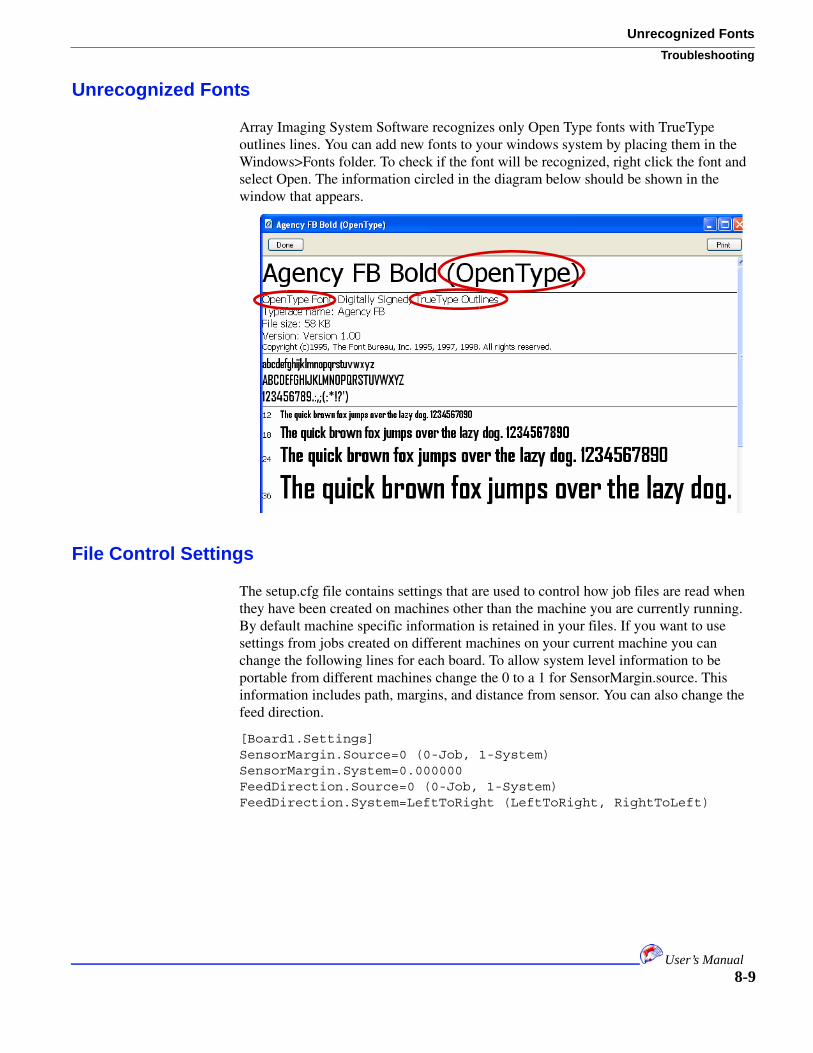
Unrecognized FontsTroubleshooting
Unrecognized Fonts
Array Imaging System Software recognizes only Open Type fonts with TrueType outlines lines. You can add new fonts to your windows system by placing them in the Windows>Fonts folder. To check if the font will be recognized, right click the font and select Open. The information circled in the diagram below should be shown in the window that appears.
File Control Settings
The setup.cfg file contains settings that are used to control how job files are read when they have been created on machines other than the machine you are currently running. By default machine specific information is retained in your files. If you want to use settings from jobs created on different machines on your current machine you can change the following lines for each board. To allow system level information to be portable from different machines change the 0 to a 1 for SensorMargin.source. This information includes path, margins, and distance from sensor. You can also change the feed direction.
[Board1.Settings]SensorMargin.Source=0 (0-Job, 1-System)SensorMargin.System=0.000000FeedDirection.Source=0 (0-Job, 1-System)FeedDirection.System=LeftToRight (LeftToRight, RightToLeft)
8-9User’s Manual

Ink Bleeding on Barcodes
Troubleshooting
Ink Bleeding on Barcodes
If the amount of ink dispensed is too dense, you may see ink bleeding in your bar codes. You can adjust the amount of ink dispensed to eliminate this issue. You modify the following lines in the setup.cfg file to reduce the amount of ink dispensed. The number is the amount, in pixel width, of ink dispensed.
BarCode.XwidthAdjust=0BarCode.WideWidthAdjust=0
8-10User’s Manual

Error CodesTroubleshooting
Error Codes
When calling MCS for help, please note the error code numbers you receive. These are helpful to us in tracking and evaluating your error.
==========================================================================[01 BB 00] - Print Error: Board X doesn't appear to be responding.EXT_ERR_NO_PEN_PARAMS / ERR_NO_RESPONSENo pen_params message received from board within 2 secs after print command sent==========================================================================[02 BB PP req_cnt] - Print Error: Board X doesn't appear to be responding.EXT_ERR_NO_REQUESTS / ERR_NO_RESPONSEDidn't see 2 image requests from pen after 4 secs since sending print command==========================================================================[03 BB PP 03] - Print Error: The PC was unable to generate images fast enough.EXT_ERR_IMAGE_Q_EMPTY / ERR_INVALID_PC_STATEPen's print_result=FW_ERR_IMAGE_UNDERFLOW (3)==========================================================================[04 BB PP] - Print Error: Board X doesn't appear to be responding.EXT_ERR_PEN_SYNC / ERR_NO_RESPONSE => [04 BB PP] pen's img reqs lag last pen's.Number of image_request msgs from pen > 1 behind “last pen”==========================================================================[05 BB PP prntResult] - Print Error: Internal error for board X.EXT_ERR_FIRMWARE / ERR_INVALID_FIRMWARE_STATEPen's print_result in image_req msg != 0 3 = img underflow (pc was unable to generate images fast enough) 4 = img overflow 5 = incorrect isoch tag in pld (obsolete) 6 = packet overflow 7 = dma unsync (obsolete) 8 = image unsync (img tag != previous+1)==========================================================================[06 BB PP dout bitfield] - Pen X (Board Y, Pen Z) has failed/stopped printing.EXT_ERR_PEN_FAILURE / ERR_PEN_FAILUREpen's image_req msg indicates pen dout error: 1 = warm 2 = hot 4 = underVoltage 8 = overVoltage 16 = rowShort 32 = colShort 64 = A/D done bit missing==========================================================================[07 EE 00 XX] - The PC Firewire card's capabilites are inadequate for the printer.EXT_ERR_FIREWIRE_FAILURE / ERR_INVALID_PC_STATE / WM_PC_ERROREE = bitfield of errors: 1 = Not isoch resource manager capable 2 = Not cycle master capable 4 = Does not support isoch operations 8 = Not bus manager capable 16 = max async write request < 512 (see XX for actual num) 32 = max async read request < 512 (see XX for actual num)==========================================================================
8-11User’s Manual

Warnings
Troubleshooting
Warnings==========================================================================[01BB00XX] - Print Warning: Board BB failed to contact head.XX = observed pen-driver-board's asic id(asicTotal==0)||(asicTotal>(0x80*4))==========================================================================[02BBPPXX] - Print Warning: Board BB to Pen PP interface failed.XX = observed pen-driver-board's asic id(asicId==0)||(asicid>0x80)==========================================================================[03BBPP] - Print Warning: Board BB, Pen PP - no pen in stallpenId.bits.serialNumber == 0x3fff
8-12User’s Manual

Chapter 9: Hardware Installation
In This Chapter
• Firewire
• Rack Firewire Hookup
• New Head Hookup Procedure
• Daisy-chaining Controllers
This section contains information about installing or replacing hardware items related to the Array Imaging System Software application.
Firewire Hookup
This section describes the firewire hookup requirements from the PC to one or more formatter boards and its relationship to board number and the sort output pulse.
The formatter boards obtain their Board Number (as reported in the Application’s Log Window on power-up) by their position in the firewire daisy-chain from the PC to the formatter boards.
The board number assigned to each formatter board determines what data its corresponding head will print. Board 1 should be connected to the head closest to the sensor with each successive board being connected to the next farthest head from the sensor.
Although it may seem irrelevant which board is assigned any given board number, the problem is that only the formatter board in slot 0 (the slot closest to the side of the controller) of the rack can control the sort output. This presents a problem only when the user sets one or more boards Inactive in System Setup. If the board in slot 0 is inactive then no sort pulses will be generated by the unit. If the firewire is daisy-chained such that board 1 is NOT in slot 0 then disabling boards 2, 3, and 4 results in no active board in slot 0, hence no sort pulse.
Rack Firewire Hook-up
The following procedure attaches the firewire cards to the boards.
1. Identify Rack slot 0.
Slot 0 is the slot closest to the side of the controller and furthest from the power-supply in the rack.
2. Connect the first firewire from the PC’s firewire card to the board in slot 0 (this will be board 1).
3. Connect a 6” jumper firewire from the board in slot 0 to the board in slot 1 (this will be board 2).
9-1

New Head-hookup Procedure
Hardware Installation
4. Connect a 6” jumper firewire from the board in slot 1 to the board in slot 2 (this will be board 3).
5. Connect a 6” jumper firewire from the board in slot 2 to the board in slot 3 (this will be board 4).
Small Enclosure Firewire Hook-up
1. Identify board 1.
On 4” small enclosure units (two formatter boards) board 1 is the board furthest away from the edge of the unit (inner-most formatter board). On 2” small enclosure units (one formatter board) it is not an issue.
2. Connect the first firewire from the PC’s firewire card to board 1.
3. Connect a 6” jumper firewire from board 1 to board 2.
When daisy-chaining racks or small enclosures follow the same procedure for the first unit and substitute the last formatter board in that unit for the PC for instructions on hooking up the remaining units. Note that “board 1” in each unit will generate sort pulses if wired correctly.
Note that systems that have been working properly since their initial installation can fail to operate properly when you switch from a software version.
New Head-hookup Procedure
For rack systems, the “first” formatter board must be connected to the head closest to the sensor and the remaining formatter boards should be connected to heads increasing in distance from the sensor.
For the small enclosure units the fire-wire daisy chain determines the board order. The fire-wire starts with the PC and connects to board 1; the fire-wire leaves board 1 and is connected to board 2, etc. The rule that the head closest to the sensor must be connected to board 1 is still true; however, board 1 is now defined as the board connected to the PC as opposed to being the “first” board in the rack.
Daisy-chaining Controllers
Daisy-chaining units is defined as using two or more units to make-up one “system.” For example a 4" small enclosure unit can be daisy-chained with a 2" small enclosure unit to make a 6" system. This is accomplished by daisy-chaining the fire-wire from the PC to unit 1 - board 1, then unit 1 - board 2, then unit 2 - board 1. The encoder and sensor are daisy-chained with a special DB9-to-DB9 ribbon cable provided by Array Technologies. This cable allows the encoder and sensor to be connected to unit 1 only. The cable feeds the encoder and sensor from unit 1 to unit 2. There is currently no limit to how many units can be daisy-chained other than the total print area cannot exceed 14" and a different encoder/sensor daisy-chain cable is required for each number of units (the cable for daisy-chaining two units will not work for daisy-chaining three units, etc.).
9-2User’s Manual

Hardware Installation
Note also that the AC power can also be daisy-chained to multiple units such that the power-switch on unit 1 will control AC power to all other daisy-chained units. This is accomplished with a special “female-to-male” AC cord (available from Array Technologies) and leaving the power-switch in the “ON” position for all units except the first unit - which now controls the power for all.
9-3User’s Manual

Hardware Installation
9-4User’s Manual

Index
Numerics
1 Up format 4-2
A
aborted wizard 2-4
About 1-1
add to reprints 7-19
align 5-22
Attaching 5-24
attachment type 5-24
audience 1-1
avoid pen boundaries 5-22
B
Barcodes 5-14
Postal 5-16
standard 5-15
Bitmaps 5-11
conditional 5-12
unconditional 5-11
Black 7-14
blank pages 8-8
Bleeding 8-10
Blue 7-14
board settings 6-3
C
CD 1-1
change pen settings 6-5
clear reprints 7-19
Clocks tab 7-9
Code Page 4-4
colors 5-26
conditional
bitmaps 5-12
Conditional Message Lines 5-9
conventions 1-1
copy 5-22
Counters 5-18
Counters Tab 7-4
CSV 4-2
Ctrl-Alt-1 1-1
Ctrl-Alt-2 1-1
Custom 4-2
custom data files 4-2
customize 3-5
D
daisy-chaining controllers 9-2
data 4-1
data entry font 3-5
data file options 4-1
data font 4-7
data source type 4-3
data tab 3-4
Database 4-2
database parameters selection statement 4-3
Defined File Types 4-1
delete 5-22
description
data type 4-4
device driver 2-2, 2-3
Display Area 3-3
display area 3-3
distance between head boards 5-3
Distance From Sensor 6-3
distance from sensor 8-9
Distance From Top Of Piece 6-3
dock markers 5-26
Docking 5-23
document structure 1-1
dongle 2-3
duplicate 5-22
E
editing options 5-21
Encoder Ticks 8-2
error codes 8-11
error tab 7-2
F
Feed Direction 6-4, 7-2
field headers 4-7
File Format Detail window 4-1
I-1

file menu
data file options 4-1
find
scan data 5-26
find records 4-5
find window 4-6
firewire hookup 9-1
firmware 2-3
font menu 3-5
fonts
unrecognized 8-9
H
hardware 9-1
head board 5-3
Head Distances 8-2
heads
new 9-1, 9-2
help 1-1
I
import data 4-1
Indicia 5-10
Ink 8-10
ink dispensed 8-10
ink levels 7-12
ink usage 7-13
installation 2-1, 2-3
hardware 9-1
interface 3-1
J
job
new 6-2
open 6-1
print 7-1
save 6-2
job log 7-18
Job tab 3-4
print 7-13
Jobs 6-1
L
largest field 5-26
layering 5-25
log tab 3-4
longest field 5-26
M
main window 3-2
margins 8-9
menu
view 3-5
Menu Bar 3-3
Message Lines 5-8
conditional 5-9
move 5-22
Move to Front/Push to Back 5-25
move to print areas 5-23
Move Up/Down 5-25
N
new
job 6-2
template 5-2
new items 5-3
new record block 5-4
O
Object Properties 5-22
OneCode 5-15
open 3-1
data files 4-4
job 6-1
template 5-1
open application 3-1
options 3-6
editing 5-21
Other tab 7-11
P
Paper orientation 7-2
Paper size 7-2
path 8-9
pen alignment 8-2
pen board 5-3
pen boundaries 5-22
Pen Settings 6-4
I-2
User’s Manual

change 6-5
Pen Spacing 8-2
Pen1.SensorAdjustMethod 6-4
Postal Barcode 5-16
Postal Barcode Description 4-4
postal barcodes
validate 4-6
Print 7-13
blank pages 8-8
jobs 7-1
proof 5-26
print areas 5-23
Print Orientation 7-2
Print Resolution 7-2
print setup 7-1
print status 7-14
change display 7-15
proof 5-26
properties 5-22
Pulse-spitting 8-5
pulse-splitting implementation 9-2
Pulse-warming 8-7
Q
Quick Add/Update 5-13
R
record blocks 5-4
Record Description 4-3
records
find 4-5
start 4-6
stop 4-6
view 4-5
Red 7-14
reprint 7-18
reprogramming boards 8-1
rotate 5-22
S
save
job 6-2
template 5-1
scan data 5-26
SCITEX 4-2
see gridlines 5-26
select objects 5-21
set a grid 5-26
Set Background 5-25
setup
print 7-1
system 6-2
setup.cfg 6-4
Shift codes 5-20
Shift Definitions tab 7-7
show anchor points, 5-26
show attachments 5-26
Show Background Image 5-25
show pen colors 5-26
show record data 5-4
show Z-order 5-26
Smart-spitting 8-6
software 2-1
Sort description 4-4
sort tab 7-3
splash screen 3-1
Standard Barcode 5-15
start records 4-6
Status Bar 3-4
status bar 3-4
stop records 4-6
system settings 8-9
system setup 6-2
T
tab selection area 3-4
tabs 3-4
data 3-4
job 3-4
log 3-4
template 3-4
template display area 5-3
Template orientation 7-2
Template tab 3-4
Templates 5-1
templates
display area 5-3
new 5-2
new items 5-3
open 5-1
I-3User’s Manual

record blocks 5-4
save 5-1
setup 5-2
Text I 4-2
Text II 4-2
text tab 5-5
Time Stamps 5-18
Time Stamps tab 7-6
Title Bar 3-2
Toolbar 3-3
transparent 5-7
troubleshooting 8-1
U
Unconditional bitmaps 5-11
unrecognized Fonts 8-9
unrecognized fonts 8-9
User Inserts 5-20
User Inserts tab 7-10
V
validate
postal bar codes 4-6
Variable 4-2
view
boards 6-3
options 5-26
pens 6-5
view menu 3-5
customize 3-5
data entry font 3-5
options 3-6
viewing records 4-5
W
warnings 8-12
wizard aborted 2-4
Z
zoom level 5-26
I-4
User’s Manual