
ARRANCADOR OLEOHIDRÁULICO...
15
ARRANCADOR OLEOHIDRÁULICO “START-HIDRO” MANUAL DE UTILIZACIÓN Y MANTENIMIENTO OLEOHIDRAULIC STARTER “START-HIDRO” OPERATION AND MAINTENANCE MANUAL Rev. 07 (04-2013) Fabricado por / Manufactured by : HIDRACAR S.A. • Pol. Ind. Les Vives – c/ Anaïs Nin, 14 08295 Sant Vicenç de Castellet, Barcelona (SPAIN) www.hidracar.com • E-mail: [email protected] • Tel.: +34 93 833 02 52 Fax: +34 93 833 19 50
Transcript of ARRANCADOR OLEOHIDRÁULICO...

ARRANCADOR OLEOHIDR ÁULICO “START -HIDRO”
MANUAL DE UTILIZACIÓN Y MANTENIMIENTO
OLEOHIDRAULIC STARTER “START -HIDRO”
OPERATION AND MAINTENANCE MANUAL
Rev. 07 (04-2013)
Fabricado por / Manufactured by :
HIDRACAR S.A. • Pol. Ind. Les Vives – c/ Anaïs Nin, 14 08295 Sant Vicenç de Castellet, Barcelona (SPAIN)
www.hidracar.com • E-mail: [email protected] • Tel.: +34 93 833 02 52 Fax: +34 93 833 19 50
2
MANUAL DE UTILIZACIÓN Y MANTENIMIENTO ÍNDICE : I ) PUESTA EN MARCHA Y ESQUEMA DEL CIRCUITO. II ) INSTRUCCIONES DE MANTENIMIENTO. III ) DIAGNÓSTICO DE AVERÍAS.
I ) PUESTA EN MARCHA Y ESQUEMA DEL CIRCUITO
1.- Comprobar que el nivel de aceite en el depósito este cubriendo la mirilla de nivel
superior.
NOTA: Cada vez que se utiliza el arrancador, se emplea una pequeña cantidad de aceite para la lubricación del conjunto interno del arrancador (Cuando el nivel de aceite en el depósito alcance la mirilla inferior indicadora de nivel, volver a llenar el depósito hasta el nivel superior. Utilizar siempre el mismo tipo de aceite procurando que esté completamente limpio y filtrado).
El aceite a utilizar tiene que ser del tipo hidráulico de viscosidad media 4,5 °E con un índice de 120 o superior, norma D2270 ASTM.
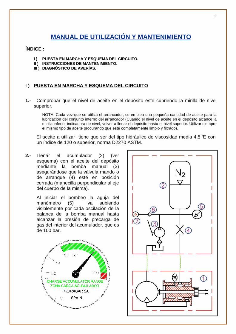
2.- Llenar el acumulador (2) (ver
esquema) con el aceite del depósito mediante la bomba manual (3) asegurándose que la válvula mando o de arranque (4) esté en posición cerrada (manecilla perpendicular al eje del cuerpo de la misma).
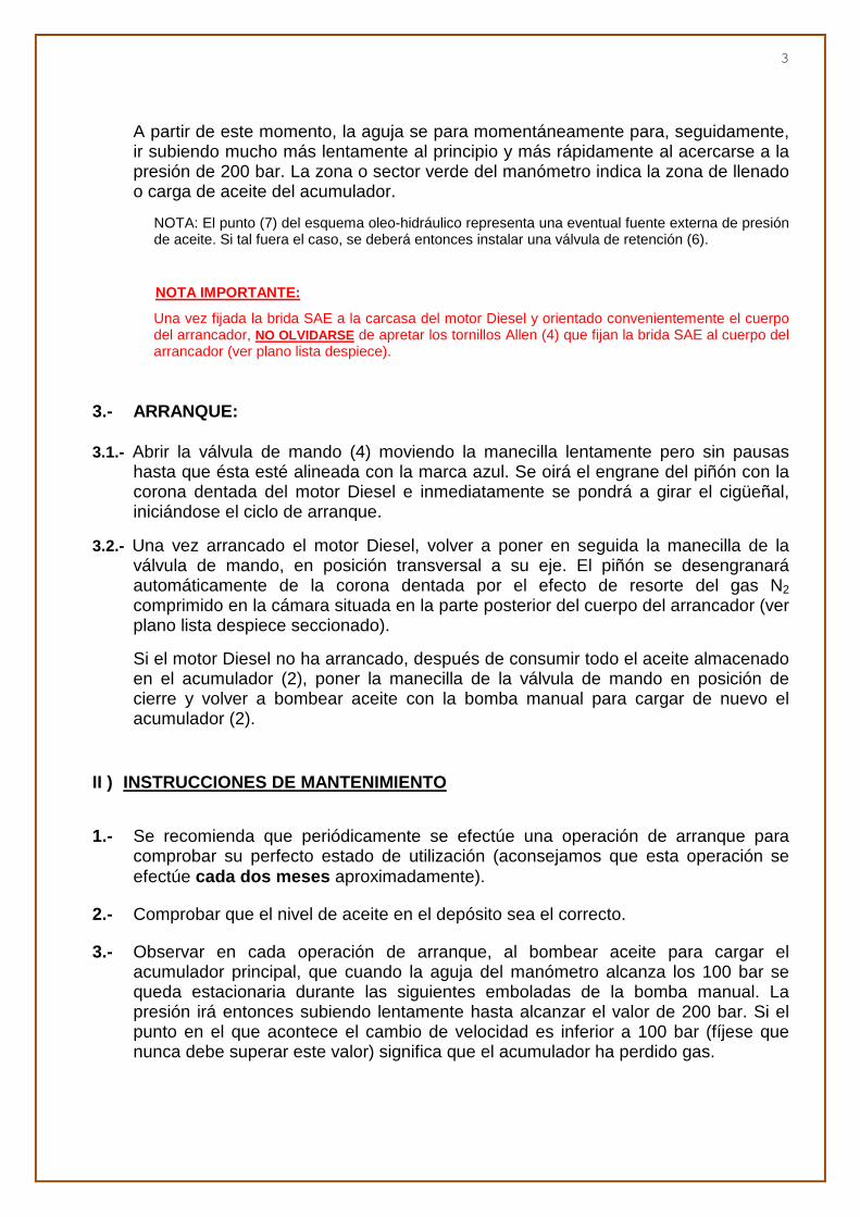
Al iniciar el bombeo la aguja del manómetro (5) va subiendo visiblemente por cada oscilación de la palanca de la bomba manual hasta alcanzar la presión de precarga de gas del interior del acumulador, que es de 100 bar.
3
A partir de este momento, la aguja se para momentáneamente para, seguidamente, ir subiendo mucho más lentamente al principio y más rápidamente al acercarse a la presión de 200 bar. La zona o sector verde del manómetro indica la zona de llenado o carga de aceite del acumulador.
NOTA: El punto (7) del esquema oleo-hidráulico representa una eventual fuente externa de presión de aceite. Si tal fuera el caso, se deberá entonces instalar una válvula de retención (6).
ANOTA IMPORTANTE:
Una vez fijada la brida SAE a la carcasa del motor Diesel y orientado convenientemente el cuerpo del arrancador, NO OLVIDARSE de apretar los tornillos Allen (4) que fijan la brida SAE al cuerpo del arrancador (ver plano lista despiece).
3.- ARRANQUE: 3.1.- Abrir la válvula de mando (4) moviendo la manecilla lentamente pero sin pausas
hasta que ésta esté alineada con la marca azul. Se oirá el engrane del piñón con la corona dentada del motor Diesel e inmediatamente se pondrá a girar el cigüeñal, iniciándose el ciclo de arranque.
3.2.- Una vez arrancado el motor Diesel, volver a poner en seguida la manecilla de la válvula de mando, en posición transversal a su eje. El piñón se desengranará automáticamente de la corona dentada por el efecto de resorte del gas N2 comprimido en la cámara situada en la parte posterior del cuerpo del arrancador (ver plano lista despiece seccionado).
Si el motor Diesel no ha arrancado, después de consumir todo el aceite almacenado en el acumulador (2), poner la manecilla de la válvula de mando en posición de cierre y volver a bombear aceite con la bomba manual para cargar de nuevo el acumulador (2).
II ) INSTRUCCIONES DE MANTENIMIENTO
1.- Se recomienda que periódicamente se efectúe una operación de arranque para
comprobar su perfecto estado de utilización (aconsejamos que esta operación se efectúe cada dos meses aproximadamente).
2.- Comprobar que el nivel de aceite en el depósito sea el correcto. 3.- Observar en cada operación de arranque, al bombear aceite para cargar el
acumulador principal, que cuando la aguja del manómetro alcanza los 100 bar se queda estacionaria durante las siguientes emboladas de la bomba manual. La presión irá entonces subiendo lentamente hasta alcanzar el valor de 200 bar. Si el punto en el que acontece el cambio de velocidad es inferior a 100 bar (fíjese que nunca debe superar este valor) significa que el acumulador ha perdido gas.

4
III ) DIAGNÓSTICO DE AVERÍAS
ATENCIÓN : Para evitar posibles daños personales, antes de desmontar cualquier elemento del conjunto del arrancador, DEBE VACIARSE TODO EL ACEITE A PRESIÓN QUE PUEDA HABER EN EL ACUMULADOR OLEO-HIDRÁULICO. Una vez hecho esto, tener en cuenta que el acumulador posee gas (Nitrógeno) a una presión de 100 bar en su interior, y que el cuerpo del arrancador también tiene una presión de N2 de valor variable según el modelo de arrancador.
1.- LA BOMBA MANUAL O LA ACCIONADA POR EL MOTOR NO DAN PRESIÓN: 1.1.- Causa posible: Aire u otras sustancias, suciedad u objetos extraños obturando las
tuberías que comunican las bombas con el acumulador.
Solución: Purgar las tuberías hasta la entrada al acumulador. Verificar posible obturación de tuberías y despejarlas con aire comprimido.
1.2.- Controlar la tensión de la correa de transmisión de accionamiento de la bomba (si existe ésta).
1.3.- Causa posible: Aspiración de la bomba obturada.
Solución: Desmontar y limpiar.
1.4.- Causa posible: La válvula de descarga, cuando hay instalada una bomba accionada por el motor, pierde aceite re-circulando éste al depósito.
Solución: Verificar que el resorte de cierre no esté ablandado o que la tuerca de compresión del mismo no esté floja. Verificar la posible presencia de suciedad en el asiento de cierre de la válvula (en circuitos con sólo bomba manual, esta válvula no se instala).
1.5.- Verificar que la válvula (4) no tenga fugas.
2.- PRESIÓN INSUFICIENTE EN EL SISTEMA: 2.1.- Causa posible: Válvula de descarga tarada demasiado baja.
Solución: Ajustar la tuerca de compresión del muelle de tarado hasta la presión deseada (en circuitos con solo bomba manual, esta válvula no se instala).
2.2.- Causa posible: Bajo nivel de aceite en el depósito.
Solución: Añadir la cantidad suficiente.
2.3.- Verificar estado del manómetro. Si está averiado o da lectura falsa, cambiarlo.
2.4.- Comprobar que la manecilla de la válvula de mando (4) está en su correcta posición de “Carga del acumulador”.
3.- EL PIÑÓN BENDIX GIRA LENTO O NO GIRA: 3.0.- El acumulador está sin presión de gas o la presión existente es insuficiente.
La presión de carga inicial de gas (Nitrógeno seco) es de 100 bar. Al iniciar el bombeo de aceite con la bomba manual se detecta la presión real de carga de gas. Basta observar la aguja del manómetro, ésta va subiendo visiblemente a cada movimiento de la palanca de la bomba manual. Cuando la presión de aceite iguala a la presión del gas del interior del acumulador la aguja del manómetro se para

5
aunque se continúe accionando la palanca de la bomba manual. Posteriormente la aguja del manómetro va subiendo al seguir bombeando aceite con la palanca de la bomba manual.
Si el acumulador a perdido parte de la presión inicial del gas, estando ésta por debajo de 70 bar, desmontar el acumulador SIGUIENDO MUY ATENTAMENTE LAS INSTRUCCIONES DE DESMONTAJE . (solicitarlas a HIDRACAR S.A. Fax 34 9383301950).
Proceder a cambiar las juntas del pistón y cargar con NITRÓGENO SECO con el conjunto de carga y llenado original (solicitarlo a HIDRACAR S.A. Si lo desea, puede enviarlo a HIDRACAR S.A. para su revisión y llenado hasta 100 bar
3.1.- Causa posible: Aceite excesivamente viscoso.
Solucion: Utilizar aceites para circuitos oleo-hidráulicos de 4,5 °E a 50 °C y de índice de viscosidad >120 (el aceite debe ser compatible con el caucho nitrilo).
3.2.- Causa posible: Aceite del motor Diesel excesivamente viscoso. Solución: Cambiarlo por el de viscosidad adecuada. Referirse a las especificaciones del fabricante del motor.
3.3.- Causa posible: Válvula de mando abierta parcialmente.
Solución: Asegurarse que la posición de la palanca esté en posición correcta y abra correctamente.
3.4.- Causa posible: Tubería de acumulador a motor oleo-hidráulico de arrastre del piñón Bendix restringida.
Solución: Verificar que el paso de la tubería de presión sea de diámetro nominal igual o superior al de salida de la válvula de mando (4) y que ésta no esté parcialmente obstruida.
3.5.- Causa posible: Fugas internas excesivas en el interior del motor oleo-hidráulico de arranque.
Solución: Desmontar el motor oleo-hidráulico y enviarlo a HIDRACAR S.A.
3.6.- Excesiva longitud de tubería o de número de adaptadores, reducciones, codos, etc… desde el acumulador al arrancador.
Tubería de retorno demasiado pequeña (ésta debe ser un paso inmediato superior a la entrada de aceite a presión).
Conectar un manómetro en la salida del START-HIDRO ; la presión en este punto no debe exceder los 5 bar.
3.7.- Verificar que el motor oleo-hidráulico gira en el sentido correcto.
4.- PÉRDIDA DE ACEITE DEL DEPÓSITO: 4.1.- Causa posible: Fugas externas del circuito de presión.
Solución: Verificar tuberías y adaptadores para detectar posibles fugas. Sustituir las piezas defectuosas.
4.2.- Causa posible: Fugas a través del eje del motor oleo-hidráulico (TENGA EN
CUENTA QUE CADA VEZ QUE SE UTILIZA EL ARRANCADOR, SE EMPLEA UNA

6
PEQUEÑA CANTIDAD DE ACEITE PARA LA LUBRICACIÓN DEL CONJUNTO INTERNO DEL ARRANCADOR).
Solución: Desmontar la brida de unión con la tapa del Bendix y verificar la fuga. Si es así, enviar el motor oleo-hidráulico a HIDRACAR S.A. para su revisión.
4.3.- Causa posible: Fugas a través de la bomba manual.
Solución: Desmontar pistones y cambiar juntas tóricas.
4.4.- Causa posible: Fugas detectadas en la zona del piñón de arranque. Las juntas 18 y 18.1 del pistón de empuje del arrancador (ver plano lista despiece) están desgastadas.
Solución: Cambiarlas.
5.- CAÍDA DE PRESIÓN DEL ACUMULADOR: 5.1.- Bajada de la temperatura ambiental. Cuando desciende la temperatura ambiente es
normal que se detecte una pequeña caída de presión en el acumulador. La presión caerá aproximadamente 1 bar por cada 3 °C de descen so de temperatura.
5.2.- Causa posible: Fugas en la válvula de descarga de la bomba accionada por el motor Diesel (en caso de que se haya instalado ésta).
Solución: Desmontar esta válvula y detectar la avería en el asiento del cono o bola de la válvula.
5.3.- Causa posible: Fugas a través de la válvula anti-retorno de la bomba manual.
Solución: Desmontarla y proceder a su reparación o al cambio de los elementos defectuosos.
5.4.- La válvula (4) tiene fugas. Desconectar los tubos que salen de esta válvula para observar el posible goteo.
5.5.- Causa posible: Fugas externas.
Solución: Localizar visualmente cualquier goteo o fuga de aceite al exterior; repasar uniones roscadas y utilizar cinta de teflón si es necesario como elemento de estanqueidad.
5.6.- Causa posible: El acumulador tiene fugas de gas (N2). La presión de carga inicial del acumulador es de 100 bar. Siguiendo lo expuesto en el apartado 2 del capítulo I (página 2), se verifica que el acumulador a perdido presión, y que ésta se sitúa por debajo de 70 bar.
Solución: Desmontar el acumulador SIGUIENDO MUY ATENTAMENTE LAS INSTRUCCIONES DE DESMONTAJE . (solicitarlas a HIDRACAR S.A. Fax 34 938331950), proceder a cambiar las juntas del pistón y cargar con NITRÓGENO SECO con el conjunto de carga y llenado original (solicitarlo a HIDRACAR S.A.)
6.- LA BOMBA MANUAL NO ALCANZA LA PRESIÓN MÁXIMA DE CARGA DEL
ACUMULADOR (Normalmente 200 bar): 6.1.- La válvula de descarga no está suficientemente cerrada.
7
6.2.- Causa posible: Asiento de la bola de cierre de la válvula de descarga deteriorado, rayado o deformado; o posible presencia de partículas metálicas en la bomba que impide el ajuste correcto del asiento.
Solución: Ajustar el asiento y asegurarse que no hayan partículas metálicas en la bomba.
6.3.- Causa posible: Bajo nivel de aceite en el depósito.
Solución: Añadir aceite.
6.4.- Juntas del pistón deterioradas (ver 4.4).
7.- CICLO DE ARRANQUE EXCESIVAMENTE CORTO: 7.1.- Causa posible: Capacidad insuficiente del acumulador; éste almacena insuficiente
cantidad de aceite para la excesiva cilindrada por vuelta del motor oleo-hidráulico de arranque.
Solución: Aumentar el tamaño o cantidad de acumuladores.
7.2.- Causa posible: Falsa lectura del manómetro. Si éste marca un valor superior al real, el acumulador no se carga suficientemente de aceite.
Solución: Cambiar el manómetro.
7.3.- Excesivas fugas internas en el motor de arranque (ver 3.5, 4.2 y 4.4).
7.4.- La presión de precarga de gas del acumulador es demasiado baja (ver 3.0, 5.1 y 5.4).
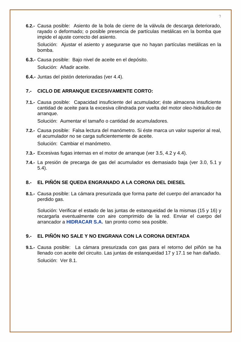
8.- EL PIÑÓN SE QUEDA ENGRANADO A LA CORONA DEL DIE SEL 8.1.- Causa posible: La cámara presurizada que forma parte del cuerpo del arrancador ha
perdido gas.
Solución: Verificar el estado de las juntas de estanqueidad de la mismas (15 y 16) y recargarla eventualmente con aire comprimido de la red. Enviar el cuerpo del arrancador a HIDRACAR S.A. tan pronto como sea posible.
9.- EL PIÑÓN NO SALE Y NO ENGRANA CON LA CORONA DEN TADA 9.1.- Causa posible: La cámara presurizada con gas para el retorno del piñón se ha
llenado con aceite del circuito. Las juntas de estanqueidad 17 y 17.1 se han dañado.
Solución: Ver 8.1.

8

9

10
OPERATION AND MAINTENANCE MANUAL
INDEX: I ) STARTING INSTRUCTIONS AND CIRCUIT LAYOUT. II ) MAINTENANCE INSTRUCTIONS. III ) TROUBLESHOOTING. I ) STARTING INTRUCTIONS AND CIRCUIT LAYOUT 1.- Check that the oil level in the tank fills the upper level indicator window.
NOTE: Every time the oleo-hydraulic starter is used a small amount of oil is used to lubricate the internal mechanisms of the starter (When the oil level falls down below the lower indicator window the tank must be then filled again up to the upper level indicator window. Use always the same kind of oil and make sure it is completely clean and filtered).
Use hydraulic oil with 4,5 °E mean viscosity and an index of 120 or more, ASTM d2270 norm.
2.- Fill up the oleo-pneumatic
accumulator (2) (see diagram) pumping oil from the tank with the hand pump (3) making sure that the command,/,starting valve (4) is closed (the handle must be perpendicular to the valve axis).
On starting to pump, the pressure gauge pointer will visibly throb up with each pumping movement, until the oil pressure reaches the accumulator’s 100 bar N2 gas pre-charge pressure.

11
At that point, the pressure gauge pointer will stop and will then start moving, initially, much more slowly, and increasingly faster as it gets closer to the 200 bar mark (the starter working pressure). The green zone in the pressure gauge indicator represents the oil filling range.
NOTE: The point (7) in the oleo-hydraulic scheme indicates an eventual external source of oil
pressure. In this case, a check valve (6) must be installed.
IMPORTANT NOTE:
Once the SAE flange has been attached to the Diesel engine body and the body of the starter has been conveniently positioned, DON’T FORGET to tighten the Allen bolts (4) that hold the SAE flange to the body of the starter.
3.- TO START: 3.1.- Open the command valve (4) turning the handle slow but continuously. The pinion
engaging the Diesel engine crown flywheel will be heard and then, immediately, the crankshaft will start turning to begin the starting cycle.
3.2.- Once the Diesel engine has been started, turn the command valve handle quickly back to its initial position. The pinion will disengage automatically from the crown flywheel by means of the N2 gas compressed in the chamber at the back of the starter body (see cross-cut components list).
If the Diesel engine has not started after using all the oil stored in the accumulator, then turn again the command valve handle to its closed and fill again the accumulator pumping oil with the hand pump.
II ) MAINTENANCE INSTRUCTIONS
1.- We recommend to perform the starting operation periodically to check the working
order of the starter (every two months approximately). 2.- Check the oil level in the tank is correct. 3.- Watch in every starting operation, when pumping oil to fill the accumulator, that the
pressure gauge pointer moves very quickly until the pressure raise to 100 bar and then stops and from then on the pressure increases very slowly with each pumping movement. If the point where the pointer change of speed is lower than 100 bar (note that it must never be higher than this value) it means that the accumulator has lost gas.
III ) TROUBLESHOOTING
ATENTION: In order to prevent any personal injury, prior to disassembling any part of the oleo-hydraulic starter, ALL THE REMAINING OIL EXISTING IN THE ACCUMULATOR MUST BE DISCHARGED TO THE TANK. Once this operation has been done do not forget that there still are gas (NITROGEN) inside the accumulator at 100 bar.

12
1.- EITHER THE HAND PUMP OR THE MOTOR-DRIVEN PUMP DOESN’T BUILD
ANY PRESSURE: 1.1.- Possible cause: Presence of air or any other substance, dirt or object obstructing the
pipes or ports between the pumps and the accumulator.
Solution: Purge the remaining air. Clean with compressed air.
1.2.- Check the pump’s drive belt tension (if there’s one). 1.3.- Possible cause: The discharge valve, if there is a motor-driven pump installed, leaks
oil which re-circulates back to the tank.
Solution: Check that the valve spring is not broken or loose, or that its compression nut is not properly set. Check the presence of dirt in the valve seat (in circuits with only hand pump, this valve is not installed) and clean it.
1.4.- Possible cause: The pump’s inlet port is obstructed.
Solution: Clean the dirt.
1.5.- Possible cause: Check that valves don’t leak.
Solution: Change them.
2.- INSUFFICIENT PRESSURE IN THE SYSTEM: 2.1.- Possible cause: Discharge valve with its compression nut improperly set.
Solution: Adjust the compression nut to provide the spring the required pressure (in circuits with only manual pump this valve is not installed).
2.2.- Possible cause: Oil level in the tank too low.
Solution: Fill the oil tank to the proper level.
2.3.- Possible cause: Damaged or inaccurate pressure gauge.
Solution: Change it.
2.4.- Check that the starting valve handle is its correct charge position.
3.- THE BENDIX PINION TURNS SLOWLY OR DOESN’T TURN AT A LL: 3.0.- The accumulator lacks enough gas pressure for working properly.
The initial gas (dry Nitrogen) pressure is 100 bar. When oil is pumped with the hand pump the actual gas charge pressure can be detected just by observing the pressure gauge pointer: it throbs up visibly with each pumping movement. When the oil pressure equals the accumulator’s inner gas pressure the pressure gauge pointer stops for a while even though the the pump handle keeps being moved and then it starts to move up again at a lower speed.
If the accumulator has lost part of its initial gas charge, below 70 bar, dismantle the accumulator FOLLOWING VERY PRECISELY THE DISMANTLING INSTRUCTIONS (available from HIDRACAR S.A. Fax: 34 9383301950).

13
Proceed to change the piston gasket and charge with DRY NITROGEN with the original charging kit (available from HIDRACAR S.A.) Or if you want, you can send it to HIDRACAR S.A. for revision and gas charge at 100 bar.
3.1.- Possible cause: Excessive viscosity of the oil.
Solution: Use oils for oleo-hydraulic circuits of 4.5 °E at 50 °C with a viscosity index >120 (oil must be compatible with Nitrile rubber).
3.2.- Possible cause: Excessive viscosity of the Diesel engine oil.
Solution: Change it for oil with the adequate viscosity. Check the manufacturer’s engine specifications for reference.
3.3.- Possible cause: Command valve partially open.
Solution: Open completely.
3.4.- Possible cause: The practical internal section of the pipe between the accumulator and the Bendix pinion oleo-hydraulic starter motor is too small.
Solution: Change the pipe for another with the adequate diameter (always use pipes with a nominal diameter equal or superior to the size of the main control valve and return tank connections) and make sure it is not partially obstructed.
3.5.- Possible cause: Excessive internal leakage in the oleo-hydraulic starter motor.
Solution: Take the starter apart and send it to HIDRACAR S.A. for its revision as soon as possible.
3.6.- Possible cause: Excessive piping length between accumulator and hydraulic motor and,/,or from hydraulic motor to tank; or pipe internal diameter too small.
Solution: Change the piping for another – shorter - run with the adequate diameter (always use the same pipe size as the main control valve and return tank connections).
4.- IMPORTANT LOSS OF OIL FROM THE TANK: 4.1.- Possible cause: External pressure circuit leakage.
Solution: Check any leakage in pipes, adapters, etc. And replace any defective piece.
4.2.- Possible cause: Leakage inside the starter body (TAKE NOTE THAT IN EACH STARTING OPERATION A VERY SMALL QUANTITY OF OIL IS USED INSIDE THE STARTER BODY TO LUBRICATE THE INTERNAL TURNING COMPONENTS).
Solution: Remove the Bendix pinion cap joint flange and look for any leaks. If confirmed, send the starter to HIDRACAR S.A. for revision as soon as possible.
4.3.- Possible cause: Leakage in the hand pump axis.
Solution: Dismantle the hand pump and change the o-rings of the pistons.
4.4.- Possible cause: Leakage detected in the Bendix pinion area. The seals 18 & 18.1 of the pushing piston are worn out.
Solution: Change the seals.

14
5.- PRESSURE DROP INSIDE THE ACCUMULATOR: 5.1.- Ambient temperature drop. It is normal a certain pressure drop when the ambient
temperature descends. For every 3 °C (Celsius) temp erature drop, the gas pressure inside the accumulator will also drop approx. in 1 bar.
5.2.- Possible cause: Leakage across the command valve.
Solution: Disconnect the adapter after the valve to see if there is any oil leakage present. Change the valve as soon as you can.
5.3.- Possible cause: Leakage through the hand pump check valve.
Solution: Disassemble the pump and clean the valve seat with compressed air.
5.4.- Possible cause: N2 gas leakage from the accumulator. The initial pre-charge gas pressure is 100 bar. Following what is said in section 2 of chapter I, (page 8) confirms a gas pressure drop in the accumulator below 70 bar.
Solution: Dismantle the accumulator FOLLOWING VERY PRECISELY THE DISMANTLING INSTRUCTIONS (available from HIDRACAR S.A. Fax: 34 9383301950), change the piston seals and recharge with DRY NITROGEN with the original charging,/ filling kit (available from HIDRACAR S.A.
6.- THE HAND PUMP CAN’T DELIVER THE MAXIMUM ACCUM ULATOR PRESSURE
(Usually 200 bar): 6.1.- The discharge valve is not closed enough.
6.2.- Possible cause: The valve does not seat well. The valve seat could be deteriorated, scratched or deformed; or there could be metal particles in the pump preventing proper seating.
Solution: Adjust the seating and make sure there are no metal particles present in the pump.
6.3.- Possible cause: The oil level in the tank is too low.
Solution: Add oil.
6.4.- Piston seals worn out (see 4.4).
7.- STARTING CYCLE TOO SHORT: 7.1.- Possible cause: Accumulator too small. The oil stored is insufficient to provide the
necessary rotations of the engine crankshaft.
Solution: Increase the size and,/,or the number of accumulators (see in our catalogue the formula to calculate the number of crankshaft revolutions depending on the accumulator’s size).
7.2.- Possible cause: The pressure gauge gives a false reading. If it gives a higher reading than the actual one the amount of oil charged is insufficient.
Solution: Check it and change it if necessary.
7.3.- Excessive internal oil leakage into the oleo-hydraulic starter motor (see 3.5, 4.2 & 4.4).

15
7.4.- The accumulator’s pre-charge gas pressure is too low (see 3.0, 5.1 & 5.4).
8.- THE PINION REMAINS ENGAGED TO THE ENGINE CROWN FLYWHEEL: 8.1.- Possible cause: The starter pressurised gas chamber has a lost gas. The seals 15 &
16 are probably damaged.
Solution: Check the condition of seals 15 & 16. Recharge the chamber through a temporary connection between the valve 3 and an available compressed air line. Send the starter as soon as possible to HIDRACAR S.A. for repair.
9.- THE PINION DOESN’T MOVE OUT AND THEREFORE DOESN’T ENGAGE THE
ENGINE CROWN FLYWHEEL EITHER: 9.1.- Possible cause: Oil from the circuit has entered into the pinion return pressurised
gas chamber. Seals 17 & 17.1 are damaged.
Solution: Follow as in 8.1.
HIDRACAR S.A. • Pol. Ind. Les Vives – c/ Anaïs Nin, 14 08295 Sant Vicenç de Castellet, Barcelona (SPAIN)
www.hidracar.com • E-mail: [email protected] • Tel.: +34 93 833 02 52 Fax: +34 93 833 19 50