Cross Layer Optimization for Packet Scheduling in Wireless ...
ARQ-based Cross-layer Optimization for
Wireless Multicarrier Transmission on
Cognitive Radio Networks
Alexandre de Baynast, Petri Mahonen, Marina Petrova
RWTH Aachen University
Department of Wireless Networks
Kackertstrasse 9
Aachen 52072, Germany
Email: [email protected]
Abstract
The primary feature of cognitive radios for wireless communication systems is thecapability to optimize the relevant communication parameters given a dynamic wire-less channel environment. Recently, several research groups have presented promis-ing preliminary results on the benefit of extending the cognitive process at thesystem level, capable of perceiving current network conditions and then acting ac-cording to end-to-end goals. System optimization however implies some challengingtasks: 1) Current network state information has to be known at all transmitters. Thisdramatically increases the amount of overhead as the number of parameters becomeslarge; 2) System optimization is often a nonlinear problem with inter-parameter de-pendencies; 3) The optimization process should also support a dynamic quality ofservice (QoS) management scheme depending on the available network resources. Inthis paper, we invoke genetic algorithms (GAs) for iteratively finding the optimumparameters based on the acknowledgment (ACK) signal only. Neither network stateinformation nor channel estimation is required. The set of accurate objective func-tions that we derive in our GA implementation control the optimization process atthe system level toward any QoS. Simulation results show that our implementationachieves comparable performance to an exhaustive search over the whole set of pa-rameters for which perfect network state information at the transmitter is assumed.It also outperforms the conventional scheme for which parameters are optimized ateach layer separately.
Key words: Cross-layer optimization in cognitive radio networks, Impact ofOFDM techniques for cognitive radio networks, WLAN applications of CRtechnology, Routing and association in cognitive wireless network, GeneticAlgorithm.
Preprint submitted to Elsevier 14 November 2007
1 Introduction
The tremendous success of wireless and data communications is driving usto find new enabling technologies to increase efficiency of wireless communi-cations. The paradigm of cognitive radios was introduced by Joseph MitolaIII less than a decade ago in 1999 Mitola, III and Maguire, Jr. (1999) (seealso Mitola (2000)). Whereas most of the work so far has focused on consid-ering the cognitive radios as a new technology for spectrum sharing, and thecognitive radio term is sometimes used also with more limited scope to de-note spectrum agile radios, (see for instance Buddhikot (2007) and referencestherein), we consider, throughout the paper, Mitola’s cognitive radio in whichevery possible parameter observable by a wireless node is taken into accountto make it adaptive and context sensitive. Cognitive radio is an ideal extensionfor software-defined radio as it provides machine-learning based and efficientautomatic optimization for a fully reconfigurable wireless black box that au-tomatically changes its transmission or reception parameters in response tocurrent network state and user demands.
The cognitive radios themselves are only a narrow aspect of a larger context, ifone is considering the optimization of the overall capacity and QoS. A singleradio-centric approach is not enough in the situation where cognitive andintelligent methods are used to enhance all system aspects in the contextof wireless networks. Recently a number of authors have started to considerthe issues related to Cognitive Wireless Networks (see for example works ofPetrova et al. (2006), Nolan and Doyle (2007), Thomas et al. (2005), Thomaset al. (2006), Petrova and Mahonen (2007a), and Mahonen (2004)).
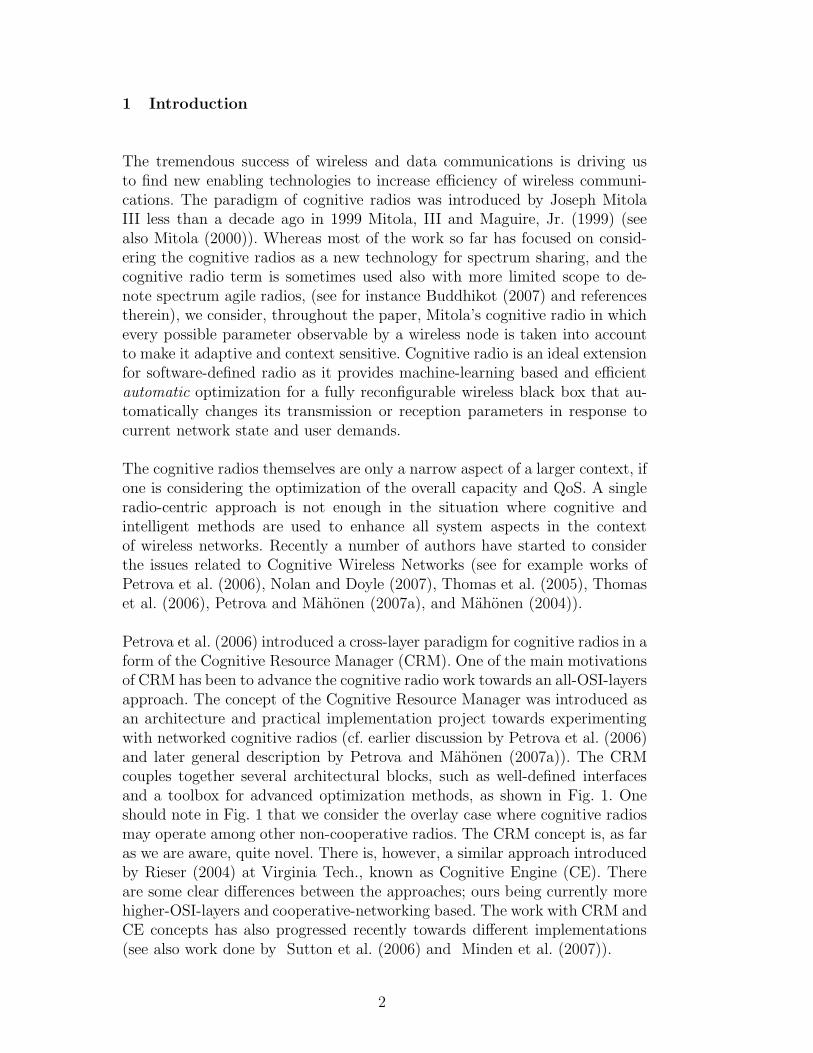
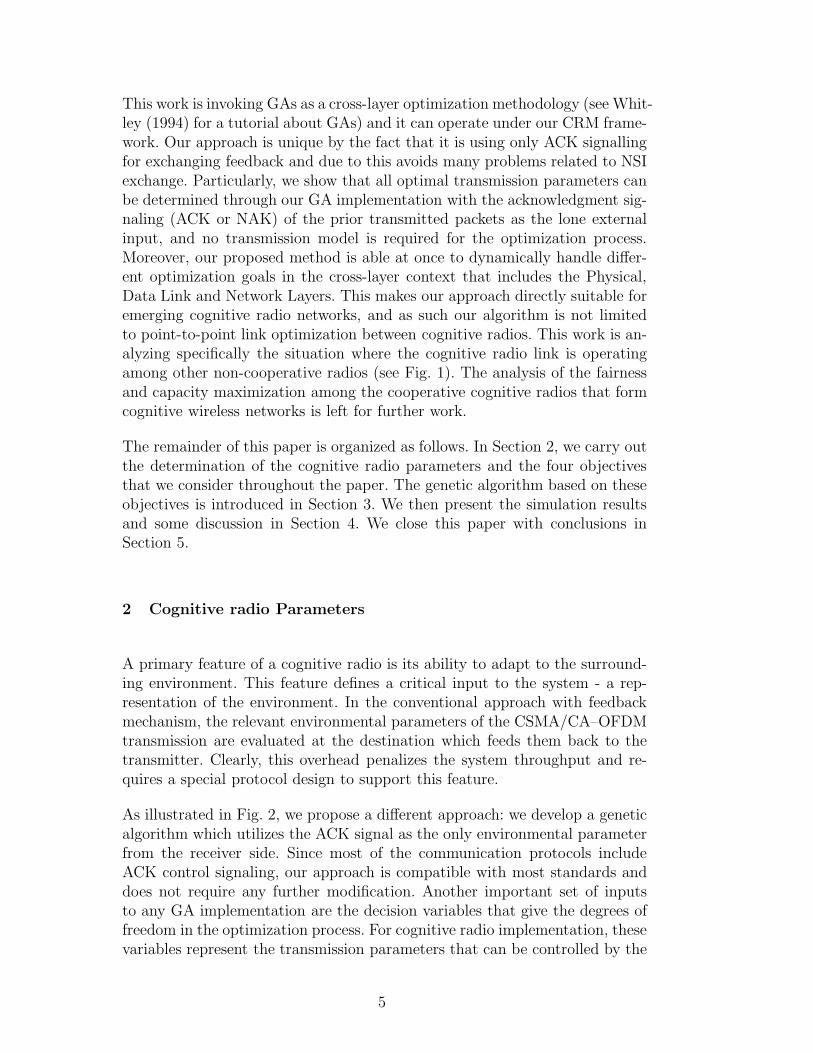
Petrova et al. (2006) introduced a cross-layer paradigm for cognitive radios in aform of the Cognitive Resource Manager (CRM). One of the main motivationsof CRM has been to advance the cognitive radio work towards an all-OSI-layersapproach. The concept of the Cognitive Resource Manager was introduced asan architecture and practical implementation project towards experimentingwith networked cognitive radios (cf. earlier discussion by Petrova et al. (2006)and later general description by Petrova and Mahonen (2007a)). The CRMcouples together several architectural blocks, such as well-defined interfacesand a toolbox for advanced optimization methods, as shown in Fig. 1. Oneshould note in Fig. 1 that we consider the overlay case where cognitive radiosmay operate among other non-cooperative radios. The CRM concept is, as faras we are aware, quite novel. There is, however, a similar approach introducedby Rieser (2004) at Virginia Tech., known as Cognitive Engine (CE). Thereare some clear differences between the approaches; ours being currently morehigher-OSI-layers and cooperative-networking based. The work with CRM andCE concepts has also progressed recently towards different implementations(see also work done by Sutton et al. (2006) and Minden et al. (2007)).
2
��������������������
��������������������
��������������������
��������������������
CR
RR
R
R
CR
R
R
CR
Internet
Internet
Fig. 1. Functional architecture of the Cognitive Radio Manager with the interfacesto different entities.
Instead of concentrating on physical layer as many previous cognitive ra-dio studies (see Newman et al. (2007) and Rieser (2004) for instance), CRMstrictly follows the approach of enabling cross-layer optimization with artificial-intelligence-based learning and adaptation. The key idea behind CRM is thatit closely coordinates the interplay between cross-layer optimization function-alities and machine-learning-based algorithms. One of the corner stones forCRM is to follow the approach proposed by Song and Li (2005) based onutility functions that tradeoff the fairness and efficiency of resource allocationbased on the QoS requirements of each user. Hence the application layer cannegotiate with CRM the QoS requirements, e.g., delay bounds, throughput,depending on the available network resources and the physical resources avail-able at the transmitter. For other relevant discussions on using a cross-layerapproach with cognitive networks the reader should note work by Baldo andZorzi (2007), and more generally by Johansson et al. (2006), and a review ondecomposition methods by Mung Chiang et al. (2007). Additional examplesare provided by Kawadia and Kumar (2005), who also discuss the possiblepitfalls of cross-layer optimization.
Whereas CRM and CE frameworks may dramatically enhance overall perfor-mance when applied to point-to-point wireless links or towards full cognitiveradio networks, there are, however, several potential drawbacks and designissues that must be overcome especially in the networked environment:
(1) Current full or partial network state information (NSI) has to be known ateach transmitter. NSI estimation requires large overhead, especially in atime-varying environment and for large wireless networks. In fact, CRMmay decrease the overall throughput due to high overhead, unless thedesign of the system takes in account the overhead of state informationexchange,
(2) Since CRM performs non-linear optimizations over large-dimension spaces,the computational complexity may become a major burden for hardwareimplementation and it is not a trivial issue to ensure that CRM canreduce the power consumption overall,
(3) Moreover, non-linear optimization methods traditionally require numer-
3
ous internal tuning parameters; For instance, genetic algorithms withmultiple objective functions require weights determination, crossover, mu-tation, elitism rates, just to mention a few main parameters. If these pa-rameters are not well set due, for example, to a poor NSI estimation, theCRM approach can lead the system to an unstable state and traditionalapproaches lead to better performance,
(4) Finally, CRM implies the need to develop a set of complex and efficientdecision making units that estimate NSI, and control the relevant com-munication parameters to optimize system performance. If the decisionunits are not well designed, CRM may take suboptimal decisions and infact deteriorate performance compared to a conventional approach.
Moreover one should note that the utility-based optimization in the networkedwireless environment is not a straightforward issue. The main problem is tofind the utility function for optimization. The simplistic approach for opti-mizing just one parameter between two wireless devices, e.g., maximizing linkthroughput or minimizing bit-error rate might have adverse effects for otherusers or might effect the overall capacity of the network in unknown ways.Even in the case of a single wireless link, there is often a combination of dif-ferent, and competing, goals to be taken in account in order to achieve suitablequality for communications (see also Newman et al. (2007)). The problem ofknowing NSI at the right level has been pointed out recently in different mod-eling contexts; Petrova and Mahonen (2007b) introduced it through Value ofPerfect Information (VPI) models, and Thomas et al. (2007) independentlyfound a complementary description as the price of ignorance.
In this paper, we present a simple strategy for a cognitive radio system whichattempts to alleviate these potential problems. Throughout the paper, we fo-cus, without loss of generality, on the wireless orthogonal frequency-divisionmultiplexing (OFDM) system with Medium Access Control (MAC) layer thatis based on the Carrier Sense Multiple Access (CSMA) with Collision Avoid-ance (CA) protocol as for example in IEEE 802.11 (1999) standard, but ourapproach can be extended to other wireless systems.
The choice of OFDM as an underlying physical layer technology is well justifiedas many current and future commercial standards are based on this technology.Furthermore, the use of OFDM enables more direct comparison of our resultswith other techniques. At the MAC layer, the CSMA/CA protocol is chosen asit is quite generic and also widely used in 802.11-based systems. However, ourapproach can be extended to other MAC protocols. Specifically, we propose anAutomatic Repeat reQuest (ARQ)-based protocol for cognitive radio systemthat controls the transmission QoS in terms of delay, throughput, packet lossrate and transmission power consumption along the lines of Ying Jun Zhangand Letaief (2006).
4
This work is invoking GAs as a cross-layer optimization methodology (see Whit-ley (1994) for a tutorial about GAs) and it can operate under our CRM frame-work. Our approach is unique by the fact that it is using only ACK signallingfor exchanging feedback and due to this avoids many problems related to NSIexchange. Particularly, we show that all optimal transmission parameters canbe determined through our GA implementation with the acknowledgment sig-naling (ACK or NAK) of the prior transmitted packets as the lone externalinput, and no transmission model is required for the optimization process.Moreover, our proposed method is able at once to dynamically handle differ-ent optimization goals in the cross-layer context that includes the Physical,Data Link and Network Layers. This makes our approach directly suitable foremerging cognitive radio networks, and as such our algorithm is not limitedto point-to-point link optimization between cognitive radios. This work is an-alyzing specifically the situation where the cognitive radio link is operatingamong other non-cooperative radios (see Fig. 1). The analysis of the fairnessand capacity maximization among the cooperative cognitive radios that formcognitive wireless networks is left for further work.
The remainder of this paper is organized as follows. In Section 2, we carry outthe determination of the cognitive radio parameters and the four objectivesthat we consider throughout the paper. The genetic algorithm based on theseobjectives is introduced in Section 3. We then present the simulation resultsand some discussion in Section 4. We close this paper with conclusions inSection 5.
2 Cognitive radio Parameters
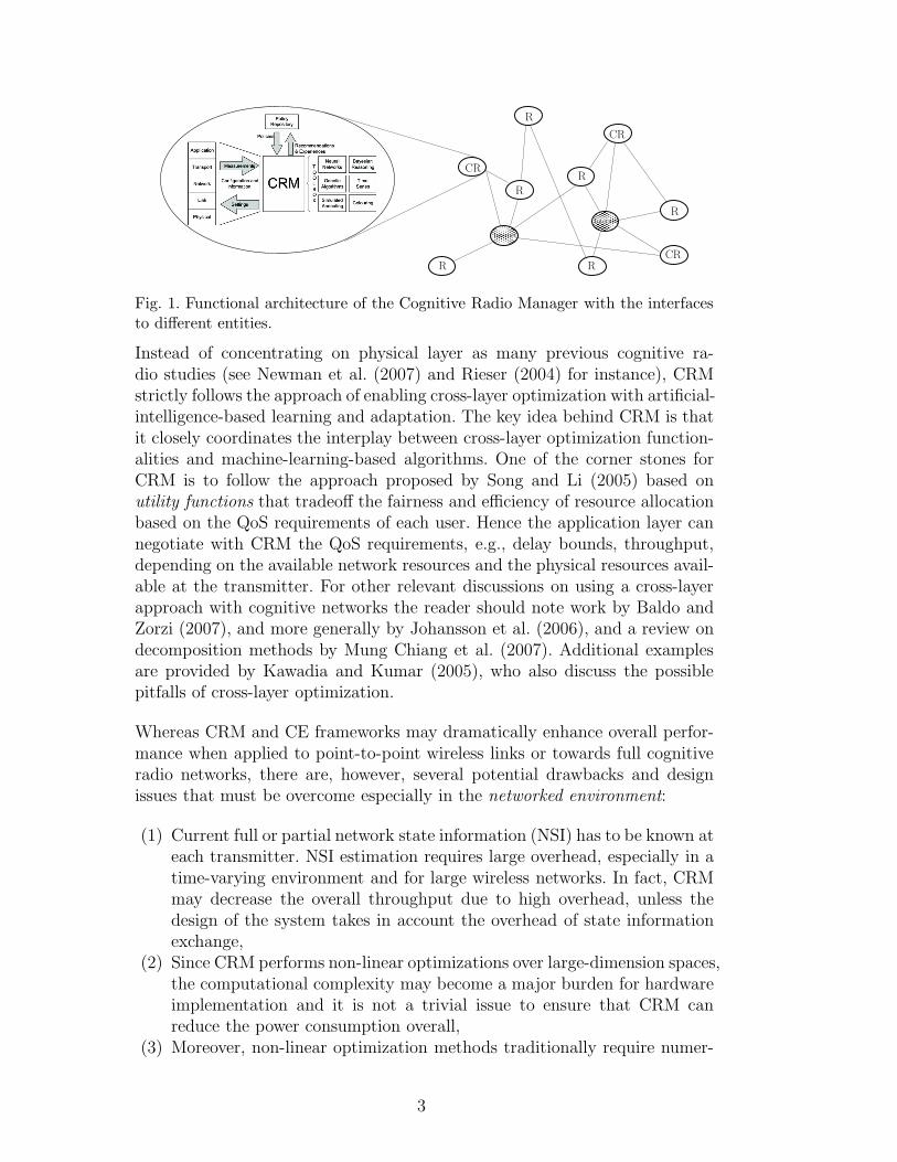
A primary feature of a cognitive radio is its ability to adapt to the surround-ing environment. This feature defines a critical input to the system - a rep-resentation of the environment. In the conventional approach with feedbackmechanism, the relevant environmental parameters of the CSMA/CA–OFDMtransmission are evaluated at the destination which feeds them back to thetransmitter. Clearly, this overhead penalizes the system throughput and re-quires a special protocol design to support this feature.
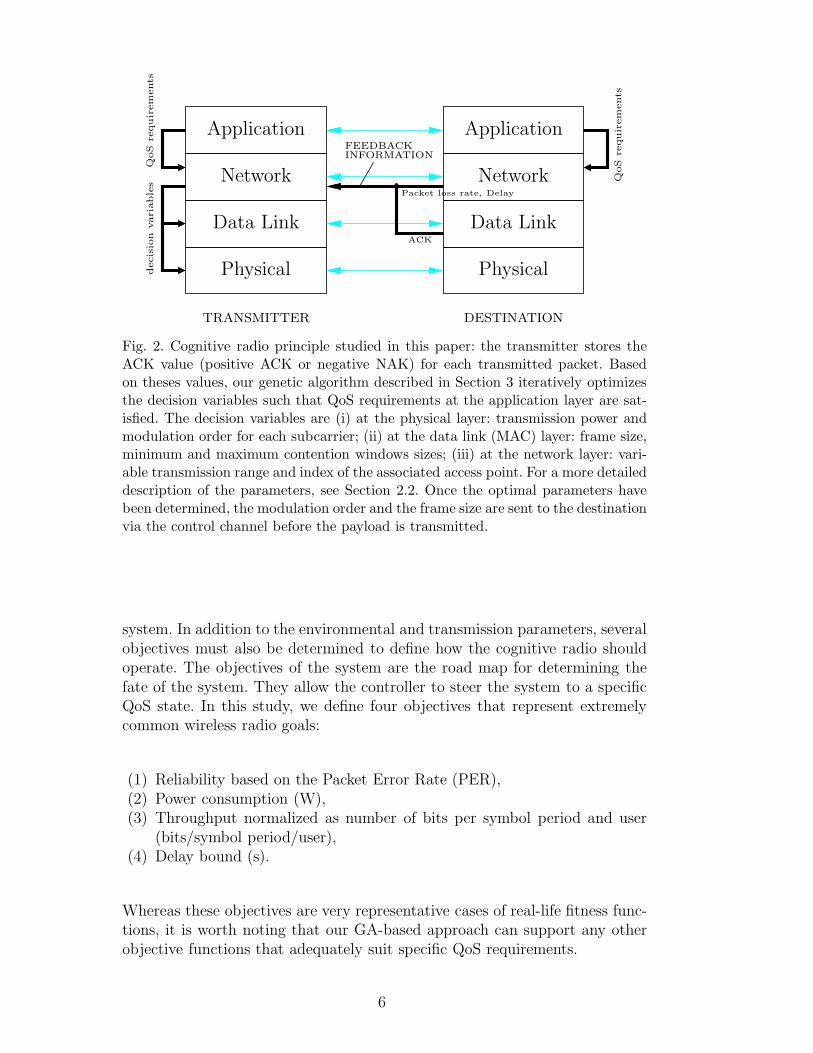
As illustrated in Fig. 2, we propose a different approach: we develop a geneticalgorithm which utilizes the ACK signal as the only environmental parameterfrom the receiver side. Since most of the communication protocols includeACK control signaling, our approach is compatible with most standards anddoes not require any further modification. Another important set of inputsto any GA implementation are the decision variables that give the degrees offreedom in the optimization process. For cognitive radio implementation, thesevariables represent the transmission parameters that can be controlled by the
5
Application
Data Link
Physical
Data Link
Physical
NetworkNetwork
Applicationdecis
ion
varia
ble
s
QoS
requir
em
ents
QoS
requir
em
ents
FEEDBACKINFORMATION
Packet loss rate, Delay
ACK
TRANSMITTER DESTINATION
Fig. 2. Cognitive radio principle studied in this paper: the transmitter stores theACK value (positive ACK or negative NAK) for each transmitted packet. Basedon theses values, our genetic algorithm described in Section 3 iteratively optimizesthe decision variables such that QoS requirements at the application layer are sat-isfied. The decision variables are (i) at the physical layer: transmission power andmodulation order for each subcarrier; (ii) at the data link (MAC) layer: frame size,minimum and maximum contention windows sizes; (iii) at the network layer: vari-able transmission range and index of the associated access point. For a more detaileddescription of the parameters, see Section 2.2. Once the optimal parameters havebeen determined, the modulation order and the frame size are sent to the destinationvia the control channel before the payload is transmitted.
system. In addition to the environmental and transmission parameters, severalobjectives must also be determined to define how the cognitive radio shouldoperate. The objectives of the system are the road map for determining thefate of the system. They allow the controller to steer the system to a specificQoS state. In this study, we define four objectives that represent extremelycommon wireless radio goals:
(1) Reliability based on the Packet Error Rate (PER),(2) Power consumption (W),(3) Throughput normalized as number of bits per symbol period and user
(bits/symbol period/user),(4) Delay bound (s).
Whereas these objectives are very representative cases of real-life fitness func-tions, it is worth noting that our GA-based approach can support any otherobjective functions that adequately suit specific QoS requirements.
6
2.1 Environment Parameters
Environmental variables inform the system of the characteristics of the sur-rounding environment. This information is used to aide the cognitive controllerin making decisions. These variables are primarily used as inputs to GA, soit is essential to accurately estimate them. As aforementioned, we restrict theset of environmental parameters that are determined at the destination, toACK signaling. If there is no ACK signal in the protocol, our approach canalso use an estimate of the transmission packet error probability which canbe provided, for instance, at the output of the error-correcting decoder at thephysical layer. In our protocol, we assume the knowledge of the following setof parameters at the transmitter:
(1) ACK signal (positive ACK or negative NAK),(2) Number of occurrences that a packet transmission has been successful.
Denote τ as the ratio between this number divided by the total transmis-sion time in term of time slot; the parameter τ can be evaluated with abasic counter which is incremented each time a positive ACK is received.In order to accurately evaluate τ for the current network state, we assumethat the counter is periodically reset to zero,
(3) Number of occurrences that a packet transmission has been unsuccessful.Denote τ ′ as the ratio between this number divided by the total trans-mission time in term of time slot. Note that τ ′ can be determined directlyfrom τ .
If additional information about the current network status, e.g., the propaga-tion channel impulse response(s) or the current number of active users in thenetwork is available at the transmitter, the GA can employ this informationto ameliorate the optimization process of the transmission parameters.
2.2 Decision Variables
Cognitive radios become possible when the radio components permit the mod-ification of the transmission parameters. These decision variables are set bythe cognitive component once an optimal decision has been formulated usingthe GA. Defining a complete list of decision variables to generate a generic fit-ness function usable by all radios is difficult. A goal of this paper is to define aset of decision variables at the physical, link and network layers, large enoughto guarantee that it is a representative sample for most cognitive radios. Thetransmission parameters used as outputs in our GA implementation are shownin Table 1.
7
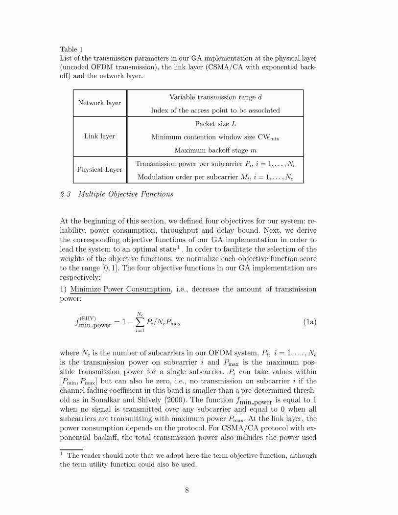
Table 1List of the transmission parameters in our GA implementation at the physical layer(uncoded OFDM transmission), the link layer (CSMA/CA with exponential back-off) and the network layer.
Network layerVariable transmission range d
Index of the access point to be associated
Link layer
Packet size L
Minimum contention window size CWmin
Maximum backoff stage m
Physical LayerTransmission power per subcarrier Pi, i = 1, . . . ,Nc
Modulation order per subcarrier Mi, i = 1, . . . ,Nc
2.3 Multiple Objective Functions
At the beginning of this section, we defined four objectives for our system: re-liability, power consumption, throughput and delay bound. Next, we derivethe corresponding objective functions of our GA implementation in order tolead the system to an optimal state 1 . In order to facilitate the selection of theweights of the objective functions, we normalize each objective function scoreto the range [0, 1]. The four objective functions in our GA implementation arerespectively:
1) Minimize Power Consumption, i.e., decrease the amount of transmissionpower:
f(PHY)
min power = 1 −Nc∑
i=1
Pi/NcPmax (1a)
where Nc is the number of subcarriers in our OFDM system, Pi, i = 1, . . . , Nc
is the transmission power on subcarrier i and Pmax is the maximum pos-sible transmission power for a single subcarrier. Pi can take values within[Pmin, Pmax] but can also be zero, i.e., no transmission on subcarrier i if thechannel fading coefficient in this band is smaller than a pre-determined thresh-old as in Sonalkar and Shively (2000). The function fmin power is equal to 1when no signal is transmitted over any subcarrier and equal to 0 when allsubcarriers are transmitting with maximum power Pmax. At the link layer, thepower consumption depends on the protocol. For CSMA/CA protocol with ex-ponential backoff, the total transmission power also includes the power used
1 The reader should note that we adopt here the term objective function, althoughthe term utility function could also be used.
8

in packet retransmission. This yields:
f(MAC)
min power = 1 − (1 + τ ′/τ) ·Nc∑
i=1
Pi/NcPmax (1b)
with τ and τ ′ defined in Section 2.1. Strictly speaking, f(MAC)
min power can be
negative for large transmission power and high retransmission rate. However,f
(MAC)
min power is monotonically decreasing function with respect to τ and we ob-
serve in our simulations, Section 4, that using (1b) in our GA implementationdoes not deteriorate the performance. Whereas (1a) or (1b) penalizes systemstates with higher power consumption, it might be not enough to guaran-tee that the current power consumption is equal to or lower than a certainthreshold P ∗. In order to ensure this, we modify (1b) as follows:
f(MAC)
min power =
0, if∑
i Pi > P ∗,
1, if∑
i Pi ≤ P ∗;(1c)
2) Maximize Throughput, i.e., increase the overall data throughput transmit-ted by the radio. At the physical layer, the throughout per user T can beexpressed in number of bits per symbol period as T =
∑
Nc
i=1 log2(Mi)/Nc,where Mi, i = 1, . . . , Nc is the number of bits per symbol emitted on sub-carrier i, Mmax is the maximum modulation order with typical values 64 or256 in wireless networks. Mi can take values from 1 to Mmax with 1 spe-cial case occurring when subcarrier i is shut down. Mi = 1 means that therate log2(Mi) is equal to zero; no information is transmitted. In this par-ticular case, the corresponding transmission power Pi is set to zero. Clearly,we have: 0 ≤ T ≤ log2(Mmax), where the value log2(Mmax) is achieved whenall subcarriers are loaded with symbols modulated with the largest availablemodulation order. Therefore, the objective function for the throughput is sim-ply:
f(PHY)
max throughput =1
Nc log2(Mmax)·
Nc∑
i=1
log2(Mi). (2a)
The function f(PHY)
max throughput is equal to 1 when all subcarriers transmit with
largest modulation order and equal to 0 when all subcarriers are switched off.
At the link layer, the saturation throughput T can be expressed as in Bianchi(1998)
T =τ · P
∑
Nc
i=1 log2(Mi)/Nc
(1 − τ − τ ′)σ + τTs + τ ′Tc
,
9
where P is a packet duration and σ denotes a slot duration. We adopt for Ts
and Tc the same definitions as Bianchi (1998), i.e., Ts is the duration betweenthe end of a packet transmission and the reception of the corresponding ACKsignal, and Tc is the maximum delay after each packet transmission beforedeclaring that the packet is lost.
An upper bound on the throughput T occurs if the highest modulation orderMmax is used for all subcarriers and if all packet transmissions are successfulwhich yields Tmax = (P · log2 Mmax)/Ts. Therefore, the objective function forthe CSMA/CA throughput can be expressed as the ratio between T and Tmax
f(MAC)
max throughput =τ · Ts ·
∑
Nc
i=1 log2(Mi)
[(1 − τ − τ ′)σ + τTs + τ ′Tc] Nc log2(Mmax). (2b)
Whereas (2a) or (2b) penalizes system with lower throughput, it might be notenough to guarantee that the current throughput exceeds a certain thresholdT ∗. As for the transmission power, we therefore modify (2b) as follows:
f(MAC)
max throughput =
0 if T < T ∗,
1 if T ≥ T ∗;(2c)
3) Minimize Bit/Packet-Error-Rate, i.e., improve the reliability of the trans-mission. One possible objective function for characterizing the reliability ofthe system is:
fmin ber = 1 − log(0.5)/ log(P e), (3a)
where P e is the average bit-wise probability of error per subcarrier. This ob-jective function which was initially proposed by Newman et al. (2007), has twodrawbacks in our context. First, the receiver estimates the probability of errorof the transmission and forwards a quantized version of it to the transmit-ter. This additional overhead should be included in the protocol and requiresmodification of the IEEE 802.11 standard. Second, it does not fit well withthe usual QoS requirement. QoS usually requires a maximum tolerated bitor packet error probability. Above this threshold, the communication is dis-rupted. In this paper, we propose two new objective functions for the reliabilityof the transmission: the first function ensures that packet error probability isequal to or lower than a target PER denoted as PER∗, i.e.,
fmin ber = log(max(PER∗, PER))/ log(PER∗). (3b)
This objective function penalizes only the sets of decision variables that yieldPER > PER∗; otherwise, fmin ber = 1 as long as PER ≤ PER∗. In other
10

words, any set which satisfies PER ≤ PER∗ would be optimal from the PERminimization viewpoint independently if PER = PER∗ or PER =PER∗/1000.The second objective function that we propose here is a binary version of (3b),i.e.,
fmin ber =
0 if PER > PER∗,
1 if PER ≤ PER∗.(3c)
As (3b), (3c) also ensures that packet error probability is equal to or lowerthan PER∗. In addition, it requires at the transmitter the knowledge thatthe packet has been successfully transmitted or has been lost (collision withother users or transmission error due to the transmission channel distortion).Therefore, (3c) can be estimated from the acknowledgment signaling valueonly.
4) Minimize Transmission Delay, i.e., decreasing the time interval between twosuccessful packet transmissions. The objective function for characterizing thedelay bound of the system is
f(PHY)
min delay =L · log2(Mmax)
Lmin∑
Nc
i=1 log2(Mi), (4a)
where L and Lmin are the current and minimum packet lengths, respectively.At the link layer, packet retransmissions have to be taken into account. Theobjective function becomes
f(MAC)
min delay =L · log2(Mmax)⌈1/τ⌉
Lmin∑
Nc
i=1 log2(Mi). (4b)
2.4 A Weighted Approach
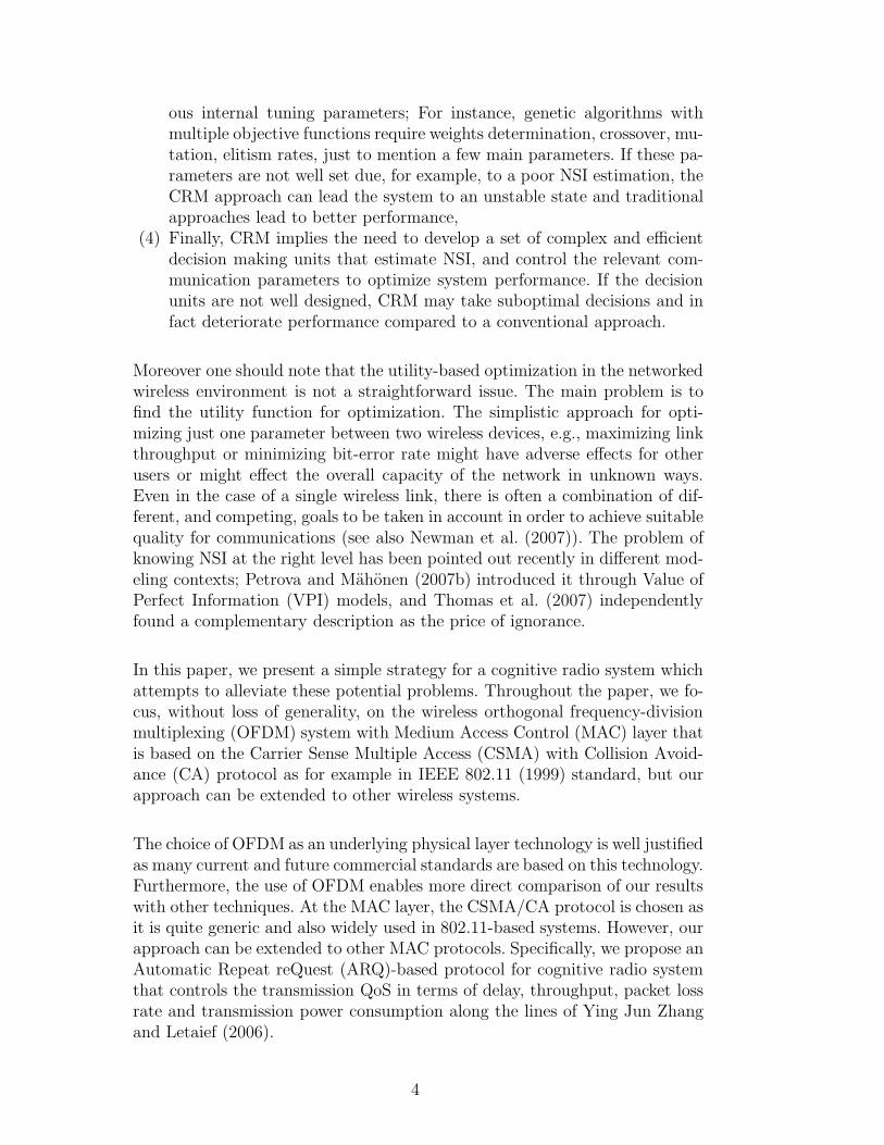
Using the four objectives (1), (2), (3) and (4) as sole inputs to the GA fit-ness function will not suffice. In a wireless communication environment, thereare several desirable objectives that the radio system may want to achieve.It is ambiguous to have, for example, the system maximizing the through-put while also minimizing PER. At the physical layer, this creates a conflictdue to the single parameter, the modulation order Mi as is illustrated inFig. 3. The optimal set for both objective functions lies on what is knownas the Pareto optimal front, Fonseca and Fleming (1998a). This front repre-sents the set of solutions that cannot be improved upon in any dimension.The solutions on the Pareto front are optimal and coexist due to the tradeoffsbetween the multiple objectives. In this example, the Pareto optimal front
11
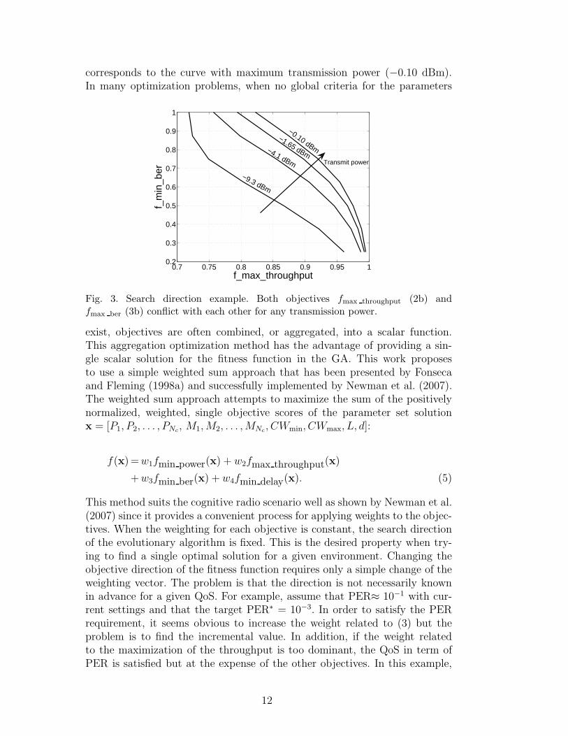
corresponds to the curve with maximum transmission power (−0.10 dBm).In many optimization problems, when no global criteria for the parameters
0.7 0.75 0.8 0.85 0.9 0.95 10.2
0.3
0.4
0.5
0.6
0.7
0.8
0.9
1
f_max_throughput
f_m
in_b
er
−9.3 dBm
−4.1 dBm
−1.65 dBm
−0.10 dBm
Transmit power
Fig. 3. Search direction example. Both objectives fmax throughput (2b) andfmax ber (3b) conflict with each other for any transmission power.
exist, objectives are often combined, or aggregated, into a scalar function.This aggregation optimization method has the advantage of providing a sin-gle scalar solution for the fitness function in the GA. This work proposesto use a simple weighted sum approach that has been presented by Fonsecaand Fleming (1998a) and successfully implemented by Newman et al. (2007).The weighted sum approach attempts to maximize the sum of the positivelynormalized, weighted, single objective scores of the parameter set solutionx = [P1, P2, . . . , PNc
, M1, M2, . . . , MNc, CWmin, CWmax, L, d]:
f(x)= w1fmin power(x) + w2fmax throughput(x)
+ w3fmin ber(x) + w4fmin delay(x). (5)
This method suits the cognitive radio scenario well as shown by Newman et al.(2007) since it provides a convenient process for applying weights to the objec-tives. When the weighting for each objective is constant, the search directionof the evolutionary algorithm is fixed. This is the desired property when try-ing to find a single optimal solution for a given environment. Changing theobjective direction of the fitness function requires only a simple change of theweighting vector. The problem is that the direction is not necessarily knownin advance for a given QoS. For example, assume that PER≈ 10−1 with cur-rent settings and that the target PER∗ = 10−3. In order to satisfy the PERrequirement, it seems obvious to increase the weight related to (3) but theproblem is to find the incremental value. In addition, if the weight relatedto the maximization of the throughput is too dominant, the QoS in term ofPER is satisfied but at the expense of the other objectives. In this example,
12
Table 2Example weighting scenarios — w1, w2, w3 and w4 are the weights for the objectivefunctions fmin power, fmin ber, fmax throughput and fmin delay, respectively.
QoS requirements w1 w2 w3 w4
High throughput with target PER∗ 0.1 0.1 0.8 —
Real-time with target PER∗ and throughput T∗ 0.1 0.1 0.1 0.7
the throughput will be too low or the power consumption too high. A basicstrategy would consist in updating the weights iteratively until a solution closeto the requirements is reached. However, the convergence to the optimal setof weights may be (very) slow and the approach inefficient. The strategy thatwe adopt in our GA implementation exploits the discrepancy of the solutionsin (1c), (2c) and (3c). Indeed, those objective functions may take only binaryvalues, 0 or 1, so whatever the weights are, the overall fitness function score(5) is very likely low if one or several objective function scores are equal to0. In Section 4, we validate this approach by means of simulations. Table 2summarizes these example weight vectors for several QoS requirements.
3 Proposed Genetic Algorithm
The optimization problem (5) involves non-linear functions. Additionally, thisimplies that it is not possible to treat each parameter as an independentvariable which can be solved in isolation from the other variables. There areinteractions such that the combined effects of the parameters must be con-sidered in order to maximize or minimize the solution set. As mentioned byWhitley (1994), a genetic algorithm is suitable to solve that kind of optimiza-tion problem. GAs are a family of computational models inspired by evolution.An implementation of GA begins with a population of random chromosomes.One then evaluates these structures and allocates reproductive opportunitiesin such a way that those chromosomes which represent a better solution to theobjective function are given better chances to reproduce than those chromo-somes which are poorer solutions. We assume that the variables representingthe set of parameters {P1, P2 , . . ., PNc
, M1, M2, . . ., MNc, CWmin, CWmax, L,
d} can be typified by bit strings. This means that the variables are quantizedin an a priori fashion and that the range of the quantization corresponds tosome power of 2.
The first step in our GA implementation is to generate a single initial randombit string representing a possible solution x = [P1, P2, . . ., PNc
, M1, M2, . . .,MNc
, CWmin, CWmax, L, d] to the optimization problem (5). A first payload
13
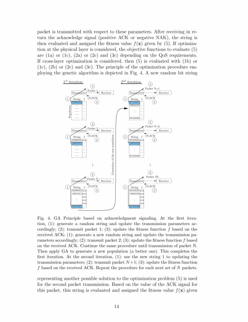
packet is transmitted with respect to these parameters. After receiving in re-turn the acknowledge signal (positive ACK or negative NAK), the string isthen evaluated and assigned the fitness value f(x) given by (5). If optimiza-tion at the physical layer is considered, the objective functions to evaluate (5)are (1a) or (1c), (2a) or (2c) and (3c) depending on the QoS requirements.If cross-layer optimization is considered, then (5) is evaluated with (1b) or(1c), (2b) or (2c) and (3c). The principle of the optimization procedure em-ploying the genetic algorithm is depicted in Fig. 4. A new random bit string
1
2
3
1
2
3
1
2
3
13
13
13
2
2
2
ReceiverTransmitterPacket 1
(N)ACKString f
Pop
ula
tion
...
ReceiverTransmitter
(N)ACKString fACK
Packet N
ReceiverTransmitter
(N)ACKString f
Packet 2
ACK
ACK
ACK
ACK
ACK
...
1st iteration:
ReceiverTransmitter
(N)ACKString f
...
ReceiverTransmitter
(N)ACKString fACK
ReceiverTransmitter
(N)ACKString fACK
ACK
ACK
ACK
ACK
...
2nd iteration:
...
...
Packet N+1
Packet N+2
Packet 2N
Gen
erat
ion
ofth
enew
pop
ula
tion
0100101
0100101
01001011001011
1001011
0101001
01101011001010
0110100
10010100110101
01101011001010
0110100
0110100
Fig. 4. GA Principle based on acknowledgment signaling. At the first itera-tion, (1): generate a random string and update the transmission parameters ac-cordingly; (2): transmit packet 1; (3): update the fitness function f based on thereceived ACK; (1): generate a new random string and update the transmission pa-rameters accordingly; (2): transmit packet 2; (3): update the fitness function f basedon the received ACK. Continue the same procedure until transmission of packet N.Then apply GA to generate a new population (a better one). This completes thefirst iteration. At the second iteration, (1): use the new string 1 to updating thetransmission parameters; (2): transmit packet N +1; (3): update the fitness functionf based on the received ACK. Repeat the procedure for each next set of N packets.
representing another possible solution to the optimization problem (5) is usedfor the second packet transmission. Based on the value of the ACK signal forthis packet, this string is evaluated and assigned the fitness value f(x) given
14
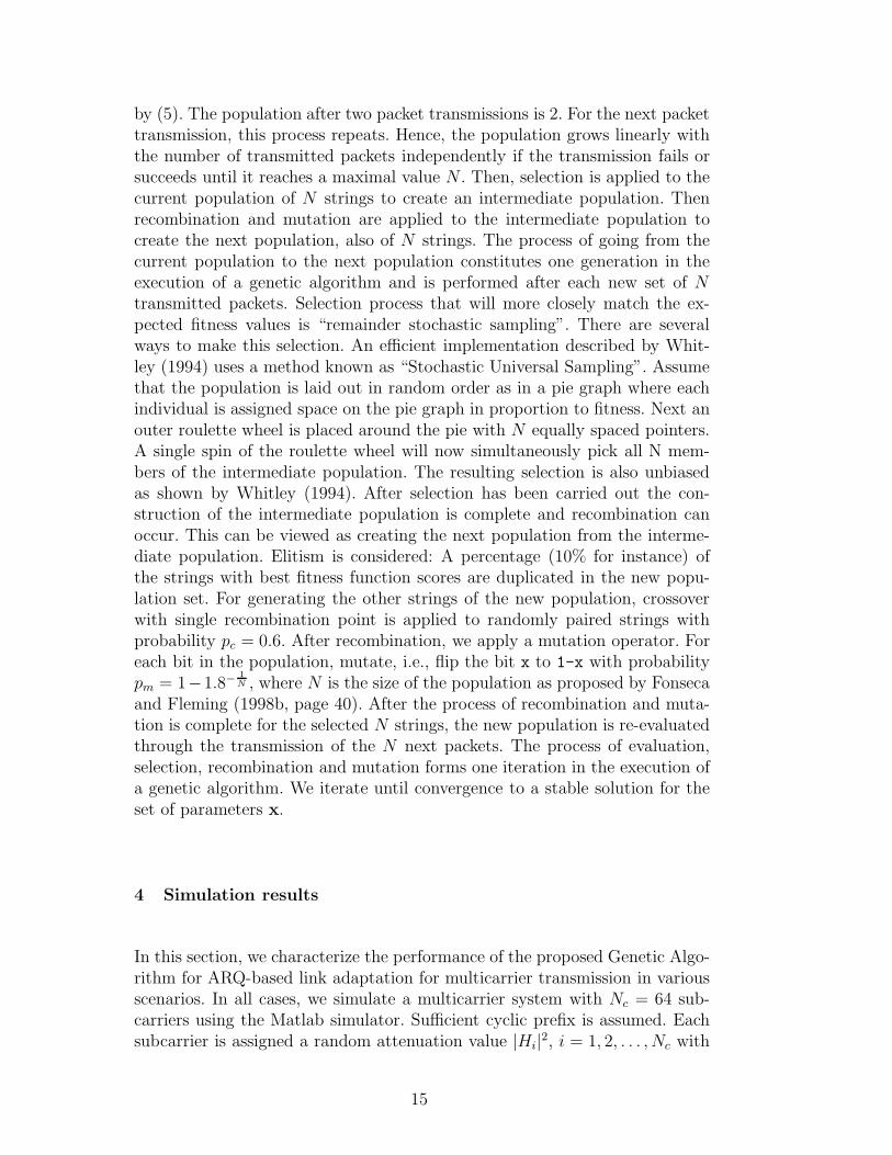
by (5). The population after two packet transmissions is 2. For the next packettransmission, this process repeats. Hence, the population grows linearly withthe number of transmitted packets independently if the transmission fails orsucceeds until it reaches a maximal value N . Then, selection is applied to thecurrent population of N strings to create an intermediate population. Thenrecombination and mutation are applied to the intermediate population tocreate the next population, also of N strings. The process of going from thecurrent population to the next population constitutes one generation in theexecution of a genetic algorithm and is performed after each new set of Ntransmitted packets. Selection process that will more closely match the ex-pected fitness values is “remainder stochastic sampling”. There are severalways to make this selection. An efficient implementation described by Whit-ley (1994) uses a method known as “Stochastic Universal Sampling”. Assumethat the population is laid out in random order as in a pie graph where eachindividual is assigned space on the pie graph in proportion to fitness. Next anouter roulette wheel is placed around the pie with N equally spaced pointers.A single spin of the roulette wheel will now simultaneously pick all N mem-bers of the intermediate population. The resulting selection is also unbiasedas shown by Whitley (1994). After selection has been carried out the con-struction of the intermediate population is complete and recombination canoccur. This can be viewed as creating the next population from the interme-diate population. Elitism is considered: A percentage (10% for instance) ofthe strings with best fitness function scores are duplicated in the new popu-lation set. For generating the other strings of the new population, crossoverwith single recombination point is applied to randomly paired strings withprobability pc = 0.6. After recombination, we apply a mutation operator. Foreach bit in the population, mutate, i.e., flip the bit x to 1-x with probabilitypm = 1−1.8−
1N , where N is the size of the population as proposed by Fonseca
and Fleming (1998b, page 40). After the process of recombination and muta-tion is complete for the selected N strings, the new population is re-evaluatedthrough the transmission of the N next packets. The process of evaluation,selection, recombination and mutation forms one iteration in the execution ofa genetic algorithm. We iterate until convergence to a stable solution for theset of parameters x.
4 Simulation results
In this section, we characterize the performance of the proposed Genetic Algo-rithm for ARQ-based link adaptation for multicarrier transmission in variousscenarios. In all cases, we simulate a multicarrier system with Nc = 64 sub-carriers using the Matlab simulator. Sufficient cyclic prefix is assumed. Eachsubcarrier is assigned a random attenuation value |Hi|
2, i = 1, 2, . . . , Nc with
15
chi-square distribution. Hence, the signal-to-noise ratio (SNR) varies indepen-dently from one subcarrier to another and induces a need for the power andrate adaptation for each individual subcarrier. The channel was assumed tobe “block-invariant”, implying that the transmission channel impulse responseremains constant or undergoes only minor changes over several consecutivepacket transmissions. We assume regular Quadrature Amplitude Modulation(QAM) signaling (4-QAM, 16-QAM and 64-QAM) but our approach can read-ily be extended to arbitrary modulations. We also permit switching off somesubcarriers if the fading is too deep for the corresponding bands. The transmis-sion power Pi can take 16 values ranging uniformly from 0.1 mW to 2.56 mW.These are example values of course and do not represent any limitation for ourGA based approach. At the link layer, adaptive contention window size is con-sidered as suggested by Bianchi (1998). We assume no RTS/CTS mechanism.The minimum contention window size CWmin can take four possible valuesbetween 4 and 32. The maximal contention window size CWmax can take 8values between 32 and 4096. The packet also has adaptive size L from 18 bytesto 2304 bytes. Finally, at the network layer, we assume multihop transmissionwith adaptive transmission range ∈ {d, d/2, d/4, d/8}. The network topology,i.e., the positions of the nodes that are assumed to be uniformly randomly dis-tributed over a given area, is taken into account by the Rayleigh distributedchannel coefficients. For high quality transmission channel, direct transmissionover distance d is performed. For poor channels, however, transmission has tobe done hop by hop separated from each other by distance d/2, d/4 or d/8depending on the transmission noise level. For practical reasons, we assumehalf-duplex transmission, i.e., any node cannot transmit and receive simulta-neously. We also assume for the considered network topology the presence ofseveral access points within the transmission range. Our GA approach selectsthe access point which provides the best QoS. Overall, with 16 possible valuesfor the transmission power, 4 possible modulation indexes, this gives 16 × 4possible values for each subcarrier. With 4 (respectively 8) possible minimal(respectively maximal) contention window sizes, 8 different packet sizes and4 transmission ranges, and 64 subcarriers, this gives a total search space of64 × 16 × 4 × 4 × 8 × 8 × 4 = 4, 194, 304.
4.1 Scenario 1: ARQ-based Discrete Waterfilling Algorithm
In the first example, we focus on the transmission parameters optimization forthe physical layer. Whereas next examples will demonstrate the importance ofcross-layer optimization, this example permits us to compare performance ofour ARQ-based genetic algorithm against the performance obtained with op-timal bit-loading algorithm. Our GA is compared to the bit loading algorithmproposed by Fischer and Huber (1996), which is near-optimal at moderatecomputational complexity. It serves us as a benchmark for this example but
16
also for all the other examples of this section. Additionally, we compare ourGA algorithm against the solution provided by Newman et al. (2007) whichis also based on a genetic algorithm. The main difference resides in that thefitness function given by (5) is evaluated by using (3a) in Newman et al. (2007)instead of (3c) in our case. Also the weights are different. The only way tomeet the QoS requirement, say target PER∗ using (3a) is to adapt the weightsof the objective functions.
Newman et al. (2007) proposed several sets of weights that advantage eitherthe system reliability or the power consumption or the throughput. In oursimulation, we choose their most advantageous weight set, i.e, the set thatsatisfies the QoS constraint while providing the highest throughput. The finalcomparison in this example is carried out with the adaptive modulation schemeused in IEEE 802.11 standard. In this scheme, the modulation order is identicalfor all subcarriers. The highest order is chosen such that it satisfies the averagetarget PER∗. Fig. 5 shows the throughput performance achieved by the fourconsidered algorithms as a function of SNR. In this example, target PER∗ isequal to 10−3.
Three conclusions may be made. First, GA performs very close to the optimalbit-loading algorithm as long as the number of iterations in GA is large enough.The gap between GA with 100 iterations and bit-loading algorithm is approx-imatively 8 decibels at all SNR values. The gap is reduced to 1.5 decibels ifGA performs 500 iterations. This loss is mainly due to the high percentagerate for the elitism in GA. Whereas elitism of 10% dramatically increases theconvergence speed of GA, it penalizes the search toward the global optimalsolution. Duplicating the best but still suboptimal solutions among the pop-ulation in GA may prevent finding a new better solution. Second, our GAimplementation outperforms the solution in Newman et al. (2007). The loss ismainly due to the fact that the GA implementation in Newman et al. (2007)uses the objective function (3a) rather than (3c). Indeed, three sets of weightwere proposed: i) the multimedia mode which favors the throughput at theexpense of the power consumption and the reliability, ii) the low-power modewhich lower the power consumption and iii) the emergency mode which favorsthe reliability at the expense of the throughput and power consumption. Asexpected, the set corresponding to the multimedia mode (high throughput,lower reliability) leads to a better solution than the emergency mode set (highreliability, lower throughput) at high SNR. At low SNR, the emergency modeset performs better than the multimedia mode set. The operational SNR rangeis rather small for both sets, that is, if the SNR is smaller than 30 decibels,the multimedia mode cannot find any solution that satisfies PER∗. On theother hand, for SNR larger than 30 decibels, the multimedia mode provides asolution with much better PER than PER∗ at the expense of the throughput.Finally, the conventional approach is penalized by the fact of using the samemodulation order over all subcarriers. In this case, performance are dictated
17
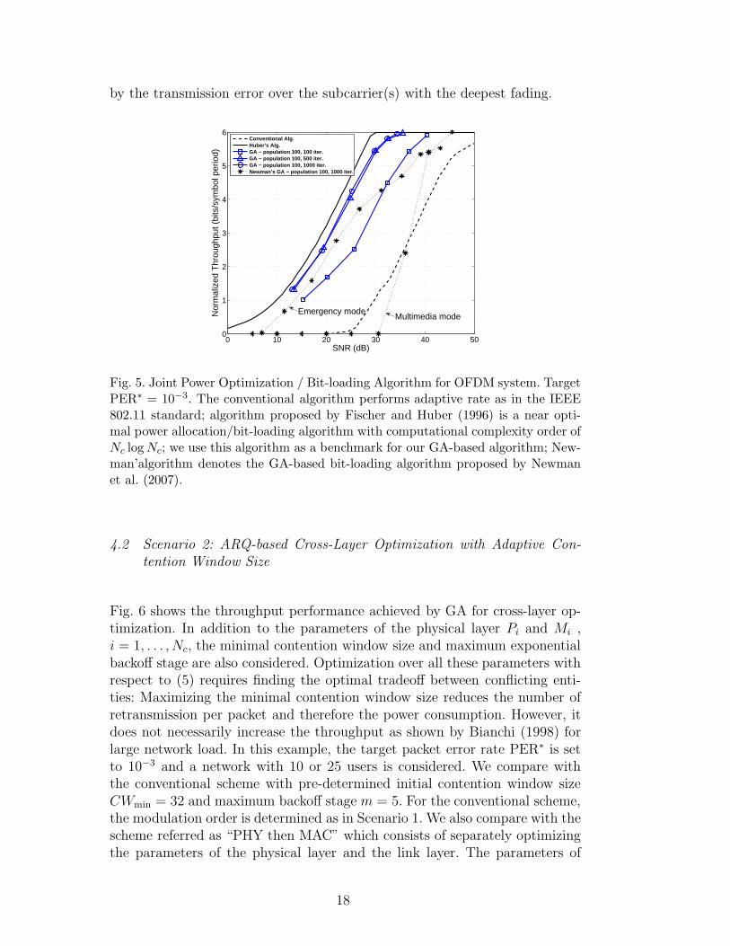
by the transmission error over the subcarrier(s) with the deepest fading.
0 10 20 30 40 500
1
2
3
4
5
6
SNR (dB)
Nor
mal
ized
Thr
ough
put (
bits
/sym
bol p
erio
d)
Conventional Alg.Huber’s Alg.GA − population 100, 100 iter.GA − population 100, 500 iter.GA − population 100, 1000 iter.Newman’s GA − population 100, 1000 iter.
Multimedia modeEmergency mode
Fig. 5. Joint Power Optimization / Bit-loading Algorithm for OFDM system. TargetPER∗ = 10−3. The conventional algorithm performs adaptive rate as in the IEEE802.11 standard; algorithm proposed by Fischer and Huber (1996) is a near opti-mal power allocation/bit-loading algorithm with computational complexity order ofNc log Nc; we use this algorithm as a benchmark for our GA-based algorithm; New-man’algorithm denotes the GA-based bit-loading algorithm proposed by Newmanet al. (2007).
4.2 Scenario 2: ARQ-based Cross-Layer Optimization with Adaptive Con-
tention Window Size
Fig. 6 shows the throughput performance achieved by GA for cross-layer op-timization. In addition to the parameters of the physical layer Pi and Mi ,i = 1, . . . , Nc, the minimal contention window size and maximum exponentialbackoff stage are also considered. Optimization over all these parameters withrespect to (5) requires finding the optimal tradeoff between conflicting enti-ties: Maximizing the minimal contention window size reduces the number ofretransmission per packet and therefore the power consumption. However, itdoes not necessarily increase the throughput as shown by Bianchi (1998) forlarge network load. In this example, the target packet error rate PER∗ is setto 10−3 and a network with 10 or 25 users is considered. We compare withthe conventional scheme with pre-determined initial contention window sizeCWmin = 32 and maximum backoff stage m = 5. For the conventional scheme,the modulation order is determined as in Scenario 1. We also compare with thescheme referred as “PHY then MAC” which consists of separately optimizingthe parameters of the physical layer and the link layer. The parameters of
18
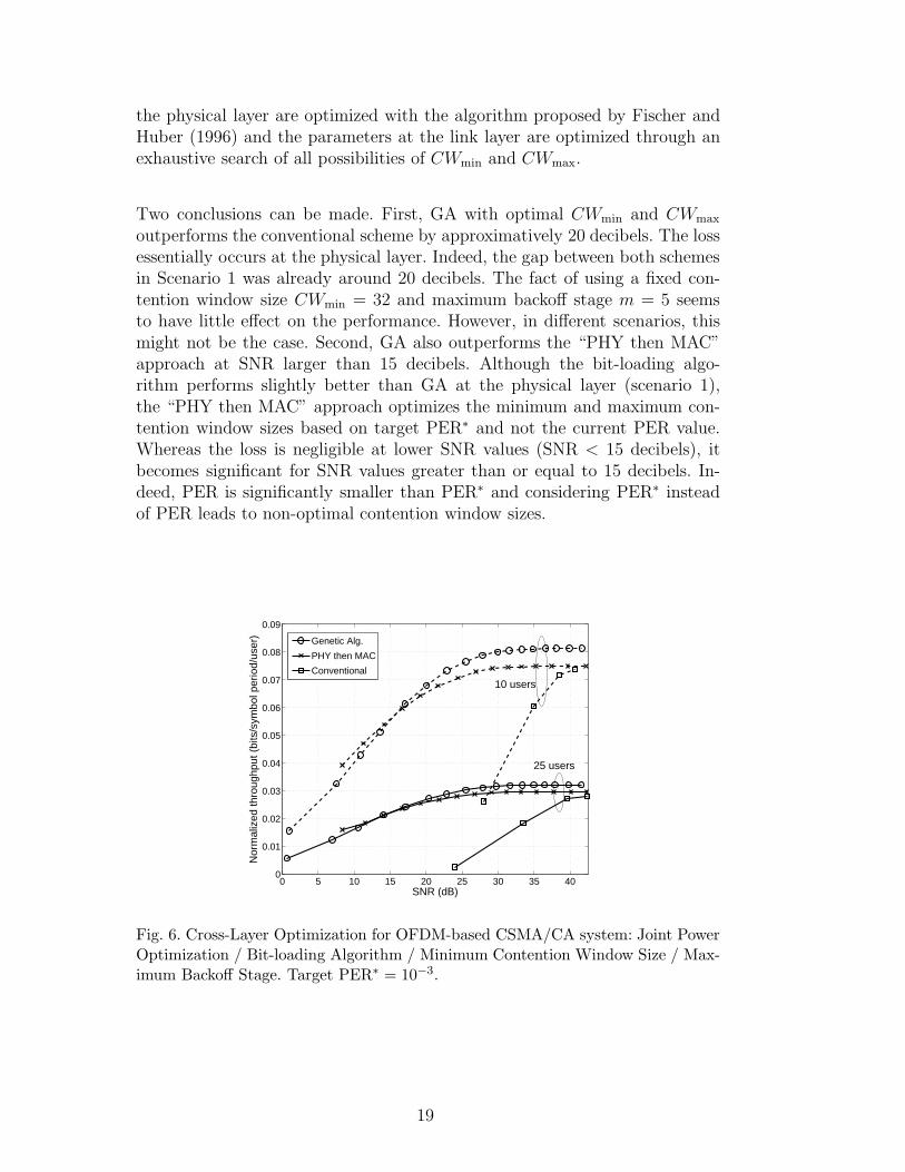
the physical layer are optimized with the algorithm proposed by Fischer andHuber (1996) and the parameters at the link layer are optimized through anexhaustive search of all possibilities of CWmin and CWmax.
Two conclusions can be made. First, GA with optimal CWmin and CWmax
outperforms the conventional scheme by approximatively 20 decibels. The lossessentially occurs at the physical layer. Indeed, the gap between both schemesin Scenario 1 was already around 20 decibels. The fact of using a fixed con-tention window size CWmin = 32 and maximum backoff stage m = 5 seemsto have little effect on the performance. However, in different scenarios, thismight not be the case. Second, GA also outperforms the “PHY then MAC”approach at SNR larger than 15 decibels. Although the bit-loading algo-rithm performs slightly better than GA at the physical layer (scenario 1),the “PHY then MAC” approach optimizes the minimum and maximum con-tention window sizes based on target PER∗ and not the current PER value.Whereas the loss is negligible at lower SNR values (SNR < 15 decibels), itbecomes significant for SNR values greater than or equal to 15 decibels. In-deed, PER is significantly smaller than PER∗ and considering PER∗ insteadof PER leads to non-optimal contention window sizes.
0 5 10 15 20 25 30 35 400
0.01
0.02
0.03
0.04
0.05
0.06
0.07
0.08
0.09
SNR (dB)
Nor
mal
ized
thro
ughp
ut (
bits
/sym
bol p
erio
d/us
er)
Genetic Alg.
PHY then MAC
Conventional
10 users
25 users
Fig. 6. Cross-Layer Optimization for OFDM-based CSMA/CA system: Joint PowerOptimization / Bit-loading Algorithm / Minimum Contention Window Size / Max-imum Backoff Stage. Target PER∗ = 10−3.
19
single hop path
2 hop path
4 hop path
Gateway
Transmitter
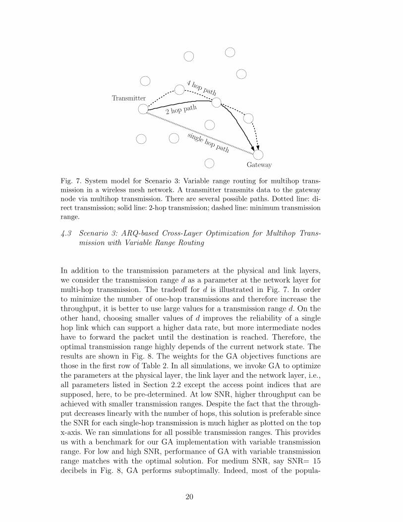
Fig. 7. System model for Scenario 3: Variable range routing for multihop trans-mission in a wireless mesh network. A transmitter transmits data to the gatewaynode via multihop transmission. There are several possible paths. Dotted line: di-rect transmission; solid line: 2-hop transmission; dashed line: minimum transmissionrange.
4.3 Scenario 3: ARQ-based Cross-Layer Optimization for Multihop Trans-
mission with Variable Range Routing
In addition to the transmission parameters at the physical and link layers,we consider the transmission range d as a parameter at the network layer formulti-hop transmission. The tradeoff for d is illustrated in Fig. 7. In orderto minimize the number of one-hop transmissions and therefore increase thethroughput, it is better to use large values for a transmission range d. On theother hand, choosing smaller values of d improves the reliability of a singlehop link which can support a higher data rate, but more intermediate nodeshave to forward the packet until the destination is reached. Therefore, theoptimal transmission range highly depends of the current network state. Theresults are shown in Fig. 8. The weights for the GA objectives functions arethose in the first row of Table 2. In all simulations, we invoke GA to optimizethe parameters at the physical layer, the link layer and the network layer, i.e.,all parameters listed in Section 2.2 except the access point indices that aresupposed, here, to be pre-determined. At low SNR, higher throughput can beachieved with smaller transmission ranges. Despite the fact that the through-put decreases linearly with the number of hops, this solution is preferable sincethe SNR for each single-hop transmission is much higher as plotted on the topx-axis. We ran simulations for all possible transmission ranges. This providesus with a benchmark for our GA implementation with variable transmissionrange. For low and high SNR, performance of GA with variable transmissionrange matches with the optimal solution. For medium SNR, say SNR= 15decibels in Fig. 8, GA performs suboptimally. Indeed, most of the popula-
20
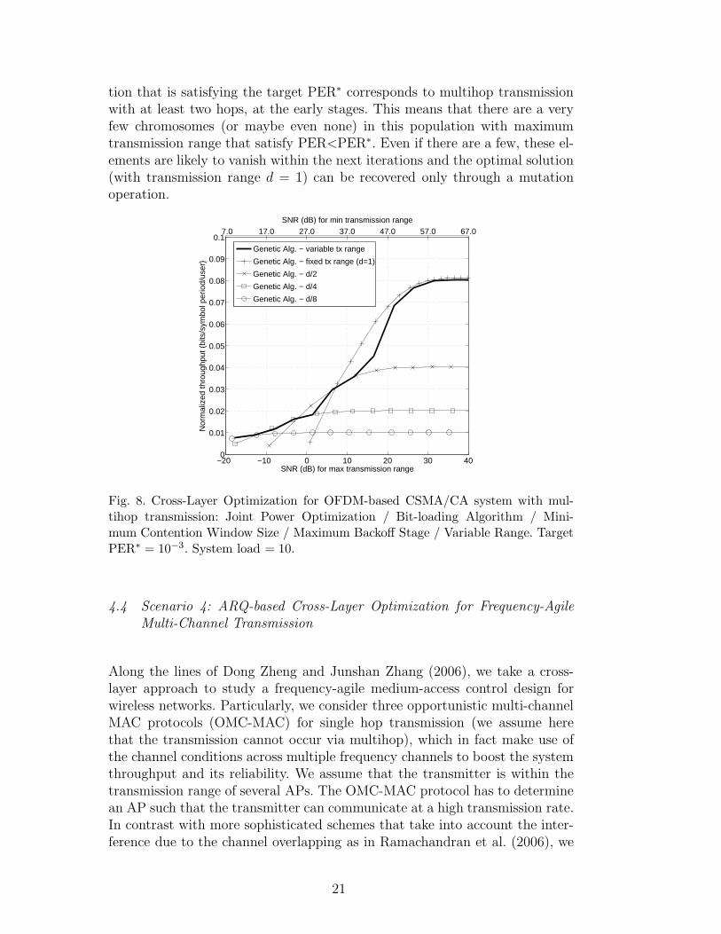
tion that is satisfying the target PER∗ corresponds to multihop transmissionwith at least two hops, at the early stages. This means that there are a veryfew chromosomes (or maybe even none) in this population with maximumtransmission range that satisfy PER<PER∗. Even if there are a few, these el-ements are likely to vanish within the next iterations and the optimal solution(with transmission range d = 1) can be recovered only through a mutationoperation.
7.0 17.0 27.0 37.0 47.0 57.0 67.0SNR (dB) for min transmission range
−20 −10 0 10 20 30 400
0.01
0.02
0.03
0.04
0.05
0.06
0.07
0.08
0.09
0.1
SNR (dB) for max transmission range
Nor
mal
ized
thro
ughp
ut (
bits
/sym
bol p
erio
d/us
er)
Genetic Alg. − variable tx range
Genetic Alg. − fixed tx range (d=1)
Genetic Alg. − d/2
Genetic Alg. − d/4
Genetic Alg. − d/8
Fig. 8. Cross-Layer Optimization for OFDM-based CSMA/CA system with mul-tihop transmission: Joint Power Optimization / Bit-loading Algorithm / Mini-mum Contention Window Size / Maximum Backoff Stage / Variable Range. TargetPER∗ = 10−3. System load = 10.
4.4 Scenario 4: ARQ-based Cross-Layer Optimization for Frequency-Agile
Multi-Channel Transmission
Along the lines of Dong Zheng and Junshan Zhang (2006), we take a cross-layer approach to study a frequency-agile medium-access control design forwireless networks. Particularly, we consider three opportunistic multi-channelMAC protocols (OMC-MAC) for single hop transmission (we assume herethat the transmission cannot occur via multihop), which in fact make use ofthe channel conditions across multiple frequency channels to boost the systemthroughput and its reliability. We assume that the transmitter is within thetransmission range of several APs. The OMC-MAC protocol has to determinean AP such that the transmitter can communicate at a high transmission rate.In contrast with more sophisticated schemes that take into account the inter-ference due to the channel overlapping as in Ramachandran et al. (2006), we
21
TS?
AP1
AP3
AP2
TS
TS
TS
TS
TS
TS
TS
TSTS
TS
TS
TS
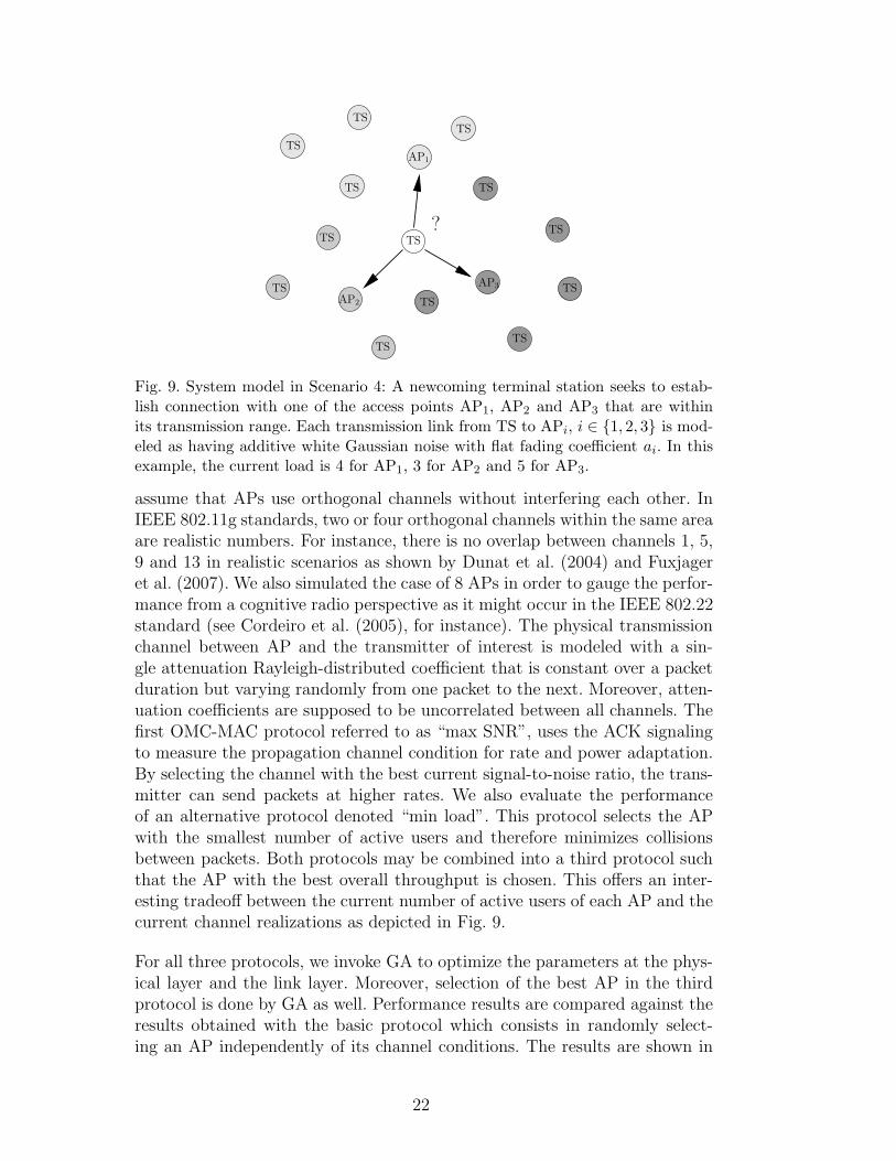
Fig. 9. System model in Scenario 4: A newcoming terminal station seeks to estab-lish connection with one of the access points AP1, AP2 and AP3 that are withinits transmission range. Each transmission link from TS to APi, i ∈ {1, 2, 3} is mod-eled as having additive white Gaussian noise with flat fading coefficient ai. In thisexample, the current load is 4 for AP1, 3 for AP2 and 5 for AP3.
assume that APs use orthogonal channels without interfering each other. InIEEE 802.11g standards, two or four orthogonal channels within the same areaare realistic numbers. For instance, there is no overlap between channels 1, 5,9 and 13 in realistic scenarios as shown by Dunat et al. (2004) and Fuxjageret al. (2007). We also simulated the case of 8 APs in order to gauge the perfor-mance from a cognitive radio perspective as it might occur in the IEEE 802.22standard (see Cordeiro et al. (2005), for instance). The physical transmissionchannel between AP and the transmitter of interest is modeled with a sin-gle attenuation Rayleigh-distributed coefficient that is constant over a packetduration but varying randomly from one packet to the next. Moreover, atten-uation coefficients are supposed to be uncorrelated between all channels. Thefirst OMC-MAC protocol referred to as “max SNR”, uses the ACK signalingto measure the propagation channel condition for rate and power adaptation.By selecting the channel with the best current signal-to-noise ratio, the trans-mitter can send packets at higher rates. We also evaluate the performanceof an alternative protocol denoted “min load”. This protocol selects the APwith the smallest number of active users and therefore minimizes collisionsbetween packets. Both protocols may be combined into a third protocol suchthat the AP with the best overall throughput is chosen. This offers an inter-esting tradeoff between the current number of active users of each AP and thecurrent channel realizations as depicted in Fig. 9.
For all three protocols, we invoke GA to optimize the parameters at the phys-ical layer and the link layer. Moreover, selection of the best AP in the thirdprotocol is done by GA as well. Performance results are compared against theresults obtained with the basic protocol which consists in randomly select-ing an AP independently of its channel conditions. The results are shown in
22
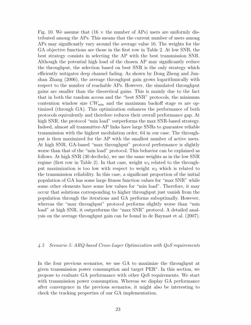
Fig. 10. We assume that (16 × the number of APs) users are uniformly dis-tributed among the APs. This means that the current number of users amongAPs may significantly vary around the average value 16. The weights for theGA objective functions are those in the first row in Table 2. At low SNR, thebest strategy consists in selecting the AP with the best transmission SNR.Although the potential high load of the chosen AP may significantly reducethe throughput, the selection based on best SNR is the only strategy whichefficiently mitigates deep channel fading. As shown by Dong Zheng and Jun-shan Zhang (2006), the average throughput gain grows logarithmically withrespect to the number of reachable APs. However, the simulated throughputgains are smaller than the theoretical gains. This is mainly due to the factthat in both the random access and the “best SNR” protocols, the minimumcontention window size CWmin and the maximum backoff stage m are op-timized (through GA). This optimization enhances the performance of bothprotocols equivalently and therefore reduces their overall performance gap. Athigh SNR, the protocol “min load” outperforms the max SNR-based strategy.Indeed, almost all transmitter-AP links have large SNRs to guarantee reliabletransmission with the highest modulation order, 64 in our case. The through-put is then maximized for the AP with the smallest number of active users.At high SNR, GA-based “max throughput” protocol performance is slightlyworse than that of the “min load” protocol. This behavior can be explained asfollows. At high SNR (30 decibels), we use the same weights as in the low SNRregime (first row in Table 2). In that case, weight w3 related to the through-put maximization is too low with respect to weight w2 which is related tothe transmission reliability. In this case, a significant proportion of the initialpopulation of GA has some large fitness function values for “max SNR” whilesome other elements have some low values for “min load”. Therefore, it mayoccur that solutions corresponding to higher throughput just vanish from thepopulation through the iterations and GA performs suboptimally. However,whereas the “max throughput” protocol performs slightly worse than “minload” at high SNR, it outperforms the “max SNR” protocol. A detailed anal-ysis on the average throughput gain can be found in de Baynast et al. (2007).
4.5 Scenario 5: ARQ-based Cross-Layer Optimization with QoS requirements
In the four previous scenarios, we use GA to maximize the throughput atgiven transmission power consumption and target PER∗. In this section, wepropose to evaluate GA performance with other QoS requirements. We startwith transmission power consumption. Whereas we display GA performanceafter convergence in the previous scenarios, it might also be interesting tocheck the tracking properties of our GA implementation.
23
1 2 3 4 5 6 7 80
10
20
30
40
50
60
70
80
90
100
Number of Access Points
Thr
ough
put G
ain
vs. R
ando
m A
cces
s (%
)
High SNR (30 dB)
Low SNR (10 dB)
Genetic Alg.max SNRmin load
Fig. 10. Comparison between the three protocols for association for the frequen-cy-agile multi-channel system described in Section 4.4: “max SNR” selects the ac-cess point with best SNR, “min load” selects the access point with the lowest loadand the third GA-based protocol “max throughput” selects the access point whichmaximizes the throughput. For all three protocols, cross-Layer optimization is per-formed through GA and includes as parameters: power optimization, bit-loading,minimum Contention window size, maximum backoff stage. Target PER∗ = 10−2
and the average system load per access point is equal to 16.
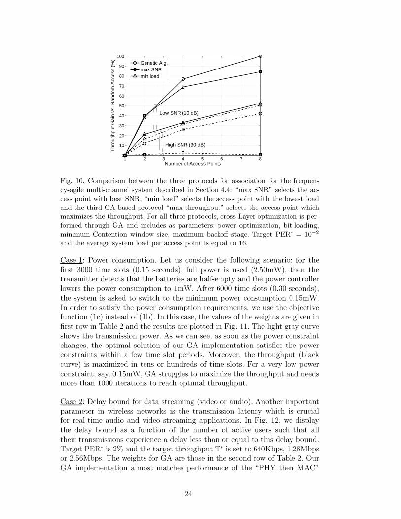
Case 1: Power consumption. Let us consider the following scenario: for thefirst 3000 time slots (0.15 seconds), full power is used (2.50mW), then thetransmitter detects that the batteries are half-empty and the power controllerlowers the power consumption to 1mW. After 6000 time slots (0.30 seconds),the system is asked to switch to the minimum power consumption 0.15mW.In order to satisfy the power consumption requirements, we use the objectivefunction (1c) instead of (1b). In this case, the values of the weights are given infirst row in Table 2 and the results are plotted in Fig. 11. The light gray curveshows the transmission power. As we can see, as soon as the power constraintchanges, the optimal solution of our GA implementation satisfies the powerconstraints within a few time slot periods. Moreover, the throughput (blackcurve) is maximized in tens or hundreds of time slots. For a very low powerconstraint, say, 0.15mW, GA struggles to maximize the throughput and needsmore than 1000 iterations to reach optimal throughput.
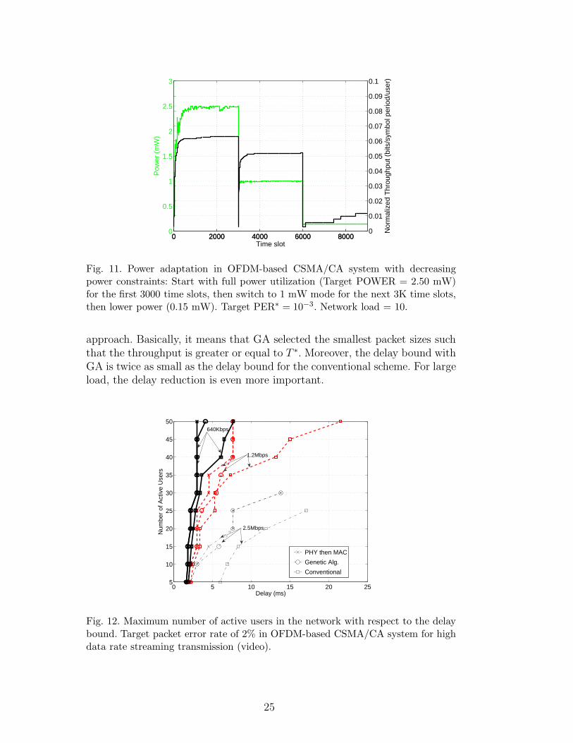
Case 2: Delay bound for data streaming (video or audio). Another importantparameter in wireless networks is the transmission latency which is crucialfor real-time audio and video streaming applications. In Fig. 12, we displaythe delay bound as a function of the number of active users such that alltheir transmissions experience a delay less than or equal to this delay bound.Target PER∗ is 2% and the target throughput T∗ is set to 640Kbps, 1.28Mbpsor 2.56Mbps. The weights for GA are those in the second row of Table 2. OurGA implementation almost matches performance of the “PHY then MAC”
24
0 2000 4000 6000 80000
0.5
1
1.5
2
2.5
3
Time slot
Pow
er (
mW
)
0 2000 4000 6000 80000
0.01
0.02
0.03
0.04
0.05
0.06
0.07
0.08
0.09
0.1
Nor
mal
ized
Thr
ough
put (
bits
/sym
bol p
erio
d/us
er)
Fig. 11. Power adaptation in OFDM-based CSMA/CA system with decreasingpower constraints: Start with full power utilization (Target POWER = 2.50 mW)for the first 3000 time slots, then switch to 1 mW mode for the next 3K time slots,then lower power (0.15 mW). Target PER∗ = 10−3. Network load = 10.
approach. Basically, it means that GA selected the smallest packet sizes suchthat the throughput is greater or equal to T ∗. Moreover, the delay bound withGA is twice as small as the delay bound for the conventional scheme. For largeload, the delay reduction is even more important.
0 5 10 15 20 255
10
15
20
25
30
35
40
45
50
Delay (ms)
Num
ber
of A
ctiv
e U
sers
PHY then MAC
Genetic Alg.
Conventional
640Kbps
1.2Mbps
2.5Mbps
Fig. 12. Maximum number of active users in the network with respect to the delaybound. Target packet error rate of 2% in OFDM-based CSMA/CA system for highdata rate streaming transmission (video).
25
5 Conclusion
We have addressed cross-layer optimization for wireless multicarrier systemsin the context of cognitive radios and cognitive radio networks. Optimizationinvolves search over large discrete spaces. Traditionally, this optimization re-quires full or partial network state information at the transmitter. In this work,we invoked a genetic algorithm to perform this optimization. We showed thatthe optimal transmission parameters can be iteratively determined with theacknowledgment signaling of the prior transmitted packets as the lone externalinput. No other network state information is required, and the fact that weare able to piggyback the information over ACK signaling makes the solutionattractive as no separate signaling channel is required. Moreover, the opti-mization process does not require any transmission model. Simulations with alarge variety of QoS requirements validated our approach. Simulation resultsshowed that our ACK signal-based GA implementation achieves comparableperformance to an exhaustive search over the whole set of parameters whichrequires perfect network state information at the transmitter.
The results show that GA-based cognitive methods can provide true benefitsin the context of wireless communication networks. Future work requires moreextensive studies with large-scale networks. In that domain we are currentlyexperimenting not only with simulations, but also by using gnuRadio-basedtestbeds. One of the main benefits of our method is that it can concurrentlyand dynamically handle optimization towards different goals, and it does notrequire complex exchange of network state information. As future research,we are also considering issues of overall network capacity constraints and un-derstanding the limits of VPI.
Acknowledgments
This work has been in part supported by DFG (Deutsche Forschungsgemein-schaft) and RWTH Aachen University through the UMIC excellence clusterfunding.
References
Baldo, N., Zorzi, M., June 2007. Cognitive Network Access using Fuzzy De-cision Making. In: Proceedings of the IEEE CogNet 2007 Workshop (inconjunction with IEEE ICC 2007), Glasgow, UK.
Bianchi, G., Dec. 1998. IEEE 802.11-saturation throughput analysis. IEEECommunications Letters 2, 318–320.
26
Buddhikot, M., April 2007. Understanding Dynamic Spectrum Access: Tax-onomy, Models and Challenges. In: Proceedings of the IEEE InternationalSymposium on New Frontiers in Dynamic Spectrum Access Networks (DyS-PAN). pp. 649–663.
Cordeiro, C., Challapali, K., Birru, D., Sai Shankar, Nov. 2005. IEEE 802.22:the first worldwide wireless standard based on cognitive radios. In: Proceed-ings of the 1st IEEE International Symposium on New Frontiers in DynamicSpectrum Access Networks (DySPAN). pp. 328–337.
de Baynast, A., Wu, L., Mahonen, P., 2007. Frequency-Agile Multi-ChannelMedium Access Control: Efficient Protocols and Outage Behavior, submit-ted to IEEE International Conference on Communications.
Dong Zheng, Junshan Zhang, Oct. 2006. Protocol design and throughput anal-ysis of frequency-agile multi-channel medium access control. IEEE Trans-actions on Wireless Communications 5, 2887–2895.
Dunat, J., Elicegui, L., Bonnet, C., Sep. 2004. Impact of inter-cell interfer-ence in a IEEE 802.11a network with overlapping cells. In: Proceedings ofthe IEEE International Symposium on Personal, Indoor and Mobile RadioCommunications (PIMRC). Vol. 2. pp. 825–829.
Fischer, R., Huber, J., 1996. A new loading algorithm for discrete multitonetransmission. In: Proceedings of the IEEE Global Telecommunications Con-ference (GLOBECOM). Vol. 1. pp. 724–728.
Fonseca, C., Fleming, P., Jan. 1998a. Multi-objective optimization and mul-tiple constraint handling with evolutionary algorithms. I. A unified formu-lation. IEEE Transactions on Systems, Man and Cybernetics, Part A 28,26–37.
Fonseca, C., Fleming, P., Jan. 1998b. Multi-objective optimization and mul-tiple constraint handling with evolutionary algorithms. II. Application ex-ample. IEEE Transactions on Systems, Man and Cybernetics, Part A 28,38–47.
Fuxjager, P., Valerio, D., Ricciato, F., Jan. 2007. The myth of non-overlappingchannels: interference measurements in IEEE 802.11. In: Proceedings of theConference on Wireless on Demand Network Systems and Services (WONS).pp. 1–8.
IEEE 802.11, 1999. IEEE 802.11-1999. Tech. rep., In-stitute of Electrical and Electronics Engineers, Avail-able: http://standards.ieee.org/getieee802/802.11.html.
Johansson, B., Soldati, P., Johansson, M., Aug. 2006. Mathematical Decom-position Techniques for Distributed Cross-Layer Optimization of Data Net-works. IEEE Journal on Selected Areas in Communications 24 (8), 1535–1547.
Kawadia, V., Kumar, P., Feb. 2005. A cautionary perspective on cross-layerdesign. IEEE Personal Communications 12 (1), 3–11.
Mahonen, P., Sep 2004. Cognitive Trends in Making: future of networks. In:Proceedings of the IEEE International Symposium on Personal, Indoor andMobile Radio Communications (PIMRC). pp. 1449 – 1454.
27
Minden, G., Evans, J. B., Searl, L., DePardo, D., Petty, V. R., Rajbanshi,R., Newman, T., Chen, Q., Weidling, F., Guffey, J., Datla, D., Barker, B.,Peck, M., Cordill, B., Wyglinski, A. M., Agah, A., April 2007. KUAR: AFlexible Software-Defined Radio Development Platform. In: Proceedings ofthe IEEE International Symposium on New Frontiers in Dynamic SpectrumAccess Networks (DySPAN).
Mitola, J., 2000. Cognitive Radio: An Integrated Agent Architecture for Soft-ware Defined Radio. Ph.D. Thesis, KTH (Royal Institute of Technology).
Mitola, III, J., Maguire, Jr., G., 1999. Cognitive radio: Making software radiosmore personal. IEEE Personal Communications 6 (4).
Mung Chiang, Low, S., Calderbank, A., Doyle, J., Jan. 2007. Layering as Opti-mization Decomposition: A Mathematical Theory of Network Architectures.Proceedings of the IEEE 95 (1), 255–312.
Newman, T., Barker, B., Wyglinski, A., Agah, A., Evans, J., Minden, G.,May 2007. Cognitive Engine Implementation for Wireless MulticarrierTransceivers, Wiley Wireless Communications and Mobile Computing Edi-tion.
Nolan, K., Doyle, L., Aug. 2007. Teamwork and Collaboration in CognitiveWireless Networks. IEEE Wireless Communications, 22 – 27.
Petrova, M., Mahonen, P., 2007a. Cognitive Resource Manager: A cross-layerarchitecture for implementing Cognitive Radio Networks. Cognitive Wire-less Networks (eds. Fittzek F. and Katz M.), Springer.
Petrova, M., Mahonen, P., June 2007b. Evolution of radio resource manage-ment: A case for cognitive resource manager. In: Proceedings of the IEEEInternational Conference on Communications (ICC). pp. 6471–6745.
Petrova, M., Mahonen, P., Riihijarvi, J., Wellens, M., April 2006. CognitiveWireless Networks: Your Network Just Became a Teenager. In: Poster ses-sion of the IEEE International Conference on Computer Communications(INFOCOM).
Ramachandran, K., Belding, E., Almeroth, K., Buddhikot, M., April 2006.Interference-Aware Channel Assignment in Multi-Radio Wireless Mesh Net-works. In: Proceedings of the IEEE International Conference on ComputerCommunications (INFOCOM). pp. 1–12.
Rieser, C., 2004. Biologically Inspired Cognitive Radio Engine Model UtilizingDistributed Genetic Algorithms for Secure and Robust Wireless Communi-cations and Networking. Ph.D. Thesis, Virginia Tech.
Sonalkar, R., Shively, R., March 2000. An efficient bit-loading algorithm forDMT applications. IEEE Communications Letters 4, 80–82.
Song, G.-C., Li, Y., March 2005. Cross-layer optimization for OFDM wirelessnetworks Part I: theoretical framework. IEEE Transactions on WirelessCommunications 4, 614–624.
Sutton, P., Doyle, L., Nolan, K., June 2006. A Reconfigurable Platform forCognitive Networks. In: Proceedings of the International Conference on Cog-nitive Radio Oriented Wireless Networks and Communications (CROWN-COM). pp. 1–5.
28
Thomas, R., DaSilva, L., MacKenzie, A. B., Nov 2005. Cognitive Networks.In: Proceedings of the IEEE International Symposium on New Frontiers inDynamic Spectrum Access Networks (DySPAN). pp. 352 – 360.
Thomas, R., Friend, D., DaSilva, L., MacKenzie, A. B., Dec. 2006. CognitiveNetworks: Adaptation and Learning to Achieve End-to-end PerformanceObjectives. IEEE Communications Magazine 44 (12), 51 – 57.
Thomas, R. W., DaSilva, L., Marathe, M., Wood, K. N., June 2007. Crit-ical design decisions for cognitive networks. In: Proceedings of the IEEEInternational Conference on Communications (ICC). pp. 3993–3998.
Whitley, D., 1994. A Genetic Algorithm Tutorial. Statistics and Computing4, 65–85.
Ying Jun Zhang, Letaief, K., Nov. 2006. Cross-layer adaptive resource manage-ment for wireless packet networks with ofdm signaling. IEEE Transactionson Wireless Communications 5 (11), 3244–3254.
29