
ARMY 19.2 Small Business Innovation Research (SBIR ... · ARMY-1 ARMY 19.2 Small Business...
67
ARMY-1 ARMY 19.2 Small Business Innovation Research (SBIR) Proposal Submission Instructions INTRODUCTION The U.S. Army Combat Capabilities Development Command (CCDC) is responsible for execution of the Army SBIR Program. Information on the Army SBIR Program can be found at the following Website: https://www.armysbir.army.mil/. Broad Agency Announcement (BAA), topic, and general questions regarding the SBIR Program should be addressed according to the DoD Program BAA. For technical questions about the topic during the pre- release period, contact the Topic Authors listed for each topic in the BAA. To obtain answers to technical questions during the formal BAA period, visit https://sbir.defensebusiness.org/. Specific questions pertaining to the Army SBIR Program should be submitted to: Monroe Harden Acting Program Manager, Army SBIR [email protected] U.S. Army Combat Capabilities Development Command 6662 Gunner Circle Aberdeen Proving Ground, MD 21005-1322 TEL: 866-570-7247 The Army participates in three DoD SBIR BAAs each year. Proposals not conforming to the terms of this BAA will not be considered. Only Government personnel will evaluate proposals with the exception of technical personnel from Cherokee Nation Technology Solutions and Georgia Tech Research Institute who will provide Advisory and Assistance Services to the Army and technical analysis in the evaluation of proposals submitted against Army topic numbers: A19-124 “A point-of-care assay to determine soldier dengue exposure and enable rapid, mass, cost-efficient dengue vaccination programs of military personnel” (Cherokee Nation Technology Solutions) A19-131“Reduced emission sensors for Short Range Air Defense (SHORAD)” (Georgia Tech Research Institute) The individuals from Cherokee Nation Technology Solutions and Georgia Tech Research Institute will be authorized access to only those portions of the proposal data and discussions that are necessary to enable them to perform their respective duties. These institutions are expressly prohibited from competing for SBIR awards and from scoring or ranking of proposals or recommending the selection of a source. In accomplishing their duties related to the selection processes, the aforementioned institutions may require access to proprietary information contained in the offerors’ proposals. Therefore, pursuant to FAR 9.505-4, the institutions must execute an agreement that states that they will (1) protect the offerors’ information from unauthorized use or disclosure for as long as it remains proprietary and (2) refrain from using the information for any purpose other than that for which it was furnished. These agreements will remain on file with the Army SBIR program management office at the address above.
Transcript of ARMY 19.2 Small Business Innovation Research (SBIR ... · ARMY-1 ARMY 19.2 Small Business...

ARMY-1
ARMY
19.2 Small Business Innovation Research (SBIR)
Proposal Submission Instructions
INTRODUCTION
The U.S. Army Combat Capabilities Development Command (CCDC) is responsible for execution of the
Army SBIR Program. Information on the Army SBIR Program can be found at the following Website:
https://www.armysbir.army.mil/.
Broad Agency Announcement (BAA), topic, and general questions regarding the SBIR Program should
be addressed according to the DoD Program BAA. For technical questions about the topic during the pre-
release period, contact the Topic Authors listed for each topic in the BAA. To obtain answers to technical
questions during the formal BAA period, visit https://sbir.defensebusiness.org/. Specific questions
pertaining to the Army SBIR Program should be submitted to:
Monroe Harden
Acting Program Manager, Army SBIR
U.S. Army Combat Capabilities Development Command
6662 Gunner Circle
Aberdeen Proving Ground, MD 21005-1322
TEL: 866-570-7247
The Army participates in three DoD SBIR BAAs each year. Proposals not conforming to the terms of
this BAA will not be considered. Only Government personnel will evaluate proposals with the exception
of technical personnel from Cherokee Nation Technology Solutions and Georgia Tech Research Institute
who will provide Advisory and Assistance Services to the Army and technical analysis in the evaluation
of proposals submitted against Army topic numbers:
A19-124 “A point-of-care assay to determine soldier dengue exposure and enable rapid,
mass, cost-efficient dengue vaccination programs of military personnel” (Cherokee
Nation Technology Solutions)
A19-131“Reduced emission sensors for Short Range Air Defense (SHORAD)” (Georgia
Tech Research Institute)
The individuals from Cherokee Nation Technology Solutions and Georgia Tech Research
Institute will be authorized access to only those portions of the proposal data and discussions that
are necessary to enable them to perform their respective duties. These institutions are expressly
prohibited from competing for SBIR awards and from scoring or ranking of proposals or
recommending the selection of a source. In accomplishing their duties related to the selection
processes, the aforementioned institutions may require access to proprietary information
contained in the offerors’ proposals. Therefore, pursuant to FAR 9.505-4, the institutions must
execute an agreement that states that they will (1) protect the offerors’ information from
unauthorized use or disclosure for as long as it remains proprietary and (2) refrain from using the
information for any purpose other than that for which it was furnished. These agreements will
remain on file with the Army SBIR program management office at the address above.
ARMY-2
PHASE I PROPOSAL SUBMISSION
SBIR Phase I proposals have four Volumes: Proposal Cover Sheet, Technical Volume, Cost Volume
and Company Commercialization Report. Please note that the Army will not be accepting a
Volume Five (Supporting Documents), nor a Volume Six (Fraud, Waste and Abuse) as noted at
the DoD SBIR website. The Technical Volume .pdf document has a 20-page limit including: table of
contents, pages intentionally left blank, references, letters of support, appendices, technical portions
of subcontract documents (e.g., statements of work and resumes) and any other attachments. Small
businesses submitting a Phase I Proposal must use the DoD SBIR electronic proposal submission
system (https://sbir.defensebusiness.org/). This site contains step-by-step instructions for the
preparation and submission of the Proposal Cover Sheet, the Company Commercialization Report,
the Cost Volume, and how to upload the Technical Volume. For general inquiries or problems with
proposal electronic submission, contact the DoD SBIR Help Desk at 1-800-348-0787.
The small business will also need to register at the Army SBIR Small Business website:
https://portal.armysbir.army.mil/Portal/SmallBusinessPortal/Default.aspx in order to receive
information regarding proposal status/debriefings, summary reports, impact/transition stories, and
Phase III plans. PLEASE NOTE: If this is your first time submitting an Army SBIR proposal, you
will not be able to register your firm at the Army SBIR Small Business website until after all of the
proposals have been downloaded and we have transferred your company information to the Army
Small Business website. This can take up to one week after the end of the proposal submission
period.
Do not include blank pages, duplicate the electronically generated cover pages or put information
normally associated with the Technical Volume such as descriptions of capability or intent in other
sections of the proposal as these will count toward the 20-page limit.
Only the electronically generated Cover Sheets, Cost Volume and Company Commercialization
Report (CCR) are excluded from the 20-page limit. The CCR is generated by the proposal
submission website, based on information provided by you through the Company Commercialization
Report tool. Army Phase I proposals submitted containing a Technical Volume .pdf document
containing over 20 pages will be deemed NON-COMPLIANT and will not be evaluated. It is the
responsibility of the Small Business to ensure that once the proposal is submitted and uploaded
into the system that the technical volume .pdf document complies with the 20 page limit.
Phase I proposals must describe the "vision" or "end-state" of the research and the most likely strategy or
path for transition of the SBIR project from research to an operational capability that satisfies one or more
Army operational or technical requirements in a new or existing system, larger research program, or as a
stand-alone product or service.
Phase I proposals will be reviewed for overall merit based upon the criteria in Section 6.0 of the DoD
Program BAA.
PHASE I OPTION MUST BE INCLUDED AS PART OF PHASE I PROPOSAL
The Army implements the use of a Phase I Option that may be exercised to fund interim Phase I activities
while a Phase II contract is being negotiated. Only Phase I efforts selected for Phase II awards through
the Army’s competitive process will be eligible to have the Phase I Option exercised. The Phase I
Option, which must be included as part of the Phase I proposal, should cover activities over a period of

ARMY-3
up to four months and describe appropriate initial Phase II activities that may lead to the successful
demonstration of a product or technology. The Phase I Option must be included within the 20-page limit
for the Phase I proposal. Do not include blank pages, duplicate the electronically generated cover pages
or put information normally associated with the Technical Volume such as descriptions of capability or
intent, in other sections of the proposal as these will count toward the 20 page limit.
PHASE I COST VOLUME
A firm fixed price or cost plus fixed fee Phase I Cost Volume ($167,500 maximum-PLEASE NOTE
THAT THE MAXIMUM DOLLAR AMOUNT HAS BEEN INCREASED COMPARED TO
PREVIOUS PHASE I’s) must be submitted in detail online. Proposers that participate in this BAA must
complete a Phase I Cost Volume not to exceed a maximum dollar amount of $111,500 for the six months
base period and a Phase I Option Cost Volume not to exceed a maximum dollar amount of $56,000 for
the four months option period (PLEASE NOTE THESE DOLLAR AMOUNTS HAVE BEEN
INCREASED COMPARED TO PREVIOUS PHASE I’s). The Phase I and Phase I Option costs must
be shown separately but may be presented side-by-side in a single Cost Volume. The Cost Volume
DOES NOT count toward the 20-page Phase I proposal limitation when submitted via the submission
site’s on-line form. When submitting the Cost Volume, complete the Cost Volume form on the DoD
Submission site, versus submitting it within the body of the uploaded proposal.
PHASE II PROPOSAL SUBMISSION
Commencing with Phase II’s resulting from a 13.1 Phase I, invitations are no longer required. Small businesses submitting a Phase II Proposal must use the DoD SBIR electronic proposal
submission system (https://sbir.defensebusiness.org/). This site contains step-by-step instructions for
the preparation and submission of the Proposal Cover Sheet, the Company Commercialization
Report, the Cost Volume, and how to upload the Technical Volume. For general inquiries or
problems with proposal electronic submission, contact the DoD Help Desk at 1-800-348-0787.
Army SBIR has four cycles in each FY for Phase II submission. A single Phase II proposal can be
submitted by a Phase I awardee within one, and only one, of four submission cycles and must be
submitted between 4 to 17 months after the Phase I contract award date. Any proposals that are not
submitted within these four submission cycles and before 4 months or after 17 months from the
contract award date will not be evaluated. The submission window opens at 0001hrs (12:01 AM)
eastern time on the first day and closes at 2359 hrs (11:59 PM) eastern time on the last day. Any
subsequent Phase II proposal (i.e., a second Phase II subsequent to the initial Phase II effort) shall be
initiated by the Government Technical Point of Contact for the initial Phase II effort and must be
approved by Army SBIR PM in advance.
The four Phase II submission cycles following the announcement of selections for the 19.2 BAA are:
2020(b) 2 Mar – 1 Apr 2020
2020(c) 15 Jun – 15 Jul 2020
2020(d) 3 Aug - 4 Sep 2020
2021(a) 15 Oct – 15 Nov 2020
For other submission cycles see the schedule below, and always check with the Army SBIR Program
Managers Office helpdesk for the exact dates.

ARMY-4
SUBMISSION CYCLES TIMEFRAME
Cycle One 30 calendar days starting on or about 15 October*
Cycle Two 30 calendar days starting on or about 1 March*
Cycle Three 30 calendar days starting on or about 15 June*
Cycle Four 30 calendar days starting on or about 1 August*
*Submission cycles will open on the date listed unless it falls on a weekend or a Federal Holiday. In
those cases, it will open on the next available business day.
Army SBIR Phase II Proposals have four Volumes: Proposal Cover Sheet, Technical Volume, Cost
Volume and Company Commercialization Report. The Technical Volume .pdf document has a 38-page
limit including: table of contents, pages intentionally left blank, references, letters of support,
appendices, technical portions of subcontract documents (e.g., statements of work and resumes), data
assertions and any attachments. Do not include blank pages, duplicate the electronically generated cover
pages or put information normally associated with the Technical Volume in other sections of the
proposal as these will count toward the 38 page limit. As with Phase I proposals, it is the proposing
firm’s responsibility to verify that the Technical Volume .pdf document does not exceed the page limit
after upload to the DoD SBIR/STTR Submission site by clicking on the “Verify Technical Volume”
icon.
Only the electronically generated Cover Sheet, Cost Volume and Company Commercialization Report
(CCR) are excluded from the 38-page Technical Volume. The CCR is generated by the proposal
submission website, based on information provided by you through the Company Commercialization
Report tool.
Army Phase II Proposals submitted containing a Technical Volume .pdf document over 38 pages
will be deemed NON-COMPLIANT and will not be evaluated.
Army Phase II Cost Volumes must contain a budget for the entire 24 month Phase II period not to exceed
the maximum dollar amount of $1,100,000 (PLEASE NOTE THAT THIS DOLLAR AMOUNT HAS
BEEN INCREASED COMPARED TO PREVIOUS PHASE II’s). During contract negotiation, the
contracting officer may require a Cost Volume for year one and year two. The proposal cost volumes
must be submitted using the Cost Volume format (accessible electronically on the DoD submission site),
and may be presented side-by-side on a single Cost Volume Sheet. The total proposed amount should be
indicated on the Proposal Cover Sheet as the Proposed Cost. Phase II projects will be evaluated after the
first year prior to extending funding for the second year.
Small businesses submitting a proposal are required to develop and submit a technology transition and
commercialization plan describing feasible approaches for transitioning and/or commercializing the
developed technology in their Phase II proposal.
DoD is not obligated to make any awards under Phase I, II, or III. For specifics regarding the evaluation
and award of Phase I or II contracts, please read the DoD Program BAA very carefully. Phase II
proposals will be reviewed for overall merit based upon the criteria in Section 8.0 of the BAA.
BIO HAZARD MATERIAL AND RESEARCH INVOLVING ANIMAL OR HUMAN SUBJECTS

ARMY-5
Any proposal involving the use of Bio Hazard Materials must identify in the Technical Volume whether
the contractor has been certified by the Government to perform Bio Level - I, II or III work.
Companies should plan carefully for research involving animal or human subjects, or requiring access to
government resources of any kind. Animal or human research must be based on formal protocols that are
reviewed and approved both locally and through the Army's committee process. Resources such as
equipment, reagents, samples, data, facilities, troops or recruits, and so forth, must all be arranged
carefully. The few months available for a Phase I effort may preclude plans including these elements,
unless coordinated before a contract is awarded.
FOREIGN NATIONALS
If the offeror proposes to use a foreign national(s) [any person who is NOT a citizen or national of the
United States, a lawful permanent resident, or a protected individual as defined by 8 U.S.C. 1324b (a) (3)
– refer to Section 3.5 of this BAA for definitions of “lawful permanent resident” and “protected
individual”] as key personnel, they must be clearly identified. For foreign nationals, you must provide
country of origin, the type of visa or work permit under which they are performing and an
explanation of their anticipated level of involvement on this project. Please ensure no Privacy Act
information is included in this submittal.
OZONE CHEMICALS
Class 1 Ozone Depleting Chemicals/Ozone Depleting Substances are prohibited and will not be allowed
for use in this procurement without prior Government approval.
CONTRACTOR MANPOWER REPORTING APPLICATION (CMRA)
The Contractor Manpower Reporting Application (CMRA) is a Department of Defense Business
Initiative Council (BIC) sponsored program to obtain better visibility of the contractor service workforce.
This reporting requirement applies to all Army SBIR contracts.
Offerors are instructed to include an estimate for the cost of complying with CMRA as part of the Cost
Volume for Phase I ($111,500 maximum), Phase I Option ($56,000 maximum), and Phase II
($1,100,000 maximum), under “CMRA Compliance” in Other Direct Costs. This is an estimated total
cost (if any) that would be incurred to comply with the CMRA requirement. Only proposals that receive
an award will be required to deliver CMRA reporting, i.e. if the proposal is selected and an award is
made, the contract will include a deliverable for CMRA.
To date, there has been a wide range of estimated costs for CMRA. While most final negotiated costs
have been minimal, there appears to be some higher cost estimates that can often be attributed to
misunderstanding the requirement. The SBIR Program desires for the Government to pay a fair and
reasonable price. This technical analysis is intended to help determine this fair and reasonable price for
CMRA as it applies to SBIR contracts.
The Office of the Assistant Secretary of the Army (Manpower & Reserve Affairs) operates and
maintains the secure CMRA System. The CMRA Web site is located here: https://www.ecmra.mil/.
The CMRA requirement consists of the following items, which are located within the contract
document, the contractor's existing cost accounting system (i.e. estimated direct labor hours,

ARMY-6
estimated direct labor dollars), or obtained from the contracting officer representative:
(1) Contract number, including task and delivery order number;
(2) Contractor name, address, phone number, e-mail address, identity of contractor employee
entering data;
(3) Estimated direct labor hours (including sub-contractors);
(4) Estimated direct labor dollars paid this reporting period (including sub-contractors);
(5) Predominant Federal Service Code (FSC) reflecting services provided by contractor (and
separate predominant FSC for each sub-contractor if different);
(6) Organizational title associated with the Unit Identification Code (UIC) for the Army
Requiring Activity (The Army Requiring Activity is responsible for providing the contractor
with its UIC for the purposes of reporting this information);
(7) Locations where contractor and sub-contractors perform the work (specified by zip code in
the United States and nearest city, country, when in an overseas location, using standardized
nomenclature provided on Web site);
The reporting period will be the period of performance not to exceed 12 months ending September
30 of each government fiscal year and must be reported by 31 October of each calendar year.
According to the required CMRA contract language, the contractor may use a direct XML data
transfer to the Contractor Manpower Reporting System database server or fill in the fields on the
Government Web site. The CMRA Web site also has a no-cost CMRA XML Converter Tool.
Given the small size of our SBIR contracts and companies, it is our opinion that the modification of
contractor payroll systems for automatic XML data transfer is not in the best interest of the Government.
CMRA is an annual reporting requirement that can be achieved through multiple means to include manual
entry, MS Excel spreadsheet development, or use of the free Government XML converter tool. The
annual reporting should take less than a few hours annually by an administrative level employee.
Depending on labor rates, we would expect the total annual cost for SBIR companies to not exceed
$500.00 annually, or to be included in overhead rates.
DISCRETIONARY TECHNICAL AND BUSINESS ASSISTANCE (TABA) (FORMERLY
KNOWN AS DISCRETIONARY TECHNICAL ASSISTANCE)
In accordance with section 9(q) of the Small Business Act (15 U.S.C. 638(q)), the Army will provide
technical assistance services to small businesses engaged in SBIR projects through a network of scientists
and engineers engaged in a wide range of technologies. The objective of this effort is to increase Army
SBIR technology transition and commercialization success thereby accelerating the fielding of
capabilities to Soldiers and to benefit the nation through stimulated technological innovation, improved
manufacturing capability, and increased competition, productivity, and economic growth.
The Army has stationed nine Technical Assistance Advocates (TAAs) across the Army to provide
technical assistance to small businesses that have Phase I and Phase II projects with the participating
organizations within their regions.
For more information go to: https://www.armysbir.army.mil, then click the “SBIR” tab, and then
click on Transition Assistance/Technical Assistance.
As noted in Section 4.22 of the DoD Program BAA, firms may request technical assistance from sources
other than those provided by the Army. All such requests must be made in accordance with the

ARMY-7
instructions in Section 4.22. It should also be noted that if approved for discretionary technical and
business assistance from an outside source, the firm will not be eligible for the Army’s Technical
Assistance Advocate support. All details of the TABA agency and what services they will provide must
be listed in the technical proposal under “consultants”. The request for TABA must include details on
what qualifies the TABA firm to provide the services that you are requesting, the firm name, a point of
contact for the firm, and a web site for the firm. List all services that the firm will provide and why they
are uniquely qualified to provide these services. The award of TABA funds is not automatic and must be
approved by the Army SBIR Program Manager. The maximum TABA dollar amount that can be
requested in a Phase I Army SBIR proposal is $5,000. The maximum TABA dollar amount that can be
requested in a Phase II Army SBIR proposal is $5,000 per year (for a total of $10,000 for two years).
COMMERCIALIZATION READINESS PROGRAM (CRP)
The objective of the CRP effort is to increase Army SBIR technology transition and commercialization
success and accelerate the fielding of capabilities to Soldiers. The CRP: 1) assesses and identifies SBIR
projects and companies with high transition potential that meet high priority requirements; 2) matches
SBIR companies to customers and facilitates collaboration; 3) facilitates detailed technology transition
plans and agreements; 4) makes recommendations for additional funding for select SBIR projects that
meet the criteria identified above; and 5) tracks metrics and measures results for the SBIR projects within
the CRP.
Based on its assessment of the SBIR project’s potential for transition as described above, the Army
utilizes a CRP investment fund of SBIR dollars targeted to enhance ongoing Phase II activities with
expanded research, development, test and evaluation to accelerate transition and commercialization. The
CRP investment fund must be expended according to all applicable SBIR policy on existing Phase II
availability of matching funds, proposed transition strategies, and individual contracting arrangements.
NON-PROPRIETARY SUMMARY REPORTS
All award winners must submit a non-proprietary summary report at the end of their Phase I project and
any subsequent Phase II project. The summary report is unclassified, non-sensitive and non-proprietary
and should include:
A summation of Phase I results
A description of the technology being developed
The anticipated DoD and/or non-DoD customer
The plan to transition the SBIR developed technology to the customer
The anticipated applications/benefits for government and/or private sector use
An image depicting the developed technology
The non-proprietary summary report should not exceed 700 words, and is intended for public viewing on
the Army SBIR/STTR Small Business area. This summary report is in addition to the required final
technical report and should require minimal work because most of this information is required in the final
technical report. The summary report shall be submitted in accordance with the format and instructions
posted within the Army SBIR Small Business Portal at:
https://portal.armysbir.army.mil/Portal/SmallBusinessPortal/Default.aspx and is due within 30 days of the
contract end date.
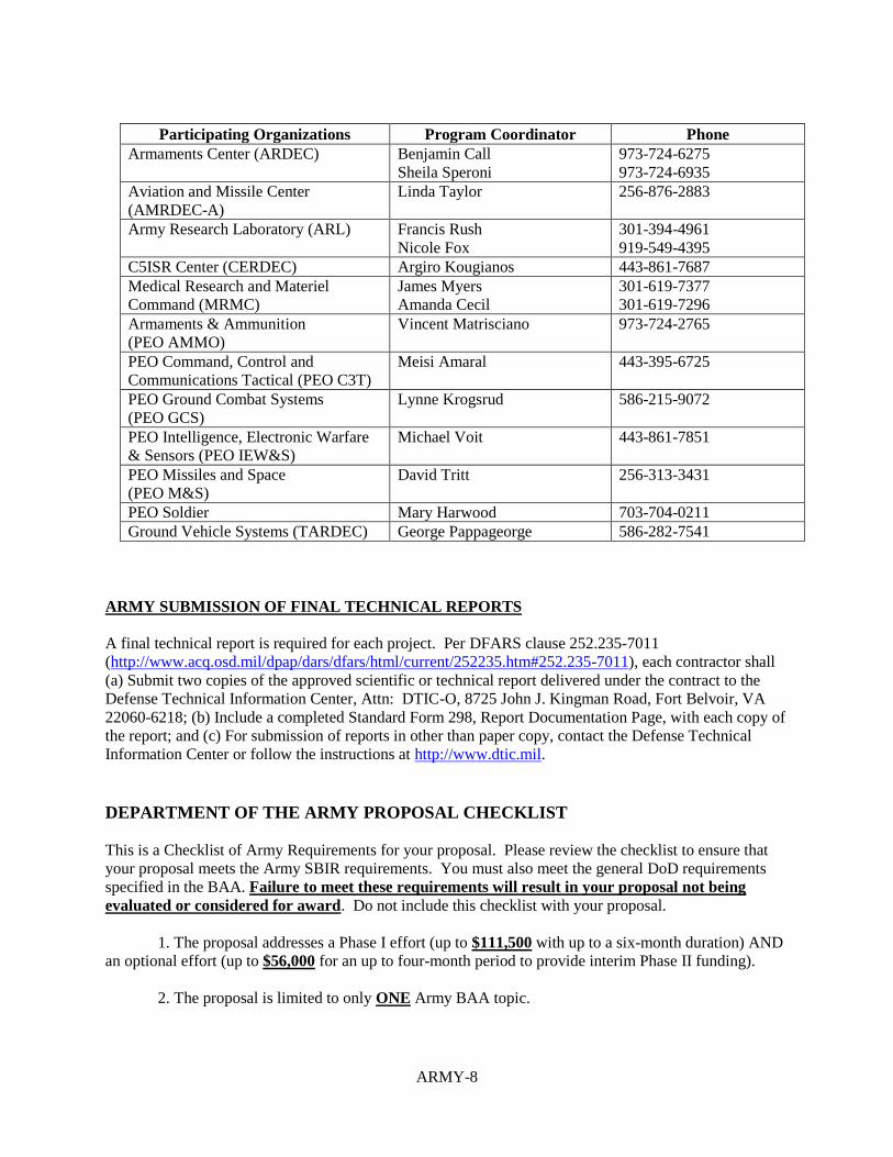
ARMY SBIR PROGRAM COORDINATORS (PCs) and Army SBIR 19.2 Topic Index
ARMY-8
Participating Organizations Program Coordinator Phone
Armaments Center (ARDEC) Benjamin Call
Sheila Speroni
973-724-6275
973-724-6935
Aviation and Missile Center
(AMRDEC-A)
Linda Taylor 256-876-2883
Army Research Laboratory (ARL) Francis Rush
Nicole Fox
301-394-4961
919-549-4395
C5ISR Center (CERDEC) Argiro Kougianos 443-861-7687
Medical Research and Materiel
Command (MRMC)
James Myers
Amanda Cecil
301-619-7377
301-619-7296
Armaments & Ammunition
(PEO AMMO)
Vincent Matrisciano 973-724-2765
PEO Command, Control and
Communications Tactical (PEO C3T)
Meisi Amaral 443-395-6725
PEO Ground Combat Systems
(PEO GCS)
Lynne Krogsrud 586-215-9072
PEO Intelligence, Electronic Warfare
& Sensors (PEO IEW&S)
Michael Voit 443-861-7851
PEO Missiles and Space
(PEO M&S)
David Tritt 256-313-3431
PEO Soldier Mary Harwood 703-704-0211
Ground Vehicle Systems (TARDEC) George Pappageorge 586-282-7541
ARMY SUBMISSION OF FINAL TECHNICAL REPORTS
A final technical report is required for each project. Per DFARS clause 252.235-7011
(http://www.acq.osd.mil/dpap/dars/dfars/html/current/252235.htm#252.235-7011), each contractor shall
(a) Submit two copies of the approved scientific or technical report delivered under the contract to the
Defense Technical Information Center, Attn: DTIC-O, 8725 John J. Kingman Road, Fort Belvoir, VA
22060-6218; (b) Include a completed Standard Form 298, Report Documentation Page, with each copy of
the report; and (c) For submission of reports in other than paper copy, contact the Defense Technical
Information Center or follow the instructions at http://www.dtic.mil.
DEPARTMENT OF THE ARMY PROPOSAL CHECKLIST
This is a Checklist of Army Requirements for your proposal. Please review the checklist to ensure that
your proposal meets the Army SBIR requirements. You must also meet the general DoD requirements
specified in the BAA. Failure to meet these requirements will result in your proposal not being
evaluated or considered for award. Do not include this checklist with your proposal.
1. The proposal addresses a Phase I effort (up to $111,500 with up to a six-month duration) AND
an optional effort (up to $56,000 for an up to four-month period to provide interim Phase II funding).
2. The proposal is limited to only ONE Army BAA topic.

ARMY-9
3. The technical content of the proposal, including the Option, includes the items identified in
Section 5.4 of the BAA.
4. SBIR Phase I Proposals have four (4) sections: Proposal Cover Sheet, Technical Volume, Cost
Volume and Company Commercialization Report. The Technical Volume .pdf document has a 20-page
limit including, but not limited to: table of contents, pages intentionally left blank, references, letters of
support, appendices, technical portions of subcontract documents [e.g., statements of work and resumes]
and all attachments). However, offerors are instructed to NOT leave blank pages, duplicate the
electronically generated cover pages or put information normally associated with the Technical Volume
in other sections of the proposal submission as THESE WILL COUNT AGAINST THE 20-PAGE
LIMIT. Any information that details work involved that should be in the technical volume but is inserted
into other sections of the proposal will count against the page count. ONLY the electronically generated
Cover Sheet, Cost Volume and Company Commercialization Report (CCR) are excluded from the
Technical Volume .pdf 20-page limit. As instructed in Section 5.4.e of the DoD Program BAA, the CCR
is generated by the submission website, based on information provided by you through the “Company
Commercialization Report” tool. Army Phase I proposals submitted with a Technical Volume .pdf
document of over 20-pages will be deemed NON-COMPLIANT and will not be evaluated.
5. The Cost Volume has been completed and submitted for both the Phase I and Phase I Option
and the costs are shown separately. The Army requires that small businesses complete the Cost Volume
form on the DoD Submission site, versus submitting within the body of the uploaded proposal. The total
cost should match the amount on the cover pages.
6. Requirement for Army Accounting for Contract Services, otherwise known as CMRA
reporting is included in the Cost Volume (offerors are instructed to include an estimate for the cost of
complying with CMRA).
7. If applicable, the Bio Hazard Material level has been identified in the Technical Volume.
8. If applicable, plan for research involving animal or human subjects, or requiring access to
government resources of any kind.
9. The Phase I Proposal describes the "vision" or "end-state" of the research and the most likely
strategy or path for transition of the SBIR project from research to an operational capability that satisfies
one or more Army operational or technical requirements in a new or existing system, larger research
program, or as a stand-alone product or service.
10. If applicable, Foreign Nationals are to be identified in the proposal.
ARMY-10
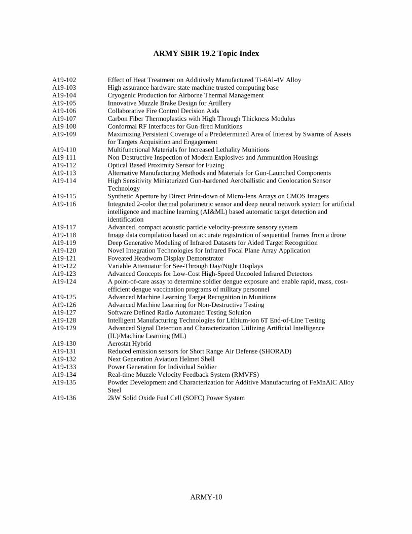
ARMY SBIR 19.2 Topic Index
A19-102 Effect of Heat Treatment on Additively Manufactured Ti-6Al-4V Alloy A19-103 High assurance hardware state machine trusted computing base A19-104 Cryogenic Production for Airborne Thermal Management A19-105 Innovative Muzzle Brake Design for Artillery A19-106 Collaborative Fire Control Decision Aids A19-107 Carbon Fiber Thermoplastics with High Through Thickness Modulus A19-108 Conformal RF Interfaces for Gun-fired Munitions A19-109 Maximizing Persistent Coverage of a Predetermined Area of Interest by Swarms of Assets
for Targets Acquisition and Engagement A19-110 Multifunctional Materials for Increased Lethality Munitions A19-111 Non-Destructive Inspection of Modern Explosives and Ammunition Housings A19-112 Optical Based Proximity Sensor for Fuzing A19-113 Alternative Manufacturing Methods and Materials for Gun-Launched Components A19-114 High Sensitivity Miniaturized Gun-hardened Aeroballistic and Geolocation Sensor
Technology A19-115 Synthetic Aperture by Direct Print-down of Micro-lens Arrays on CMOS Imagers A19-116 Integrated 2-color thermal polarimetric sensor and deep neural network system for artificial
intelligence and machine learning (AI&ML) based automatic target detection and
identification A19-117 Advanced, compact acoustic particle velocity-pressure sensory system A19-118 Image data compilation based on accurate registration of sequential frames from a drone A19-119 Deep Generative Modeling of Infrared Datasets for Aided Target Recognition A19-120 Novel Integration Technologies for Infrared Focal Plane Array Application A19-121 Foveated Headworn Display Demonstrator A19-122 Variable Attenuator for See-Through Day/Night Displays A19-123 Advanced Concepts for Low-Cost High-Speed Uncooled Infrared Detectors A19-124 A point-of-care assay to determine soldier dengue exposure and enable rapid, mass, cost-
efficient dengue vaccination programs of military personnel A19-125 Advanced Machine Learning Target Recognition in Munitions A19-126 Advanced Machine Learning for Non-Destructive Testing A19-127 Software Defined Radio Automated Testing Solution A19-128 Intelligent Manufacturing Technologies for Lithium-ion 6T End-of-Line Testing A19-129 Advanced Signal Detection and Characterization Utilizing Artificial Intelligence
(IL)/Machine Learning (ML) A19-130 Aerostat Hybrid A19-131 Reduced emission sensors for Short Range Air Defense (SHORAD) A19-132 Next Generation Aviation Helmet Shell A19-133 Power Generation for Individual Soldier A19-134 Real-time Muzzle Velocity Feedback System (RMVFS) A19-135 Powder Development and Characterization for Additive Manufacturing of FeMnAlC Alloy
Steel A19-136 2kW Solid Oxide Fuel Cell (SOFC) Power System
ARMY-11
ARMY SBIR 19.2 Topic Descriptions
A19-102 TITLE: Effect of Heat Treatment on Additively Manufactured Ti-6Al-4V Alloy TECHNOLOGY AREA(S): Air Platform
OBJECTIVE: The key objective of this work is to evaluate the mechanical properties and microstructural
characteristics of post-process heat treatments of Additively Manufactured (AM) Ti-6Al-4V alloy including process-
structure-property relationships. Tensile testing, smooth bar high cycle fatigue testing and microstructural analyses
are to be performed on Laser Powder Bed Fusion (L-PBF) manufactured near net shape Ti-6Al-4V specimens
having four heat treatment types after Hot Isostatic Pressing (HIP). These heat treatments are Mill-Anneal (MA),
ANNeal (ANN), Solution Treat and Age (STA) and Beta Solution Treat and Overaged (BSOA). The resulting
mechanical properties and microstructures will be compared to the traditional Ti-6Al-4V alloys bars, forgings and
castings. The quantitative process-structure-property relationships will be determined with computational modeling
with respect to build orientation.
DESCRIPTION: Additive Manufacturing (AM) is a new production technology that enables reduced manufacturing
steps, part consolidation and production of near net shape parts from 3-D model data. Current applications mainly
focus on secondary structures or other non-critical applications. Recent developments in AM technology and AM
Standards offer great potential to implement AM produced part in the US Army. In the past few decades, there is an
increasing interest to produce metallic AM parts for structural and non-structural applications, as these materials
show acceptable performances compared to the traditional materials with shorter lead times, less material usage and
near net-shape parts [1-8]. The use of AM titanium alloy replacement of a currently used traditional titanium alloy
in the US Army helicopters with a same traditional alloy heat treatment types may not provide an increased
utilization of the AM titanium alloy and may cause additional performance risk since heat treatment for AM
titanium alloy is not optimized.
The current standard ASTM F2924 [9] of the AM Ti-6Al-4V alloy mechanical properties in all direction requires
minimum tensile properties (130 ksi UTS/120 ksi YS/10% Elong) regardless of heat treatment types and part
thicknesses. The thickness of the part affects the grain size of the part during solidification as such the grain sizes
are smaller for the small thickness compared to the thick part. Therefore, tensile properties are higher for a part with
small grains even though both parts had same heat treatment types. On the other hand, the tensile properties are also
depends on heat treatment types. For example, annealing heat treatment provides lower tensile properties compared
to the solution heat and aged heat treatment. Therefore, the effects of heat treatment types coupled with part
thickness and resulting mechanical properties need to be thoroughly investigated.
In this study, the L-PBF AM process will be used to manufacture near net shape AM Ti-6Al-4V test specimens, and
evaluate the effect of post-processing heat treatment types on tensile and fatigue properties, compared to the baseline
Ti-6Al-4V alloy bar, forging and casting material properties. To understand the process-structure-property
relationships, computational modeling is to be utilized to predict the quantitative mechanical properties such as
tensile, yield, elongation and fatigue strength.
The project will be conducted in three phases. Phase I will focus on assessment, design and selection of parameters,
computational model, manufacturing options and procurement of AM Ti-6Al-4V alloy powder. Phase II will focus
on demonstrating the ability to manufacture near net-shape of tensile and fatigue specimens, perform tensile, fatigue
tests and evaluate tensile, fatigue test results of four heat treatment types (MA, ANN, STA and BSTOA) and
quantitative prediction of process-structure-property relationships along different directions. Ten tests (10) at room
temperature per heat treatment types will be evaluated for both tensile and high cycle fatigue (0.1 R-ratio) tests.
Beta transus temperature of the two specimens will be determined for heat treating guidance. The chemical
composition and density of each lot will be determined. The chemical composition and physical properties of the
Ti-6Al-4V powder will be verified. Only one batch of virgin powder and no recycled powder will be used. A few
trial manufacturing is to be made to verify specimen sizes, quality and tensile properties. Phase III will focus
introduction of AM Ti-6Al-4V alloy into a broad range of defense and civilian applications. This technology has
been demonstrated in a laboratory research scale and prototype parts. The current effort would use existing

ARMY-12
technology to develop an optimized heat treatment types for AM Ti-6Al-4V alloy process utilizing simple shaped
tensile and fatigue specimens. It is noted that the listed references [9-20] are to be used for general guidance on
materials, manufacturing, heat treatment, testing and reporting to accomplish the objective of this project. The
project’s three major phases are described below.
PHASE I: Phase One evaluates the engineering merit and feasibility of the proposed technology. It identifies and
builds team with industrial partners, design and select AM Ti-6Al-4V powder type, size and amount of experimental
test specimens, AM manufacturing and, assesses application and manufacturing options, addresses producibility and
inspectibility using these test specimens, selects predictive computer modeling and investigates the overall benefits
of the project. The interrelations among AM processed Ti-6Al-4V alloy heat treating conditions and resulting
microstructure parameters (alpha layer thickness, alpha and beta phase content, grain size, density, etc.) and
mechanical properties are still not fully understood. To understand the process-structure-property relationships
computational modeling need to be utilized to predict the quantitative mechanical properties. The objective of the
process-structure-property relationships between the heat-treating conditions and microstructural features is to be
able to predict the microstructure and resulting mechanical properties for a given part geometry, size, and feature
orientations for a given heat treating conditions. Such a model would be the basis for improving first part yield and
enabling rapid part qualification. In order to verify the process-structure-property relationships, experimentally
measured microstructural features and tensile properties are required in x, y and z directions. A generic
computational model or a modified one to predict properties could be used for predicting process-structure-property
relationships. To predict complex part process-structure-property relationships, selected complex shaped parts will
be modeled to determine properties. These representative complex shaped parts will be manufactured in Phase II
and mechanical properties and microstuctural features will be measured with respect specimen orientations for
modeling verification. Recommended computational modeling is to be demonstrated with open source
microstructure and mechanical data for the AM Ti-6Al-4V alloy. Further ideas beyond described are welcome. An
appropriate process modeling could be used to minimize process defects and maximize the mechanical properties for
optimum producibility if needed and funding are available.
Required Phase I deliverables include monthly progress reports, final technical report including specimen sizes,
testing specimens locations, tests, powder specification and amount, AM build layout and manufacturing plans,
predicted computational model examples demonstrating the process-structure-property relationships including
complex shapes.
PHASE II: Phase Two will manufacture the specimens and evaluate tensile and fatigue test results, predictive
computational modeling compared to the traditional Ti-6Al-4V alloy bars, forgings and castings. The process will
utilize an L-PBF process. The shapes of AM specimens will be simple-shaped L-PBF manufacturing. The overall
dimension in length could be 8.0 inches with three wall thickness ranges as 0.25, 0.50, 1.00 and 2.00 inches with
appropriate machining stocks. Any required radiuses could be 0.02 inches. All specimens will undergo HIP prior to
the following heat treatments: 1) mill-anneal, 2) anneal, 3) solution treated and age and finally 4) beta solution
treated and overaged. Tensile, fatigue, hardness, density, optical microscopy, scanning electron microscopy and
computer tomography (CT) analyses are to be utilized to generate and analyze the resulting data during the Phase II
effort. Ten (10) tests will be performed at room temperature per heat treatment types. Additionally, ten (10) tests
will be performed at room temperature as AM manufactured and as HIPed for baseline comparison. Tensile,
fatigue, hardness, density, optical microscopy, scanning electron microscopy and computer tomography (CT)
analyses are to be utilized to generate and analyze the resulting data during the Phase II tensile evaluation. The
specimens will undergo both tensile and high cycle fatigue (0.1 R-ratio) tests. Beta transus temperature of the two
specimens as well as the chemical composition of each lot will be determined for heat treating guidance.
Additionally, the chemical composition and physical properties of the Ti-6Al-4V powder will also be verified. Only
one batch of virgin powder (no recycled powder) will be used, and all specimens will come from the same AM build
feedstock. Trial printed specimens will be made to verify specimen sizes, quality and tensile properties. The
interrelations among AM processed Ti-6Al-4V alloy heat treating conditions and resulting microstructure
parameters (alpha layer thickness, alpha and beta phase content, grain size, density, etc.) and mechanical properties
are to be determined. To understand the process-structure-property relationships, computational modeling is to be
utilized to predict the quantitative mechanical properties. Such a model would be the basis for improving first part
yield and enabling rapid part qualification. In order to verify the model, experimentally measured microstructural
features and tensile properties are required in x, y and z directions. The resulting data is to be used to validate the
computational modeling.
ARMY-13
Required Phase II deliverables include bi-monthly progress reports, test reports, computational predictive
mechanical property evaluation and a final technical report including powder chemical and physical properties, AM
Ti-6Al-4V chemical analysis, CT and dimensional inspections, tensile, hardness, fatigue testing, microstructure,
fractography analysis, computational model inputs to predict properties, verification and example of the model
predictions.
PHASE III DUAL USE APPLICATIONS: Phase Three will address the transition path of this technology resulting
from Phase II effort to various US Army components with industrial partners and Original Equipment
Manufacturers (OEMs).
This technology has been demonstrated in a laboratory research scale and on prototype parts. This program effort
would use existing technology to develop an optimized heat treatment process for AM Ti-6Al-4V alloys,
quantitative process-structure-property relationships utilizing simple shaped tensile and fatigue specimens. It is
noted that the listed references [9-20] are to be used for general guidance on materials, manufacturing, and heat
treatment, testing and reporting to accomplish the objective of this project.
The implementation targets are defense applications. The expected benefit of the resulting project data could
become a heat treatment guide for AM Ti-6Al-4V alloy components used in US Army applications requiring tensile
strength, fatigue strength and combination of both tensile and fatigue strength for performance requirements. The
relevant technical data generated and experience gained in this project are expected to positively impact application
of additively manufactured titanium components in a broad range of defense applications where light weight and
reduced lead time are needed for very complex parts that use titanium components. All these project benefits will
result in improved U. S. readiness and capability.
REFERENCES: 1. Seifi, M.; Salem, A.; Beuth, J.; Harrysson, O.; Lewandowski, J.J. Overview of Materials Qualification Needs for
Metal Additive Manufacturing. JOM, 2016, 68, 747–764.
2. Song, B.; Dong, S.; Zhang, B.; Liao, H.; Coddet, C. Effects of processing parameters on microstructure and
mechanical property of selective laser melted Ti6Al4V. Mater. Des. 2012, 35, 120–125.
3. Kranz, J. Herzog, D. and Emmelmann, C., Design Guidelines for Laser Additive Manufacturing of Lightweight
Structures in Ti6Al4V, Journal of Laser Applications, 2015,Vol. 27, S1400-1-S14001-16.
4. Vilaro, T.; Colin, C.; Bartout, J.D. As-Fabricated and Heat-Treated Microstructures of the Ti-6Al-4V Alloy
Processed by Selective Laser Melting. Metall. Mater. Trans. A, 2011, 42, 3190–3199.
5. Kong, C.J.; Tuck, C.J.; Ashcroft, A.I.; Wildman, R.D.; Hague, R. High density Ti-6Al-4V via SLM processing:
Microstructure and mechanical properties. In Proceeding of the 22nd Annual International Solid Freeform
Fabrication Symposium, Austin, TX, USA, 8–10 August 2011, 475–483.
6. Quintana, O. A. Alvarez, J. McMillan, W. R. and Tomonto, C., Effects of Reusing Ti-6Al-4V Powder in a
Selective Laser Melting Additive System Operated in an Industrial Setting, JOM, 2018,Vol.70, No. 9 1863-1869.
7. Leuders, S.; Thöne, M.; Riemer, A.; Niendorf, T.; Tröster, T.; Richard, H.A.; Maier, H.J. On the mechanical
behaviour of titanium alloy TiAl6V4 manufactured by selective laser melting: Fatigue resistance and crack growth
performance. Int. J. Fatigue, 2013, 48, 300–307.
8. Cao, F., Zhang, T., Ryder, M. A., and Lados, D. A., A Review of the Fatigue Properties of Additively
Manufactured Ti-6AL-4V, JOM, 2018, Vol. 70, No. 3, 349-357.
ARMY-14
9. ASTM F2924-14, “Standard Specification for Additive Manufacturing Titanium-6 Aluminum-4 Vanadium with
Powder Bed Fusion,” ASTM International, West Conshohocken, PA, 19428.
10. AMS2801B, “Heat Treatment of Titanium and Titanium Alloy,” Issued 2003-03, Society of Automotive
Engineers, Warrendale, PA 15096.
11. ASTM F3049-14, “StandardGuide for Characterization Properties of Metal Powders for Additive Manufacturing
Processes,” ASTM International, West Conshohocken, PA, 19428.
12. AMS7003, “Laser Powder Bed Fusion Process,” Issued 2018-06, Society of Automotive Engineers, Warrendale,
PA 15096.
13. AMS7002, “Process Requirements for Production of Metal Powder Feedstock for Use in Additive
Manufacturing of Aerospace Parts,” Issued 2018-06, Society of Automotive Engineers, Warrendale, PA 15096.
14. ASTM F3301-18, “Standard for Additive Manufacturing – Post Processing Methods –Standard Specification for
Thermal Post-Processing Metal Parts Made Via Powder Bed Fusion,” ASTM International, West Conshohocken,
PA, 19428.
15. ASTM F3122, “Standard Guide for Evaluation Mechanical Properties of Metal Materials Made via Additive
Manufacturing Processes,” ASTM International, West Conshohocken, PA, 19428.
16. ASTM F2971, “Standard Practice for Reporting Data for Test Specimens Prepared by Additive Manufacturing,”
ASTM International, West Conshohocken, PA, 19428.
17. ASTM B311, “Standard Test Method for Density of Powder Metallurgy (PM) Materials Containing Less Than
Two Percent Porosity,” ASTM International, West Conshohocken, PA, 19428.
18. ASTM E1441, “Standard Guide for Computed Tomography (CT) Imaging,” ASTM International, West
Conshohocken, PA, 19428.
19. ASTM F3303, “Additive Manufacturing – Process Characteristics and Performance: Practice for Metal Powder
Bed Fusion Process to Meet Critical Applications,” ASTM International, West Conshohocken, PA, 19428.
20. AS1814, “Terminology for Titanium Microstructures.” Society of Automotive Engineers, Warrendale, PA
15096.
KEYWORDS: Additive manufacturing, heat treatment, Ti-6Al-4V alloy, tensile properties, microstructure, laser,
powder bed fusion, process structure property relationships
TPOC-1: Mr. Mustafa Guclu Phone: 256-313-8728 Email: [email protected]
TPOC-2: Katherine Olson Phone: 256-313-6642 Email: [email protected]
A19-103 TITLE: High assurance hardware state machine trusted computing base
ARMY-15
TECHNOLOGY AREA(S): Information Systems
OBJECTIVE: Cybersecurity systems need to take advantage of high assurance provided by state machines used for
aviation and safety critical systems. Offeror shall research a high assurance state machine trusted computing base
for a high assurance operating system.
DESCRIPTION: Safety critical systems use state machines to achieve high computer security assurance levels.
State machines make security reviews for EAL6 or higher tractable. Current generation aviation systems were not
developed with strong computer security requirements. Past cyber threats, [1]-[2], current cyber treats, Spectre [3]
and Meltdown [4], and future cyber treats need to be countered.
Embedded system designs are typically based on commodity hardware optimized exclusively for speed – leading to
critical cyber vulnerabilities that can have devastating effects on safety and mission effectiveness. This has also led
to the unsustainable “Perimeter, Patch, Pray” Information Assurance strategy [5] that is simply impractical for
fielded aviation and missile systems.
We are interested in researching a separation kernel-like operating system consisting of a hardware state machine as
the trusted computing base and a high assurance operating system. In terms of computer virtualization concepts:
the trusted computing base is a hardware state machine and the OS can be compared to a guest operating system.
Recent developments in the open source hardware and software communities have created the open source RISC-V
[6] and OpenPiton [7] microprocessors and high assurance open source operating system, seL4 [8]. Open source
architectures provide for more thorough security reviews compared to closed source systems [9]. Open source
architectures also provide for lower life cycle system cost. We are interested in leveraging the open source
communities for this research topic area. Preference will be given for open source hardware and operating system
modules.
PHASE I: For the Phase I proposal, offeror shall describe the feasibility of using a hardware and software co-design
to create a high assurance state machine as the trusted computing base for a high assurance operating system.
(1) Propose high assurance state machine trusted computing base concept.
(2) Propose an operating system to take advantage of trusted computing base.
(3) Propose a system architecture describing: hardware, microprocessor, state machine, operating system, and
application software.
(4) Describe the cybersecurity advantages of (3) over current commodity microprocessors and operating systems.
(5) A plan to achieve a cybersecurity security rating of at least EAL6.
(6) Describe potential Army, medical, and commercial applications; and
(7) Provide a business model to market the proposed system.
For the phase I effort, the offeror shall demonstrate the feasibility and security benefits of creating a high assurance
hardware state machine trusted computing base and high assurance OS.
(1) Develop models, simulations, prototypes, etc. to determine technical feasibility of developing a high assurance
system
(2) Deliver a System Architecture and Description Report; and
(3) Deliver an EAL Certification Plan Report.
PHASE II: Offeror shall develop a high assurance computer system based on offeror’s proposal and phase I effort.
It is highly recommended that the offeror team with a government prime contractor. The offeror shall demonstrate
high assurance computer system running an Army application (like Joint Multi-Role Technology Demonstrator
[19]). The Offer shall propose potential applications for a system demonstration and implement an application with
government concurrence.
Offeror shall deliver a year 1 report and a year 2 report describing artifacts, documents, verification tests, etc.
completed following the plan in the Phase I document EAL Certification Plan Report. Offeror shall deliver 2
prototype systems to the government point of contact for test and evaluation with all software tools and licenses (if

ARMY-16
required) to build and use the system. Offeror shall provide 2 days of on-site training for the system.
PHASE III DUAL USE APPLICATIONS: Offeror will develop and market high assurance system based on phase
II development work and marketing plan from phase I. Offeror will achieve EAL6 or greater for high assurance
computer system. Offeror will integrate high assurance hardware/OS system into an Army Aviation or Missile
subsystem currently under development or via technology refresh.
REFERENCES:
1. S. King, et al.: “SubVirt: implementing malware with virtual machines,” IEEE Symposium on Security
and Privacy, pp. 1-14, 21-24 May 2006.
2. R. Fannon: An analysis of hardware-assisted virtual machine based rootkits, Thesis, Naval Postgraduate
School, June 2014. calhoun.nps.edu/handle/10945/42621
3. P. Kocher, et al.: “Spectre Attacks: Exploiting Speculative Execution,” Cornell University Library, 3 Jan
2018. https://arxiv.org/pdf/1801.01203.pdf
4. M. Lipp, et al.: “Meltdown,” Cornell University Library, 3 Jan 2018. https://arxiv.org/pdf/1801.01207.pdf
5. Darpa: “Baking Hack Resistance Directly into Hardware,” 4/10/2017. https://www.darpa.mil/news-
events/2017-04-10.
6. A. Waterman, et. al. "The RISC-V Compressed Instruction Set Manual Version 1.9 (draft)" (PDF). RISC-
V. https://riscv.org/wp-content/uploads/2015/11/riscv-compressed-spec-v1.9.pdf
7. http://parallel.princeton.edu/openpiton/index.html#infosec.
8. G. Klein., et al.: "seL4: formal verification of an OS kernel,"Proceedings of the ACM SIGOPS 22nd
symposium on Operating systems principles, Big Sky, Montana, pp. 207-220, October 11 - 14, 2009.
9. R. Smith, "A Contemporary Look at Saltzer and Schroeder's 1975 Design Principles", IEEE Security &
Privacy, Vol. 10, No. 5, pp. 20-25, Nov.-Dec. 2012
10. P. Jungwirth, et al.: "Cyber defense through hardware security", Proc. SPIE 10652, Disruptive
Technologies in Information Sciences, 106520P (9 May 2018); doi: 10.1117/12.2302805;
https://doi.org/10.1117/12.2302805
11. T. Nakano: "Hardware Implementation of a Real-time Operating System," IEEE TRON Project
International Symposium, Tokyo, Japan, pp. 34-42, 28 Nov - 2 Dec 1995
12. https://www.renesas.com/en-us/products/factory-automation/multi-protocol-communication/r-in32m3-
hardware-rtos.html
13. M. McCoyd, et al.: "Building a Hypervisor on a Formally Verifiable Protection Layer,"
https://people.eecs.berkeley.edu/~mmccoyd/papers/minvisor-hicss-12.pdf
14. DARPA, "Clean-slate design of Resilient, Adaptive, Secure Hosts (CRASH)," DARPA-BAA-10-70, June
2010.
https://www.fbo.gov/index=opportunity&mode=form&id=4022d960a15e87bcaf0fb70101ab53b8&tab=core&
_cview=1
ARMY-17
15. J. Alves-Foss,et al.: A New Operating System for Security Tagged Architecture Hardware In Support of
Multiple Independent Levels of Security (MILS) Compliant Systems, University of Idaho, Center Secure and
Dependable Systems, Air Force Research Lab Tech Report AFRL-RI-RS-TR-2014-088, APRIL 2014.
16. J. Song, and J. Alves-Foss. "Security tagging for a zero-kernel operating system." System Sciences
(HICSS), 2013 46th Hawaii International Conference on. IEEE, 2013.
17. R. Shioya, et al.: "Low-Overhead Architecture for Security Tag," IEEE Pacific Rim International
Symposium on Dependable Computing, pp. 135-142, Shanghai, China, 16-18 Nov. 2009.
18. P.Jungwirth, et al.: "Hardware Security Kernel for Cyber Defense," SPIE Defense + Security Conference,
Baltimore, MD, April 2019.
19. http://www.defenseinnovationmarketplace.mil/resources/JMR_AMRDEC01.pdf
KEYWORDS: Assurance, cyber resilience, embedded systems, trusted computing, state machine
TPOC-1: Thomas Barnett Phone: 256-876-4361 Email: [email protected]
A19-104 TITLE: Cryogenic Production for Airborne Thermal Management TECHNOLOGY AREA(S): Air Platform
OBJECTIVE: Develop and demonstrate a practical lightweight system for an on wing cryogenic liquid production
system applicable to airborne thermal loads, and suitable for implementation on future US Army rotorcraft.
DESCRIPTION: Emerging aircraft concepts are calling for increased electrical power and in many cases all electric
aircraft designs. While accommodating the electric power requirement is a challenge in and of itself, thermal
management of the components for the system becomes a priority engineering challenge as well. Cooling
technology needs for these aircraft architectures are driven by the power and cooling demands of aircraft
components such as superconducting motors/generators, Directed Energy Weapons (DEWs), and high-powered
jammers. From a military perspective, high pulse power loads devices, such as DEWs, offer significant
opportunities, as well as challenges, compared to traditional kinetic weapons. Airborne DEWs could perform a
variety of Army missions including missile defense, counter-UAV operations, suppression of enemy air defenses,
precision strike, etc. Although not limited to high energy lasers (HELs), the challenge of integrating such a device
into a mission equipment package (MEP) illustrates the technical challenges ahead.
HELs do not consume ammunition in the traditional sense, though they do consume significant amounts of electrical
power. Lasers are intrinsically inefficient, and the “wall plug” efficiency can be considerably less than 50%. This
means that to fire a 50 kW laser, 100 kW of electrical power would be needed. In addition, the net 50 kW of waste
heat that is rejected to fire the laser must also be cooled which requires a cooling device that adds more size, weight,
and power (SWaP). Typically the laser itself has tight thermal constraints which limit temperature changes to +/- 1°
Celsius. Additionally, operating temperatures of the device are close to the operating temperatures of the external
ambient air. The low-quality heat is extremely difficult to move around. Therefore, significant incentive exists to
maximize the efficiency of airborne DEWs to minimize both power and thermal management requirements.
One way to enhance the efficiency of a laser is to cool it and operate the laser at cryogenic temperatures. Research
has shown that wall-plug efficiency in excess of 70% is possible for cryogenically cooled solid-state lasers using

ARMY-18
liquid nitrogen (LN2). An airborne DEW operating at this efficiency would have significantly reduced power and
thermal management requirements, but these benefits are only possible if the system is cryogenically cooled. For a
cryogenic cooling system to be attractive, the benefits of increased efficiency must outweigh the cost, complexity
and SWaP penalties associated with its implementation. If successfully developed, a low weight cryogenic liquid
generator could be applied to a cooling system for superconducting motor/generators, high powered jammers, and/or
HEL type devices.
Metric goals and characteristics for the on-wing cryogenic liquid generator are as follows. The ratio of the amount of
liquid cryogen produced per day to the device weight ((liters/day)/kg) should be greater than 1; with higher ratios
being consequentially more desirable. For close looped systems assume the system has already been chilled and/or
the reservoir is available. Production (cooling capability) goal is greater than or equal to 100 liters/day. Weight of
the production equipment should not exceed 250 kg; weight is highly valued on a rotorcraft, hence any that can be
removed should be. Operational ceiling is up to 5500 meters; performance must be characterized over the
operational range. Temperatures up to 50 Celsius should be considered. If bleed air from an aircraft engine or
secondary power unit (SPU) is required in the design, limit the bleed flow to a maximum .45 kg/sec (1 lb. /sec).
Electrical power to drive equipment can assume 270VDC and an allotment of up to 40 kW of electrical load. Note,
this system is not limited to LN2, innovative concepts which use any low temp fluid will be considered, such as, but
not limited to liquefied natural gas (LNG), Ammonia, liquid ethylene, etc.
PHASE I: Develop a design for a cryogenic liquid generator which meets or exceeds the aforementioned
specifications. Utilization of models, and a systems engineering perspective is encouraged.
PHASE II: Develop and demonstrate the critical components of the cryogenic liquid generator through prototyping
and laboratory component/system testing.
PHASE III DUAL USE APPLICATIONS: Phase III options would include development of a fully-functional
prototype that could be used for cryogenic DEW ground and flight testing. For dual us applications the same
technology could also be applied for other ground, naval, and airborne thermal management applications such as
cooling superconducting systems including high-efficiency, compact motors and generators and lightweight power
distribution systems.
REFERENCES: 1. J. P. Perin, et al., “Cryogenic Cooling For High Power Laser Amplifiers”, IFSA 2011 - Seventh International
Conference on Inertial Fusion Sciences and Applications, Bordeaux, France.
2. R. Paschotta, article on 'cryogenic lasers' in the Encyclopedia of Laser Physics and Technology, 1. Edition
October 2008, Wiley-VCH, ISBN 978-3-527-40828-3
3. Rodger W. Dyson, “Novel Thermal Energy Conversion Technologies for Advanced Electric Air Vehicles”
4. Scheidler, Justin J. PhD., “Preliminary Design of the Superconducting Rotor for NASA’s High-Efficiency
Megawatt Motor. AIAA Propulsion and Energy Forum. July 9-11, 2018.
5. “U.S. Army Weapons-Related Directed Energy (DE) Programs: Background and Potential Issues for Congress”,
Congressional research Service Report R45098 (2018).
6. Vretenar, N., et al., “Cryogenic Yb:YAG Thin Disk Laser”, AFRL Technical Paper AFRL-RD-PS-TP-2016-0004
(2016).
KEYWORDS: Directed energy weapons, auxiliary power unit, thermal management, cryogenic cooling
TPOC-1: John Hailer Phone: 757-878-5003 Email: [email protected]
ARMY-19
TPOC-2: Eli Thorpe Phone: 757-878-2400 Email: [email protected]
A19-105 TITLE: Innovative Muzzle Brake Design for Artillery TECHNOLOGY AREA(S): Weapons
OBJECTIVE: Develop novel muzzle brake structures for extended range cannon artillery systems that reduce mass
and manufacturing cost, while maintaining or improving recoil reduction, signature management, durability, and
operator safety.
DESCRIPTION: Given the Army’s Long-Range Precision Fires priority, a need exists for novel and innovative
muzzle brakes capable of supporting the new extended range cannons. These include but are not limited by
munitions currently under development for direct and indirect fire missions. High pressure produced at muzzle exit
have negative impact upon the surrounding environment due to muzzle blast flow fields exiting the barrel. The
negative consequences, such as recoil and noise production, can be alleviated by redirecting propellant gases.
Muzzle brakes have been used for decades to efficiently redirect propellant gas, resulting in effective performance
gains. However, recent advances in materials and additive manufacturing techniques show promise for muzzle brake
weight reduction and manufacturing cost while maintaining the favorable flow field response and resistance to the
resulting thermal and pressure loading.
Muzzle brakes are subject to complex loading due to high exit pressure and gas momentum from the projectile
emersion from the gun tube. Conditions at muzzle exit are dynamic and vary based on multiple factors. Typical
pressure and thermal conditions have been found to be as much as 10-12 ksi and 2000 K, respectively. Gas flow has
been found to be as high as 1,500 m/s and may contains small particles, such as solid propellant grains that did not
undergo combustion. The muzzle environment can cause erosion on the brake surfaces. The shape of the muzzle
brakes often consists of complex three-dimensional curves and multiple openings. Examples of various muzzle
brakes over the last century can be found in the references. Due to the harsh environment, material performance
requirements, and complex shapes muzzle brakes used in current artillery systems are made of cast/forged steel.
This topic seeks to develop novel applications of advanced materials, coatings and manufacturing technologies to
muzzle brakes. A variety of analyses and tests should be done to show that the materials can survive the
environment and that the manufacturing process can produce the complex shapes required. The objective for this
effort is to achieve 30 percent weight reduction with either comparable or reduced cost compared to conventional
steel muzzle brakes.
PHASE I: Evaluate various material and coating combinations for use in the muzzle brake environment. Investigate
manufacturing technologies such as additive manufacturing for combination with promising materials and coatings.
Reference 1 (AMCP 706-251), section 3-3.2 provides an example of an open muzzle brake that can be used as a
baseline. Conduct an analysis of alternatives to select the best combination of materials and manufacturing for
prototypes to be delivered in Phase II. Select a candidate shape for Phase II. Reference 4 (US Patent No 8,424,440)
for a 105mm gun is the preferred shape but other 105mm or 155mm shapes may be used with TPOC concurrence.
Perform a preliminary validation of the manufacturing concept and prepare initial production cost estimates for the
designs under consideration.
PHASE II: Subject promising material / coating combinations identified in Phase I to tests that simulate live fire
conditions. Perform feasibility trials on the production of the muzzle brake design selected in Phase I. Produce at
least one prototype muzzle brake using the selected final material / coating / manufacturing combination. Subject “as
manufactured” sections of the prototype to simulated firing conditions to assess as manufactured performance.
ARMY-20
Perform final design refinements. Document final material, coating, and manufacturing process.
PHASE III DUAL USE APPLICATIONS: Conduct a live fire demonstration of the final prototype in an operational
environment with involvement from the prime contractor for the weapon system. Explore potential small arms
applications for both military and private sector customers.
REFERENCES: 1. Headquarters, U. S. "Army Materiel Command," Engineering Design Handbook: Guns Series; Muzzle Devices"
AMC Pamphlet, Document No." (1968): 706-251. (https://apps.dtic.mil/dtic/tr/fulltext/u2/838748.pdf)
2. Carlucci, Donald E., and Sidney S. Jacobson. Ballistics: Theory and Design and Ammunition. CRC Press, 2018.
3. Schlenker, George. Contribution to the Analysis of Muzzle Brake Design. ROCK ISLAND ARSENAL IL, 1962.
(https://apps.dtic.mil/dtic/tr/fulltext/u2/276154.pdf)
4. Carson, Robert, and Christopher Aiello. "Low blast overpressure muzzle brake." U.S. Patent No. 8,424,440. 23
Apr. 2013.
5. Smith, Morris Ford. "Gun." U.S. Patent No. 817,134. 3 Apr. 1906.
6. Scheider, Eugene. “Prance.” U.S. Patent No. 1,363,058. 21 Dec 1920.
7. August, Bauer. "Silencer and recoil reducer for firearms." U.S. Patent No. 2,457,802. 4 Jan. 1949.
8. Emilien, Prache Jacques. "Muzzle recoil check for firearms." U.S. Patent No. 2,567,826. 11 Sep. 1951.
9. Thierry, R. "Muzzle attachment for reducing the recoil and blast effect of guns." U.S. Patent No. 3,714,864. 6
Feb. 1973.
10. Ledys, Francis, and Jacques Bachelier. "Muzzle brake for weapon barrel." U.S. Patent No. 6,216,578. 17 Apr.
2001.
11. Franchino, Anthony R., and Thomas Tighe. "Radial-venting baffled muzzle brake." U.S. Patent No. 6,578,462.
17 Jun. 2003.
12. Bounds, Roger. "Lateral projection muzzle brake." U.S. Patent No. 7,032,339. 25 Apr. 2006.
13. Poff, Charles. "Firearm muzzle brake." U.S. Patent No. 7,530,299. 12 May 2009.
KEYWORDS: muzzle device, muzzle brake, manufacturing, artillery, cannon
TPOC-1: Andrew Littlefield Phone: 518-266-3972 Email: [email protected]
A19-106 TITLE: Collaborative Fire Control Decision Aids TECHNOLOGY AREA(S): Weapons

ARMY-21
OBJECTIVE: Develop a system to aggregate friendly force small arms fire control data to compute and display
which individual or team has the highest probability of successfully engaging a target.
DESCRIPTION: This effort supports the Army Modernization Priority of Soldier Lethality.
Smart, networked small arms fire control systems are increasingly commonplace, especially with the proliferation of
smartphones. Devices like the Kestrel Weathermeter [1] and the Sig Sauer KILO2400ABS laser rangefinder [2]
have the capability to communicate with devices like smartphones to share data on environmental conditions, the
weapon itself, and ammunition. These capabilities allow users to quickly create and edit ballistic inputs to maximize
effects.
In addition, there are techniques [3] that have been developed to compute the probability of hit for a small arms
weapon system based upon the uncertainty in parameters like range to target, muzzle velocity, and wind speed.
These techniques allow a user to provide a performance estimate for a weapon system given its ballistic parameters
and the user's ability to measure and control the other factors that affect the flight of a bullet.
By developing a method to connect the fire control systems to a centralized probability of hit calculator, this topic
seeks to provide unit commanders with the capability to determine which asset at his disposal (e.g. infantry with an
M4 or a sniper with an M110 and a laser rangefinder) would best be able to engage a given target. This would not be
based only on user-provided information but would tie in actual measurements from sensors like weather meters,
laser rangefinders, and weapon-mounted displays. Target/enemy information, such as enemy position and threat
type, could be provided to the calculator from any number of sources, e.g., radar or individual user input. This data
will provide the most accurate picture of friendly units' ability to engage threats. The integration of this data would
enable a commander to evaluate the impact of moving units and threats around on a map, and to evaluate how the
firing solutions and P(hit) calculations change, allowing him to determine which unit should engage each target to
maximize the probability of successfully neutralizing the enemy.
PHASE I: The objective of Phase I is to develop a system architecture and methodology for aggregating fire control
data over a generic network that enables the data to be transferred and shared among systems. Document the
proposed solution. Demonstrate software that couples simulated data from multiple sources with target profiles to
compute a firing solution and probability of hit for each friendly asset.
PHASE II: Phase II will build on a successful Phase I demonstration to connect physical devices to the probability
of hit application and develop a user interface that presents the information on a map. The map should factor local
terrain into the firing solution. The application should allow the input of enemy locations from users or from other
sources. Demonstrate the capability to concurrently connect over 50 devices to the network and display their
computed performance probabilities based upon the entered enemy parameters.
PHASE III DUAL USE APPLICATIONS: This technology can be provided to law enforcement to help in
deployment of their units in counter-sniper applications. This capability could be extended to other types of
munitions, such as vehicle mounted weapons or indirect fire weapons, to help commanders better plan positioning of
the units. There is also the potential for this capability to be used in the commercial market, allowing hunters to
determine the best place to set up for engaging targets.
REFERENCES: 1. H. Chen, "Research on multi-sensor data fusion technology based on PSO-RBF neural network," 2015 IEEE
Advanced Information Technology, Electronic and Automation Control Conference (IAEAC), Chongqing, 2015, pp.
265-269. doi: 10.1109/IAEAC.2015.7428560
2. http://www.nkhome.com/support/kestrel-support/kestrel-software-and-apps/kestrel-link-ballistics-for-android/
3. https://www.sigsauer.com/store/kilo2400abs.html
ARMY-22
4. http://www.appliedballisticsllc.com/Articles/ABDOC115_ProbabalisticWEZ.pdf
5.
https://www.google.com/url?sa=t&rct=j&q=&esrc=s&source=web&cd=2&cad=rja&uact=8&ved=2ahUKEwj2rIK
W29beAhURu1MKHebEBdgQFjABegQIBRAB&url=https%3A%2F%2Fieeexplore.ieee.org%2Fiel7%2F7422354
%2F7428505%2F07428560.pdf&usg=AOvVaw0vHHR2xHluj7W8I7NB-y_F
KEYWORDS: Small arms, fire control, networked, probability of hit, sniper
TPOC-1: Ramon Llanos Phone: 973-724-5866 Email: [email protected]
TPOC-2: Shaji Kaniyantethu Phone: 973-724-7713 Email: [email protected]
A19-107 TITLE: Carbon Fiber Thermoplastics with High Through Thickness Modulus TECHNOLOGY AREA(S): Weapons
OBJECTIVE: Increase the through thickness modulus of carbon fiber thermoplastic composites through the use of
nano-additives. These composites are used on large caliber direct and indirect fire gun tubes. They use
polyetheretherketone (PEEK) as the thermoplastic matrix and are processed via fiber placement. The increase in the
through thickness modulus should not decrease the in-plane properties of the composite nor the ability to process it
via fiber placement.
DESCRIPTION: There is a need to increase the through thickness modulus in fiber placed thermoplastic
composites. These materials are being used to overwrap gun tubes for both direct and indirect fire and the
effectiveness of the composite wrap is limited by the through thickness modulus. Traditionally this modulus is only
that of the matrix material which is an order of magnitude or more lower than that of the reinforcement. On
previous efforts it was found that after about 0.5 - 0.75 inches of overwrap adding additional material doesn't help
with limiting bore dilation due to the low modulus in the radial direction being solely a function of the matrix. This
effort focuses on developing a process to increase the through thickness modulus by adding nano-materials to the
matrix. The addition of these materials should not be detrimental to the in-plane properties of the base composite
and should still be processable via fiber placement.
PHASE I: Develop a process to increase the through thickness modulus of carbon fiber reinforced thermoplastic by
adding nano-materials to the system. For this effort the baseline material is the fully unidirectional carbon fiber /
polyetheretherketone (PEEK) system commonly referred to as IM7/PEEK. This material is processed via fiber
placement using either hot gas torches or lasers as the heating source. The material is processed as a fully
consolidated tape of IM7/PEEK. A study should be conducted as to what type / loading amount of nano-material
will give the highest increase in through thickness modulus without degrading in plane properties or processability.
A suggested method for measuring the through thickness modulus is ASTM D695 with two to one size anisotropy
though other methods are acceptable. The threshold is a 75% increase in through thickness modulus over the
baseline of pure PEEK. The objective is a 200% increase. The material deliverable is the equivalent of one square
meter (can be of any width) of the improved material for testing. The material deliverable does not have to be in a
form processable by fiber placement but should be processable by heated platen press or autoclave.
PHASE II: Refine the process and improve the modulus results over Phase I. Minimum expected improvement is
100% over pure PEEK with an objective of 200% or more increase. Material must be processable via fiber
placement. The as processed interlaminar shear strength (D2344 -Standard Test Method for Short-Beam Strength of
ARMY-23
Polymer Matrix Composite Materials and Their Laminates), shall be equal to or greater than 9 ksi and any deviation
from this value shall be reported and a plan to achieve 9 ksi shall be described. No degradation of the in-plane
properties shall be verified by conducting at a minimum ASTM D3039 (Standard Test Method for Tensile
Properties of Polymer Matrix Composite Materials) in both longitudinal and transverse directions. Thermal
conductivity shall also be measured to determine if there is any increase over the baseline material. The material
deliverable is 25 lbs of 1/2" wide material capable of being processed via fiber placement.
PHASE III DUAL USE APPLICATIONS: Finalize the development of a material-based solution at production level
quantities that can be readily implemented on existing manufacturing equipment. Non-DoD applications include
down well piping, engine components, etc.
REFERENCES: 1. J. B. Root and A. G. Littlefield, Minimizing Rail Deflections in an EM Railgun, November 2006.
http://handle.dtic.mil/100.2/ADA481582
2. R. M. Erb, R. Libanori, N. Rothfuchs, A. R. Studart, "Composites Reinforced in Three Dimensions by Using Low
Magnetic Fields," Science, Vol 335, 13 Jan 2012, pp 199-204
3. L. Burton, R. Carter, V. Champagne, R. Emerson, M.l Audino, and E. Troiano, Army Targets Age Old Problems
with New Gun Barrel Materials, AMPTIAC Quarterly, v8n4, 2004.
http://ammtiac.alionscience.com/pdf/AMPQ8_4ART08.pdf
4. A. Littlefield and E. Hyland, Prestressed Carbon Fiber Composite Overwrapped Gun Tube, November 2006.
http://handle.dtic.mil/100.2/ADA481065
5. S. Montgomery and R. L. Ellis, Large Caliber Gun Tube Materials Systems Design, 10th U.S. Army Gun
Dynamics Symposium Proceedings, Austin, TX, April 2002. http://handle.dtic.mil/100.2/ADP012479
6. U.S. Army Materiel Command, "Research and Development of Materiel, Engineering Design Handbook, Gun
Series, Gun Tubes," AMCP 706-252, Washington DC (1964). http://handle.dtic.mil/100.2/AD830297
7. Office of the Secretary of Defense (OSD) Manufacturing Technology Program, Manufacturing Readiness Level
(MRL) Deskbook, Version 2.0, May 2011. http://www.dodmrl.com/MRL_Deskbook_V2.pdf
8. J. B. Root, V. Olmstead, A. G. Littlefield, K. Truszkowska, "An Analysis of EM Railgun Cross Section Designs,"
ARDEC Technical Report ARWSB-TR-09017, Aug 2009, http://www.dtic.mil/docs/citations/ADA593788
9. W. Zhang, J. Suhr, N. Koratkar, "Observation of High Buckling Stability in Carbon Nanotube Composites",
Advanced Materials, Vol 18, 4, 2006, 452-456.
10. M.A. Rafiee, J. Rafiee, Z. Wang, H. Song, Z.Z. Yu, N. Koratkar, "Enhanced Mechanical Properties of
Nanocomposites at Low Graphene Content", ACS Nano, 3 (12), 2009, 2884-3890
11. M.A. Rafiee, J. Rafiee, Z. Wang, H. Song, Z.Z. Yu, N. Koratkar, "Enhanced Mechanical Properties of
Nanocomposites at Low Graphene Content", ACS Nano, 3 (12), 2009, 2884-3890
KEYWORDS: Advanced Composites, Nanomaterials, fiber placement, thermoplastic composites
TPOC-1: Andrew Littlefield Phone: 518-266-3972 Email: [email protected]
ARMY-24
A19-108 TITLE: Conformal RF Interfaces for Gun-fired Munitions
TECHNOLOGY AREA(S): Electronics
OBJECTIVE: Investigate and develop innovative solutions to enable integration of electronic warfare antennas on
munition launched rounds. Antenna systems must be capable of surviving a typical mortar gun launch and
maintaining their operational performance throughout flight.
DESCRIPTION: Recent advancements in high-shock, munition-launched compatible electronics technology
particularly have opened up a wide realm of possibilities for enabling long-range and inexpensive electronic warfare
attacks of ground targets via relatively inexpensive munition launched systems and projectiles. To enable this
mission, projectiles must be equipped the associated electronics and RF sensors. Due to the highly constrained
volume and structural integrity requirements, these sensors must be conformal to the outer mold line with very
minimal intrusion into the structural wall of the projectile. Surface area on these projectiles is also very limited;
therefore, these sensors must be small, residing within the allotted payload space. It is also requisite that the sensor
operates over several ISM bands, while providing omni-directional beam pattern coverage. All this must be
performed at shock loads approaching 20,000 g’s.
Army is looking for novel advancements in conformal antenna technology to enable this mission set on a range of
prospective gun-launched platforms (e.g. mortars and artillery). Aperture designs should be innately scalable to
accommodate different munitions with tuneable frequency characteristics and incorporate knowledge and
understanding of relevant high-shock compatible materials and construction techniques. A critical aspect of the
effort involves that the apertures are insensitive to large changes in response due to the large shock loads
experienced during launch. Furthermore, designs should incorporate knowledge and understanding of
miniaturization techniques, while still achieving the objective bandwidth and pattern coverage requirements.
PHASE I: During the Phase I contract, successful proposers shall conduct a proof of concept study that focuses on
the feasibility of designing the antenna apertures. Investigations should include analysis of potential aperture
mounting configurations, achievable antenna performance (gain, bandwidth, pattern coverage), and materials
capable of surviving the expected environments. Verification of RF performance shall be accomplished through
simulation and prototype antenna measurements. A final proposed concept design, including a detailed description
and analysis of both expected thermal and mechanical loads, is expected at the completion of the Phase I effort.
PHASE II: If selected for a Phase II, the proposer shall fabricate and integrate the prototype antenna apertures into a
nominal projectile form-factor. The proposer shall further their proof of concept design by performing component
shock and thermal testing on critical components/connections of the aperture. Special emphasis on launch
survivability will be required, including hard force and electromagnetic effects during testing to ensure the apertures
can avoid failure or degradation. Upon evaluation of the design through a critical design review, the prototype
hardware’s survivability shall be demonstrated through either air-, chemical-, or munition launches. Information and
data collected from the flights will be used to validate operational electrical performance.
PHASE III DUAL USE APPLICATIONS: Phase III selections shall ruggedized final design, fabricate it and
integrate the prototype antenna apertures into nominal projectile form-factor to be identified by the Government.
Live fire tests will be conducted and the antenna integrated with projectile form-factor will have to withstand shock
load approaching 20,000g’s. Phase III selections might have adequate support from an Army prime or industry
transition partner identified during earlier phases of the program. The proposer shall work with this partner (TBD) to
fully develop, integrate, and test the performance and survivability characteristics of the design for integration onto
the vendor’s target platform.
COMMERCIALIZATION: Robust, high-shock antenna components are continually in demand by the aerospace
and chemical / petroleum industry. Further commercial applications include civilian space-flight initiatives and
application of the antenna technology for the design of low-cost, high-temperature, high-shock antenna sensors.
REFERENCES:
ARMY-25
1. Grzybowski, David M., Philip J. Peregino, and Bradford S. Davis. Development of a Telemetry-Enabled High-G
Projectile Carrier. No. ARL-TR-6099. ARMY RESEARCH LAB ABERDEEN PROVING GROUND MD
WEAPONS AND MATERIALS RESEARCH DIRECTORATE, 2012.
http://www.dtic.mil/dtic/tr/fulltext/u2/a568926.pdf
2. US Army Test and Evaluation Command Operations Procedure, "Projectile Velocity Measurements" (Top 4-2-
805) http://www.dtic.mil/dtic/tr/fulltext/u2/a119554.pdf
3. M120 Mortar System, https://en.wikipedia.org/wiki/Soltam_K6
4. http://en.wikipedia.org/wiki/Mortar_(weapon).
5. https://en.wikipedia.org/wiki/M777_howitzer
KEYWORDS: Antenna, electronic warfare, projectile, munition, mortar, artillery, sensors
TPOC-1: Ramon Llanos Phone: 973-724-5866 Email: [email protected]
TPOC-2: Wesley Wang Phone: 973-724-7869 Email: [email protected]
A19-109 TITLE: Maximizing Persistent Coverage of a Predetermined Area of Interest by Swarms of
Assets for Targets Acquisition and Engagement TECHNOLOGY AREA(S): Air Platform
OBJECTIVE: Design and develop an optimization algorithm to provide persistent coverage of an area of interest by
swarms of assets for target acquisition and engagement.
DESCRIPTION: This effort aims to provide a significant capability to the Soldier Lethality CFT by increasing data
accuracy during the direct fire engagement process for digital soldiers. This topic will also develop swarming
technologies that can be integrated into NGCV for targeting and engagement; specifically by utilizing augmentation
of LOS/BLOS NGCV fires and effects integrated with upper-echelon systems for cooperative engagement, as well
as the integration of fires and maneuver to achieve tactical overmatch. Current technologies should allow the
development an optimized solution to cover a predetermined area of interest by the swarms of combined assets in
the persistent way. In particular, this coverage will involve both mobile and stationary target acquisition and
engagement assets. Some of these assets may be weaponized to engage the targets. The route patterns of moving
assets can be assumed to be fixed in order to satisfy the persistent surveillance requirement. Also, periodic
maintenance and refueling/recharging must be addressed. For stationary assets, the maintenance requirements may
be significantly relaxed since the power consumption of these assets can be significantly reduced. The algorithm
must also account for the possibility that assets may have the capability to fly and perch on the wall of the building,
inside a cave or tunnel, on the trunk of a tree, or on other structures depending on the asset’s size, weight, and other
factors. These assets might geolocate the targets and serve as potential forward observers for engaging the targets.
The optimized solution should rely as much as possible on autonomy to enable assets capable to return to their
place(s) of origin on with minimal communication both among assets with the operator unit controller (OUC).
Special attention should also be paid to assure the collision avoidance among assets.
PHASE I: Design and develop innovative state-of-the-art software optimization algorithm for the persistent
coverage of a predetermined area of interest by the swarms of assets capable of autonomous navigation. Model the

ARMY-26
algorithm’s performance with data supply by assets with “fly and perch” capability. Demonstrate how the proposed
algorithms will optimize the coverage provided by assets in a dynamic threat environment.
PHASE II: Develop and demonstrate a prototype capability with swarms of at least six assets autonomously
navigating over a predetermined area of interest using the developmental offline software algorithms. The
collaborative assets should demonstrate the capability of autonomous return to their points of origin. The prototype
should demonstrate assets’ ability to transition to the forward observer state from the perching and dormant states
based on the appropriate input triggers to initiate collaborative target engagement. This prototype should be capable
of integrating with CCDC Armaments Center supplied fires and effects architecture. Conduct testing to demonstrate
feasibility of this technology for operation within a simulation environment operated by CCDC Armaments Center.
PHASE III DUAL USE APPLICATIONS: CCDC Armaments Center swarming/perching technology developed
under this effort should have open architecture allowing it to be easily integrated with the tactical decision support
systems and to enable swarming munition technologies. Department of Homeland security could use this capability
to monitor the illegal crossings of the US borders. In addition, SOCOM could use this technology for surveillance of
terrorist activities in urban places, while FBI/CIA could use it for intelligence gathering.
REFERENCES: 1. Z.R. Bogdanowicz, “Swarm of autonomous unmanned aerial vehicles with 3D deconfliction”, Proc. SPIE 10651,
Open Architecture/Open Business Model Net-Centric Systems and Defense Transformation 1018, 106510L (9 May
2018), SPIE Defense + Security, 2018, Orlando, Florida. .
2. Z.R. Bogdanowicz, “Flying swarm of drones over circulant digraph”, IEEE Transactions on Aerospace and
Electronic Systems, Vol. 53, No. 6, 2662—2670, 2017.
3. Y. Cao, W. Yu, W. Ren, and G. Chen, “An overview of recent progress in the study of distributed multiagent
coordination”, IEEE Transactions on Industrial Informatics, Vol. 9, no. 1, 427—438, 2013.
4. Z. Chen, M. C. Fan, and H. T. Zhang, “How much control is enough for network connectivity preservation and
collision avoidance?”, IEEE Transactions on Cybernetics, Vol. 45, No. 8, 1647—1656, 2015.
5. B. Fidam, V. Gazi, S. Zhai, N. Cen, and E. Karatas, “Single-view distance-estimation-based formation control of
robotic swarms”, IEEE Transactions on Industrial Electronics, Vol. 60, No. 12, 5781—5791, 2013.
6. J. H. Son and H. S. Ahn, “Formation coordination for propagation of group of mobile agents via self-mobile
localization”, IEEE Systems Journal, Vol. 9, No. 4, 1285—1296, 2015.
KEYWORDS: Perching, autonomous UAV/UGV, swarm of UAVs/UGVs, forward observer, target engagement,
weaponized UAVs/UGVs.
TPOC-1: Zbigniew Bogdanowicz Phone: 973-724-8034 Email: [email protected]
TPOC-2: Ketula Patel Phone: 973-724-8671 Email: [email protected]
A19-110 TITLE: Multifunctional Materials for Increased Lethality Munitions
ARMY-27
TECHNOLOGY AREA(S): Weapons
OBJECTIVE: Develop novel multifunctional materials for the next-generation munitions for the long-range
precision fire (LRPF) program under the Army Modernization effort to provide increased lethality and impose
superiority on contested and expanded battlefield.
DESCRIPTION: With the evolution of modern battlefields, the Army is seeking a new generation of munitions to
overmatch, deter and disrupt its adversaries. The next-generation of weapons aims to provide an increased kinetic
advantage over increasingly complex targets, situations and at longer distances. The development and
implementation of such systems will require new multifunctional materials and components with advanced effects to
maintain and further extend our troops’ superiority. The increased complexity of munitions, where target
identification and guidance systems now occupy a larger portion of the warhead, has been made at the expense of
the payload. The integration of reactive materials has been identified and demonstrated as a method to restore
lethality by increasing the overall energy output of these enhanced munitions and improving system effectiveness.
However, the integration of these materials has been limited by their mechanical properties.
This topic aims at further expanding the field of structural reactive materials (SRM), where a portion of the
traditional ordnance is replaced with an SRM. Such multi-purpose components offer opportunities to integrate
materials of high strength and density that adds additional damage mechanism to defeat the target.
The objective of this program is to develop novel SRMs with mechanical properties and density similar or superior
to munition-grade steel, and capable of providing an energetic output upon initiation by detonation or high-velocity
impact, while maintaining their integrity under the harsh launch conditions and flight loads resulting from the next-
generation guns. Focus should also be given to the establishment of novel processing methods to ensure the rapid
transition of the proposed technology into new or existing weapon systems.
This proposal shall develop and demonstrate the properties of these multifunctional materials in comparison with
established inert materials. The characterization will include mechanical properties such as tensile and compression
strength, density and hardness. The energetic performance of the novel SRM will be characterized by experimental
testing to measure energy release and warhead fragmentation
PHASE I: Develop at least one novel SRM with a density equivalent or superior to munition-grade steel. Perform
characterization experiments to establish the mechanical, thermal and energetic performance of the SRM in
comparison with baseline inert material such as munitions grade steel. The minimum requirements for mechanical
properties are 100 ksi tensile strength and greater than 5% elongation, while the energy release should be greater
than 1500 cal/g. Conduct small scale fabrication to show manufacturing feasibility. Provide material sample to the
Army POC.
PHASE II: Further develop and optimize the SRM established in Phase I using thermodynamic analysis to achieve
the best combinations of mechanical and energy release properties. Characterize mechanical properties. Measure
energy release and characterize warhead case fragmentation in small scale tests, such as blast chamber testing.
Scale-up the manufacturing process and produce prototypes in at least 3 configurations of interest to the Army and
deliver 5 prototypes from each configuration to the Army.
PHASE III DUAL USE APPLICATIONS: Transition the developed materials and related technology to a major
manufacturer for incorporating this technology into next-generation munitions for the long-range precision fire
(LRPF) program. To further exploit the benefits of the developed technology, form partnerships with other
manufacturers for applications to the civil sectors, such as the oil well and construction industries. This technology
can also be leveraged to mining applications as well as applications occur in submarine blasting, breaking log jams,
breaking ice jams, initiating avalanches, timber or tree cutting, the perforation of arctic sea-ice or permafrost, glacier
blasting, ice breaking, and underwater demolition.
REFERENCES:

ARMY-28
1. P. Redner, D. Kapoor, C. Haines, D. Martin, J. Paras, R. Carpenter, B. Travers, J. Pham, Processing and Handling
of Reactive and Structural Reactive Materials, AIChE Annual Meeting, 2009.
2. R. Zaharieva, S. Hanagud, Preliminary design of multifunctional structural-energetic materials for high density,
high strength and release of high enthalpic energy, International Journal of Scientific Engineering and Technology 3
(2014) 1189-1192.
3. https://www.darpa.mil/program/reactive-material-structures
4. https://www.worldscientific.com/doi/abs/10.1142/9789814317665_0022
KEYWORDS: Next-generation munition, structural reactive materials, high strength material, high density reactive
material, novel processing methods
TPOC-1: Robert Koch Phone: 973-724-3447 Email: [email protected]
A19-111 TITLE: Non-Destructive Inspection of Modern Explosives and Ammunition Housings TECHNOLOGY AREA(S): Weapons
OBJECTIVE: Develop a methodology and build a prototype to quickly perform non-destructive corrosion testing of
small arms ammunition components in the field prior to use by the warfighter or during the development of new
energetic materials.
DESCRIPTION: Energetic material advances have resulted in the development of several suitable lead-free
replacements for lead styphnate and lead azide in munition formulations. These lead-free energetic materials could
potentially create unexpected corrosive environments for traditional cartridge brass and other munition components.
Further efforts to replace cartridge brass with novel lightweight and/or combustible cartridge cases creates additional
unknown long-term reliability issues. Field testing of ammunition components is therefore critical in future
deployments to assure weapon system effectiveness from the ammunition life cycle perspective, i.e. the time of
production to the time of expenditure. Many field techniques are currently subject to a visual inspection of the small
arms ammunition but recent advances in non-destructive metallurgical and material analysis allows for this
inspection to be more analytically robust and time effective. This SBIR project provides the opportunity to employ
these modern corrosion inspection techniques to be implemented for use in developmental stages of new energetic
materials and in the field for a wide range of small arms ammunition components.
PHASE I: Develop process validity and methodology for non-destructive inspection of modern explosives and
munition housings on a lab scale. Identify, develop, and test likely lead-replacement candidates against likely
substrates based on the published literature. Major considerations for the success of the feasibility study include the
time of inspection and quality of the reported data.
PHASE II: Based on the methodology established during the Phase I, a hand-held test cell prototype will be
developed and certified to the appropriate Military standards, specifications, and UL requirements. This prototype
test cell will incorporate appropriately designed small arms ammunition component tooling to provide an interface
with different applications. A working prototype test cell with directions on its use will be delivered to the Program
Executive Officer for Ammunition for field testing.
PHASE III DUAL USE APPLICATIONS: If this program is demonstrated to be successful, this non-destructive
inspection technique for modern explosives and ammunition housings can be used in both military and civilian
applications. Military applications include small arms components (5.56mm, 7.62mm, and .50 calibers), explosive
ARMY-29
munitions (M42, M55, and M61 initiators), and medium caliber (20mm, 25mm, 30mm and 40mm), as well as,
potentially large caliber (60mm, 81mm, 105mm, and 120mm) ammunitions. Civilian applications include hunting,
sport shooting, and law enforcement.
REFERENCES: 1. Military Standard Practice MIL-STD-889C, Dissimilar Metals, revision C (DOD, 22 August 2016)
2. Design Criteria Standard MIL-STD-1568C, Materials and Processes for Corrosion Prevention and Control in
Aerospace Weapons Systems, revision C (DOD, 12 August 2014)
3. Test Method Standard MIL-STD-1904B, Design and Test Requirements for Level A Ammunition Packaging,
revision B, (DOD, 09 March 2016)
4. Drobockyi, Volodymyr and Viggiano, Anthony, inventor; Shell Shock Technologies, Inc. assignee. Method of
Making a Casing and Cartridge for Firearm, US patent application 2017/0030692 A1. February 2, 2017.
5. Natarajan R., Angelo P.C., George N.T., and Tamhankar R.V. 1974. Dezincification of Cartridge Brass.
Corrosion. 31 (8): 302-303
6. Hagel R., and Redecker K. 1986. Sintox – A New, Non-Toxic Primer Composition by Dynamit Nobel AG.
Propellants, Explosives, Pyrotechnics. 11: 184-187
7. Ostrowski P., Puszynski J., Bichay M. 2006. Nano Energetics for US Navy Percussion Primer Applications.
AIChe Annual Meeting. San Francisco, CA
8. Fischer D., Klapӧtke T., Stierstorfer J. 2014. Potassium 1,1’-Dinitramino-5,5’-bistetrazolate: A Primary Explosive
with Fast Detonation and High Initiation Power. Angewadnte Communications, International Edition. 53: 8172-
8175
9. Fronabarger J., Williams M., Sanborn W., Bragg J., Parrish D., and Bichay M. 2011. DBX-1 - A Lead Free
Replacement for Lead Azide. Propellants, Explosives, Pyrotechnics. 36: 541-550
KEYWORDS: Green energetics, small arms ammunition, non-destructive testing, corrosion
TPOC-1: Mrs. Neha Mehta Phone: 973-724-2914 Email: [email protected]
TPOC-2: Anthony Di Stasio Phone: 973-724-4547 Email: [email protected]
A19-112 TITLE: Optical Based Proximity Sensor for Fuzing TECHNOLOGY AREA(S): Electronics
OBJECTIVE: The objective of this effort is to develop a small, low cost, optical based proximity sensor for fuzing
applications. Once a proof-of-concept optical design is demonstrated, a cost model should be established, as well as
a transition plan to bring the sensors into production. Emphasis during all phases of this project should be on
developing a sensor with minimized cost and size.
ARMY-30
DESCRIPTION: Most current fielded proximity sensor today are RF based. With the increasingly cluttered RF
environments, the need for different proximity sensor base technologies has been realized.
A few key requirements for this sensor are volume <5cm^3, <150mW, -45º to +145ºF operating temperature, ability
to survive high G environments (up to 50,000G), <$150 in production of 100k units per year. The targets of interest
can range from indirect ground/water targets, to urban environments, along with direct fire engagements on small air
targets. Standoff distances anywhere from 0.1m up to 20m could be possible.
PHASE I: During Phase I, a feasibility study of the proposed sensor concept shall be conducted to provide evidence
that demonstrates the concept can meet the stated requirements. This study should identify the equipment and
resources needed to prototype a device, as well as initial device designs and unit cost estimates.
PHASE II: Phase II shall begin by prototyping the initial sensor design and evaluating its performance against the
stated requirements. It is expected that one or more design iterations will occur during the 2nd phase. Phase II will
end with a proof-of-concept prototype that demonstrates the performance and producibility of the sensor through a
gun fired test. Deliverables include quarterly progress reports, prototype hardware, a manufacturing plan, a field test
and a final report.
PHASE III DUAL USE APPLICATIONS: Phase III shall begin with the execution of the manufacturing plan
developed in phase II. Continued development of the sensor shall be pursued to reduce manufacturing costs. Key
military applications for these devices are for end game fuzing. This technology can be expanded to commercial
applications including car safety awareness systems.
REFERENCES: 1. https://ndiastorage.blob.core.usgovcloudapi.net/ndia/2010/fuze/IIIASandomirsky.pdf
2. http://www.dtic.mil/dtic/tr/fulltext/u2/a432853.pdf
3. http://spie.org/newsroom/0066-advanced-optical-fuzing-technology?SSO=1
4. https://en.wikipedia.org/wiki/Proximity_fuze
KEYWORDS: fuze, fuzing, electronic, diode, optical, laser
TPOC-1: Brent Beauseigneur Phone: 973-724-7965 Email: [email protected]
A19-113 TITLE: Alternative Manufacturing Methods and Materials for Gun-Launched Components TECHNOLOGY AREA(S): Materials/Processes
OBJECTIVE: Research innovative manufacturing processes to create reduced-weight components that can survive
high temperature and high compressive (g loading) environments.
DESCRIPTION: The US Army is in need of weight reduction for components used in gun-launched environments.
In order to achieve the desired weight reduction, manufacturing processes other than the traditional subtractive types
need to be explored. This project will investigate innovative materials, designs, and manufacturing methods to
minimize production cost, minimize weight, and maintain the relevant performance requirements. Weight reduction
of at least 50 percent as compared to the traditional component equivalent is the goal, while surviving long term
temperatures storage requirements of up to 160 degrees Fahrenheit and short-term instantaneous temperature
ARMY-31
exposure of 900 degrees Fahrenheit while surviving shock loading up to 45,000 g’s. Components can vary in both
size and shape with a volume not to exceed 16.5 cubic inches. Specific design targets will be provided at project
kickoff.
PHASE I: Investigate the feasibility and cost effectiveness of various alternate manufacturing processes and material
combinations capable of surviving the gun-launch environment while significantly reducing the weight of the
identified components. Define and execute a modeling and simulation test plan that will optimize component
designs and material selections, and inform on the decision to switch to new manufacturing processes as well as the
associated business case to do so. The best value of material/process/time is the objective. Success of Phase I will
be the measured by a 50% weight reduction compared to traditional manufacturing methods utilizing the same
material. Submission of a cost analysis is required but will not be used as a measure of success for Phase I.
PHASE II: Based on successful results of Phase I, develop, demonstrate, and fabricate a well-defined solution that is
reproducible, and exhibits confidence in transition to both military and commercial markets. The objective is to
conduct further development and optimization of the design and materials that provide the best balance to achieve
the requirements, specifications, and metrics listed in this topic. The Phase II effort will significantly improve upon
the performance and efficiency of the conceptual design developed under Phase I. This will include performance
testing in the contractor’s facility as well as simulated environment testing at a government location.
PHASE III DUAL USE APPLICATIONS: A full size prototype (drawings will be provided by the government for
production of prototype component) of the best performer whose metrics include weight reduction, strength, and
cost from Phase II will be delivered to the Government and integrated into a full-scale demonstration. A full TDP
outlining the manufacturing process as well as material selection will be provided upon completion of Phase III.
Commercial applications include automotive and aircraft engines.
REFERENCES: 1. Umetani and Schmidt (2013) Umetani N., Schmidt R.; Cross-sectional structural analysis for 3d printing
optimization
2. Lu et al. (2014) Lu L., Sharf A., Zhao H., Wei Y., Fan Q., Chen X., Savoye Y., Tu C., Cohen-Or D., Chen B.;
Build-to-last: strength to weight 3d printed objects
3. Stava et al. (2012) Stava O., Vanek J., Benes B., Carr N., Měch R.; Stress relief: improving structural strength of
3d printable objects
4. E. Jelis, M. Hespos and N. Ravindra, "Process Evaluation of AISI 4340 Steel Manufactured by Laser Powder Bed
Fusion," Journal of Materials Engineering and Performance, vol. 27, no. 1, p. 63–71, 2017
KEYWORDS: Additive manufacturing, alternate manufacturing process, light weight, high temperature, high
strength, 3D printing, metal matrix, alternate materials.
TPOC-1: Thomas Brennan Phone: 973-724-3591 Email: [email protected]
TPOC-2: Francesco Rizzi Phone: 973-724-4291 Email: [email protected]
A19-114 TITLE: High Sensitivity Miniaturized Gun-hardened Aeroballistic and Geolocation Sensor
Technology
ARMY-32
TECHNOLOGY AREA(S): Electronics
OBJECTIVE: Design and develop a precise gun-hardened miniature electronics sensor suite to provide precise
position, acceleration, and velocity.
DESCRIPTION: The US Army is in need of an on-board munition sensor package suite that provides the
measurement capabilities of a three-axis gyroscope, a three-axis accelerometer, and a three-axis magnetometer. This
innovative solution should have a footprint of 20mm x 20mm. The sensor package suite must be capable of
surviving a minimum of 20,000 Gs. If the proposed solution relies on an external battery, the sensor package must
operate on 3.7 volts with a maximum power consumption of 45 watts. A solution with a 20-year shelf life, EMI
resistance, and compatibility with military operating and storage conditions is desired.
PHASE I: The contractor shall investigate the feasibility of development of the sensor package and provide a trade-
off analysis for the desired measurement capabilities, form factor, cost, and shelf life. The trade-off analysis must
include alternate sensor specifications as well as any possible additions to the package for operational
improvements. A preliminary sensor package design must be completed by the conclusion of phase I.
PHASE II: The contractor shall provide the final design of two possible sensor packages based upon the outcome of
Phase I along with input from US government. The final designs components that can be readily manufactured.
After final designs have been agreed upon, one prototype of the fully assembled board for each design will be
delivered for testing at a US government lab. Manufacturing partners should be engaged early in the phase II process
to ensure manufacturability and to shorten the timeline for fielding.
PHASE III DUAL USE APPLICATIONS: Four fully assembled boards will be provided to USG for final testing
and verification. The final product will be based upon input from initial test results provided by USG to contractor
from Phase II. The contractor will update the board layout and form factor based upon results from Phase II and
government requirements for size. A final TDP package must also be delivered to the government as closeout of
this phase.
REFERENCES: 1. Electronic Components for High-g Hardened Packaging; Morris S. Berman
2. Haleh Ardebili, Michael Pecht, Encapsulation Technologies for ElectronicApplications
3. William Andrew, 2009 ISBN 0815519702 "What is Conformal Coating?".
4. http://caution-www.electrolube.com/
KEYWORDS: gyroscope, accelerometer, magnetometer, sensor package, electronics
TPOC-1: Thomas Brennan Phone: 973-724-3591 Email: [email protected]
TPOC-2: Francesco Rizzi Phone: 973-724-4291 Email: [email protected]
A19-115 TITLE: Synthetic Aperture by Direct Print-down of Micro-lens Arrays on CMOS Imagers
ARMY-33
TECHNOLOGY AREA(S): Electronics
OBJECTIVE: Design, develop, prototype and demonstrate the ability to form an array of wide field of micro-lenses
that can be directly printed down on a Complementary metal–oxide–semiconductor (CMOS) imager. These lenses
can either be compound, Gradient Index (GRIN), Freeform, or other. The intent is use such an array in a light field
optical configuration to yield a very thin, light camera package that is both fast and compact in size and weight.
DESCRIPTION: The necessity for snipers, soldiers, and crew served weapons operators to rapidly and accurately
detect targets on the battlefield is a capability that is of high interest to the department of defense, across all
agencies. It is our desire to create a compact camera system that has a wide field of view as well as high resolution.
Commercially we can find an exemplar in the Lytro approach. Other configurations can be found in “Spatio-
Angular Resolution Tradeoff in Integral Photography” [T. Georgeiv et. al. Eurographics Symposium on Rendering,
2006).
Any given micro-lens will have a very short focal length. We can make the focal length small robust if we form the
lenses directly on the CMOS imager as suggested by Thiele et al. in Sci. Adv. 2017; 3:e1602655. The effective
aperture is that of the array. It is expected that eventually these imagers/lens arrays will be further clustered to
produce very large effective apertures. The clustered effective aperture need not be circular, but may be configured
in such a way as to nest on a platform, such as a rifle. In such a case the aperture could wrap around the barrel, thus
yielding not only a compact package, but one that would allow for passive ranging and three-dimensional image
reconstruction as well.
PHASE I: Identify materials, methods and models integrated lens arrays that are compatible with CMOS imagers.
Model the optical systems to ensure that the lenslet arrays will yield suitable image quality for later image
reconstruction.
PHASE II: Create an array on a CMOS imager. This imager should be functional and allow one to read out each of
the sub-images. Transfer the readout into a computer and demonstrate that light field reconstruction is viable.
Contractor shall clearly state in the proposal and final report how the phenomenology provides the unique capability
for achieving the design goals. Make an array of the lenslet/CMOS imager modules and show that the subsampled
synthetic aperture is functional.
PHASE III DUAL USE APPLICATIONS: Optimize the physical properties for military applications. Prototype a
rifle mounted fire control sight using this technology that demonstrates the benefits in performance over currently
fielded systems. Replace conventional electro-optics with the design in a sight that represents the optical
performance of a fielded military small arms sighting system. Test and report the results of the optical
metrology/performance and weight savings. Create a partnership with industry to commercialize the technology and
improve the manufacturability. The prototype will be TRL 4 at the end of phase III
REFERENCES: 1. “Spatio-Angular Resolution Tradeoff in Integral Photography” [T. Georgeiv et. al. Eurographics Symposium on
Rendering, 2006).
2. Thiele et al. in Sci. Adv. 2017; 3:e1602655
KEYWORDS: Conformal Optics
TPOC-1: Mr. Darren Ward Phone: 973-724-2748 Email: [email protected]
ARMY-34
A19-116 TITLE: Integrated 2-color thermal polarimetric sensor and deep neural network system for
artificial intelligence and machine learning (AI&ML) based automatic target detection and
identification TECHNOLOGY AREA(S): Information Systems
OBJECTIVE: Develop a 2-color mid and long-wave infrared (MidIR and LWIR) thermal polarimetric camera
system with incorporated artificial intelligence and machine learning (AI&ML) capability for enhanced target
detection and identification.
DESCRIPTION: During the past decade two different technological areas have advanced significantly, i.e., thermal
polarimetric camera systems and AI&ML capabilities for data analysis and exploitation. Currently, DoD spend
many tens of millions of dollars per year developing and testing thermal sensor systems designed for 24/7 day/night
surveillance capabilities for a wide variety of tactical scenarios, e.g., detection of buried landmines and IEDs,
identification of camouflaged/hidden targets, and night-time facial recognition.[1-4]
The advances in AI&ML are driven by new algorithms, notably deep neural networks (DNN), and the maturation of
graphical processing unit (GPU) technology optimized for intensive matrix computations. The latest AI&ML
algorithms can be trained relatively quickly on low cost GPUs to perform inference on GPUs in real-time. In
particular, deep convolutional neural networks (CNN) have demonstrated their potential for accurate object
detection and classification. [5-8]
In order to exploit these advances in polarimetric imaging and AI&ML, we propose the development of an
“integrated” multimodal thermal imaging and data exploitation system designed to provide “real-time” scene
understanding and situational awareness. Such a system would greatly reduce the time and cost required to bring
soldier specific image based solutions to the battlefield.
To provide 24/7 day/night operation we limit the image modalities to be considered to a 2-color (MidIR and LWIR)
polarimetric image system.[9-11] Assuming 2-color polarimetric operation, the possible image modalities are the
conventional thermal images in each band, S0(MidIR) and S0(LWIR) and their polarimetric counterparts, i.e.,
Stokes images, S1 and S2 in each band, i.e., S1(MidIR), S2(MidIR), S1(LWIR), S2(LWIR). Additional modalities
to be considered are various linear/non-linear combinations of the aforementioned Stokes images, e.g., degree-of-
linear polarization (DoLP) image in each band, DoLP(MidIR), DoLP(LWIR). This image stream is expected to be
analyzed in real-time by the AI&ML algorithms in order to produce maximum situational awareness. As a result,
this system is expected to provide unprecedented target/anomaly detection performance for a large variety of DoD
related applications.
PHASE I: During the initial solicitation candidates must identify 1) the optical design proposed for the 2-color
polarimetric camera system, and 2) hardware, architecture, and algorithm(s) for the AI&ML operation of the system.
As a result, during the Phase I candidates will be expected to conduct a feasibility study which will consist of
predictive analysis and/or preliminary prototype development in support of their proposed polarimetric/AI&ML
design. This should include identifying and assessing (with costs) all critical components necessary to develop the
proposed system. Specifically, the candidate should define and identify particular focal-plane-array (FPA)
architecture, readout circuitry, minimum integration time, optical design, spectral responsivity, and control/analysis
hardware and software required for high resolution, high frame-rate operation. Analysis should include optical
design modeling and optimization in which both radiometric and polarimetric response characteristics are predicted,
e.g., expected noise-equivalent-delta-temperature (NEDT), and noise-equivalent-delta-polarization state (NEDP).
PHASE II: Based on the design criteria established during the Phase I, the candidate will procure all necessary
components in order to assemble, test, and demonstrate a fully functional prototype device. Initial prototype
development and testing will include both laboratory and field-based assessment in which standard image quality
metrics will be determined, e.g., modulation-transfer-function (MTF), NEDT, and NEDP. Testing will also include
evaluation of various AI&ML algorithms based on specific test objectives, e.g., anomaly detection of hidden targets
within a high clutter urban environment. Prototype testing and evaluation will be conducted at a government facility
in which optimum functionality will be determined based on range, atmospheric conditions, and tactical scenario. To
be conducted concurrent with the prototype development, the contractor will begin identifying all possible
commercialization opportunities and partnerships necessary to successfully bring their developed intellectual
property (IP) to market. Final report will include system design, experimentation findings, and commercialization
ARMY-35
plan.
PHASE III DUAL USE APPLICATIONS: Upon successful completion of Phase II, the contractor may be asked to
demonstrate the full utility of the developed AI&ML augmented polarimetric imaging system to various DoD
Program Managers (PMs) who have expressed interest in the developed technology. Phase III may include further
modification and ruggedization depending on customer needs. Such evaluation will take place at an appropriate U.S.
Army field-test facility. This will also include further maturation of the system in which reduction in size, weight
and power (SWaP) will be examined. The candidate is expected to pursue civilian applications and additional
commercialization opportunities, e.g., remote sensing of geological formations, enhanced surveillance for
homeland/boarder security, and enhanced machine vision and inspection used in various manufacturing process.
REFERENCES: 1. K. Gurton, M. Felton, L. Pezzaniti, “Remote detection of buried land-mines and IEDs using LWIR polarimetric
imaging”, Optics Express, Vol. 20 Issue 20, pp.22344-22359 (2012).
2. L. Pezzaniti, D. Chenault, K. Gurton, M. Felton, “Detection of obscured targets with IR polarimetric imaging”,
Proc. SPIE 9072, Detection and Sensing of Mines, Explosive Objects, and Obscured Targets XIX, 90721D, May 29,
(2014).
3. A. Yufa, K. Gurton, G. Videen, “Three-dimensional (3D) facial recognition using passive LWIR polarimetric
imaging”, Appl. Opt. vol. 53, no. 36, pp. 8514-8521, Dec. (2014).
4. N. Short, S. Hu, P. Gurram, K. Gurton, A. Chan, “Improving cross-modal face recognition using polarimetric
imaging”, Optics Letters vol. 40, 6, pp. 882-885 (2015).
5. R. Girshick, “Fast r-cnn”, IEEE International Conference on Computer Vision (ICCV), December 7-13 (2015),
Santiago, Chile.
6. S. Hu, N. Short, K. Gurton, “Exploiting polarization-state information for cross-spectrum face recognition”, 2015
IEEE 7th International Conference on Biometrics Theory, Applications and Systems (BTAS), September 8-11,
(2015), Arlington, VA.
7. J. Dai, H. Qi, Y. Xiong, Y. Li et al., “Deformable convolutional networks”, IEEE International Conference on
Computer Vision (ICCV), October 22-29 (2017), Venice, Italy.
8. K. He, X. Zhang, S. Ren, and J. Sun, “Spatial pyramid pooling in deep convolutional neural networks for visual
recognition”, IEEE Trans. On Pattern Analysis and Machine Intelligence, 37(9), pp. 1904-1916, (2015).
9. J. Tyo, D. Goldstein, D. Chenualt, J. Shaw, “Review of passive imaging polarimetry for remote sensing
applications”, Appl. Opt. vol. 45, no. 22, (2006).
10. S. Hu, N. Short, K. Gurton P. Gurram, , C. Reale, “MWIR-to-Visible and LWIR-to-Visible Face Recognition
Using Pa1rtial Least Squares and Dictionary Learning”, Face Recognition Across the Electromagnetic Spectrum,
Editor, T. Bourlai, Springer Press (2015).
11. S. Shuowen, N. Short, K. Gurton, B. Riggan, “Polarimetric Thermal Based Face Recognition”, Polarization,
Measurement, Analysis, and Remote Sensing XII, SPIE Defense & Commercial Sensing Symposia, April 17-24,
Baltimore, MD (2106).
KEYWORDS: Artificial intelligence (AI), machine learning (ML), thermal imaging, polarimetric imaging, anomaly
detection, long-wave infrared (LWIR), Mid-wave infrared (MidIR)
TPOC-1: Dr. Kristan Gurton Phone: 301-394-2093
ARMY-36
Email: [email protected]
TPOC-2: Shuowen Hu Phone: 301-394-2526 Email: [email protected]
A19-117 TITLE: Advanced, compact acoustic particle velocity-pressure sensory system TECHNOLOGY AREA(S): Electronics
OBJECTIVE: Develop an advanced acoustic particle velocity-pressure sensory system that is compact, ruggedized,
and modular for anticipated missions involving acoustic localization, signal intelligence and other uses.
DESCRIPTION: The U.S. Army is seeking research and development in acoustic particle velocity and acoustic
pressure sensing technologies that can be implemented for use in acoustic signal detection, localization, tracking,
and characterization. The technologies must be highly modular and capable of integration into atmospheric acoustic
detection systems both current and future. Technologies focusing on modular design are highly desired. An
environmentally self-aware system is envisioned.
Current microphone array systems are used to detect, localize, and classify acoustic sources. Dependent upon the
source and range of interest, these systems have large foot prints, ranging from several to tens of square meters. The
Army seeks reduced Size, Weight, and Power (SWaP) systems. Systems that not only reduce the array system
footprint, but also reduce power are highly desired.
Versatility of usage is important, as sources of interest may be harmonic or impulsive, transient or continuous.
Systems may be deployed in a variety of outdoor environments, to include, urban, desert, mountainous, and littoral.
Ruggedized systems that can withstand environmental extremes are a necessity for outdoor emplacement. Systems
may be land-based or airborne, on the move or stationary.
PHASE I: The company will define and develop a concept for a compact acoustic particle velocity (three-
dimensional)-pressure sensory system (APV-P) with modularity to include environmental state measurements
(APV-P/E) that meets the requirements as stated in the topic description. The company will demonstrate the
feasibility of the concept in meeting Army needs and will establish that the concept can be developed into a useful
product. Material testing and analytical modeling will establish feasibility. The concept development effort should
assess the importance of several acoustic sensing factors for the APV-P, such as dynamic range, wind noise
mitigation, signal fidelity, preservation of waveform, sampling rates, well-defined calibration, and ease of
calibration. Evidence of design optimization of these parameters, as well as a comparison between model predictions
and measured performance are required. Modularity of the acoustic-environmental APV-P/E system, to include
integrating meteorological sensors, should be established. Environmental parameters to be measured include wind
velocity (speed and direction), humidity, temperature, and atmospheric pressure.
Plans for implementing the APV-P will be included as an output of Phase I, along with estimated performance. The
APV-P will be designed to operate at frequencies between 0.1 Hz to 10 kHz, but demonstration below 0.1 Hz is also
desired. The minimum dynamic range of the APV-P should be -10 dB to 150 dB, though a larger range, on both
sides, is desired. Methods to manage different sound levels should be considered, such as adjustable gains. Data
acquisition should have a minimum sampling rate of 25 kHz, with a minimum of 24-bit resolution. Sensitivity of the
particle velocity detection should be established to correspond with the sensitivity of the pressure sensing. Of
particular concern is calibration of the system; methods for in-field, self-calibration are desired. Operational
conditions also should be considered, the APV-P/E system should fully function between -30 to 70 degrees Celsius,
though a larger performance range is desired. A ruggedized system is required, being able to operate in severe
environments, including rain and fine-particulate environments. Environmental parameter sampling should provide
ARMY-37
for atmospheric (thermal-mechanical) turbulence characterization at the acoustic scales.
PHASE II: Based on the results of Phase I, the company will develop a prototype APV-P/E for evaluation. The
prototype will be evaluated to determine the capability in meeting performance goals and Army requirements.
System performance will be demonstrated through prototype evaluation and modeling or analytical methods over
the required range of parameters. Evaluation results will be used to refine the prototype into a design that will meet
Army requirements. The APV-P system should include wind noise mitigation. Documentation should include
analyses comparing system response to scientific grade microphones, performance for harmonic and impulsive
sources, direction finding compared to conventional systems (including azimuth, elevation, and ranging sensitivity),
assessment of wind noise mitigation, and preservation of acoustic waveform.
PHASE III DUAL USE APPLICATIONS: The company will support the Army in transitioning the technology for
Army field use. The company will develop an APV-P/E system according to the Phase III development plan for
evaluation to determine its effectiveness in an operationally relevant environment. The company will support the
Army for test and validation to certify and qualify the system for Army use and transition the APV-P/E to its
intended platform. The envisioned military applications of the APV-P/E system include: detection, localization,
tracking, and classification of a variety of sources, to include sniper and small-arms fire, rocket launches,
explosions, and ground and airborne vehicles; characterization of atmospheric turbulence; and studies of acoustic
wavefronts. A compact design is envisioned, allowing emplacement on ground and air vehicles. PRIVATE
SECTOR COMMERCIAL POTENTIAL/DUAL-USE APPLICATIONS: The APV-P/E system has commercial
applications that include gunshot detection and localization, aircraft/unmanned aircraft vehicles localization and
tracking, intruder detection, environmental hazard assessments (e.g., volcanic and tornadic activity), and acoustic
tomography of the atmosphere. The commercial market is typically quick to adopt technology that enhances
performance while controlling cost and reducing SWaP. The company is expected to pursue civilian applications
and additional commercialization opportunities.
REFERENCES: 1. L Solomon, L Sim, and J Wind, "Analysis of MEMS-based Acoustic Particle Velocity Sensor for Transient
Localization," U.S. Army Research Laboratory Technical Report, ARL-TR-5686 (2011).
2. SL Collier, et al, "Atmospheric turbulence effects on acoustic vector sensing," Proc. Meet. Acoust. 30, 045009
(2018).
3. DC Swanson, Signal Processing for Intelligent Sensor Systems (Taylor & Francis, 2000).
4. K Attenborough, KM Li, and K Horoshenkov, Predicting Outdoor Sound (CRC Press, 2006).
5. R Raspet, et al, "New Systems for Wind Noise Reduction for Infrasonic Measurements," in Infrasound
Monitoring for Atmospheric Studies: Challenges in Middle-atmosphere Dynamics and Societal Benefits. Second
Edition. (Editors: A Le Pichon, E Blanc, A Hauchercorne; Springer International Publishing, 2018).
KEYWORDS: acoustic pressure, acoustic particle velocity, microphone, acoustic vector sensor, self-aware sensor
TPOC-1: Sandra Collier Phone: 301-394-2641 Email: [email protected]
TPOC-2: John Noble Phone: 301-394-5663 Email: [email protected]

ARMY-38
A19-118 TITLE: Image data compilation based on accurate registration of sequential frames from a
drone TECHNOLOGY AREA(S): Electronics
OBJECTIVE: Provide algorithms capable of compiling information from multiple frames acquired from a moving
unmanned aerial vehicle. This algorithm will consolidate video data from an unnamed air vehicle in the form of
data vectors that represent ground locations from multiple angles of observation.
DESCRIPTION: U.S. Army RDECOM CERDEC Night Vision and Electronic Sensors Directorate is supporting
protection of combat vehicles through detection of obstacles that threaten maneuverability in battlespace
environments. We are developing sensors mounted on unmanned air vehicles to detect and localize landmines,
natural or manmade topography, and surface obstacles that limit maneuverability or threaten the combat vehicle.
To aid in this goal we will collect data over an environment from multiple look angles to improve our knowledge of
the objects or conditions at ground locations. We believe that having multiple samples at a ground location will
produce better features for subsequent algorithms. A necessary precondition of this process is to sort data from
pixelated images of the video into vectors of data associated with particular ground locations, thus capturing a
location’s data from multiple positions.
We seek assistance in this area from qualified companies who can implement algorithms that will identify terrain
features from multiple video frames collected by an airborne imaging system. Algorithms should process this data to
determine 3D point clouds and subsequently assign to these points data associated with that location from multiple
cameras and look angles.
Topography and surface objects in the scene should be accounted for in the algorithms to appropriately register data
to particular ground locations. The means of achieving this objective may include, but are not limited to, structure
from motion, image transforms and photogrammetry. It is desirable that 3D information about the environment be
obtained as an intermediate product. A potential benefit of this level of processing is the ability for the algorithm to
discriminate above ground clutter from surface level terrain or obstacles. Likewise, information about the relative
attitude of the air platform would be beneficial. Contractor data may be used to develop the algorithms, but as these
algorithms mature Government provided data will be utilized to assess performance on data collected at Government
test sites.
The algorithm’s objective will be to accurately register image data to ground locations from multiple imaging
systems mounted to the same platform. This algorithm will preferentially operate using image data alone. Inertial
Measurement Unit (IMU), Global Position System (GPS), and height data may be brought to bear if significant
improvements to output quality are achievable; however preference is given to methods that operate in GPS denied
environments. Subsequent detection processing of the assembled feature vectors should be considered in the context
of improving resolution and registration accuracy, but this solicitation is does not encompass advanced automatic
target detection development.
PHASE I: This effort should identify algorithms capable of registering image data to ground locations. Preliminary
testing of contractor or modeled data should be performed to determine the ground sampling density achievable as a
function of standoff distance, magnification and pixel size. The impact of optical distortions, frame rate, range of
collection and nadir vs. slanting look angles should be characterized to guide future data collection activities. The
final report will include the expected performance as a function of system parameters and sufficient information to
determine the necessary conditions for sensors and platforms to achieve accurate image registration to ground
locations.
PHASE II: This effort will implement the algorithm as software to produce 3D point clouds and associated image
intensity data from Government data. Data assessment methods will be developed to determine the accuracy and
stability of algorithm for various controlled data collections as well as field conditions without fiducial targets. The
algorithm will show a path to continuous operation at realistic frame rates. The algorithm will be implementable on
processing hardware scaled for size, weight, and power appropriate for an unmanned aerial vehicle. The algorithm
ARMY-39
should be demonstrated on such a processor or demonstrated to specify the processing and computation needs
required. Resolution is desired on the order of 10cm for select regions of interest. Thus, the holistic algorithm may
require trivial pre-screener processing to limit processing regions requiring improved resolution. The Phase II final
report will include detailed system (software and hardware) design, system capability and limitations, detailed
summary of testing and results, lessons learned, critical technology and performance risks.
PHASE III DUAL USE APPLICATIONS: The Phase III goal is to develop and implement accurate image
registration algorithms on processors for UAVs. This may be combined as a complete product for commercial sales,
or as an algorithmic add on that utilizes Government or commercial sensors and platforms. This phase will improve
accuracy of the methods and produce consistent feature vectors of image data associated with locations in the scene.
REFERENCES: 1. Irschara, Arnold, Christopher Zach, Jan-Michael Frahm, and Horst Bischof. "From structure-from-motion point
clouds to fast location recognition." In Computer Vision and Pattern Recognition, 2009. CVPR 2009. IEEE
Conference on, pp. 2599-2606. IEEE, 2009.
2. Lingua, Andrea, Davide Marenchino, and Francesco Nex. "Performance analysis of the SIFT operator for
automatic feature extraction and matching in photogrammetric applications." Sensors 9, no. 5 (2009): 3745-3766.
3. Poelman, Conrad J., and Takeo Kanade. "A paraperspective factorization method for shape and motion recovery."
IEEE transactions on pattern analysis and machine intelligence 19, no. 3 (1997): 206-218.
4. Zhang, Junzhe, and G. Okin. "Quantifying vegetation distribution and structure using high resolution drone-based
structure-from-motion photogrammetry." In AGU Fall Meeting Abstracts. 2017
KEYWORDS: Structure from motion, image registration, optical flow, unmanned aerial vehicle
TPOC-1: Brad Libbey Phone: 703-704-4067 Email: [email protected]
A19-119 TITLE: Deep Generative Modeling of Infrared Datasets for Aided Target Recognition TECHNOLOGY AREA(S): Electronics
OBJECTIVE: Develop and demonstrate techniques and algorithms for Deep Generative Modeling for the creation
of Infrared (IR) datasets to facilitate Machine Learning and Aided Target Recognition (AiTR).
DESCRIPTION: Applications of Deep Learning and Machine Learning to imagery and video have been dramatic in
the last decade. However, these achievements have been almost entirely based on visible band imagery and video.
The data requirements of these algorithms are enormous, and developers have been able to rely on masses of readily
available visible band data. Militarily significant IR data does not currently exist in the quantities and varieties
necessary to fully leverage the advantages of Deep Learning. What is needed a set of techniques and algorithms
which can artificially generate militarily significant (as in specific localities and target types) IR video and imagery
in entirety and to augment existing IR data with novel prescribed objects and targets. Success and promise has
recently been shown by Generative Adversarial Networks. However, these image constructions are mostly intended
for visual effect. Much higher fidelity is essential to training AiTRs. Also artificial IR modeling systems exist at
Night Vision and Electronic Sensors Directorate (NVESD). This effort aims at overcoming data limitations listed
above and enhancing realism of current NVESD modeling systems. The goal is to support an IR AiTR effective
fieldable system—enhancing vehicle threat detection and avoidance. This effort directly supports Army
Modernization Priority: Next Generation Combat Vehicle (NGCV)—benefitting the automation associated with the
NGCV through improved algorithm performance. This effort will enable NGCV sensors to rapidly determine
ARMY-40
external threats and alleviate operator fatigue via automation of surveillance and navigational functions.
PHASE I: Show proof of concept for Deep Generative Modeling algorithms for IR imagery and video synthesis.
Show proof of concept for algorithms to greatly improve realism of synthetic imagery. Integrate algorithms into
comprehensive algorithm suite. Test algorithms against existing NVESD modeling methodologies. Demonstrate
feasibility of techniques in creating IR video sequences. Distribute demonstration code to Government for
independent verification. Successful testing at the end of Phase 1 must show a level of algorithmic achievement such
that potential Phase 2 development demands few fundamental breakthroughs but would be a natural continuation
and development of Phase 1 activity.
PHASE II: Complete primary algorithmic development. Complete implementation of algorithms. Test completed
algorithms on government-controlled data. System must achieve 25% improvement in classification rate and false
alarm rate over AiTR algorithms trained on real imagery alone (using government baseline AiTR algorithm).
Principle deliverables are the algorithms. Documented algorithms will be fully deliverable to government in order to
demonstrate and further test system capability. Successful testing at end of Phase 2 must show level of algorithmic
achievement such that potential Phase 3 algorithmic development demands no major breakthroughs but would be a
natural continuation and development of Phase 2 activity.
PHASE III DUAL USE APPLICATIONS: Complete final algorithmic development. Complete final software
system implementation of algorithms. Test completed algorithms on government-controlled data. System must
achieve 25% improvement in classification rate and false alarm rate over algorithms trained on real imagery alone
(using government baseline AiTR algorithm). Documented algorithms (along with system software) will be fully
deliverable to government in order to demonstrate and further test system capability. Applications of the system will
be in NVESD Multi-Function Display Program, vehicle navigation packages, and AiTR systems. Civilian
applications will be in night surveillance, crowd monitoring, navigation aids, and devices requiring rapid adaptation
to new environments.
REFERENCES: 1. Steven A. Israel; J.H. Goldstein; Jeffrey S. Klein; James Talamonti; Franklin Tanner; Shane Zabel; Philip A.
Sallee; Lisa McCoy, “Generative Adversarial Networks for Classification”, 2017 IEEE Applied Imagery Pattern
Recognition Workshop (AIPR).
2. Dimitris Kastaniotis; Ioanna Ntinou; Dimitrios Tsourounis; George Economou; Spiros Fotopoulos, “Attention-
Aware Generative Adversarial Networks (ATA-GANs)”, 2018 IEEE 13th Image, Video, and Multidimensional
Signal Processing Workshop (IVMSP).
3. Parimala Kancharla; Sumohana S. Channappayya, “Improving the Visual Quality of Generative Adversarial
Network (GAN)-Generated Images Using the Multi-Scale Structural Similarity Index “, 2018 25th IEEE
International Conference on Image Processing (ICIP).
KEYWORDS: Deep Learning, Generative Adversarial Networks, Aided Target Recognition, Neural Networks,
Infrared Video
TPOC-1: Mr. James Bonick Phone: 703-704-1829 Email: [email protected]
A19-120 TITLE: Novel Integration Technologies for Infrared Focal Plane Array Application TECHNOLOGY AREA(S): Electronics
ARMY-41
OBJECTIVE: Evaluate, develop and demonstrate the novel application of emerging commercial technologies for
heterogeneous integration of infrared photodetector arrays and CMOS-based multiplexing circuitry.
DESCRIPTION: The Army needs the highest performance infrared sensors for tactical and strategic overmatch.
Mission-specific applications for high-sensitivity sensors extend across multiple infrared bands, including long
wavelength (8-12 microns). These requirements have led to the development of infrared focal plane arrays (IRFPA)
with large formats (~ megapixel) and small pixel pitch (~ 10 micron). Such IRFPAs consist of an array of
photodetectors hybridized to a CMOS-based multiplexing circuit (ROIC), which reads out the photo-generated
current to create useful imagery and information. ROIC design has evolved to improve sensor performance and to
include more on-chip functionality, such as digitization and signal processing. Most current IRFPAs are fabricated
using flip chip (C4), die-to-die bonding/interconnect processing. Technological developments in commercial, three-
dimensional (3D), wafer-to-wafer level integration are leading to interconnect densities [1, 2, 3] relevant to state-of-
the-art IRFPA applications. Such 3D integration offers potential, significant cost savings for IRFPA fabrication,
particularly, if wafer-to-wafer integration can be realized. However, many technical challenges and uncertainties
exist to such an implementation, including, but not limited to: limited thermal tolerance of typical infrared devices;
wafer size mismatch between detector and ROIC; potential contamination/diffusion issues associated with
interconnect materials (Cu, W, Sn etc.); compatibility with cryogenic operation, to include thermal cycling
reliability. Non-technical challenges need also be considered such as: actual cost benefits, given the potential
technical constraints, relatively small production quantities [4]; security, trustworthiness of hardware, foundry etc.
[5]. The goals of this project are: to evaluate and analyze 3D integration technologies in the context of IRFPA
hybrid assembly; to develop/modify a 3D integration process compatible with a relevant IRFPA product; to
implement, demonstrate, test and evaluate, in hardware, application of 3D integration to a relevant IRFPA product.
For the purposes of this project, an IRFPA product that is relevant to Army requirements is defined by the following
characteristics: cryogenically operated; cut-off wavelength > 5 microns; format > 640 x 480 pixels; pixel pitch < 15
microns.
PHASE I: The performer shall evaluate and analyze 3D integration technology in the context of IRFPA fabrication:
i.e. detector array to ROIC hybridization. This analysis shall include technical, cost and security considerations.
This analysis shall consist of a trade study of various processes and parameters constrained by compatibility with
IRFPA processing and operation: for example, comparison of wafer-to-wafer, die-to-wafer and die-to-die integration
modes. Based upon the results of this analysis, the performer shall develop a plan to develop, to implement and to
demonstrate 3D integration technology in an IRFPA product that is relevant to Army requirements.
PHASE II: The performer shall design and develop a 3D integration process that is compatible with a relevant
IRFPA product based upon analysis and planning of Phase I. The performer shall implement, demonstrate, test and
evaluate the resulting process, in hardware, in a relevant IRFPA product.
PHASE III DUAL USE APPLICATIONS: The performer shall transition technology to appropriate foundries and/or
industries for commercial implementation of resulting processes, products and/or intellectual property. Dual use
applications include: machine vision, autonomous vehicles, security, process control, environmental monitoring,
scientific instruments, and astronomy.
REFERENCES: 1. Wang, L, et al., “Direct Bond Interconnect (DBI®) For Fine-Pitch Bonding in 3D and 2.5D Integrated Circuits,”
2017 Pan Pacific Microelectronics Symposium, 6-9 Feb. 2017.
2. Gao, G. et al., “Scaling Package Interconnects Below 20μm Pitch with Hybrid Bonding,” 2018 IEEE 68th
Electronic Components and Technology Conference, pp. 314-322 [DOI: 10.1109/ECTC.2018.00055]
3. Fournel, F., et al., “From Direct Bonding Mechanism to 3D Applications,” 2018 IEEE International Interconnect
Technology Conference (IITC), pp. 175-178, 4-7 Jun. 2018. [DOI: 10.1109/IITC.2018.8430293]
4. Lujan, A., “Comparison of Package-on-Package Technologies Utilizing Flip Chip and Fan-Out Wafer Level
Packaging,” 2018 IEEE 68th Electronic Components and Technology Conference, pp. 2089-2094, [DOI
ARMY-42
10.1109/ECTC.2018.00313]
5. Knechtel, J., et al., “Large-Scale 3D Chips: Challenges and Solutions for Design Automation, Testing, and
Trustworthy Integration,” IPSJ Transactions on System LSI Design Methodology, vol. 10, pp. 45-62, Aug. 2017
[DOI: 10.2197/ipsjtsldm.10.45]
KEYWORDS: infrared focal plane array, IRFPA, 3D integration, heterogeneous integration, wafer bonding, direct
bonding, interconnect, hybridization, flip chip bonding.
TPOC-1: Neil Baril Phone: 703-704-4900 Email: [email protected]
A19-121 TITLE: Foveated Headworn Display Demonstrator TECHNOLOGY AREA(S): Electronics
OBJECTIVE: Develop and demonstrate a foveated headworn display that uses an eye tracker to determine eye
location and provides high resolution to the display where the eye is pointed and lower resolution to other areas of
the display for power, heat, and bandwidth reduction.
DESCRIPTION: High resolution microdisplays are essential for providing the human interface to high resolution
digital sensors and wide field of view augmented and mixed reality vision systems used for Soldier Lethality.
Reduction of power, bandwidth, and head borne heat of these microdisplays is important for all DoD application,
but it is especially important for untethered infantry. The resolution of the eye is very high in the area of the fovea,
but it is greatly reduced in all other areas, so most of the resolution on a wide field of view large format
microdisplay is not being used – only the part within the eye’s fovea is. A 2,048 x 2,048 reconfigurable
microdisplay capable of reduced power operation with a moveable full-resolution window within a field of reduced
resolution has been developed under government contract and is available as GFE for this effort, but an alternative
display solution is also acceptable. Coupling a reconfigurable display with an eyepiece and an eye tracker would
allow power to be saved by keeping the high-resolution area of the display only where the fovea is located. This
project would determine if a foveated display can provide sufficient performance compared to a 100% full
resolution display while reducing power and bandwidth. The Offeror shall develop a foveated HMD demonstrator
that includes an eye tracker to determine the eye pointing location and thereby keep the high-resolution foveal
display spot in synch with the user’s line of sight.
PHASE I: Create a notional design for the demonstrator. Build a demonstrator that can be large scale (desktop
display and computer) that shows eye tracking and reduces the resolution (electronically or optically) of the display
in areas outside the fovea (TRL 4).
PHASE II: Build demonstrator with an eye tracker and >1080p HMD (can use GFE Reconfigurable Display) that
can be reconfigured with its own electronics or with software/hardware built by the Offeror that includes a reduction
in power in the foveated mode vs. full resolution (TRL 5). The demonstrator will be used to examine the visual
performance for detecting and responding to peripheral visual cues based on the interaction of the foveal area profile
vs. the reduced display resolution threshold in the peripheral zone. The demonstrator will include a way to measure
the power for full vs. reduced resolution.
PHASE III DUAL USE APPLICATIONS: Implement the foveated display design into a military HMD, possibly
partnering with a HMD manufacturer (TRL 6). Address integration issues, cost, and power reduction vs. design
complexity.
REFERENCES:
ARMY-43
1. Clarence E. Rash et al., Helmet-Mounted Displays: Sensation, Perception and Cognition Issues, ed. Clarence E.
Rash, U.S. Army Aeromedical Research Laboratory (2009)
2. Kyle R. Bryant, “Foveated Optics”, SPIE Proceeding Volume 9822 Advanced Optics for Defense Applications:
UV through LWIR (2016)
3. Marcus Nystrom, Kenneth Homqvist, “Deriving and evaluating eye-tracking controlled volumes of interest for
variable-resolution video compression”, SPIE Journal of Electronic Imaging Vol 16, No 1 (2007)
KEYWORDS: Microdisplay, foveated display, reconfigurable display
TPOC-1: Mr. David Fellowes Phone: 703-704-1891 Email: [email protected]
A19-122 TITLE: Variable Attenuator for See-Through Day/Night Displays TECHNOLOGY AREA(S): Electronics
OBJECTIVE: Develop and demonstrate a variable attenuator for head-worn see-through day/night displays suitable
for military aviation and untethered infantry use. Attenuator will capable of changing from high optical
transmission for an unobscured view of the environment to low transmission to enhance the contrast of the display
versus the ambient.
DESCRIPTION: See-through displays, which are used for situational awareness and targeting for Soldier Lethality
and Future Vertical Lift, can be overwhelmed by high level ambient light such that the content of the display is not
readable. A contrast of 1.2:1 of the display to the background is the general rule for see-through readability, with
the worst-case ambient conditions being 2,000-fL for a white cloud or snow bank on a clear day. Reducing the
transmission of the see-through optic, such as a visor, can aid with display contrast and readability, but the
transmission needs to be high in some operations, especially at night, to allow the user to see details in the real
environment through the optic. Arbitrarily driving the brightness of the display source brighter would enable
readability, but it may increase power and thermal management demands beyond allowable limits, especially for
untethered infantry. It also limits the display and optical technologies available for augmented reality solutions.
See-through displays are also subject to external hazards and threats that occluded systems are not. A continuously
variable attenuator can allow full daylight readability in bright ambient conditions, a clear view of the real world in
night operations, and can have built in protections against hazards and threats. One potential form of the variable
attenuator will be to provide the ability to transition bi-directionally between a broad-band, visually neutral, low
transmission state of not more than 20% and a broadband, optically neutral, high transmission state of at least 80%
in under 1 second. Other potential variable attenuator implementations for consideration include video rate
attenuation switching speeds, localized and/or tailorable spectral attenuation/switching, and integrated eye/display
hazard and threat protection. This effort will include the development of the 80%/20% ambient transmission
attenuator and will also include its integration into a headworn system. An automatic adjustment of the transmission
is optional, but a manual adjustment override is essential. Hazard and threat protection is also optional.
PHASE I: Complete a notional design and model performance for a variable attenuator for day/night readability.
Address spectrum, level of attenuation, switching speeds, localized attenuation, and potential hazard and threat
protection. Provide sample demonstrators of attenuator technology (TRL 4). Phase I demonstrators may utilize
planar substrates.
PHASE II: Refine system design and build lab demonstrator capable of a minimum of 80%/20% continuous
variability (spectrally flat) and will include other design concepts Offeror intends to include, such as localized
attenuation (TRL 5). Develop a fully functional demonstrator that is integrated with a see-through head worn
ARMY-44
display (TRL 6). This demonstrator will examine the commercial practicality and cost related to implementing the
variable attenuator on curved and/or plastic substrates.
PHASE III DUAL USE APPLICATIONS: Integrate with a military AR HMD, possibly partnering with an HMD
manufacturer for this effort (TRL 7). Apply technology to larger HUDs in aircraft and to vehicle windows.
Implement hazard and threat protection if not already included.
REFERENCES: 1. Clarence E. Rash et al., Helmet-Mounted Displays: Sensation, Perception and Cognition Issues, ed. Clarence E.
Rash, U.S. Army Aeromedical Research Laboratory (2009)
2. Russell S. Draper et al., “Electrochromic Variable Transmission Optical Combiner”, SPIE Proceedings Volume
5801, Cockpit and Future Displays for Defense and Security (2005)
3. Thomas H. Harding, Clarence E. Rash, “Daylight luminance requirements for full-color, see-through helmet-
mounted display systems”, SPIE Optical Engineering Vol. 56 Issue 5 (2017)
4. Thomas H. Harding et al., “HMD daylight symbology: color choice and luminance considerations”, SPIE
Proceedings 10197, Degraded Environments: Sensing, Processing, and Display (2017)
KEYWORDS: Attenuator, optical attenuator, variable attenuator, see-through display, augmented reality, HMD,
HUD
TPOC-1: Mr. David Fellowes Phone: 703-704-1891 Email: [email protected]
TPOC-2: Rupal Varshneya Phone: 703-704-1495 Email: [email protected]
A19-123 TITLE: Advanced Concepts for Low-Cost High-Speed Uncooled Infrared Detectors TECHNOLOGY AREA(S): Electronics
OBJECTIVE: Exploration of advanced concepts for high-performance, low-cost, uncooled infrared detectors and
focal plane arrays for soldier systems
DESCRIPTION: Exploitation of recent advances in electronics, optoelectronics, communications, and quantum
computing may provide future breakthroughs in infrared detectors, offering promising opportunity for soldier-worn
sensors. Examples of these advances include colloidal semiconductor quantum dots, quantum wire carbon
nanotubes, and graphene with combined structures that could potentially enable highly beneficial detector designs
for photoconductors, photodiodes, or field effect transistors (1-3). These and similar technologies may be the future
steps for high-speed, compact, lightweight, and low-cost sensor operation.
In this topic, high-speed, high-performance infrared detector concepts operating at room temperature are being
pursued to support small, lightweight, low-power soldier sensor systems that perform better than current imagers.
Detectors should operate at very high speeds like quantum detectors, and at room-temperature like bolometers.
For the future Army dismounted soldiers, low cost and small size, weight and power (SWaP) infrared sensors are
critical to equip our soldiers in the battlefield. This topic has significant impact on the CFTs Soldier Lethality, as
well as Future Vertical Lift and Next Gen Combat Vehicles.

ARMY-45
The detailed detector performance includes but is not limited to 1) High speed at 120Hz operation, 2) High
performance comparable to or better than the current bolometers at room temperature, 3) Suitability for large format,
small pitch focal plane array fabrication, 4) Compatibility with existing readout integrated circuitry for detector
integration, and 5) Cost lower than current bolometers.
Detectors should operate at room temperature with a D* of ~1E10 Jones and response time in the millisecond range.
The cutoff wavelength can be in the long- or mid-wavelength infrared spectrum. It is highly desired to have the
capability to capture a thermal image without light. Low-light-level, visible or near infrared detectors will also be
considered. A suitable digital readout integrated circuit (ROIC) should be identified for uncooled detector use.
PHASE I: In Phase I, an innovative detector concept should be modeled and designed and detectors should be grown
and processed to demonstrate single element diodes.
PHASE II: The innovative concept should be demonstrated at the infrared focal plane array (FPA) level with frame
rate at >120Hz and performance similar to current bolometers at room temperatures.
PHASE III DUAL USE APPLICATIONS: Develop and execute a plan to market and manufacture the new focal
plane arrays (FPAs). Assist Army in transitioning this technology to the appropriate Prime Contractor(s) for the
engineering integration and testing. The contractor shall pursue commercialization of the various technologies and
electro-optic/infrared (EO/IR) components developed in Phase II for potential commercial uses in such diverse
fields as law enforcement, rescue and recovery operations, environmental monitoring sensors, maritime and aviation
collision avoidance sensors, medical test equipment, homeland defense surveillance, and other infrared detection
and imaging applications.
REFERENCES: 1. “MWIR Imaging With Low Cost Colloidal Quantum Dot Films”, Christopher Buurmaa, Richard E. Pimpinellaa,
Anthony J. Ciania, Jered S Feldmana, Christoph H. Greina, and Philippe Guyot-Sionnestb, Proc. of SPIE Vol. 9933
993303-3 (2017)
2. “Broadband Photodetectors Enabled by Localized Surface Plasmonic Resonance in Doped Iron Pyrite
Nanocrystals”, Maogang Gong,* Ridwan Sakidja, Qingfeng Liu, Ryan Goul, Dan Ewing, Matthew Casper, Alex
Stramel, Alan Elliot, and Judy Z. Wu*, Adv. Optical Mater. 6, 1701241, (2018).
3. “Room temperature performance of mid-wavelength infrared InAsSb nBn detectors”, Alexander Soibel, Cory J.
Hill, Sam A. Keo, Linda Hoglund, Robert Rosenberg, Robert Kowalczyk, Arezou Khoshakhlagh, Anita Fisher,
David Z.-Y. Ting, and Sarath D. Gunapala, Applied Physics Letters 105, 023512 (2014).
KEYWORDS: Uncooled infrared detectors, focal plane arrays, quantum detectors
TPOC-1: Dr. Meimei Tidrow Phone: 703-704-2793 Email: [email protected]
TPOC-2: Leslie Aitcheson Phone: 703-704-9392 Email: [email protected]
A19-124 TITLE: A point-of-care assay to determine soldier dengue exposure and enable rapid, mass,
cost-efficient dengue vaccination programs of military personnel
ARMY-46
TECHNOLOGY AREA(S): Biomedical
OBJECTIVE: Develop a specific cost-effective point-of-care assay to rapidly identify dengue exposure history in
the warfighter enabling force protection readiness and high-throughput mass dengue vaccination programs
DESCRIPTION: Dengue virus (DENV) is a growing threat to tropical regions and the warfighter. It is a leading
cause of fever in military deployed to tropical regions [Gibbons, EID, 2012], and the global incidence of dengue has
dramatically increased in the last three decades [Messina, Trends Microbiol, 2014]. DENV infections may lead to
loss of operational readiness and maybe life threatening and difficult to manage in austere settings [WHO,
https://www.ncbi.nlm.nih.gov/books/NBK143157/, 2009]. The four dengue virus serotypes complicate risk
management and readiness. First dengue infections are often asymptomatic and dramatically increase the chance of
a more severe infection when exposed to a second dengue serotype [Soo, PLOS One, 2011].
Clinical trials have shown that dengue vaccines are less effective and potentially dangerous when administered to
those who have not been previously exposed to dengue, as is the case with the majority of the US Military [Sridhar,
NEJM, 2018; Gibbons, EID, 2012]. The World Health Organization now recommends that determining dengue
exposure history (serostatus) is critical to inform what vaccine strategy should be used in order to maximize dengue
protection and avoid vaccine related harm [Vannice, Vaccine, 2018].
Immunological assays which can detect prior exposure to dengue do exist, but they are not point-of-care [Welch, J
Virol Methods, 2014]. Moreover, standard immunoassays such as ELISA lack specificity to DENV as they cross-
react to other flaviviruses, particularly Zika virus (ZIKV), and may cross react with Yellow-Fever and Japanese
Encephalitis vaccine-derived antibodies [Priyamvada, PNAS, 2016]. The current, approved, gold-standard to
accurately determine dengue exposure history is to use plaque-reduction neutralizing assays (PRNT). However,
PRNTs are cumbersome, require a specimen send-out to a central reference laboratory, have low reliability between
laboratories, and are costly [Rainwater-Lovett, BMC ID, 2012]. The turn-around time for a PRNT result is too long
when large-scale dengue vaccine programs are underway, particularly for time-sensitive mass deployments. Waiting
for PRNT results would be unfeasible even for routine recruit basic training vaccination programs. A more specific
ELISA assay has been recently developed, but this is non-FDA approved and there is limited, if any, clinical
experience with its use [Balmaseda, PNAS, 2017]. This assay was designed primarily as a clinical ZIKV diagnostic
assay. Moreover, this assay is not point-of-care and requires laboratory expertise for use and interpretation
[Balmaseda, PNAS, 2017]. Other point-of-care diagnostic assays for dengue are designed to detect acute infections,
not prior dengue exposure [Zainah, J Virol Methods, 2009]
A rapid, point-of-care assay which measures dengue exposures of recruits would allow immediate determination of
whether a warfighter can be vaccinated for dengue, and/or whether the warfighter requires a different dengue
vaccine product or schedule. This would be vital for time-sensitive dengue vaccination programs of large volumes of
troops before deployment when it would not be possible to obtain their serostatus in a feasible time frame. It would
also remove the need to perform thousands to millions of expensive, time-demanding PRNT assays in existing
Department of Defense laboratories which currently do not have the capacity to perform such a large volume of
reference dengue diagnostic tests.
A point of care dengue specific exposure device will reduce risk of any current or future dengue vaccine and pre-
deployment dengue exposure testing will identify soldiers and general population that are at increased risk of severe
disease when traveling or deploying to high risk dengue regions of the world.
Of note this device would not be an acute disease diagnostic to identify pathogens causing fever and dengue disease.
While current acute point-of-care febrile disease diagnostic platforms can estimate primary versus secondary dengue
infection, they are calibrated and validated to do so only during an acute febrile illness and they cannot accurately
detect prior dengue exposure in the asymptomatic host which would typically have far lower circulating levels of
anti-flavivirus antibodies.
PHASE I: By the end of Phase I the successful applicant will have:
(i) Conceptualized the assay to include potential targets of dengue verse other related flavivirus specificity and
demonstrate with design and data package supporting claims of specificity.

ARMY-47
(ii) Conceptualized and defined the target assay characteristics including a) biospecimen type (e.g. blood, sera),
biospecimen volume required and proposed route of access (e.g. fingerstick, 1mL of sera derived from
venipuncture); b) analyte of interest (e.g. antibody class) and method of detection; c) envisaged assay read out (e.g.
colorimetric, digital); d) anticipated field operating characteristics including assay thermostability, cold chain
requirements, necessary reagents, and operator skill required to perform and interpret the assay; and e) crude cost
estimate for each assay unit
(iii) Developed technological milestones for the full development of this assay
(iv) Outlined a set of performance goals for the validation of this assay, including in-vitro validations and
subsequent clinical validations
(iv) Explicitly described the target protein(s), antigen(s) or antibody(s) or other analytical target, including their
reproducible functional and structural characteristics While the awardee is expected to select an appropriate target
analyte, they are strongly encouraged to co-ordinate the choice of antigen/antibody with the COR
Specifically, the awardee will have:
• Performed the assay in a research laboratory setting and demonstrated that it can be performed without any
laboratory infrastructure (i.e., demonstrated the feasibility of point-of-care use).
• Performed the assay in a research laboratory setting and demonstrated the feasibility of using only a relatively
small amount of biospecimen which would be readily available in a point-of-care setting (using a small amount of
biospecimen) to detect the analyte.
• Evaluated the prototype product on a pilot panel of flavi-virus exposed and unexposed biological specimens
available through the COR
PHASE II: The Phase II deliverables will include:
(i) Construction and demonstration of the operation of the assay prototype
(ii) A detailed plan for clinical validation
(iii) Performance of a clinical validation of the assay on archived or prospectively collected bio-specimens from
humans and higher order animals with known exposure to DENV, ZIKV, other flaviviruses and flavivirus vaccines
already determined by gold-standard methods. This validation will include metrics of assay validity and reliability,
with estimates of uncertainty around these metrics. This validation must address the broad genetic and antigenic
diversity of DENV by global location. The expected performance parameters would be a sensitivity greater than
90% and a specificity greater than 90%, although the target performance characteristics may depend on the setting
of use (see Phase III) and the pre-test probability of disease exposure and can be coordinated and refined with the
COR.
PHASE III DUAL USE APPLICATIONS: The expected Phase III end-state is an FDA approved, low-cost, point-
of-care, closed-system, easy-to-use and easy-to-interpret assay which can be used on a relatively low volume of
easily accessible biospecimen. The transfer from research to operational capacity would occur via the
biotechnological industry pathway, such that appropriate scale up and feasible unit costs can be accommodated.
This end-product would likely be used in vaccination clinics during basic recruit training and/or in vaccination
clinics as part of large-scale pre-deployment soldier readiness programs. It is envisaged that this point-of-care test
that could be operated by a nurse or other healthcare professional in the office without the need for laboratory
expertise. The specific indication would to immediately determine a soldier’s dengue serostatus, permitting an on-
the-spot decision about which vaccine product/schedule they need to receive (including a decision whether it is safe
for the soldier to receive any dengue vaccine at all). A similar consumer group may be civilians presenting to a
travel clinic for pre-travel dengue risk advice and vaccination.
This end-product would also be critical for civilian population dengue vaccination programs and we would envisage
it would be used on a population scale in dengue endemic regions to facilitate widespread dengue vaccination
programs which are projected to greatly reduce the overall burden of dengue in many tropical regions, but which are
currently restricted by host serostatus safety concerns. Current guidance from the WHO for the current single
licensed dengue vaccine (which is now licensed in over 20 countries) is that the host dengue sero-status should be
determined before vaccination [Vannice, Vaccine, 2018]. However, this may be logistically and financially
prohibitive in many lower-resource regions, even if recently developed ELISA platforms are extensively validated
and approved for diagnostic use [Turner, Trans R Soc Trop Med Hyg. 2018]. This envisaged product would
therefore ‘unlock’ the full potential of currently licensed, and perhaps future dengue vaccines, to substantially
ARMY-48
reduce the burden of this disease.
REFERENCES: 1. Balmaseda A, Stettler K, Medialdea-Carrera R, Collado D et al. Antibody-based assay discriminates Zika virus
infection from other flaviviruses. Proc Natl Acad Sci U S A. 2017 Aug 1;114(31):8384-8389. doi:
10.1073/pnas.1704984114. Epub 2017 Jul 17.
2. Gibbons RV, Streitz M, Babina T, Fried JR. Dengue and US military operations from the Spanish-American War
through today. Emerging infectious diseases. 2012;18(4):623-30
3. Priyamvada L, et al. Human antibody responses after dengue virus infection are highly cross-reactive to Zika
virus. Proc Natl Acad Sci USA. 2016;113:7852–7857
4. Sridhar S, Luedtke A, Langevin E, Zhu M, Bonaparte M, Machabert T, Savarino S, Zambrano B, Moureau A,
Khromava A, Moodie Z, Westling T, Mascareñas C, Frago C, Cortés M, Chansinghakul D, Noriega F,
Bouckenooghe A, Chen J, Ng SP, Gilbert PB, Gurunathan S, DiazGranados CA. Effect of Dengue Serostatus on
Dengue Vaccine Safety and Efficacy. N Engl J Med. 2018 Jul 26;379(4):327-340
5. Vannice KS, Wilder-Smith A, Barrett ADT, Carrijo K, Cavaleri M, de Silva A, Durbin AP, Endy T, Harris E,
Innis BL, Katzelnick LC, Smith PG, Sun W, Thomas SJ, Hombach J. Clinical development and regulatory points for
consideration for second-generation live attenuated dengue vaccines. Vaccine. 2018 Jun 7;36(24):3411-3417
KEYWORDS: Dengue Virus, Flaviviruses, Zika Virus, Dengue Vaccines, Diagnostic Assay, Immunoassay,
Serostatus, Soldier Lethality
TPOC-1: Richard Jarman Phone: 301-319-9223 Email: [email protected]
TPOC-2: Gregory Gromowski Phone: 301-319-3093 Email: [email protected]
A19-125 TITLE: Advanced Machine Learning Target Recognition in Munitions TECHNOLOGY AREA(S): Weapons
OBJECTIVE: Apply Machine Learning/Artificial Intelligence to target recognition algorithms in gun launched
munitions.
DESCRIPTION: The Army requires advancement in Autonomous Target Recognition (ATR) algorithms for seekers
in gun launched applications. Currently, seekers are capable of target detection in low clutter environments. To
field a fully effective weapon that is also safe for use in conditions where there is high fratricide or collateral
damage concern, the ability to discriminate between target types and between friend and foe rapidly (within
minutes) and under extremely dynamic conditions is required. This topic will apply advanced and innovative
machine learning and/or artificial intelligence to current and future target sensor packages that will be used in
artillery, tank and mortar munitions among others. This includes but is not limited to new algorithmic approaches
and/or sensor fusion approaches to improve ATR capability at extended slant ranges (3-7km), and while searching
large Field of Views (FOV) (up to 3000m radius). The ability to conduct ATR in relatively inexpensive (<$10K
unit at 1000 units/year) seeker architectures is critical. The munitions will experience high shock (up to 45,000 g’s)
throughout a range of temperature extremes (- 25 to +145 degrees F operating range). The algorithms shall be
capable of operating on emerging commercial GPU products suitable to 155mm artillery SWaP-C constraints.

ARMY-49
Detailed requirements will be provided after contract award.
PHASE I: Phase I will consist of development of prototype algorithms on representative hardware demonstrated in
laboratory simulated environments. A final report will document testing results and present the top level plan to
continue development in Phase II.
PHASE II: Phase II will continue the success of Phase I and integrate the hardware/firmware solution into a
representative gun fired munition and tested at a government test range to demonstrate the ability to discern multiple
disparate targets within the timing required in multiple environmental conditions. The result of Phase II will be a
prototype design, including applicable technical data, which will be integrated into current and future munition
designs for advanced target recognition.
PHASE III DUAL USE APPLICATIONS: Upon success of Phase II, these technologies would be transitioned to
munitions currently in development. Commercial applications could include law enforcement, border patrol/control,
wildlife tracking or any other application requiring aerial identification of specific items on the ground.
REFERENCES: 1. CONVOLUTIONAL NEURAL NETWORKS AS FEATURE EXTRACTORS FOR DATA-
SCARCEVISUALSEARCHES, Hichem ben Abdallah, September 2016.
http://www.dtic.mil/dtic/tr/fulltext/u2/1029659.pdf
2. A large-scale controlled object dataset to investigate deep learning, Ali Borji, Saeed Izadi, Laurent Itti.
http://www.dtic.mil/dtic/tr/fulltext/u2/1019864.pdf
3. PROCEEDINGS OF THE GOVERNMENT NEURAL NETWORK APPLICATIONS WORKSHOP, 24-26
August 1992, http://www.dtic.mil/dtic/tr/fulltext/u2/a259638.pdf
4. computer vision algorithms based on biological, mathematical, and computational principles that are relevant to
automatic target recognition, Steven W. Zucker, November 2004.
http://www.dtic.mil/dtic/tr/fulltext/u2/a435709.pdf
KEYWORDS: machine learning, artificial intelligence, algorithm, munitions, ammunition, extended range, artillery,
mortars, precision, target recognition, target tracking
TPOC-1: Vincent Matrisciano Phone: 973-724-2765 Email: [email protected]
TPOC-2: Christopher Stout Phone: 973-724-5009 Email: [email protected]
A19-126 TITLE: Advanced Machine Learning for Non-Destructive Testing TECHNOLOGY AREA(S): Weapons
OBJECTIVE: Apply Machine Learning/Artificial Intelligence to aid in interpretation of radiography inspection
results during non-destructive testing.
DESCRIPTION: The Army relies on radiography inspection (e.g. x-ray and neutron) for non-destructive testing of
munitions during production and special investigations. Interpreting the visual results of the inspections is a

ARMY-50
challenge and requires highly trained individuals (Level III Radiographers) to determine what, if any, problems
actually exist. This topic will apply advanced and innovative machine learning and/or artificial intelligence to
current and future non-destructive radiography inspection methods that use electronic imaging to identify defects
and aid the operator in proper and timely interpretation of the results. As this technology is meant to be incorporated
in a production line, the expectation is that it will support three-dimensional inspection and interpretation of defects
at a production rate of up to 1 unit per minute, and items up to 6.5 inches in diameter. Defects include cavities,
porosity, piping, voids, gaps, low density, annular rings, cracks and inclusions ranging from 0.002" to 0.020". The
technology must reside on a standard computer system linked to the inspection equipment and receive the electronic
images from the radiography system. Specific interface requirements will be provided after contract award. This
topic will also develop and deliver the output screens that provide the proper data and information that a Level II
radiographer is trained to understand.
PHASE I: Phase I will consist of development of prototype algorithms on representative hardware (to be defined
prior to contract award) demonstrated in laboratory simulated environments. The government may also provide
actual images obtained during prior government testing. A final report will document testing results and present the
top-level plan to continue development in Phase II.
PHASE II: Phase II will continue the success of Phase I and integrate the hardware/software/firmware solution into
a representative radiography system at a government facility (to be defined prior to Phase II contract award). The
result of Phase II will be a prototype design, including applicable technical data, which will be integrated into
current and future radiography inspection systems at multiple government locations.
PHASE III DUAL USE APPLICATIONS: Upon success of Phase II, these technologies would be qualified and
transitioned to inspection equipment at multiple government ammunition production and R&D facilities.
Commercial applications could include medical imaging and inspection of high value and/or safety critical items.
REFERENCES: 1. “Automated Defect Recognition and Identification in Digital Radiography”, P. Baniukiewicz, Journal of
Nondestructive Evaluation, September 2014, Volume 33, Issue 3, pp 327–334
https://www.semanticscholar.org/paper/Artificial-Neural-Networks-and-Fuzzy-Logic-in-Sikora-
Baniukiewicz/ee0271ebf15a2c2724700aea2372942c8415b037
2. " Automatic Detection of Welding Defects using Deep Neural Network," Wenhui Hou et al, 2018 J. Phys.: Conf.
Ser. 933 012006. http://iopscience.iop.org/article/10.1088/1742-6596/933/1/012006
3. "Automatic Defect Recognition in X-Ray Testing Using Computer Vision," D. Mery and C. Arteta, 2017 IEEE
Winter Conference on Applications of Computer Vision (WACV), Santa Rosa, CA, 2017, pp. 1026-1035.
https://ieeexplore.ieee.org/document/7926702
4. "Multiclass classification of weld defects in radiographic images based on support vector machines", Mekhalfa
Faiza, and Nafaa Nacereddine. Signal-Image Technology and Internet-Based Systems (SITIS), 2014 Tenth
International Conference on. IEEE, 2014. https://ieeexplore.ieee.org/document/7081517
5. “Intelligent Segmentation Of Industrial Radiographic Images Using Neural Networks”, Lawson, Shaun & Parker,
Graham, Proceedings of SPIE - The International Society for Optical Engineering. 10.1117/12.188736, 1994.
https://www.spiedigitallibrary.org/conference-proceedings-of-spie/2347/0000/Intelligent-segmentation-of-industrial-
radiographic-images-using-neural-networks/10.1117/12.188736.full?SSO=1
6. - NAS410 NAS Certification & Qualification of Nondestructive Test Personnel
KEYWORDS: non-destructive test, radiography, x-ray, n-ray, munitions, testing, machine learning, artificial
intelligence, inspection
TPOC-1: Vincent Matrisciano

ARMY-51
Phone: 973-724-2765 Email: [email protected]
TPOC-2: Lawrence Daries Phone: 973-724-4758 Email: [email protected]
A19-127 TITLE: Software Defined Radio Automated Testing Solution TECHNOLOGY AREA(S): Electronics
OBJECTIVE: The Software Communications Architecture (SCA) v4.1 is an open architecture framework that
defines a standard way to instantiate, configure, and manage waveform applications running on a radio hardware
platform. The SCA decouples waveform software from its platform-specific software and hardware, facilitates
waveform software re-use, and minimizes development expenditures. The SCA v4.1 specification increases
cybersecurity, improves performance, enhances software portability, and affords opportunities to reduce
development costs of SCA compliant products.
DoD Instruction 8310.01, IT Standards in the DoD, 2 Feb 2015, states that program managers and developers will
use IT standards in the DISR for IT system development, acquisition, and procurement to promote interoperability,
information sharing, reuse, portability, and information security.
The main objective is to develop an automated testing platform as a dynamic testing method for the SCA 4.1
compliance requirements that necessitate the execution of the waveform under test on a SCA 4.1 Test Platform. This
effort develops an extensible environment for the construction, organization, execution, and summary of automated,
reproducible compliance tests on SCA 4.1 waveform products.
The JTNC Test & Evaluation Laboratory (JTEL) is the designated Test Authority of the SCA specifications
compliance for the DoD and Commercial radios and waveforms.
DESCRIPTION: The desired solution will provide an automated test platform for Tactical Communications
Waveforms and Applications against the SCA v4.1 specification with the following features:
Modular and object-oriented architecture that allows separation of test description from the test execution. Implementation in C++ or Java without 3rd-party library dependence. Able to execute on both Windows and Linux platforms Able to read test configuration in eXtensive Markup Language (XML) Scriptable and GUI-configurable execution models Output comprehensive test reports in common formats (XML, CSV, HTML, and ASCII text) User manual and Software Design Description (SDD)
Solution should be deployable on a Windows or Linux platform and connection to a tactical radio set via
USB cable and/or Ethernet cable. The resultant product of this effort would be transitioned to the Joint
Tactical Network Center. Commercial application of this technology could include usage by vendor SDR
developers whose desire is to test their waveforms’ compliance to SCA v4.1 specification.
PHASE I: The Phase One deliverable will be a prototype and product documentation describing:
A Set of SCA v4.1 requirements that will be used in Phase 1 Analysis of test approaches (dynamic and/or static) for the SCA v4.1 requirements

ARMY-52
Design and implementation of a simple GUI to allow users to select a set of SCAv4.1 requirements for
testing Demonstrate a simple Application/Waveform test case Provide test results in a test report in common formats (XML, CSV, HTML, and ASCII text) showing the
Application/Waveform component under test, applicable SCA v4.1 requirements, results of the test, and set
of metrics (number passed vs failed). Document User Manual and Software Design Description
PHASE II: Phase II will provide an automated compliance test solution for SCA 4.1 requirements that are applicable
to SDR Applications/Waveforms. The tool employs both dynamic and static testing approaches since some of the
SCA requirements may not be verified by dynamic testing.
Phase II will provide an automated compliance test solution for SCA 4.1 requirements that are applicable to SDR
Applications/Waveforms. The tool employs both dynamic and static testing approaches since some of the SCA
requirements may not be verified by dynamic testing.
Phase II deliverables will include:
Provide a complete set of SCA v4.1 requirements that are developed in Phase II Analysis of test approaches (dynamic and/or static) for the SCA v4.1 requirements Design and implementation of GUI to allow users to configure the test cases and SCAv4.1 requirements. Develop and demonstrate automated test tool for the SCA v4.1 requirements. The test tool has reached the DoD Technical Readiness Level 6 at the end of Phase II. Test report provides Waveform/Application components, applicable SCAv4.1 requirements, test results,
and metrics Product documentation includes User Manual and Software Design Description Monthly technical discussions with TPOC and stakeholders Quarterly Progress reports including all technical challenges, technical risk, and progress against the
schedule.
PHASE III DUAL USE APPLICATIONS: Phase III will integrate the tool developed in Phase II with the SCAv4.1
Test Suite (STS) that is developed by the JTNC Test and Evaluation Laboratory. The STS tool verify tactical radios
against the SCA v4.1 specification.
Phase Three deliverables will include:
Prototype solution suitable for supporting PM TR or any programs that sponsor or develop Tactical radios
or application/waveforms Demonstration of the test tool with Tactical Communications Waveforms/Applications Complete Source code of the tool Test report in common formats (XML, CSV, HTML) Product documentation includes User Manual and SDD Quarterly Progress reports. The reports will include all technical challenges, technical risk, and progress
against the schedule.
REFERENCES: 1. Joint Tactical Network Center, Software Communications Architecture Specification, Version 4.1, 20 August
2006
ARMY-53
2. Joint Tactical Network Center, Software Communications Architecture Specification Version 4.1 Features and
Benefits, Version 1.0, 18 January 2018
3. Syckle, F. V (6 March 2018), SCA v4.1 entered into the DoD Information Technology Standards Registry,
https://www.army.mil/article/201618/sca_v41_entered_into_the_dod_information_technology_standards_registry
4. Wireless Innovation Forum, SCA v4.1 Requirements Allocation, Objectives, and Verification Criteria, Version
WINNF-16-P-0025-V1.0.0, 17 March 2017
KEYWORDS: Software Define Radio (SDR), Software Communications Architecture (SCA), tactical radios,
tactical waveforms, tactical applications, tactical radio services, automated test tool.
TPOC-1: Raymond Nguyen Phone: 619-524-0580 Email: [email protected]
TPOC-2: John Thom Phone: 619-553-1619 Email: [email protected]
A19-128 TITLE: Intelligent Manufacturing Technologies for Lithium-ion 6T End-of-Line Testing TECHNOLOGY AREA(S): Ground/Sea Vehicles
OBJECTIVE: An advanced, intelligent Lithium-ion 6T manufacturing end-of-line tester and cell selector system to
improve 6T battery quality & performance.
DESCRIPTION: The 28-V Lithium-ion 6T drop-in replacement battery (Li-ion 6T) is a critical technology to
enhance energy storage to improve warfighting performance across the Army, Marines, and Navy. The Li-ion 6T is
a drop-in replacement for legacy Lead-Acid 6T batteries for starting, lighting, and ignition (SLI) and silent-watch
applications, and provides the same form, fit, and expanded function, including increased silent watch time,
significantly extended cycle life, and faster recharge time. Deficiencies in Li-ion 6T manufacturing inspection
technologies and processes could result in three possible undesirable outcomes: (1) battery products with latent
defects, in either the cells or BMS, which causes premature failure or safety issues in the field (such as an internal
cell short); (2) battery products with deficient performance for their intended function as a result of poorly matched
cells (such as poor cycle life); or (3) low yield resulting in increased production cost through waste. While
manufacturing technologies exist for basic cell selection and end-of-line testing, these processes could benefit
substantially from innovations in cell analysis techniques, hardware-in-the loop modeling & simulation, and
machine learning. Technologies developed should be specifically for Li-ion battery pack production processes
versus cell production processes and should be specifically focused on cell selection at the start of the pack
production process and end-of-line testing of the final product at the end of the pack production process. A Li-ion
6T battery product’s performance is directly affected by the cells chosen for the battery. Currently, cells within the
Li-ion 6T battery are matched in many cases simply by capacity and internal resistance and manufacturing cell
selection equipment and processes are not designed specifically with Li-ion 6T in mind. Accordingly, innovative
solutions must be developed and demonstrated which will allow for enhanced cell selection & sorting as well as for
Li-ion 6T battery pack end-of-line testing, designed to ensure that the military-specific SLI and silent-watch
missions can be met by the final 6T product. Cell selection solutions should take into account technologies such as
internal resistance measurement, internal short detection, electro-impedance spectroscopy, calorimetry, and neural
networks as well as other innovative analysis techniques. Cell selection and pack end-of-line test technologies shall
be capable of integration into a high-volume 6T production process of at least 500 packs/month,and should be
scalable to processes of up to 2000 packs/month. End-of-line test solutions must be able to account for the whole
operational voltage and temperature range of the battery as well as be capable of simulating pulse events such as

ARMY-54
cold crank. The systems and solutions developed should be open-architecture to the greatest extent possible.
Solutions developed should include real-time modeling & simulation to allow for analysis of the suitability of a
produced battery to meet Army requirements, such as Silent Watch. Technology developed should be generally
applicable and adaptable to all Li-ion 6T products as well as to all low-voltage commercial Li-ion battery packs.
Innovative solutions developed for pack end-of-line testing shall include the ability to determine compliance to all
MIL-PRF-32565 periodic production inspection (PPI) tests and have a secure way of reporting results of PPI testing
to the Qualifying Activity (such as public-private key encryption). The solutions should also be capable of learning
in an effort to help reduce future failures through correlation of PPI/end-of-line test data to cell selection, with the
goal of preventing batteries that fail compliance from making it into the field.
PHASE I: Identify and determine the engineering, technology, and hardware and software needed to develop this
concept. End-of-line test technologies developed shall include all listed PPI testing in Table VII of the MIL-PRF-
32565, including: Physical characteristics, Dimensions and weights, Terminal posts and threaded sockets, Full
charge capacity, Cranking amps, Charging, Charge acceptance, Safety protections, Workmanship, and Defects.
Additionally, technologies developed should allow for prediction and assessment of whether the following IPI tests
will be met by the battery including: Deep cycle life, High temperature deep cycle life, Retention of charge, Battery
storage life, Battery service life, Surges, spikes, and starting operation, Voltage surges, Voltage spikes, and
Electromagnetic compatibility/interference. Battery Management System Hardware in the Loop Simulation to
determine BMS quality and compliance should also be considered to verify CAN bus requirements, “Measured
parameters” tolerances, state of charge estimation accuracy, state of health estimation accuracy, and power
capability estimation accuracy. Solutions developed shall improve yield and reduce waste, and consequently
improve production costs, by at least 5%. Automated PPI testing using technologies developed under this effort shall
reduce the time required for completion of PPI by half. Drawings showing realistic designs based on engineering
studies are expected deliverables. Additionally, modeling and simulation (M&S) tools needed to drive the end-of-
line tester and cell selection technology is expected. A bill of materials and volume part costs for the Phase I
designs should also be developed. This phase also needs to address the challenges identified in the above
description.
PHASE II: Develop and integrate prototype hardware and software into high-volume manufacturing equipment
using the designs and technologies developed in Phase I. Deliverables shall include electrical drawings and
technical specifications, software, M&S and test results, and at least one Li-ion 6T pack end-of-line tester and one
cell selector capable of integration into a high-volume Li-ion 6T manufacturing process and production line. The
end-of-line tester and cell selector shall be designed initially for processing only one type/size of Li-ion 6T cell and
Li-ion 6T pack product, but the technology shall be designed such that it is generally applicable to all Li-ion 6T cells
as well as to commercial cells, applications, and Li-ion pack products. Testing of the Phase II design shall include
mock manufacturing runs using small production batches of Li-ion 6T cells and Li-ion 6T batteries. Integration of
the technology developed and demonstration on an existing Li-ion 6T manufacturing process and production line
line capable of at least 200 packs/month is expected in this phase. The scalability of the technology to high-volume
Li-ion 6T production of up to 2000 packs/month should also be demonstrated based upon throughput and rate
capabilities of the end-of-line tester and cell selector. A bill of materials and volume part costs for the Phase II
design should also be developed.
PHASE III DUAL USE APPLICATIONS: This phase will begin installation and integration of the solutions
developed in Phase II into military Li-ion 6T and commercial Li-ion pack production processes and into low- to
high-volume manufacturing lines.
REFERENCES: 1. Lambert, Simon M., et al. "Rapid nondestructive-testing technique for in-line quality control of Li-ion batteries."
IEEE Transactions on Industrial Electronics 64.5 (2017): 4017-4026.
2. Wu, Yi, et al. "Analysis of Manufacturing-Induced Defects and Structural Deformations in Lithium-Ion Batteries
Using Computed Tomography." Energies 11.4 (2018): 925.
ARMY-55
3. Seo, Minhwan, et al. "Detection Method for Soft Internal Short Circuit in Lithium-Ion Battery Pack by Extracting
Open Circuit Voltage of Faulted Cell." Energies (19961073) 11.7 (2018).
4. Wolter, M., et al. "End-of-line testing and formation process in Li-ion battery assembly lines." Systems, Signals
and Devices (SSD), 2012 9th International Multi-Conference on. IEEE, 2012.
5. Parthiban, Thirumalai, R. Ravi, and N. Kalaiselvi. "Exploration of artificial neural network [ANN] to predict the
electrochemical characteristics of lithium-ion cells." Electrochimica Acta 53.4 (2007): 1877-1882.
6. Gogoana, Radu, et al. "Internal resistance matching for parallel-connected lithium-ion cells and impacts on
battery pack cycle life." Journal of Power Sources 252 (2014): 8-13.
7. “Performance Specification: Battery, Rechargeable, Sealed, 6T Lithium-ion,” MIL-PRF-32565,
https://assist.dla.mil.
KEYWORDS: Manufacturing, Lithium-ion, 6T, end-of-line testing, modeling, simulation, batteries, power, energy
TPOC-1: David Skalny Phone: 586-282-2196 Email: [email protected]
TPOC-2: Mr. Alexander Hundich Phone: 586-282-2289 Email: [email protected]
A19-129 TITLE: Advanced Signal Detection and Characterization Utilizing Artificial Intelligence
(IL)/Machine Learning (ML) TECHNOLOGY AREA(S): Electronics
OBJECTIVE: Design and build an electronic signal detection and characterization unit that utilizes artificial
intelligence (AI) and machine learning (ML), that can perform continuous monitoring of the electromagnetic
spectrum (EMS), and that can provide signal characteristics to an interface.
DESCRIPTION: Recent advances in the computing world has allowed for algorithmic advances in the detection and
characterization of the electromagnetic spectrum (EMS). Specifically, the incorporation of such things as neural
networks and training processes has elevated artificial intelligence (AI) and machine learning (ML) as key
innovation areas for detecting, characterizing and cataloging highly complex signal types in the EMS. The current
effort would mature these AI/ML concepts to develop a signal detection and characterization system for electronic
signals. The unit would be able to detect and characterization various signal types and modulations. It would also
provide performance and monitoring tools to provide real-time feedback to operators. The incorporation of data
analytics for validation and visualization would be included in the unit. The system would follow a Modular, Open
Systems Approach (MOSA) to allow integration into a variety of Army systems. The MOSA approach would also
provide extensible ML and Deep Learning (DL) functions to expand upon key features and signal types. The system
would contain only Commercial, Off-The-Shelf (COTS) products.
PHASE I: Develop system design that includes artificial intelligence (AI) and machine learning (ML) algorithms
and concepts, hardware and software specifications, and protocol operation (both internal and external).

ARMY-56
PHASE II: Develop and demonstrate a prototype system in a realistic environment. Conduct testing to prove
feasibility over extended operating conditions.
PHASE III DUAL USE APPLICATIONS: This system could be used in a broad range of military and civilian
communication applications where equipment is susceptible to electromagnetic interference - for example, in
military exercises/operations or in enhancing critical industrial operations in electromagnetic saturated
environments.
Integrate the product as a prototype adjunct to an already existing tactical system/architecture. Demonstrate that the
product can be integrated and utilized in a tactical system with minor modifications to include form, fit, function
changes and minor interface upgrades. Demonstration will provide key decision points on interoperability, MOSA
integration, and tactical feasibility.
REFERENCES: 1. Szepesvari, Caleb. Algorithms for Reinforcement Learning. 2009
2. Ioffe, Sergey and Christian Szegedy. Batch Normalization: Accelerating Deep Network Training by Reducing
Internal Covariate Shift. 2015
3. Kinds of RL Algorithms. https://spinninup.openai.com/en/latest/spinningup/rl_intro2.html. 2018
4. Bharati, K Swetha and Ashok Jhunjhunwala. Implementation of machine learning applications on a fixed-point
DSP. 2015
KEYWORDS: Artificial Intelligence, Machine Learning, Deep Learning, Signal Detection, Signal Characterization,
Modular Open Systems Approach (MOSA), Commercial Off-The-Shelf (COTS)
TPOC-1: Dustin Blazier Phone: 256-955-3518 Email: [email protected]
TPOC-2: Moses Mingle Phone: 732-427-7071 Email: [email protected]
A19-130 TITLE: Aerostat Hybrid TECHNOLOGY AREA(S): Electronics
OBJECTIVE: Enhancement of current Aerostat capabilities to provide Low Cost Persistent Intelligence,
Surveillance and Reconnaissance (LCP ISR)) during high intensity conflicts with Class A adversaries.
DESCRIPTION: While Aerostat systems are an essential tool for support to ongoing combat operations their utility
is limited during high intensity conflicts due to their static nature, inability to rapidly redeploy within theater and
inability to provide persistent Intelligence, Surveillance and Reconnaissance (ISR) in support of Wide Area
Operations. Despite these shortfalls Aerostats are in high demand from our coalition partners. It is anticipated that
the airship functionality could potentially be obtained thru normal P3I efforts and little to no additional program
costs.
Our fires community can provide strategic fires hundreds of miles further than our current sensors can currently
provide persistent coverage. UAV and space-based assets are vulnerable to enemy targeting and are too expensive to
provide persistent low cost wide area coverage. Once targeted UAV and space-based sensors are difficult and

ARMY-57
expensive to reconstitute in any reasonable period of time.
Desire is to implement P3I initiatives against our current Aerostat system which would provide immediate enhanced
capabilities in regards to persistent & low cost wide area ISR while leveraging the current Aerostat infrastructure
currently deployed. Follow on efforts would further scale this capability for use in tactical, operational and strategic
missions. This would provide the Army and the department of defense a significant operational capability for Force
Protection, Cyber, and Precision Fires all of which are critical capabilities for battlefield dominance and would
provide a substantial procurement & sustainment savings over our current operations.
Effort would enable Aerostats to operate autonomously or as remote controlled unmanned Airships that can be
statically deployed via tethers as they are now but with the ability to drop its tether and self-deploy within its theater
while conducting limited wide area operations LCP ISR. Endurance for static operations would be 30 days
continuous operations and 7 days during airship mode operations with an operational range of 2000 miles.
While these systems would be vulnerable to enemy targeting and destruction, the systems would be considered
attributable, and due to their low cost; easily replaceable. It is anticipated that enemy action would be
counterproductive due to the necessary enemy disclosure that would result.
PHASE I: Carry out a feasibility study for leveraging current commercial Airship designs for military use and
demonstrate potential capabilities via use of commercial products as military prototypes. Phase I will define factors
for a Phase II sensor demonstration for Fires, Cyber, and Force Protection.
PHASE II: Demonstrate capabilities using the commercial prototype for Fires, Cyber and Force Protection.
PHASE III DUAL USE APPLICATIONS: Develop prototype (aka battle type) that would be deployed into a
combat theater for proof of concept assessment. Potential DoD customers/transition partners include Army
program-of record Force Protection systems, US Marine, Navy Command units, USAF Security force operations,
Coast Guard, Customs and Border Patrol, Nuclear Energy Commission, Homeland Security (Cruise Missile
Defense) and Foreign Military Sales.
REFERENCES: 1. A. F. L. Deeson, An Illustrated History of Airships (Bourne End, Bucks: Spurbooks Limited, 1973), 15-20.
2. R. P. Largess, "Reviving the Naval Airship," NAVAL FORCES vol XI, No 1 (1990): 13.
3. David Brinkman, "Sentinels in the Sky," JANE’S DEFENCE WEEKLY vo I 15, no 3 (19 Jan 91): 89.
4. "Potential Military Use of Airships and Aerostats," Congressional Research Service, www.crs.gov, RS21886,
September 1, 2006.
5. D. E. Ryan, Jr., "The Airship's Potential for Intertheater and Intratheater Airlift," Thesis at School of Advanced
Airpower Studies Air University, Maxwell Air Force Base, Alabama, May, 1992.
KEYWORDS: Aerostat, LCPISR, unmanned-airship
TPOC-1: Peter Janker Phone: 703-850-0986 Email: [email protected]
TPOC-2: Michael Worton Phone: 443-861-2560 Email: [email protected]

ARMY-58
A19-131 TITLE: Reduced emission sensors for Short Range Air Defense (SHORAD)
TECHNOLOGY AREA(S): Electronics
OBJECTIVE: The Army has interest in sensors with passive and low probability of intercept acquisition and
weapon cueing capabilities applicable to air defense in support of Short Range Air Defense (SHORAD) system
missions. Small innovative business insights to support highly survivable short to moderate range Army Air and
Missile Defense (AMD) acquisition and fire control sensors initiatives is sought.
DESCRIPTION: State-of-the-Art or emerging passive or low probability of intercept sensor technologies are needed
as complementary components of the SHORAD integrated sensor suite to support SHORAD unit real time
Situational Awareness (SA), target acquisition and weapon cueing. The SHORAD missions require rugged,
responsive, compact high precision sensors, which are capable of supporting targeting (weapon cueing as a
minimum), identification/recognition and data fusion processes, while producing a reduced signature to threat
counter Intelligence, Surveillance and Reconnaissance (ISR) assets. On-board passive and low probability of
intercept sensors must be compatible with supported unit battlefield environments and vehicle form factors. It is
expected that these requirements will drive integration of multi-spectral passive sensor / low probability of detection
sensor technologies in rugged, compact form factors. The prioritized targets to be addressed are:
1. Nano- to Class III Unmanned Air System (UAS), to include individual, multiple and swarm presentations.
2. Rotary Wing/Fixed Wing (RW/FW), to include countering aircraft launched Tactical Air to Surface munitions.
3. Rocket, Artillery and Mortar (RAM) to include precision indirect fires and salvo attacks.
Sensors are required to perform target acquisition at all mission phases and to support target engagement on the
move or on a short halt. Preference is for the sensor to support high volume of fire required to a large number of
different target types in a combined saturation attack.
Sensors are required to perform target acquisition at all mission phases and to support target engagement on the
move or on a short halt. Preference is for the sensor to support high volume of fire required to a large number of
different target types in a combined saturation attack.
Sensor related elements of the kill chain include:
1. Target acquisition.
2. Fusion with other SHORAD sensors.
3. Positive identification, Identification of Friend or Foe (or classification of non-combatant).
4. Weapon cueing (with possible fire control capability) and kill assessment of kinetic and non-kinetic engagements.
PHASE I: Investigate and research technologies that can be incorporated into SHORAD systems, and are
complementary to existing SHORAD sensors, to build and field sensor systems that are extremely difficult to detect,
or attack, and are able to provide actionable information to the Soldier concerning active threats. Some technologies
may be commercial-off-the-shelf tools that can be innovatively employed to operationally harden systems (operate
with minimal signature in the battlefield ground mobile environment). Some technologies may be new and, as yet,
not well known. False targets must be minimized, but sensors must provide actionable data in real time. Sensors
could be signature based, behavior based or may leverage a technique that is yet to be developed. Sensors must be
compatible with, or tolerate, periodic system software updates/patches, must be “soldier friendly” and supportable
throughout the lifetime of the fielded system. Investigations should include estimated development and production
costs (to support preliminary government budgeting activities). Once investigation and research of potential
technology is complete, the offeror will, in an unclassified format, identify implementation options in a Phase 1
report.
PHASE II: Using the technology and approach(es) identified in Phase I, and adding classified Phase II technologies
if needed, develop, fabricate and validate a prototype sensor. The sensor should fully address integration, size-
weight-and-power (SWAP), and any system performance or impacts. A technology Readiness Level (TRL) of 5 or
ARMY-59
6 depending on system complexity and SHORAD system availability (TRL 5 - Component and/or breadboard
validation in relevant environment / TRL 6 - System/subsystem model or prototype demonstration in a relevant
environment) is required to support initial sensor evaluation activities and possible incorporation into the SHORAD
equipment set.
Given a viable technical approach and performance, estimate and refine development, support and production costs
to be included with technical concept data and delivered prototype implementation.
PHASE III DUAL USE APPLICATIONS: Transition the Phase II product into a fieldable sensor prototype for
detailed technical and operational testing. Following testing, perform cost/ manufacturability/ performance
optimization and prepare sufficient data products to support potential procurement and fielding with the Army AMD
sensors, weapons, and/or with other potential systems.
REFERENCES: 1. DETECTION AND JAMMING LOW PROBABILITY OF INTERCEPT (LPI) RADARS, NAVAL
POSTGRADUATE SCHOOL MONTEREY, CALIFORNIA THESIS, Aytug Denk, September 2006,
http://dtic.mil/dtic/tr/fulltext/u2/a456960.pdf
2. Emission Management for Low Probability Intercept Sensors in Network Centric Warfare, Vikram
Krishnamurthy, University of British Columbia, IEEE Transactions of Aerospace and Electronic Systems VOL. 41,
NO. 1 January 2005, www.ece.ubc.ca/~vikramk/Kri05.pdf
3. DETECTION AND CLASSIFICATION OF LOW PROBABILITY OF INTERCEPT RADAR SIGNALS
USING PARALLEL FILTER ARRAYS AND HIGHER ORDER STATISTICS, NAVAL POSTGRADUATE
SCHOOL, Monterey, California THESIS, Fernando L. Taboada, September 2002,
http://www.dtic.mil/dtic/tr/fulltext/u2/a407164.pdf
4. Bi- and Multistatic Radar, Terje Johnsen and Karl Erik Olsen, Norwegian Defence Research Establishment (FFI),
Advanced Radar Signal and Data Processing (pp. 4-1 – 4-34). Educational Notes RTO-EN-SET-086, Paper 4.
Neuilly-sur-Seine, France: RTO. RTO-EN-SET-086, http://www.dtic.mil/dtic/tr/fulltext/u2/a470685.pdf
KEYWORDS: Passive sensor, Electro-optical/Infra-red, bi-static, multi-static, low probability of intercept, weapon
cue.
TPOC-1: Ms. Susan Campbell Phone: 256-876-2490 Email: [email protected]
TPOC-2: George Wells Phone: 256-842-0570 Email: [email protected]
A19-132 TITLE: Next Generation Aviation Helmet Shell TECHNOLOGY AREA(S): Air Platform
OBJECTIVE: Improve ballistic performance of the HGU-56P helmet through retrofit or replacement of the helmet
shell and/or lining foam.
DESCRIPTION: Improved armor protection is a fundamental component of lethality, one of the six army
modernization priorities of the Army. Current ballistic protection of the HGU-56P helmet is limited to a .22 caliber,
17-grain, T37 FSP. Multiple ballistic material technologies have been published in the last year suggesting ballistic

ARMY-60
improvement to the aviation helmet can be achieved with minimal weight increase. These include graphene:
https://www.azonano.com/article.aspx?ArticleID=3934
Diamene:
https://www.materialstoday.com/carbon/news/diamene-looks-like-graphene-acts-like-diamond/
Nanomaterials:
http://zeenews.india.com/news/space/paper-thin-material-that-can-stop-flying-bullets-created_811129.html
Sheer thickening fluids:
http://www.foxnews.com/us/2017/06/02/air-force-cadet-creates-bulletproof-breakthrough.html
Structured polymer composites:
https://theweek.com/articles/470303/bulletproof-super-material-thats-paperthin
Composite metal foam:
https://www.dailymail.co.uk/sciencetech/article-3529765/The-bulletproof-FOAM-turns-gunshot-dust-Material-
used-make-lightweight-body-armour-protect-cars.html
This solicitation intends to identify ballistic improvement solutions that can be applied to the existing
helmet as a retrofit or replacement of the shell or foam with the least amount of weight increase and/or structural
changes and quantify the improvement. Objective is to provide US National Institute of Justice (NIJ) Level II
(9mm) ballistic protection. Current helmet shell protection is called out in 1680-ALSE-101, Aircrew Integrated
Helmet System Fabrication Specification.
PHASE I: This effort shall create a study identifying the most promising ballistic improvement technologies
allowing retrofit of the aviator helmet with the lowest weight and cost to enable production. The study shall also
project durability and retrofit time for each solution. A demonstration of ballistic performance of the technology
proposed is required. Options for introduction of the new material(s) proposed include retrofit of the existing helmet
(most desirable), replacement of the helmet shell, replacement of the helmet liner foam, or replacement of both the
liner and foam (lease desirable). Ballistic improvement can be projected as a function of keeping total helmet
weight equal or less than existing helmet of each size. i.e., if technology proposed will not improve ballistic
performance over existing helmet weight, then that technology should be considered a "no-go". A threshold
requirement of 10% ballistic improvement to the existing helmet is required as an entry criteria for Phase II.
PHASE II: The best two solutions identified in phase I will be used to build or retrofit a helmet and tested to
quantify ballistic improvement. Four helmet(s) will be furnished to the vendor for retrofit and ballistic testing. The
retrofit process for the helmet will be documented for each solution. A summary report at the end of the study shall
document ballistic performance improvement of each solution, identify exact weight impact to the helmet, identify
retrofit time and cost of each solution and assess durability of each solution. If acceptable ballistic improvement is
found without unacceptable increase in weight, a new set of tests will be performed to ensure the helmet still meets
all requirements of the PRODUCT SPECIFICATION, Aircrew Ballistic Helmet (ABH), HGU-56/P Shell and
Maxillofacial Shield (MFS). The contractor shall update the product specification with the new ballistic
performance capability to reflect the improved armor protection and a projection of increased weight based on
prototype production. Perform bench testing for all helmet specification requirements on production representative
prototypes. Government will supply an additional thirty six (36) helmets to be retrofitted to support bench and field
test/evaluation for all requirements of the helmet specification.
Deliverables will include test plan, test report, updated helmet specification reflecting measured
improvement in ballistic performance, minutes for all meetings conducted with the vendor, presentation slides for

ARMY-61
retrofit application of ballistic material, a white paper detailing the retrofit process of the ballistic material, and a
cost report detailing retrofit cost as a function of helmet quantity from a minimum of 50 and up to 1000 at a time.
PHASE III DUAL USE APPLICATIONS: Develop production processes for best retrofit solution found in Phase II.
Update the helmet item specification to reflect final production process weight. Aviation helmets used throughout
DOD may find retrofit application for this same process. Commercial jet engines may find an ultra light coating
application capable of resisting turbine blade failure causing injury or death to a passenger aircraft.
REFERENCES: 1. http://www.foxnews.com/us/2017/06/02/air-force-cadet-creates-bulletproof-breakthrough.html
2. http://zeenews.india.com/news/space/paper-thin-material-that-can-stop-flying-bullets-created_811129.html
3. https://www.azonano.com/article.aspx?ArticleID=3934
4. https://www.materialstoday.com/carbon/news/diamene-looks-like-graphene-acts-like-diamond/
5. https://www.siliconrepublic.com/machines/mass-produce-graphene-solved
6. https://theweek.com/articles/470303/bulletproof-super-material-thats-paperthin
7. https://www.dailymail.co.uk/sciencetech/article-3529765/The-bulletproof-FOAM-turns-gunshot-dust-Material-
used-make-lightweight-body-armour-protect-cars.html
KEYWORDS: Aviation Helmet, Ballistic Performance
TPOC-1: Gilbert Murray Phone: 256-842-8530 Email: [email protected]
TPOC-2: James Hauser Phone: 256-876-3769 Email: [email protected]
A19-133 TITLE: Power Generation for Individual Soldier TECHNOLOGY AREA(S): Materials/Processes
OBJECTIVE: Develop, design and fabricate a Soldier wearable power generation device that can provide power in
all operational environments across the range of military operations from training, full-scale war and counter-
insurgency operations to peacekeeping, support and reconstruction operations.
This topic addresses lighter tactical power generation that increases the ability to operate semi-independently; a
critical enabling technology to the Soldier Lethality Army Modernization Priority.
DESCRIPTION: Currently, the individual Soldier's mobility is constrained, in part, by the necessity to carry extra
batteries and/or man-portable power generation and battery charging equipment, to meet the power demands of the
equipment he/she carries. The Power Generation for Individual Soldier device shall provide a minimum of 6 watts
of continuous uninterrupted power for 24 hours. The device, including fuel source as applicable, shall have a
volume not to exceed 50 cubic inches and shall not weigh more than 2.5 pounds (lbs). No dimension shall exceed 12

ARMY-62
inches. It shall operate during day and night.
PHASE I: Develop overall system design and provide a performance specification as part of the Final Technical
Report. Include unit cost projections in the Technical Report. A breadboard demonstration of proposed design is
encouraged.
PHASE II: Design, fabricate and demonstrate a prototype system in an operational relevant environment. Deliver
two TRL 6 prototypes to the Government. Deliver Final Technical Report, which includes a product specification
and estimated unit production cost.
PHASE III DUAL USE APPLICATIONS: A wearable power generation system has multiple uses in military and
civilian operations. Besides the obvious first responders' and outdoors' types of applications, this device could
potentially end the current problem with handheld and other power consuming devices, where their batteries run out
of power before consumers have a chance to find a place to plug in. With the constant growth of wireless services
and the capabilities of wearable devices, current battery technology is not keeping up with power consumption. This
could be the solution. Phase III shall consist of the development of the producibility of this item for military use.
REFERENCES: 1. Stirling engine, from Wikipedia, the free encyclopedia
2. Renewable energy, from Wikipedia, the free encyclopedia
3. Photovoltaics, from Wikipedia, the free encyclopedia
4. Biofuel, from Wikipedia, the free encyclopedia
5. Photosynthesis, from Wikipedia, the free encyclopedia
6. Micropower, from Wikipedia, the free encyclopedia
KEYWORDS: wearable, power, generation, continuous, lightweight, small
TPOC-1: Mr. Jose Lopezmerced Phone: 703-704-1031 Email: [email protected]
TPOC-2: Jose Collazo Phone: 703-704-0649 Email: [email protected]
A19-134 TITLE: Real-time Muzzle Velocity Feedback System (RMVFS) TECHNOLOGY AREA(S): Weapons
OBJECTIVE: To increase overall Soldier Lethality Capability by providing ballistic calculators, weapon fire control
devices, and related apps, with immediate, real-time muzzle velocity information after each shot fired to
automatically update ballistic computations to enhance accuracy of follow-on shots.
DESCRIPTION: Muzzle velocity is the speed of a projectile at the moment it leaves the muzzle of a gun and a key
parameter in determining a projectile’s external/exterior ballistics (i.e. flight profile and trajectory). Small arms
exterior ballistic calculations, used to predict an aim point in order to hit a target, are based on either estimated

ARMY-63
muzzle velocities or measured muzzle velocities which are typically taken when zeroing a weapon and before
executing a mission. However, muzzle velocities will typically change over time and during operational-use based
on several dynamic factors to include barrel cleanliness and wear; rate-of-fire; variations in ammunition
composition; ammunition and bore temperatures; and (when available) weapon suppressor conditions. Real-time
muzzle velocity measurements, provided in a closed-loop feedback schema, would allow fire control and ballistic
calculators to better account for and compensate for these unknown and constantly changing variables, thereby
increasing aiming accuracy and probability of (target) hit on successive shots. It is envisioned that this measuring
device would eventually be affixed to or incorporated within a weapon barrel. The closed loop feedback between the
muzzle velocity measurement device and ballistic solver(s) would be accomplished via either hard-wired or wireless
communications. This effort would ultimately increase mission effectiveness and overall soldier lethality.
PHASE I: Research and propose a viable cost-effective technical solution that satisfies the stated objective. In order
to expedite an initial proof of concept, PMSW would like to focus on applying this desired capability to current
medium-to-long range sniper weapons since 1) sniper teams require the utmost in aiming accuracy and 2) they
currently rely on muzzle velocities with ballistic solvers in determining scope reticle offset holds for target
engagements. Potential applicable sniper weapon platforms for consideration include the 7.62mm M110 Semi-
Automatic Sniper System (SASS), the .300WinMag M2010 (bolt-action) Enhanced Sniper Rifle (ESR), .50 Cal
M107 (semi-auto) Long Range Sniper Rifle (LRSR), and future Precision Sniper Rifle (a multi-caliber
7.62mm/.300NM/.338NM weapon). It is envisioned that once proven, the technology could be scaled to other
mission area weapons as fire control capabilities proliferate, especially with Next Generation Squad Weapons.
As such and to facilitate Phase I efforts, a surrogate sniper weapon, optic, and ammunition, comparable to the M110,
should be used. Likewise, use of a surrogate (computer/smart-phone based) fire-control ballistic solver would be
acceptable, but ultimately, PMSW would like initial integration with the Kestrel 5700 Elite Weather Meter with
Applied Ballistics, which was recently adopted in Fiscal Year (FY) 2017 by the Army as its Ballistic Weather Meter
(BWM) and added as a component to the Advanced Sniper Accessory Kit (ASAK). PMSW would also like the
measurement accuracy of this device to be within +/- 1% of the actual (Doppler radar measured) bullet muzzle
velocity. This accuracy is commensurate with the Government tested accuracy of the Magnetospeed Ballistic
Chronograph (Part #: MS V3BT), which was also adopted by the Army, as its Small Arms Ballistic Chronograph
(SABC), and added to the ASAK in FY 2015. Some other investigative constraints to consider include 1) that size
and/or form factor does not adversely affect shooter operation; 2) that the device can be mounted/installed in
conjunction with and will not interfere with other existing or planned weapon devices (such as existing mounting
rails, suppressors, bipods, sight posts, etc…); 3) that the device must not alter the inherent baseline accuracy of the
host weapon system; 4) that the device can withstand and operate within anticipated weapon operational shock and
temperature ranges; and 5) that the device shall be able to operate within and not adversely contribute to
Electromagnetic Environmental Effects (E3).
The proposed solution should be the result of an engineering tradeoff analysis conducted among several possible
courses of action with a focus on SWaP-C (size, weight, power & costs) considerations. The analysis should detail
technical advantages/disadvantages, as well as technical/programmatic risks, and provide rough cost estimates for a
fieldable technology. All work performed in Phase I shall be provided in a final report that identifies the best
conceptual solution. Breadboard tests to demonstrate technical feasibility are encouraged.
PHASE II: Design, develop, build, and deliver six (6) prototype Real-time Muzzle Velocity Feedback Systems
based on Phase I recommendations that can be demonstrated with a weapon platform that is comparable to the M110
SASS. The M110 SASS is a militarized variant of the commercially available 7.62mm SR-25 from Knight’s
Armament Company. The RMVFS is intended to integrate with a ballistic solver software to effectively use that
muzzle velocity data to calculate real-time exterior ballistics and provide any adjusted aim-points. The system needs
to be tested to prove that the RMVFS muzzle velocities meet the objective accuracy requirements and that muzzle
velocity data can be passed and used in real-time by a ballistic solver. Phase II culminates with a report that
includes test and demonstration results. A detailed proposal will be developed that delineates required efforts to
have a TRL-7 system available to be demonstrated in a military environment as a potential Phase III follow-on
effort.

ARMY-64
PHASE III DUAL USE APPLICATIONS: In conjunction with a military customer, optimize and ruggedize the
Phase II prototype system for possible integration with Army small arm fire control systems / ballistic solvers and
insertion within Army combat teams. The system has potential commercial applicability for law enforcement,
hunters, and target shooters.
REFERENCES: 1. "Truing" How-to Calibrate Your Ballistic Solution - Long-range Shooting | Applied Ballistics, National Shooting
Sports Foundation (NSSF) https://www.youtube.com/watch?v=lUDdnWT7vyI, 19 July 2017
2. Chronograph Accuracy Tips – 15 Practical Tips to Increase Accuracy & Reliability,
http://precisionrifleblog.com/2012/07/20/chronograph-accuracy-tips-15-practical-tips-to-increase-accuracy-
reliability/, 20 July 2012
3. Lessons Learned from Ballistic Coefficient Testing - Exterior Ballistics.com,
http://www.exteriorballistics.com/ebexplained/5th/24.cfm.
4. External Ballistics, https://www.hornady.com/team-hornady/ballistic-calculators/ballistic-resources/external-
ballistics
5. Howard Hall, External Ballistics Part II – Flight to Target, in Ballistics, http://aegisacademy.com/external-
ballistics-part-ii/ , 18 June 2014
6. Ryan Cleckner, Ballistics Basics: Initial Bullet Speed, https://gundigest.com/more/how-to/training/ballistics-
initial-bullet-speed, 20 October 2017
7. Nicholas G. Paulter, Jr., Donald R. Larson, Reference Ballistic Chronograph, Optical Engineering 48(4), 043602,
April 2009, https://ws680.nist.gov/publication/get_pdf.cfm?pub_id=32808
KEYWORDS: WEAPON, AMMUNITION, MUZZLE VELOCITIES, AIM POINT, FIRE CONTROL,
EXTERNAL, EXTERIOR, BALLISTIC CALCULATIONS, CHRONOGRAPH
TPOC-1: Robert Galeazzi Phone: 973-724-6656 Email: [email protected]
TPOC-2: Regina Stonitsch Phone: 973-525-3832 Email: [email protected]
A19-135 TITLE: Powder Development and Characterization for Additive Manufacturing of FeMnAlC
Alloy Steel TECHNOLOGY AREA(S): Materials/Processes
OBJECTIVE: This project seeks the development of an additive powder with the same composition as the
lightweight armor steel, FeMnAl, for future repair of components made of this steel, and design of new components.
DESCRIPTION: FeMnAl is a lightweight, high-strength steel alloy with Fe-28Mn-9.5Al-1Si-0.5Mo-0.9Cdeveloped
for armor applications. The Army is interested in using this steel to reduce weight in a variety of ground vehicle
platforms. While a high-alloy steel, it is a single phase, with age-hardenability. This means there are fewer concerns
with rapid solidification, as martensite cannot form, and heat treatment can be used to control the hardness of the
ARMY-65
final part.
Similarly, there is growth in the development of additive manufacturing repair techniques for ground vehicles.
However, there is not currently a similar high-alloy steel powder available.
Additive repairs requires compatibility with this high alloy steel, which in turn requires unique powder
compositions. The unique chemistry of this alloy is expected to be challenging, and require innovative processes to
manufacturing in powder form. This steel has been produced via traditional metal manufacturing techniques, in both
cast and wrought forms. No attempt has been made to develop a powder form of this material.
PHASE I: In Phase I, the small business will assess the capability to make high alloy powders near this composition.
This powder will be compatible with Directed Energy Deposition, with a powder size of 60 to 125µm.
Compositional validation will be required. High rating will be placed on compositional evaluation using wet
chemistry methods, due to known limitations of optical emission and spark spectroscopy for this composition.
Feasibility of process will be demonstrated by production of a small batch of powder of the intended composition.
Deliverables shall include materials data and physical powder samples.
PHASE II: In Phase II, the small business will improve processing to make powder within compositional tolerances,
targeting uniformity throughout the batch. This phase will include characterization of the powder produced by
various metrics [Slotwinski], and manufacture of test articles, such as density, hardness, and metallographic
samples. The final deliverable will include:
• Composition testing results
• Material test results
• Documentation of powder characteristics (size distribution, particle density, particle morphology, particle
crystalline phases)
PHASE III DUAL USE APPLICATIONS: In the final Phase of the project, the contractor will determine capability
to produce the powder in larger scales, and develop a strategy for qualification. The final powder should easily
transition to customers interested in light weighting, particularly in wear-sensitive regions. Powder would be made
available to Programs of Record, such as PdM Abrams, for purchase and use for repair of their systems in which
FeMnAl has been integrated. It may also be used in future design of specific components with significant weight
restrictions.
REFERENCES: 1. Zimmerman, B, Allen, E., ”Analysis of the Potential Impact of Additive Manufacturing on Army Logistics”,
Naval Postgraduate School Monterey Ca, (Dec 2013). http://www.dtic.mil/get-tr-doc/pdf?AD=ADA620821
2. Slotwinski, J.A., et. al. “Characterization of Metal Powders Used For Additive Manufacturing”, J. Rsch. NIST
(2014). https://nvlpubs.nist.gov/nistpubs/jres/119/jres.119.018.pdf
3. Howell, R.A. “Microstructural influence on dynamic properties of age hardenable FeMnAl alloys”, Missouri
University of Science and Technology (2009). http://scholarsmine.mst.edu/doctoral_dissertations/1940/
4. “DoD Additive Roadmap” https://www.americamakes.us/our_work/technology-roadmap/
5. University of Loughborough, “About Directed Energy Manufacturing”
http://www.lboro.ac.uk/research/amrg/about/the7categoriesofadditivemanufacturing/directedenergydeposition/
KEYWORDS: Steel, additive manufacturing, powder metallurgy, metallic alloys
TPOC-1: Katherine Sebeck Phone: 586-282-0789 Email: [email protected]
ARMY-66
TPOC-2: Matthew Rogers Phone: 586-282-5969 Email: [email protected]
A19-136 TITLE: 2kW Solid Oxide Fuel Cell (SOFC) Power System TECHNOLOGY AREA(S): Materials/Processes
OBJECTIVE: Development of a man-portable 2kW SOFC system with 13kW power spikes. System to power
robotic vehicles, ground vehicle auxiliary systems or exoskeletons. System durability will be increased as well.
DESCRIPTION: Solid Oxide Fuel Cell (SOFC) systems allow for power generation using hydrocarbon fuels (such
as JP-8, propane, butane or methane) which are readily available, instead of hydrogen gas, which is not as easily
obtainable and requires additional storage and/or equipment to use and produce. In addition, SOFC systems also
have high power densities (1), high electrical efficiencies (1), a lower acoustic signature than internal combustion
engines (2), produce water as a byproduct (3), have the highest tolerance for sulfur in the fuel of any fuel cell type
(3) and do not require the use of precious metal catalysts for operation (3).
These advantages make SOFC systems (i.e. stack and balance of plant components) useful as auxiliary power
sources to charge batteries on robotic vehicles and exoskeleton systems, run peripheral equipment to alleviate power
consumption from the main power plant, export power from the vehicle to power stationary devices and have the
ability to run near-silent for silent watch operations. Despite these advantages, SOFC stack technology used in
today’s light-weight, man-portable systems are not capable of suppling enough power in the space-claim provided
and also have low system durability. Smaller scale SOFC systems currently exist that would fit into a similar space
claim as proposed here, but the power supplied by those systems is lower than 2kW. The 2kW of power generated
by the SOFC stack, with the system capable of up to 13kW intermittent power spikes using internal batteries,
proposed in this topic is viewed as an adequate starting power for use with robotic vehicles, auxiliary systems on
ground vehicles and exoskeleton systems.
Advancement of new novel materials used within the system construction (such as catalysts used in electrode
construction and oxygen transport materials used in electrolyte construction), increased catalyst loading, optimized
system design and innovative geometries used in stack design to increase active surface area can all be investigated
and developed to address this issue.
The SOFC system (i.e. SOFC stack, internal batteries for 13kW power, fuel and balance of plant components) will
have the following requirements in addition to meeting the 2kW power. The system will have a power density of at
least 94 W/kg or have a total mass of 45 kg while having a total system volume of 4,000 cubic inches or less. The
system will produce 36-48V of electricity and be able to supply power using the attached fuel source for 4-5 hours
continuously. The system will be able to thermally cycle between 50-100 times without the SOFC system power
degrading below 2kW (excluding internal battery power). The system will be able to operate for at least 1,000 hours
(combined operation time or single continuous use) without the SOFC system power degrading below 2kW
(excluding internal battery power). The system will have a start time of 30 minutes or less to achieve 2kW of
continuous power with 13kW intermittent power. The target system cost, for commercialization purposes, is
expected to be between $5,500/kW and $8,000/kW based on projected system costs from the DOE. The system will
be capable of being operated with compressed hydrogen gas or with light hydrocarbon fuels (such as butane,
propane or methane). These system requirements are standard with less compact SOFC systems, which should be
preserved for this more compact system as well (4), (5).
PHASE I: This phase will focus on conducting a feasibility study to determine the best approach to achieve the
SOFC systems requirements listed above. This study will be used to identify materials and different fabrication
approaches that will allow the SOFC system to achieve the desired system power output. The feasibility study will
also focus on methods of increasing system durability and methods of eliminating failure points during operation.

ARMY-67
PHASE II: Phase II will focus on optimizing the SOFC system design and conducting durability experiments.
Experiments will be conducted in stages first by using single cells or short stacks (5-cell stacks). Stack size will
then gradually be increased and each new stack size will be tested to identify degradation and durability failure
modes until a full stack passes testing criteria. SOFC system power will be increased to 2kW by conducting
experiments on the system to identify points of parasitic losses and novel approaches of manufacturing the SOFC
system to minimize those losses through different material choices or system design. A preliminary investigation
should also be completed in order to determine the cost of fabricating the SOFC devices and stacks.
PHASE III DUAL USE APPLICATIONS: The system should be scalable to provide power to the military in such
areas as: 1. Robots and exoskeletons used for reconnaissance and bomb disposal, 2. Drone aircraft used for
reconnaissance and short to medium ranged strikes, and 3. Auxiliary power to ground vehicles to save energy costs
and for silent watch capability. The system should also be scalable for the commercial market to provide power in
areas of: 1. Power generation for homes, 2. Auxiliary power for ground commercial vehicles, and 3. Auxiliary
power for light commercial aircraft. The system should also conform to particular dimensions of a space claim and
provide the required amount of power for each application.
REFERENCES: 1. Y. Li et al., Energies, 8, (2015),
http://www.google.com/url?sa=t&rct=j&q=&esrc=s&source=web&cd=27&ved=0ahUKEwia_YzW8ufTAhUq54M
KHcQKCZg4FBAWCEswBg&url=http%3A%2F%2Fwww.mdpi.com%2F1996-
1073%2F8%2F3%2F1896%2Fpdf&usg=AFQjCNG01yLyw-
Cotgmq_PQplkF3VJflCA&sig2=E4AVjBfZZaWaFAIykT4y_w
2. National Research Council, Meeting the Energy Needs of Future Warriors, (2004),
https://books.google.com/books?id=Z6BVAgAAQBAJ&pg=PA23&lpg=PA23&dq=SOFC+lower+acoustic+signatu
re&source=bl&ots=4Sx1FqL1Df&sig=4_IhylmWerrb2m0SGNzYEpvmeEk&hl=en&sa=X&ved=2ahUKEwjM7cvo
w7jdAhWE0VMKHRwqBd8Q6AEwAXoECAkQAQ#v=onepage&q=SOFC%20lower%20acoustic%20signature&
f=false
3. Office of Energy Efficiency & Renewable Energy, Fuel Cell Technology Office, (2018),
https://www.energy.gov/eere/fuelcells/types-fuel-cells
4. Atrex Energy, Product Specification, http://www.atrexenergy.com/services-resources/technical-information
5. Protonex, P-200i SOFC Technical Specifications, https://protonex.com/wp-content/ uploads/2016/04/ Protonex-
P200i.pdf
KEYWORDS: Solid Oxide Fuel Cell, Fuel Cell, Alternative Energy, Auxiliary Power, Exportable Power, Ground
Vehicles, Robotics, Exoskeleton
TPOC-1: Theodore Burye Phone: 586-282-3047 Email: [email protected]
TPOC-2: Jarrod Hoose Phone: 586-282-4671 Email: [email protected]