Armed Services Technical Information Agency - dtic.mil · Technical Report No. 3 ... Signal Corps...
40
Armed Services Technical Information Agency Because of our limited supply, you are requested to return this copy WHEN IT HAS SERVED YOUR PURPOSE so that it may be made available to other requesters. Your cooperation will be appreciated. NOTICE: WHEN GOVERNMENT OR OTHER DRAWINGS, SPECIFICATIONS OR OTHER DATA ARE USED FOR ANY PURPOSE OTHER THAN IN CONNECTION WITH A DEFINITELY RELATED GOVERNMENT PROCUREMENT OPERATION, THE U. S. GOVERNMENT THEREBY INCURS NO RESPONSIBILITY, NOR ANY OBLIGATION WHATSOEVER; AND THE FACT THAT THE GOVERNMENT MAY HAVE FORMULATED, FURNISHED, OR IN ANY WAY SUPPLIED THE SAID DRAWmGS, SPECIFICATIONS, OR OTHER DATA IS NOT TO BE REGARDED BY IMPLICATION OR OTHERWISE AS D* ANY MANNER LICENSING THE HOLDER OR ANY OTHER PERSON OR CORPORATION, OR CONVEYING ANY RIGHTS OR PERMISSION TO MANUFACTURE, USE OR SELL ANY PATENTED INVENTION THAT MAY IN ANY WAY BE RELATED THERETO. _J Reproduced by DOCUMENT SERVICE CENTER KNOTT BUILDING, DAYTON, 2, OHIO
Transcript of Armed Services Technical Information Agency - dtic.mil · Technical Report No. 3 ... Signal Corps...

Armed Services Technical Information Agency Because of our limited supply, you are requested to return this copy WHEN IT HAS SERVED YOUR PURPOSE so that it may be made available to other requesters. Your cooperation will be appreciated.
NOTICE: WHEN GOVERNMENT OR OTHER DRAWINGS, SPECIFICATIONS OR OTHER DATA ARE USED FOR ANY PURPOSE OTHER THAN IN CONNECTION WITH A DEFINITELY RELATED GOVERNMENT PROCUREMENT OPERATION, THE U. S. GOVERNMENT THEREBY INCURS NO RESPONSIBILITY, NOR ANY OBLIGATION WHATSOEVER; AND THE FACT THAT THE GOVERNMENT MAY HAVE FORMULATED, FURNISHED, OR IN ANY WAY SUPPLIED THE SAID DRAWmGS, SPECIFICATIONS, OR OTHER DATA IS NOT TO BE REGARDED BY IMPLICATION OR OTHERWISE AS D* ANY MANNER LICENSING THE HOLDER OR ANY OTHER PERSON OR CORPORATION, OR CONVEYING ANY RIGHTS OR PERMISSION TO MANUFACTURE, USE OR SELL ANY PATENTED INVENTION THAT MAY IN ANY WAY BE RELATED THERETO. _J
Reproduced by
DOCUMENT SERVICE CENTER KNOTT BUILDING, DAYTON, 2, OHIO
SK
nSt
Q GO
ANISOTROPY OF FATIGUE STRENGTH IN BENDING AND
IN TORSION OF A STEEL AND TWO ALUMINUM ALLOYS
by
W. N. Findley and P. N. Mathur
A Research Project of the
DEPARTMENT OF THEORETICAL AND APPLIED MECHANICS
UNIVERSITY OF ILLINOIS
Sponsored by
OFFICE OF ORDNANCE RESEARCH, ORDNANCE CORPS
DEPARTMENT OF THE ARMY
Technical Report No. 3
on a Project to Determine:
The Effect of Different States of Stress on the Fatigue of Materials
with Corrections for Anisotropy; and the Basic Laws
Governing Failure under Combined Stress
Contract No. DA-11-022-ORD-995, Project No. TB2-000K313)
Urbana, Illinois
April,! 954
1
Technical Report No. 3 on a project to determine:
The Effect of Different States of Stress on The Fatigue of Materials with Correction for Anisotropy;and The Basic Laws Governing Failure under Combined Stress.
Project Supervisor: W. N. Findley
ANISOTROPY OF FATIGUE STRENGTH IN BENDING AND IN TORSION OF
A STEEL AND TV/0 ALUMINUM ALLOYS
by
W. N. Findley Research Associate Professor
P. N. Mathur Research Assistant
Department of Theoretical and Applied Mechanics
University of Illinois
-
OFFICE OF ORDNANCE RESEARCH
DISTRIBUTION LIST
Contract Mo. DA-11-022-0RD-995
Office of Ordnance Research (10) Box CM, Duke Station Durham, North Carolina
Office, Chief of Ordnance (2) Washington 25, D. C. Attn: ORDTB-PS
Commanding General (1) White Sands Proving Ground Las Cruces, New Mexico
Office of Naval Research (1) Washington 25, D. C. Attn: Engineering Division
Commanding General (1) Aberdeen Proving Ground, Maryland Attn: Tech. Info. Division
Commanding General (1) Redstone Arsenal Huntsville, Alabama
Commanding Officer (1) Picatinny Arsenal Dover, New Jersey
Commanding Officer (l) Rock Island Arsenal Rock Island, Illinois
Commanding General (l) Research and Engineering Command Army Chemical Center, Maryland
Chief, Ordnance Development Div. National Bureau of Standards (1) Washington 25, D. C.
Commanding Officer (l) Watertown Arsenal Watertown 72, Massachusetts
Technical Reports Library (1) SCEL, Evans Signal Corps Lab. Belmar, New Jersey
Project No. TB2-0001(J13)
Commanding Officer (1) Engineering Res. & Dev.
Laboratories Fort Belvoir, Virginia
Commander (l) U. S. Naval Proving Ground Dahlgren, Virginia
Chief, Bureau of 0rdnance(AD3)(] Department of the Navy Washington 25, D. C.
U.S. Naval Ordnance Laboratory(l White Cak, Silver Spring 19,
Maryland Attn: Library Division
Director (l) National Bureau of Standards Washington 25, D. C.
Corona Laboratories (l) National Bureau of Standards Corona, California
Commanding Officer (l) Frankford Arsenal Bridesburg Station Philadelphia 57, Penna.
Technical Information Service(l P. 0. Box 62 Oak Ridge, Tennessee Attn: Reference Branch
Commanding Officer (l) Signal Corps Engineering Lab. Fort Monmouth, New Jersey Attn: Director of Research
The Director (l) Naval Research Laboratory Washington 25, D. C. Attn: Code 2021
Jet Propulsion Laboratory (1) California Institute of
Te^nology 4800 wale Grove Drive PasaoVf.a 3, California

Chief Chicago Ordnance District(2) 209 West Jackson Blvd., Chicago 6, Illinois ATTN: ORDEC-ER
Director, Applied Physics Lab.(l) Johns Hopkins University 8621 Georgia Avenue Silver Spring 19, Maryland
Commanding General(l) Air University Maxwell Air Force Base, Alabama Attn: Air University Library
Canadian Joint Staff (l) 1700 Massachusetts Ave., Washington 6, D.C. THRU: ORDGU-SE
Commanding General (1) Air Res. & Dev. Command P.O. Box 1595 Baltimore 3, Maryland Attn: RDD
Commanding General (1) Air Res. 8s Dev. Command P. 0. Box 1395 Baltimore 3, Maryland Attn: RDR
N.VJ.
Commanding General (1) Air Material Command Wright-Patterson Air Force Bas* Dayton 2, Ohio Attn: F. N. Bubb, Chief
Scientist Flight Research Lab.
Office of the Chief Signal Officer (l)
Engineering and Technical Div. Engineering Control Branch Room 2B273, Pentagon Bldg. Washington 25, D. C. Attn: SIGGD
NAC for Aeronautics (l) 1724 F Street, N.W. Washington 25* D. C. Attn: Mr. E. B. Jackson, Chief,
Office of Aeronautical Intelligence
Scientific Information Section Research ": Development Division Office, Assistant Chief of
Staff, G-k Department of the Army Washington 25, D.C. (l)
Armed Services Tech. Info. Agency (5) Document Service Center Knott Building Dayton 2, Ohio Attn: DSC-SD
Commander (l) U.S. Naval Ord. Test Station,
Inyokern China Lake, California Attn: Technical Library
U.S. Atomic Energy Commission (l) Document Library 19th & Constitution Ave. Washington 25, D. C.
ANISOTROPY OF FATIGUE STRENGTH IN BENDING AND IN TORSION
OF A STEEL AND TWO ALUMINUM ALLOYS.
by
W. N. Findley* and P. N. Mathur**
SUMMARY
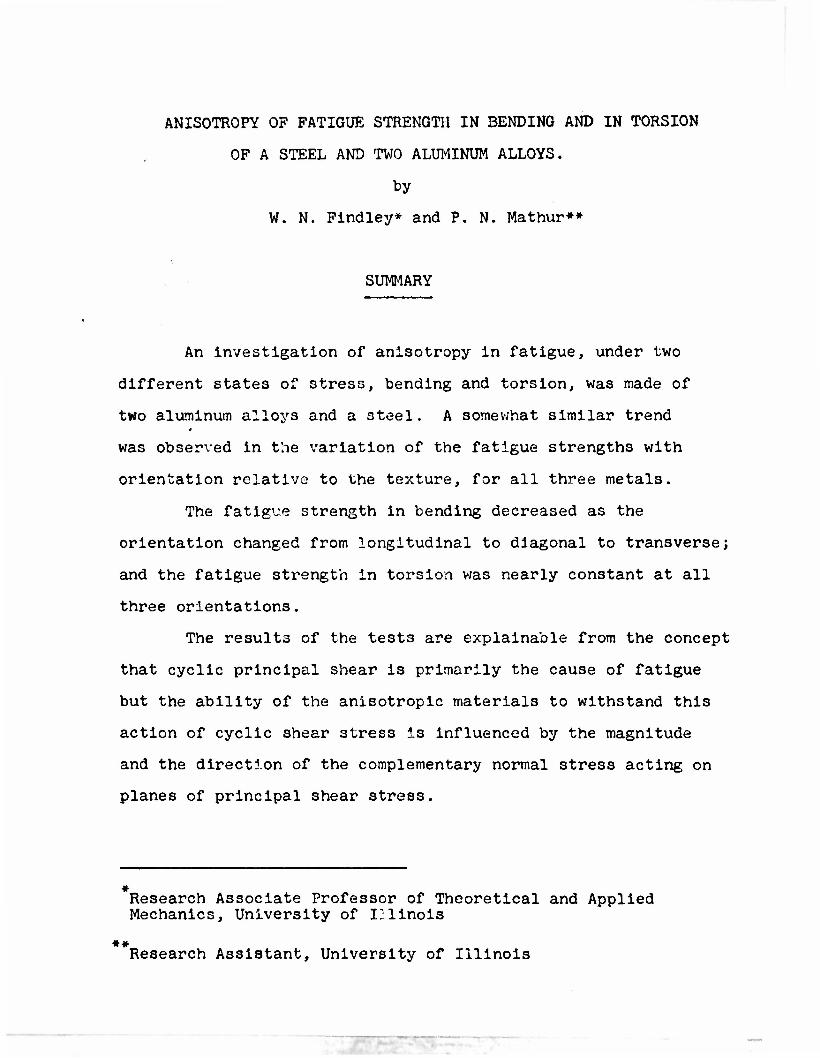
An investigation of anisotropy in fatigue, under two
different states of stress, bending and torsion, was made of
two aluminum alloys and a steel. A somewhat similar trend
was observed in the variation of the fatigue strengths with
orientation relative to the texture, for all three metals.
The fatigue strength in bending decreased as the
orientation changed from longitudinal to diagonal to transverse;
and the fatigue strength in torsion was nearly constant at all
three orientations.
The results of the test3 are explainable from the concept
that cyclic principal shear is primarily the cause of fatigue
but the ability of the anisotropic materials to withstand this
action of cyclic shear stress is influenced by the magnitude
and the direction of the complementary normal stress acting on
planes of principal shear stress.
» Research Associate Professor of Theoretical and Applied Mechanics, University of Illinois
** Research Assistant, University of Illinois
•2-
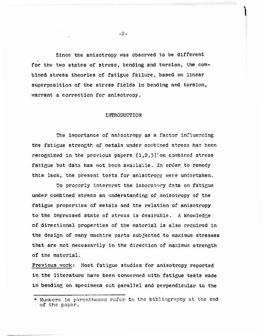
Since the anlsotropy was observed to be different
for the two states of stress, bending and torsion, the com-
bined stress theories of fatigue failure, based on linear
superposition of the stress fields in bending and torsion,
warrant a correction for anlsotropy.
INTRODUCTION
The importance of anjsotropy as a factor influencing
the fatigue strength of metals under combined stress has been
recognized in the previous papers (1,2,5)"on combined stress
fatigue but data has not been available. In order to remedy
this lack, the present tests for anisotropy were undertaken.
To properly interpret the laboratory data on fatigue
under combined stress an understanding of anisotropy of the
fatigue properties of metals and the relation of anisotropy
to the impressed state of stress is desirable. A knowledge
of directional properties of the material is also required in
the design of many machine parts subjected to maximum stresses
that are not necessarily in the direction of maximum strength
of the material.
Previous work: Most fatigue studies for anisotropy reported
in the literature have been concerned with fatigue tests made
in bending on specimens cut parallel and perpendicular to the
1
* Numbers in parentheses refer to the bibliography at the end of the paper.
->
direction of the grain of the stock. The anisotropy was in-
dicated by the comparative fatigue strengths (or percent
variation) in the two directions.
A survey of the results of these fatigue investigations
indicates a varying degree of anisotropy in different steels and
aluminum alloys. (See Table I).
A very high degree of anisotropy was observed in several
studies; particularly those on SAE 4j40 steel forgings (4,5,6),
on heat treated steels (7), and on different Ni, Ni - Cr steels
(8,9,10).
Fatigue tes~s of aluminum alloys (11,12) indicate high
anisotropy in aluminum alloys. Other imvutiro.tors (13,1^,15)
studying different steels md aluminum alloys reported very little
or no evidence of anisotropy.
In the tests of similar nature the influence on the
anisotropy of variables such as the degree of forging reduction
(16,17,18), location of the forged piece in the billet (16),
stress gradient (notches) (16), etc. was observed. To the
knowledge of the authors fatigue tests for anisotropy in
torsion have been reported only in two instances. Von Rosslng
(19) reported results of fatigue tests on Cr - Mo and Ni - Cr - Mo
steel forgings. His data indicated little or no anisotropy in
torsional fatigue and rather pronounced anisotropy in bending
fatigue.
1
•4-
Recently Ransom (6) reported results of torsion & bonding
fatigue tests for anisotropy of SAE 4240 steel forgings. He
observed that most cracks initiated at inclusions for all
orientations in torsion and only for transverse orientations
in bending.
The literature on anisotropy of the static properties
of metals have been reviewed in detail by Barrett (20).
Purpose and scope of the investigation: The present study was
begun in September 1950 to investigate the influence of aniso-
tropy on the fatigue properties under two different states of
stress for three materials used in an investigation of fatigue
of metals under combined bending and torsion (1,2,5,21,22,23,24).
The investigations for anisotropy covered SAE 4340
steel and 76S-T61 and 25S-T6 aluminum alloys. Fatigue tests
on these metals v/ere conducted both in bending and torsion on
miniature specimens, having their axes in longitudinal, diagonal
and transverse directions relative to the axes of the one inch
rolled bar3 from which the specimens for combined bending and
torsion v/ere prepared.
MATERIALS, SPECIMENS AND TEST PROCEDURE
Materials; The materials tested v/ere 76S-T61 and 25S-T6 aluminum
alloys and SAE 4}4o steel quenched and tempered to a hardness of
•5-
Rockwell C 25. The materials were received in the form of
one-inch diameter hot-rolled bars. Details of composition
and heat treatment are given for the three materials in
references (1), (2) and (21) respectively. The specimens from
SAE 4j4o steel were not subjected to the vacuum drawing opera-
tion employed in reference (21). This resulted in slightly
higher hardness in the present specimens.
Preparation of specimens; All fatigue specimens were of the
miniature type, 3A" long, 2/02" minimum diameter and 5A6"
radius as shown in Fig. 5 of reference (25). These specimens
had a Neuber stress concentration factor in bending of 1.09
and in torsion 1.04. All specimens were polished dry with
No. 1, 2/0 and 4/0 carborundum paper wound around a 1/4"
diameter rotating spindle.
All static tensile specimens were of the miniature type
and were prepared in the laboratory of the Aluminum Company of
America in the manner described in reference (25).
The fatigue specimens of 76S-T0I aluminum alloy were
cut from several rectangular blocks machined from the round
bars. The radial orientations of the specimens were recorded
and specimens were tested in sets, in so far as possible, so
that at each stress a longitudinal, diagonal and transverse
specimen were tested from the same block. The static tension
.6-
specimens were prepared with the same orientations from parts
of larger fatigue specimens which had previously been tested.
Fatigue specimens of 25S-T6 aluminum alloy were all
cut from one continuous bar because it had been observed in
tension tests of this material that the surface roughened
during yielding with an uneven "grain" size varying from
small to large in alternate quadrants. Metallurgical examina-
tion and hardness measurements also indicated a variable grain
size. All fatigue specimens with longitudinal, diagonal and
transverse orientations, except six, were prepared from two
slabs cut as close to the center of the bar as possible and
parallel to the diameter of greatest hardness. The six specimens
were oriented transverse to the bar and perpendicular to the slab.
Unfortunately this procedure v.-as not followed in
the static tension specimens. The specimens were machined from
short ends of bars so tht.t the radial orientation of the speci-
mens is not known.
Fatigue and static tension specimens of SAE kjko steel
were prepared in the same manner as the 25S-T6 aluminum specimens
except that the fatigue specimens were machined from several
short ends of bars selected for uniform hardness. The radial
orientation was not controlled.
•7-
Static Tests: The static tests on these materials were made
at the Research Laboratory of the Aluminum Company of America
on special equipment for static tensile tests of miniature
specimens (26,27). For each material, duplicate tensile tests
were made on .05 in. diameter specimens, having longitudinal,
diagonal and transverse orientations. The details of these
tests v/ere described in a report by Babllon (23).
Metallurgical Tests: The photomicrographs of longitudinal
sections were taken near the center of the bars of all three
alloys. These photoir.icrocraphs are shown in Figure 1.
Fatigue Testa: The fatigue tests './ere conducted in constant
amplitude-of-deflection type Krouse faticue machines modified
by a specially designed fixture (25). Trie details of the
specimens, the fixture, the method of loading of specimer3 in
bending and torsion, and the test procedure have been described
in reference (25). Because the geometry of crack formation
frequently permitted the machine to continue running after the
specimen had fractured, specimens in torcion were inspected
with a magnifying glass every 10 minutes to detect cracks. For
bending tests a slight tensile load applied by a flexible coil
spring solved the problem.
The diameter of each specimen was measured by means of
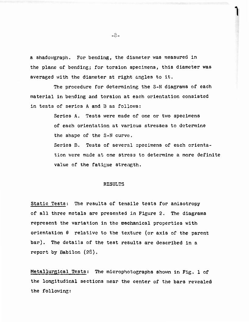
-8-
a shadowgraph. For bending, the diameter was measured in
the plane of bending; for torsion specimens, this diameter was
averaged with the diameter at right angles to it.
The procedure for determining the S-N diagrams of each
material in bending and torsion at each orientation consisted
in tests of series A and 3 as follows:
Series A. Tests were made of one or two specimens
of each orientation at various stresses to determine
the shape of the S-N curve.
Series D. Tests of several specimens of each orienta-
tion were made at one stress to determine a more definite
value of the fatigue strength.
RESULTS
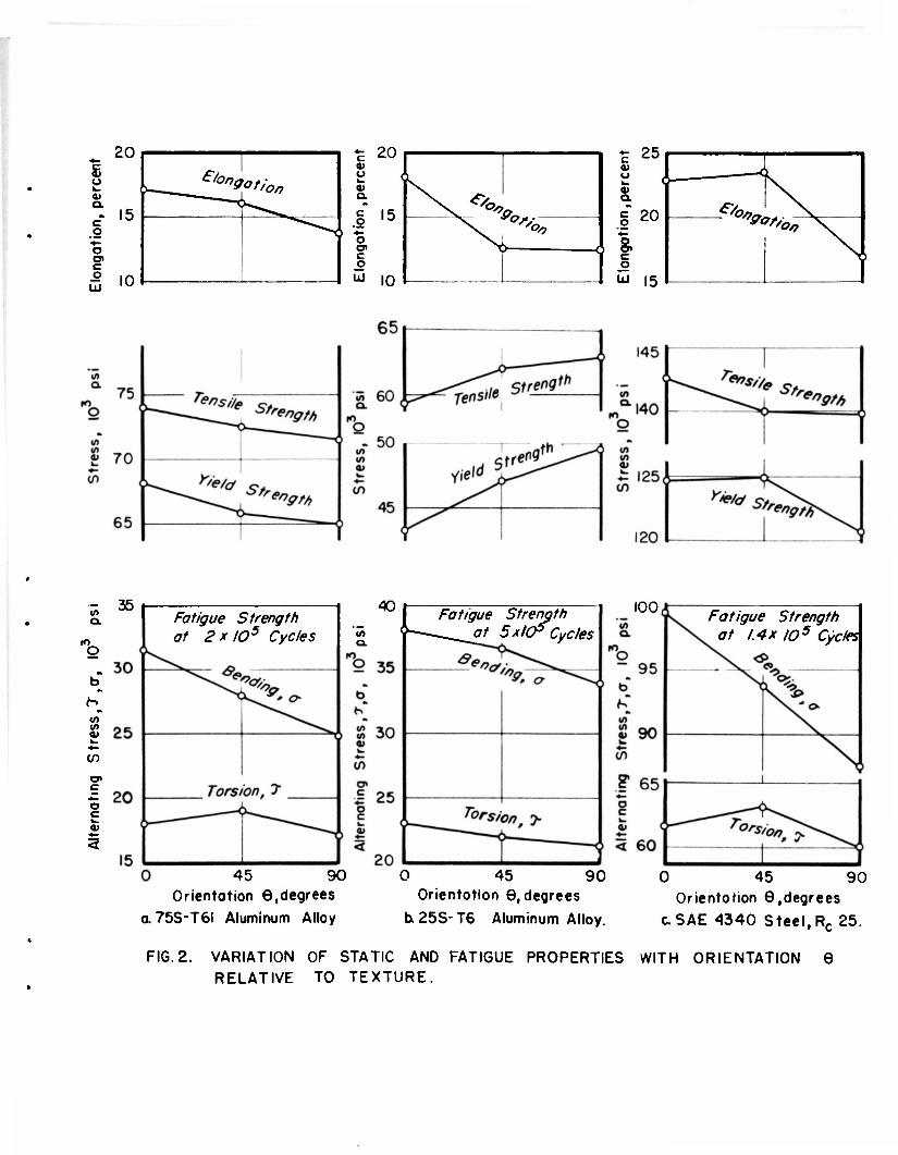
Static Tests: The results of tensile tests for anisotropy
of all three metals are presented in Figure 2. The diagrams
represent the variation in the mechanical properties with
orientation 8 relative to the texture (or axis of the parent
bar). The details of the test results are described in a
report by Babilon (28).
Metallurgical Tests: The microphotographs shown in Fig. 1 of
the longitudinal sections near the center of the bars revealed
the following:

-9-
25S-T6 Aluminum Alloy: This alloy had a uniform dis-
tribution of fragmented Al Cu Pe Mn inclusions and a
few Cu Al globules in the direction of working. The
inclusion content of this alloy was high.
76 S-TSl Aluminum Alloy: There were fewer inclusions
than in the 25S-T0 alloy, mostly of Al Cu Pe and
Al Cu Pe Mn forming an inclusion texture in the direction
of working.
SAE 4j4o Steel: The structure had a highly banded
distribution of carbides in the direction of rolling.
Microphotographs of an unetched surface revealed
elongated plastic inclusions, less than lA inch
long at a magnification of 250 X, aligned along the
same direction.
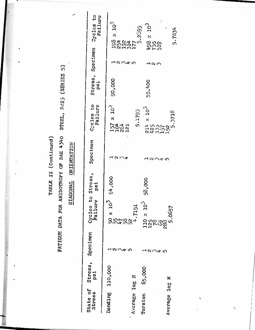
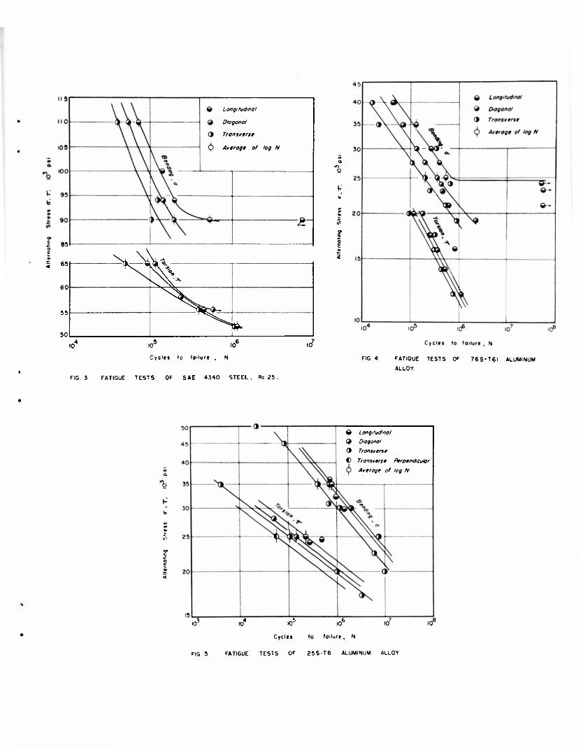
Fatigue Tests: The data obtained from fatigue tests described
in the preceding sections is presented in the form of S-N
diagrams in Figures J>,^f8e 5.Data obtained from Series 3 tests
are summarized in tables II and III. The data points in the
S-N diagrams represent individual specimens of series A and
stress versus the average log N of n specimens of series B,
see Tables II and III.

-10-
The fatigue strengths in bending and torsion interpolated
from the S-N curves at a given member of cycles are presented
in Figure 2, together with the static properties, as a function
of the orientation 0 relative to the texture. For all three
metals, the fatigue strength in bending decreased from longi-
tudinal to diagonal to transverse, with the diagonal value
nearly intermediate between the other two.
The fatigue strength in torsion did net change as much
as in bending. It was the highest in the diagonal direction
for two metals and highest in the longitudinal direction for
25S-T6 aluminum. In all three materials the fatigue strength
in torsion of transverse specimens was the lowest.
V/hile the data points in Fig. 2 are connected by
straight lines for clarity of presentation it is recognized
that curves are more likely relations since the diagrams in
Fig. 2 are only one quadrant in a repeating pattern duplicated
directly or in inverse in other quadrants, and abrupt changes
in the relations with orientation are not likely.
There seems to be rather strong evidence that an en-
durance limit existed in the 76S-T0I aluminum alloy in
bending as shown in Fig. k. The only other evidence (29) known
to the authors of an endurance limit in aluminum alloys indicated o
that the endurance limit of 75S-T6 was reached at about 10
cycles. In the present tests the endurance limit was reached
at about 10 cycles.

The variations of the static and fatigue properties in
the transverse direction expressed in percentage of the longi-
tudinal values were as follows:
76S-T61 aluminum alloy: Bending fatigue strength - 17.0$
torsion fatigue strength - 4.4$, tensile strength - 3-2%
yield strength -4.7$ and percent elongation - 19.8$.
25S-T6 aluminum alloy: Bending fatigue strength - 11.0$
torsion fatigue strength - 7A%, tensile strength
+ 5.95S, yield strength + 14.556 and percent elongation
- 51.356.
SAE 4^40 Steel: Bending fatigue strength - 12.0$,
fatigue strength in torsion - 2.9$, tensile strength
- 2.0$, yield strength - J>.2% and percent elongation
- 25.4$.
The fatigue strength of 25S-T6 aluminum alloy in torsion
for transverse specimens perpendicular to the plane of greatest
strength (designated as the transverse-perpendicular orientation)
was found to be about 6.6 percent less than the corresponding
value in the plane of greatest strength.
In torsion tests of miniature specimens of the 25S-T6
aluminum alloy it was observed that the initial crack propa-
gation appeared to be on longitudinal planes of the longitudinal
specimens and along transverse planes of the transverse
1
-11-

•12-
specimens. This indicates a lower resistance to fatigue
fracture in shear alone planes containinG the direction of the
texture.
The fact that the tensile strength data for 25S-T6
aluminum alloy was higher transverse to the bar than longitudinal
is difficult to explain. It may result from variations in
tensile strength along different diameters in the bar as
observed for fatigue strength.
In view of Vi)e different trends for bending and torsion
fatigue strengths it would be of interest to have static torsion
test data also to determine whether the strength in torsion is
greatest in specimens oriented at 45 .
Size Effect
A comparison of the results of the present tests of
longitudinal specimens in bending and torsion may be made with
previous tests (1,2,21) of the sar.ie materials with larger
diameter specimens, 0.26 in. diameter for 763-T6l aluminum
alloy and SAE k^ko steel and 0.30 in diameter for 25S-T6
aluminum alloy.
The present tests of 3/32 inch diameter specimens show
both higher and lower fatigue strength than the larger speci-
mens; the fatigue strength of 76S-T61 aluminum alloy at
2 x 10^ cycles was 16 and 27 percent lower in bending and
torsion respectively; the fatigue strength of 25S-T6 aluminum
alloy at 5 x 10J cycles was 9 and 11 percent higher in bending
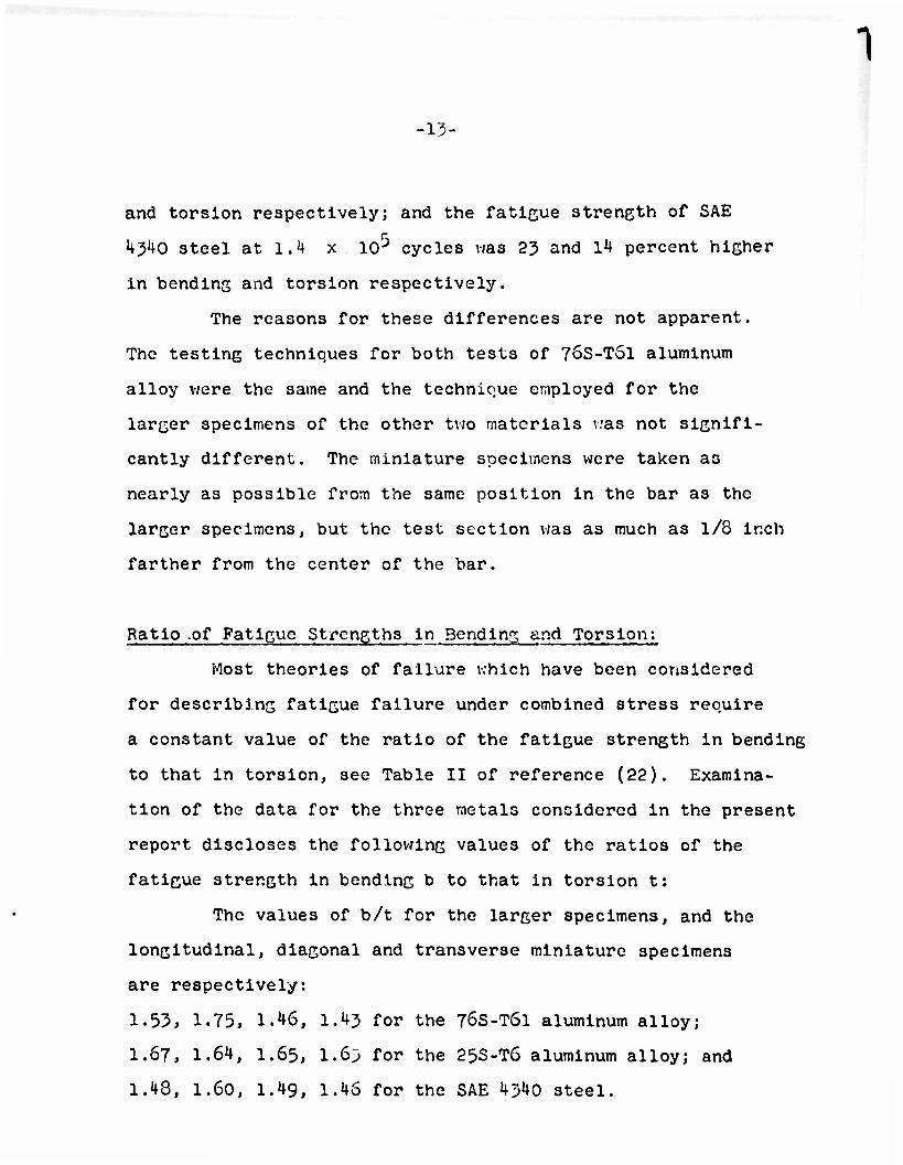
-13-
and torsion respectively; and the faticue strength of SAE
4340 steel at 1.4 x lO^ cycles was 23 and 14 percent higher
in bending and torsion respectively.
The reasons for these differences are not apparent.
The testing techniques for both test3 of 76S-T61 aluminum
alloy were the same and the technique employed for the
larger specimens of the other two materials was not signifi-
cantly different. The miniature specimens were taken as
nearly as possible from the same position in the bar as the
larger specimens, but the test section was as much as 1/8 inch
farther from the center of the bar.
Ratio .of Fatigue Strengths in Bending and Torsion:
Most theories of failure which have been considered
for describing fatigue failure under combined stress require
a constant value of the ratio of the fatigue strength in bending
to that in torsion, see Table II of reference (22). Examina-
tion of the data for the three metals considered in the present
report discloses the following values of the ratios of the
fatigue strength in bending b to that in torsion t:
The values of b/t for the larger specimens, and the
longitudinal, diagonal and transverse miniature specimens
are respectively:
1.53, 1.75, 1.46, 1.43 for the 76S-T6I aluminum alloy;
1.67, 1.64, I.65, 1.6;) for the 25S-T6 aluminum alloy; and
1.48, 1.60, 1.49, 1.4S for the SAE 4;>4o steel.

1
-14-
These values are very consistent for 25S-T6 aluminum
alloy; show considerable difference between materials; and
indicate the highest value for miniature specimens of longi-
tudinal orientation in two of the materials.
ANALYSIS AND INTERPRETATION OF RESULTS
The states of stress, bending and torsion, when
applied to the three orientations, longitudinal, diagonal,
and transverse, can be considered to represent six different
states of stress on an element of anisctropic material. The
fatigue data have been interpreted with the help of diagrams
representing these elements in Figures 6 and 7.
Principal Stress Theory;
Fig. 6 shows the relationship between the direction
of the principal stresses and the texture of the material
(shown by the horizontal lines). If the greatest principal
stress was the important factor in causing fatigue the follow-
ing 3hould be observed: (1) the fatigue strength in bending
should decrease from longitudinal A to diagonal B to transverse
C as observed in Fig. 2.; (2) the fatigue strength in torsion
should be the same in longitudinal R and transverse T specimens
(nearly true for two of the materials); (?) the ratio , B/C of
the fatigue strengths in bending for diagonal specimens to that
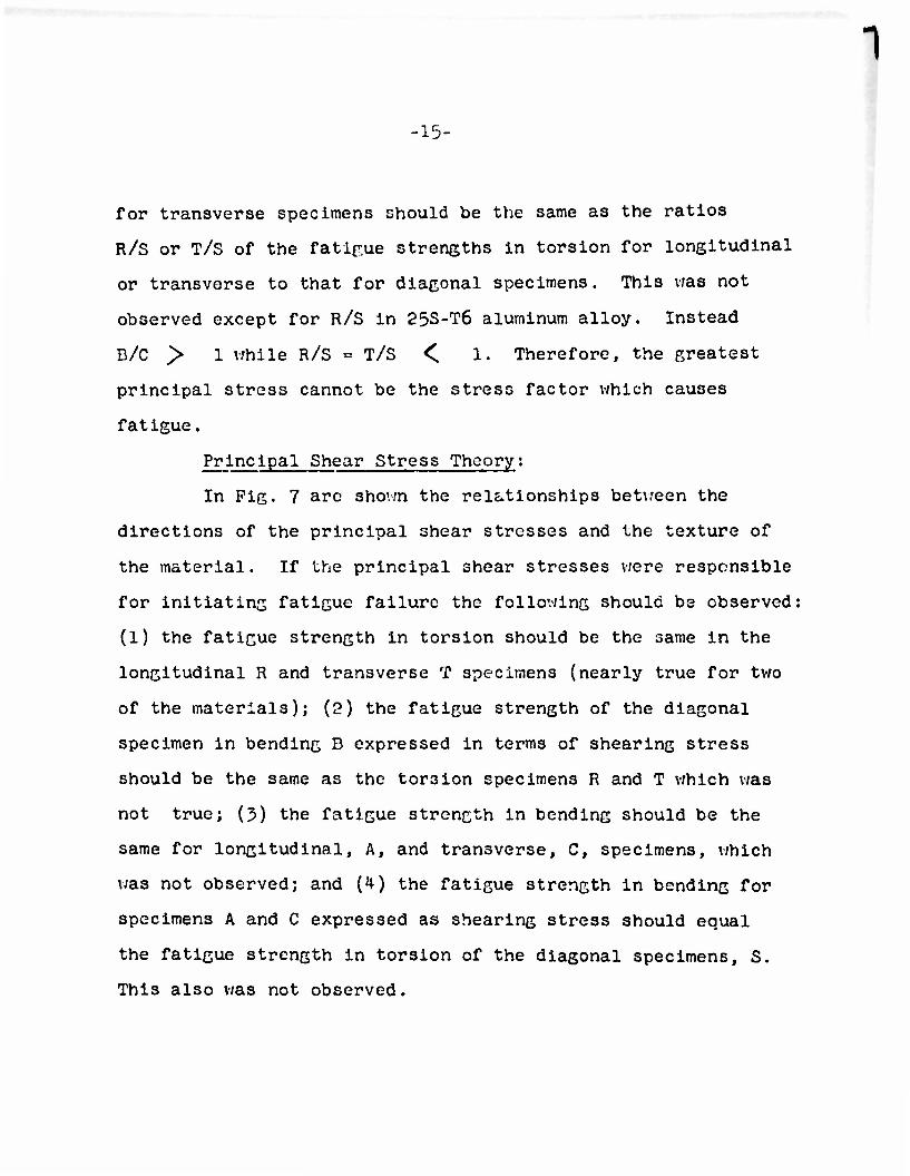
-15-
for transverse specimens should be the same as the ratios
R/S or T/S of the fatigue strengths in torsion for longitudinal
or transverse to that for diagonal specimens. This was not
observed except for R/S in 25S-T6 aluminum alloy. Instead
D/C > 1 v;hile R/S = T/S <. 1. Therefore, the greatest
principal stress cannot be the stress factor which causes
fatigue.
Principal Shear Stress Theory:
In Fig. 7 arc shovm the relationships between the
directions of the principal shear stresses and the texture of
the material. If the principal shear stresses were responsible
for initiating fatigue failure the following should be observed:
(1) the fatigue strength in torsion should be the same in the
longitudinal R and transverse T specimens (nearly true for two
of the materials); (2) the fatigue strength of the diagonal
specimen in bending B expressed in terms of shearing stress
should be the same as the torsion specimens R and T which was
not true; (J>) the fatigue strength in bending should be the
same for longitudinal, A, and transverse, C, specimens, which
was not observed; and (4) the fatigue strength in bending for
specimens A and C expressed aa shearing stress should equal
the fatigue strength in torsion of the diagonal specimens, S.
This also was not observed.
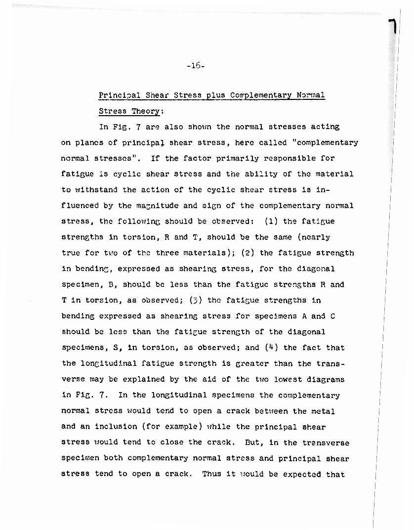
• 16-
Principal Shear Stress plus Complementary Normal
Stress Theory;
In Fig. 7 are also shown the normal stresses acting
on planes of principal shear stress, here called "complementary
normal stresses". If the factor primarily responsible for
fatigue is cyclic shear stress and the ability of the material
to withstand the action of the cyclic shear stress Is in-
fluenced by the magnitude and sign of the complementary normal
stress, the following should be observed: (1) the fatigue
strengths in torsion, R and T, should be the same (nearly
true for two of the three materials); (2) the fatigue strength
in bending, expressed as shearing stress, for the diagonal
specimen, D, should be less than the fatigue strengths R and
T in torsion, as observed; (5) the fatigue strengths in
bending expressed as shearing stress for specimens A and C
should be less than the fatigue strength of the diagonal
specimens, S, In torsion, as observed; and (4) the fact that
the longitudinal fatigue strength is greater than the trans-
verse may be explained by the aid of the two lowest diagrams
in Fig. 7. In the longitudinal specimens the complementary
normal stress would tend to open a crack between the metal
and an inclusion (for example) while the principal shear
stress would tend to close the crack. But, in the transverse
specimen both complementary normal 3tress and principal shear
stress tend to open a crack. Thus it would be expected that
1 -17-
the transverse specimen would be weaker.
The above analysis suggests that the principal stress
and principal shear stress theories are not applicable, but
that the theory of the principal shear stress plus the com-
plementary normal stress may be applicable to fatigue.
INFLUENCE OF ANISOTROPY ON COMBINED STRESS FATIGUE
The results of the tests on all three materials
indicate that the influence of anisotropy on the fatigue
strength is considerably different for the two states of
stress, bending and torsion.
The fatigue strength of these metals under combined
bending and torsion will then be influenced by anisotropy.
Its effect will depend on the relative magnitudes of the
bending and torsicnal components of stress,
A theory predicting the fatigue strength cf metals
under combinations of two different states cf stress like
bending and torsion, therefore cannot be based on the linear
superposition of the two stress fields without accounting for
anisotropy.
In discussion of a previous paper (30) a method of
correcting theories of failure for anisotropy was proposed
for the special case of combined bending and torsion and
-18-
applied to data on fatigue under combined bending and torsion
(1,2,3). Now that data on anisotropy of these same materials
are available it is proposed for a later time to reexamine
the correction for anisotropy, and the relations between
theories of failure and the available test data.
CONCLUSIONS
(1) For all three materials, the fatigue strength
in bending decreased as the orientation changed
from longitudinal to diagonal to transverse
direction. Similar trends were observed for ten-
sile strengths and yield strengths of SAE 43*10
steel and 76S-T61 aluminum alloy. For 25S-T6
aluminum alloy, this trend was reversed for tensile
properties.
The variation in percent elongation (ductility)
was consistent with the variations in bending
fatigue in longitudinal and transverse directions
but was inconsistent in the diagonal direction.
(2) The variation in the fatigue strength in torsion
with direction of the working texture was smaller
than in bending. For 76S-T61 aluminum alloy and
SAE 4340 steel the fatigue strength in torsion
was greatest in the diagonal orientation.

-19-
(5) Since the influence of anisotropy on the
fatigue strength of metals v;a3 not independent of
the state of stress in bending and torsion, the
fatigue strength under combinations of the two
stresses will be influenced by anisotropy. Con-
sequently, the classical theories for combined
stress fatigue based on linear superposition of
stress fields in bonding and torsion warrant a
correction for anisotropy.
(U) The results of fatigue tests are explainable from
the concept that the cyclic principal shear stress
is primarily responsible for fatigue but the
ability of anisotropic materials to withstand the
action of cyclic shear stress is influenced by
the magnitude and sign of the complementary
normal stress.
-20-
ACKNOWLEDGMENT
This project was conducted in the Department of
Theoretical and Applied Mechanics of the University of
Illinois as a part of the work of the Engineering Station.
The authors wish to acknowledge the financial assistance of
the R-search Board of the Graduate School of the University
of Illinois and the Office of Ordnance Research, Ordnance
Corps, Department of the Army.
The authors are greatly indebted to D. M. Sen,
D. R. Burnett, W. P. Wendt, D.D. Strohbeck, and W. A. Hagemeyer
for performing tests and assisting in the analysis of test
data, and to Professor R. W. Bohl for the metallurgical
analysis and photomicrographs.
The cooperation of R. L. Templin, P. M. Howell, and
C. F. Babilon of the Aluminum Company of America in performing
static tension tests of miniature specimens for this project
is gratefully acknowledged.
1
-21-
DIBLIOGRAPHY
1. VI. N. Findley, "Combined Stress Fatigue Strength of
76S-T61 Aluminum Alloy with Superimposed Mean Stresses
and Corrections for Yielding," TN2924, N.A.C.A. May, 1953.
2. W. N. Findley, W.I. Mitchell and D. E. Martin, "Combined
Bonding and Torsion Fatigue Tests of 253-T Aluminum Alloy"
Technical Report No. 1 on Contract No. DA-11-022-0RD-995
Department of the Army, January, 1954.
3. VI. N. Findlcy, VJ. I. Mitchell and D. D. Strohbeck, "Effect
of Range of Stress in Combined Bonding and Torsion Fatigue
Tests of 25S-T Aluminum Alloy," Technical Report No. 2,
on Contract No. DA-11-022-ORD-995, Department of the Army
April, 1954.
4. J. T. Ransom and R. F. Mehl, "The Statistical Nature of
the Fatigue Properties of SAE 4340 Steel Forgings",
Symposium on Fatigue, with Emphasis on Statistical Approach
II, Am. Soc. Testing Materials, p. 3 (1953) (Issued as
A.S.T.M S.T.P No. 137)
5. J. T. Ransom and R. F. Mehl: "The Anisotrcpy of the Fatigue
Properties of SAE 4 240 Steel Forgings", Proceedings, Am.
Soc. Testing Materials, Vol. 52, p. 779 (1952).
6. J. T. Ransom, "The Effect of Inclusions on the Fatigue
Strength of SAE 4340 Steels." Proceedings, Am. Soc. for
Testing Materials, Vol. 53, 1953.

-2"c
7. H. Cornelius and H. Krainer, "Strength Properties of
Heat Treated Cr-Mg-Mo Steels" Stahl und Eisen, Vol. 6l
pp. 871-377 (19^1)
3. Pomey and Ancelle "Introduction to the Study of Corrosion
Fatigue". Hemoires des travaux de la Commission d'etude
de la Corrosion des produits metallurgicjues de 1'Aviation
(1935-36)
11 11
9. A. Junger ' "Erfahrungen uber die Prufung der Dauerfestigkeit
verschicdener Uerk-stoffe auf der MAN-Biege schwingungma-
chine." Mittcilungen aus dom Forschungs Anstalten. vol. 1
pp. 8-18 (1930).
10.R. Mailander "Uber die Dauerfestigkeit von Gusseisen,
Temperguss, und Stahl guss. " Technische Mitteilung Krupp
Vol. 3, PP 59-66 (1936).
ll.Berner and Kastron, "Influence of the Direction of Fiber
on the Resistance to the Fatigue of an Al -Cu-Mg Alloy.
Luffwlscn (Jan. 1938).
12.Joseph Ilarin, "Strength of Steel Subjected to Biaxial
Fatigue Stresses". The Yielding Jour., Vol. 21, pp 55^s-
559s. (Nov, 19^2).
13.L. Aitchison and L. VI. Johnson "The Effect of Grain upon
the Fatigue Strength of Steels" Journal, Iron and Steel
Inst. Vol. Ill pp 351-378. (1925).
-23-
i
14. D. 0. Morris, "Composition and Physical Properties of
Steel in Relation to Fatigue." Symposium on Failure of
Metals by Fatigue, University of Melbourne, Preprint 20
PP- 336 > December, 1946.
15. R. L. Templin, F. M. Howe 11, and E. C. Hartmar.n, "Effect
of Grain Direction on the Fatigue Properties of Aluminum
Alloys." Frcduct Engineering, Vol. 21, No. 7, PP 126-130
(July 1950) .
16. R. Cuzaud "la Fatigue des Met&ux." Third edition, Dunod
(Paris) pp lCl-137 (1948).
17. M. V. Schmidt, "Iniluence of ;he Forging Reduction and
Keat Treatment on the Bending Fatigue Strength of Various
Alloy Structural Steels." Archiv. fur das Eisenhuttenv;esen
vol. 11, pp 393-400 (1937-58).
18. H. Krainer "The Effect of the Degree of Reduction by
Forging on the 3cnding Fatigue Strength of Low Alloy
Steels Parallel and Right Angle to the Forging Direction".
Archiv fur das Eisenhuttenwesen, vol. 15, pp 543-6 (1942).
19. G. F. Von Rossing, :"The Dending Fatigue Strength in
Transverse and Longitudinal directions". Archiv. tZc da3
Eisenhuttenwesen, vol. 15, pp 407-412 (1942).
20. C. S. Barrett, "Structure of Metals" McGraw-Hill Book Co.
Inc., pp 443-460 (1943).
1 -24-
21. B. C. Hanley, "Effect of Range of Stress and State of
Stress on the Fatigue Strength of SAE 4340 Steel," Tech.
Report No. 22 on Contract No-ori-71,T.O.IV, U.S. Navy,
(Feb. 1951).
22. W. N Findley, "Fatigue of 76S-T0I Aluminum Alloy Under
Combined Bending and Torsion" , Proceedings, Am. Soc. for
Testing '"Materials, Vol. 52, p. 818-832. (1952).
23. VJ. N.Findley, "Effect of Range of Stress on Fatigue of
76S-T61 Aluminum Alloy Under Combined Stresses V.'hlch
Produce Yielding," Journal of Applied Mechanics, vol. 20
No. 3, pp 365-37^. (Sept. 1953) .
24. W. N. Findley, F.C. Mergen, A. N. Rosenberg, "The Effect
of Range of Stress on Fatigue Strength of Notched and
Unnotched SAE 434o Steel in Bending and Torsion."
Proceedings, Am. Soc. for Testing Materials, Vol 53, (1953)
in press.
25. W. N. Findley, P G. Jones, W. I. Mitchell and R. L.
Southerland, "Fatigue Machine for Low Temperature" and
For Miniature Specimens, presented at the Annual Meeting
of Am. Soc. for Testing Materials, New York, June 25, 1952.
26. R. L. Templln and VJ. C. Aber, "A Method for Making Tension
Tests of Metals Using a Miniature Specimen," Proceedings,
Am. Soc. for Testing Materials, vol, 50, pp 1188 (1930).
-25-
27. R. L. Tempiin, "An Automatic Autographic Extcnsometer
for Use in Tension Tests of Materials," Proceedings,
Am. Soc. for Testing Materials, vol., 32 Part II p 733
(1952).
28. C. P. Dabilon, "Directional Tensile Properties of SAE 4340
Steel, 25S-T6 and 76S-T61 Rolled Rode." Report No. 9-54-13
Alcoa Aluminum Research Laboratories, Aluminum Company of
America, New Kensington, Pa., March 29, 1954.
29. T. T. Oberg, "When Will it Fail?", Metal Progress, p. 74
(July 1951).
30. W. N. Findlcy, Discussion of "Engineering Steels Under
Combined cyclic and Static Stresses: by H. J. Gough,
Journal of Applied Mechanics, vol. 18, iJo. 2, p 211-213,
(June, 1951).
1

TABLE I REDUCTION IN FATIGUE STRENGTH FROM THE LONGITUDINAL
TO TRANSVERSE DIRECTION
Metal Reduction, Percent
Refe rence Remarks
Ni- Steel 21.3 J. ] Pomey (16) Ni-Steel ^5.0 11 n
Cr-Steel 13.1 n 11
Cr-Steel 1 C S r 11 11
Cr-Mo Steel 26.8 n 11
Nl-Cr Steel 40.0 11 11
Ni-Cr Steel 15.7 11 11
Nl-Cr Steel 37.3 Pomey \ and Ancella (3),(16) Solid Specimens Ni-Cr Steel 1.6 11 11 n n 11 Notched Specimens Steel 4.5 M. Perrin (16) Location:Surface
it 14.5 11 11 Between surface and center
ii 17.5 11 11 Center
Ni-Cr-Mo Steel 30.0 Von Rossing (19) Location:Surface it II n II 17.0 ti n Center
Cr-Mo-Steel 8.0 11 11 Surface M 11 II 2.5 11 11 Center Ni-Cr-Mo Steel 17.7 M. Lioret m Steel 15.0 Schmidt Steel 7.0 11 H
Steel 11.4 n 11
Steel 28.5 11 11
Cr-Ni Steel 13.3 R. Mailander (10) Cr-Ni Steel 21.0 u II
Cr-Ni Steel 22.0 ti II
Ni Steel 23.8 A. Junger (9\ nil Duralumin 20.0 Derner and Koste
SAE 4340 Steel 32.0 Ransom and Mehl (*),(5 Guntube Steels 16.0 u n it 11
SAE 4340 Steel 48.0 Ransom (6) Steel Foruinc 30.0 n n
l4S-T,24S-T 30-35 Mar in (12) al. alloys

a CO IH H ry« p*H w CO *—"
LPV C\J o cr:
*» •H" M 5= W o EH M 00
< O EH -=r S K> w -H-
a; w o M < M CO •J!
w fc s J o M1
3 >< g! EH HH EH|
O Ml K o EH O CO
5 Si
HS s <
K O fe
< £H < a
B o r-H EH <
O •!•> a
U co 3 O rH rH TH O Cj
o
c o e •H CJ cu Ci
CO
w 01 O CO
P CO
a
o P o
u co 3 O iH rH -H CJ (Tl
o
c o E •H CJ o a
co
S9 03 tH (1) CO u a P CO
o •P O
03 3 O rH rH «H o a
c_>
c o E •H CJ QJ a
CO
CO CO rH CJ 03
•p CO
tH CO O CO
o CD U
•p +> cdco
•p CO
n>
o rl
x &
-=T OJ K\ rH . t- m CM co m
rH CM ^"\JH-
o o o o CA
X ON
c )s*cn t^cvj CVJ co co o> • CJ r-l CVJ eH LO
H OJ n^
o o o
o>
^o
<H CM r-\
o o o
•H •o c <u cq
o
X V0 3S
OJ-=l- Ao\AO lAiH t-aj O O K>0.=r r-^rH .
OJ rH f<A
<-< CM h'N.sf U"\
O a o
* OJ
(A o rH
x in ro o i-vo OJ ,r\ VO LPVOJCO OJ • f^oj nw-^oo m
r-t OJ r\.H- m
o o at m m
o
VD CAOJ
o 0>
r-i OJ l"\
O o o
•» 2 in
VO to o
r-H
CD c to o «$ •H u CO cu h > 0 , <; EH
to o
o to co- in
en
CO w
CO
TJ o -3- o iA S
3 * o C M •H W H P < < c o CO
o ft, W ^-^ o rH
H >< g M a,
O
a 6 < a o s < CO o e* M o
2 < < K
§ < EH < Q
B o M E- < ft*
O <D •P «u
3 CO (-1 O >H rH (d O ft, >> O
c cu E •H o <u a
co
CO CO -H <u co
•p CO
O O -P u
3 CO rH CO -H
rH CTJ O ft,
a
c o E
•H O
a CO
CO CO o •p co
CO a
o •P 0)
co 3 CJ r-t rH -H U CO >>ft, o
c cu B •H O CJ
CO
CO CO O <H SU CO
•p a CO
O CO co
Q> CD •P fc rt -p •p co W
rn O
X
in as co c\j
CO-* t\!-=l- N-in o> m ONVD t- rH C\J rH rHrH
rH CM f.-\j-j- m
o
X
co mo^ CMI^H
Cvj m
o o o
o ON
o
t^r-5t*t <H cnovjj CVJ »"H rH C\J rH
ON
H
m
o o
in m
rn o
X
co rH
.=* iTkKNh-CVJ in >H OJ m m m CVJ ^J- m rH rH
«H CO h>^
O O o
'•H C\J m*- m
8 •ST ON m
2 ri <H ^
f"N
2 **- X O
Qtnt*-vocvi.=* inm^ mm o mco ONCO in *-< Cvj C"-OC0 rH rH CU
H CVJ cn.=i- m
o o o
«H CM r^\j* m
•H
c
O o o s * in
to vo o rH
a> c to o crj •H f- CO O SU > o < rH
to o
o to «5 SU O >

CO W
CO
\
m 04 o K
ft •J fcl 1
'—» CO •o o O 3 .3- C f?N •H -* P c W o < o CO
Dc M O 1-H
SH
a O
§
o
o
w CO
@
u
o -P 0)
w 3 Q) r-t
o cd
o
c o £
o CU a
CO
w CO CO >H J-i CO p a co
o
X
o P o
5-i W 3 O rH
o co ?•>&« o
c o n •H O a
CO
CO co -H O CO u o. P co
o P o
0) 3 0)
o H CO
x o\
CM C\J >H so\m
H OJ m.=i- m
•H «=U o <o
c o £
O <u a co
CO CO -H <U CO
P CO
*-l CO O CO
CU O (4 p p COCO p CO
^t t~ic\KO co o CM OCOCOrH •
r-4 <\j t-Aj* in
o o o
ft o
o o o
o>
o H ON
X 00
OCO CM K\iT\ • inc\»Jt m.^^
rH CM KN.3- in
8 o
ft o r-t r-i
c
&
o
vo co m.-i- co o
vo o\ h- mco vo
<H CM m.^ in
o o o
in
m o
x %
CM CM^l-vO O • 4-voo t^co in t- CM CM O ^J-
r-i OJ m-s- in
o o
in m
o
o^co CM in • rA m.=r .=h CO J*
<H CM KW m
8 m
to KD o
O C to o <0 •H ^ CO CD fc. > o (0 £
£ a>
*

m O
V0 *t mrH mo CM rH f- m.=J- rH 0>
in co CVJ
w M
w
H cvj r^j* mvo
m o
o oo
m
o vO
vo oo mvo t-- m m CT\ m.s*- MD OJ jj-
m o
^ONHm^ <HC0 rHf-O-rH
VO VO CVI O
in
rH CM m^t m*,o h- rH co f\.n- invo
a
o M
< i s M PS o
o m r-l o^
K CO
t«- ov CVJ vo vo oo t- in O CVJ m CVJ rHVO t- OifMACA t>-vO VO
«H OJ .A^- invo f>-
o
CM r-i tn o -* CVJ cr\ •af ^- 01 m O CVJ V.O H rH CVJ rH rH CVJ
o> VO
m
H CVJ m.if mvo •>-
vo r'\ O o»
)co rH i-i^t t^-m • m os mvo m 10-fn^mcvj
m O
cvi ^m«>-vo CVJ in •H CVJJ*-^ CVJ CVJ
m o> m in
o H
<
<H CVJ K\^- mvo l>- <H CVJ f-\j»- mvo o-
V o3
o to g I!

.*!
I
» i
V
*/-v--r.--.*-.v-.?<--\^.••* -.::-:fci '*4
Microphotograph of 76S-T61 Aluminum Alloy (250X)
Microphotograph of 25S-T6 Aluminum Alloy (250X)
-*•
sir'* ' :*T •. .•• *u .y••?. I* . ••••••' „^?v^
• ... ~'*•:•%.
.-*» - , •
. * . , 1 .f1 • . * *»
i->.
i7.*..-.y V
&**«
•
..
Microphotograph of SAE 4340 Steel (250X)
Microphotograph of SAE 4^40 Steel Unetched (250X)
FIG. I MICROPHOTOGRAPHS SHOWING THE TEXTURE OF METALS PARALLEL TO THE AXIS OF THE POLLED BARS.
.1 35 a.
b
(A
a»
CD
C7>
a>
3
Fatigue Strength at 2 x lO5 Cycles
40 Fatigue Strength at 5xlO*Cycles
100,
45 90 Orientation 6,degrees
0.75S-T6I Aluminum Alloy
0 45 90 Orientotion 6, degrees
bi25S-T6 Aluminum Alloy.
Fatigue Strength at 1.4x io5 Cycles
0 45 90 Orientation 6,degrees
cSAE 4340 Steel, Rc 25.
FIG. 2. VARIATION OF STATIC AND FATIGUE PROPERTIES WITH ORIENTATION RELATIVE TO TEXTURE.
6
z 85
10
Longitudmol
Diagonal
Transverse
Average of log N
10 10
Cydft to failure . N
65 VI -A
60
55
^Sv ^vs. *^
^^'^^a
50 1
FIG 4 FATIGUE TESTS OF 76S-T6I ALUMINUM
ALLOY
FIG 3 FATIGUE TESTS OF SAE 1340 STEEL. Re 25.
9 Longitudinal
9 D'ogoioi
O Transverse
© Transverse Perpendicular
Average of log N
FIG 5
10 10 10 10
Cycles to foilure, N
FATIGUE TESTS OF 25S-T6 ALUMINUM ALLOY

Bending
c
t
\
T «
Torsion
Fig 6 Orientation of Principal Stresses Relative to the Texture of the Material in Tests for Anisotropy in the Fatigue Properties.(The direction of the
texture is horizontal).
Bending
Fig 7 Orientation of Principal Shear and Complimentary
Normal Stresses Relative to the Texture of the
Material in Tests for Anisotropy in the Fatigue Properties. (The direction of the texture is
horizontal.)

firmed Services Technical Information Agency Because of our limited supply, you are requested to return this copy WHEN IT HAS SERVED YOUR PURPOSE so that it may be made available to other requesters. Your cooperation will be appreciated.
NOTICE: WHEN GOVERNMENT OR OTHER DRAWINGS, SPECIFICATIONS OR OTHER DATA ARE USED FOR ANY PURPOSE OTHER THAN IN CONNECTION WITH A DEFINITELY RELATED GOVERNMENT PROCUREMENT OPERATION, THE U. S. GOVERNMENT THEREBY INCURS NO RESPONSIBILITY, NOR ANY OBLIGATION WHATSOEVER; AND THE FACT THAT THE GOVERNMENT MAY HAVE FORMULATED, FURNISHED, OR IN ANY WAY SUPPLIED THE SAID DRAWINGS, SPECIFICATIONS, OR OTHER DATA IS NOT TO BE REGARDED BY IMPLICATION OR OTHERWISE AS IN ANY MANNER LICENSING THE HOLDER OR ANY OTHER PERSON OR CORPORATION, OR CONVEYING ANY RIGHTS OR PERMISSION TO MANUFACTURE, USE OR SELL ANY PATENTED DJVENTION THAT MAY IN ANY WAY BE RELATED THERETO.
Reproduced by
DOCUMENT SERVICE CENTER KNOTT BUILDING, DAYTON, 2, OHIO
.^ ..... ,. —..•_,_..„ 1
OFKL ASSIFIED • k—»~WMWW- —. ..VI. .11 i. »• •' ,...!• '• —' <^*MM^BMBii^Ml^MMMWM^MMMIMMMWWI •* SSKrt-- --..*. V^vV~ --<- i miMiM * i IJE