ARM Functional Fixed Hardware Specificationinfocenter.arm.com/help/topic/com.arm.doc.den0048a/...ARM...
14
ARM Functional Fixed Hardware Specification Page 1 of 14 Copyright © 2015 ARM Limited. All rights reserved. ARM DEN 0048A Non-Confidential ARM ® Functional Fixed Hardware Specification Document number: ARM DEN 0048A Copyright ARM Limited 2015
Transcript of ARM Functional Fixed Hardware Specificationinfocenter.arm.com/help/topic/com.arm.doc.den0048a/...ARM...

ARM Functional Fixed Hardware Specification
Page 1 of 14 Copyright © 2015 ARM Limited. All rights reserved. ARM DEN 0048A Non-Confidential
ARM® Functional Fixed Hardware Specification
Document number: ARM DEN 0048A
Copyright ARM Limited 2015

ARM Functional Fixed Hardware Specification
Page 2 of 14 Copyright © 2015 ARM Limited. All rights reserved. ARM DEN 0048A Non-Confidential
ARM Function Fixed Hardware Specification System Software on ARM
Copyright © 2015 ARM Limited. All rights reserved.
Release information
The Change History table lists the changes made to this document.
Table 1-1 Change history
Date Issue Confidentiality Change
17 April 2015 A Non-Confidential First release.
Non-Confidential Proprietary Notice
This document is protected by copyright and the practice or implementation of the information herein may be protected by one or more patents or pending applications. No part of this document may be reproduced in any form by any means without the express prior written permission of ARM. No license, express or implied, by estoppel or otherwise to any intellectual property rights is granted by this document.
This document is Non-Confidential but any disclosure by you is subject to you providing the recipient
the conditions set out in this notice and procuring the acceptance by the recipient of the conditions set out in this notice.
Your access to the information in this document is conditional upon your acceptance that you will not use or permit others to use the information for the purposes of determining whether implementations infringe any patents.
This document is provided “as is”. ARM makes no representations or warranties, either express or implied, included but not limited to, warranties of merchantability, fitness for a particular purpose, or non-infringement, that the content of this document is suitable for any particular purpose or that any practice or implementation of the contents of the document will not infringe any third party patents, copyrights, trade secrets, or other rights. Further, ARM makes no representation with respect to, and has undertaken no analysis to identify or understand the scope and content of such third party patents, copyrights, trade secrets, or other rights.
This document may include technical inaccuracies or typographical errors.
TO THE EXTENT NOT PROHIBITED BY LAW, IN NO EVENT WILL ARM BE LIABLE FOR ANY DAMAGES, INCLUDING WITHOUT LIMITATION ANY DIRECT LOSS, LOST REVENUE, LOST PROFITS OR DATA, SPECIAL, INDIRECT, CONSEQUENTIAL, INCIDENTAL OR PUNITIVE DAMAGES, HOWEVER CAUSED AND REGARDLESS OF THE THEORY OF LIABILITY, ARISING OUT OF OR RELATED TO ANY FURNISHING, PRACTICING, MODIFYING OR ANY USE OF THIS DOCUMENT, EVEN IF ARM HAS BEEN ADVISED OF THE POSSIBILITY OF SUCH DAMAGES.
Words and logos marked with ® or TM are registered trademarks or trademarks, respectively, of ARM Limited. Other brands and names mentioned herein may be the trademarks of their respective owners. Unless otherwise stated in the terms of the Agreement, you will not use or permit others to use any trademark of ARM Limited.
This document consists solely of commercial items. You shall be responsible for ensuring that any use, duplication or disclosure of this document complies fully with any relevant export laws and regulations to assure that this document or any portion thereof is not exported, directly or indirectly, in violation of such export laws.
In this document, where the term ARM is used to refer to the company it means “ARM or any of its subsidiaries as appropriate”.
Copyright © 2015, ARM Limited or its affiliates. All rights reserved. ARM Limited. Company 02557590 registered in England. 110 Fulbourn Road, Cambridge, England CB1 9NJ.

ARM Functional Fixed Hardware Specification
Page 3 of 14 Copyright © 2015 ARM Limited. All rights reserved. ARM DEN 0048A Non-Confidential
Contents
1 ABOUT THIS DOCUMENT 4 1.1 References 4 1.2 Terms and abbreviations 4 1.3 Feedback 4
1.3.1 Feedback on this manual 4
2 INTRODUCTION 4
3 USE CASES 5 3.1 Idle management and Low Power Idle states 5
3.1.1 FFH Usage in LPI state entry methods 5 3.1.2 FFH Usage in LPI residency and usage counter registers 6 3.1.3 Save and restore flags 6
APPENDIX A PSCI STATE COMPOSITION FROM LPI STATES 8 A.1 Original StateID power_state parameter format: PSCI0.2 or above 9 A.2 Extended StateID power_state parameter format: PSCI 1.0 or above 12

ARM Functional Fixed Hardware Specification
Page 4 of 14 Copyright © 2015 ARM Limited. All rights reserved. ARM DEN 0048A Non-Confidential
1 About this Document
This document provides the specification for ARM reserved uses of Functional Fixed Hardware for ACPI-based systems.
1.1 References
This document refers to the following documents.
Reference Document Number Title
[ACPI6.0] ACPI 6.0 Advanced Configuration and Power Interface Specification
[PSCI] ARM DEN 0028 Power State Coordination Interface
1.2 Terms and abbreviations
This document uses the following terms and abbreviations.
Term Meaning
FFH Functional Fixed Hardware. This refers to software (SW) operations that replace a hardware (HW) function.
1.3 Feedback
ARM welcomes feedback on its documentation.
1.3.1 Feedback on this manual
If you have comments on the content of this manual, send an e-mail to [email protected]. Give:
The title.
The document and version number, ARM DEN 0048A.
The page numbers to which your comments apply.
A concise explanation of your comments.
ARM also welcomes general suggestions for additions and improvements.
2 Introduction
This document provides a specification for Functional Fixed Hardware (FFH) in ARM-based systems that use the
Advanced Configuration and Power Interface (ACPI).
At the time of writing, the only use case is:
Idle Management and Low Power Idle (LPI) states. See [ACPI6.0].
ARM Functional Fixed Hardware Specification
Page 5 of 14 Copyright © 2015 ARM Limited. All rights reserved. ARM DEN 0048A Non-Confidential
3 Use Cases
3.1 Idle management and Low Power Idle states
ACPI 6.0 [ACPI6.0] introduces Low Power Idle (LPI) states, which allow an operating system to manage the power states of the processor power domain hierarchy. This section describes how FFH is used in ARM-based systems to allow the operating system to discover:
The entry method into a low power state.
How to collect power state residency, and usage count statistics.
This section also defines the flags used in an LPI state object to describe the architectural context that is lost when the LPI state is entered.
3.1.1 FFH Usage in LPI state entry methods
ACPI ASL uses the Register keyword to define HW register addresses, or SW functions, when using FFH. The Register keyword has the following format:
Register (AddressSpaceKeyword, RegisterBitWidth, RegisterBitOffset, RegisterAddress, AccessSize,
DescriptorName)
For further information, see section 19.6.108 of [ACPI6.0]. Registers are used to specify one of the following two entry methods into an LPI state:
A Wait For Interrupt (WFI) instruction.
A PSCI CPU_SUSPEND call. In this case, the entry method provides a way of describing the
power_state parameter of the CPU_SUSPEND call [PSCI].
When using FFH to describe LPI entry methods, the register field entries must be set as follows:
AddressSpaceKeyword must be set to 0x7f. This denotes usage of the FFH address space.
RegisterBitWidth must be set to 32.
RegisterBitOffset must be set to 0.
AccessSize must be set to 3 (Dword).
WFIs states must be represented in the _LPI objects of processors. In the WFI case, the RegisterAddress
in the entry method of the LPI state has the following format:
Bits[63:32] Bits[31:0]
0x00000000 0xFFFFFFFF
A PSCI power_state parameter is represented in the RegisterAddress field as follows:
Bits[63:32] Bits[31:0]
0x00000000 PSCI power_state parameter for CPU_SUSPEND call. See section
5.4 of [PSCI] for more details.
For LPI entry methods, all other possible encodings of RegisterAddress, RegisterBitWidth,
RegisterBitOffset, and AccessSize where 0x7f is used for the AddressSpaceKeyword are reserved for
future use.
DescriptorName is optional. See section 19.6.108 of [ACPI6.0] for further details.

ARM Functional Fixed Hardware Specification
Page 6 of 14 Copyright © 2015 ARM Limited. All rights reserved. ARM DEN 0048A Non-Confidential
When the OS is working in OS Initiated mode, as defined by both the PSCI [PSCI] and ACPI 6.0 [ACPI6.0] specifications, the OS must regard cores using the WFI state as being in a running state, for the purposes of last
man tracking. To enter OS Initiated mode, the OS must use the PSCI_SET_SUSPEND_MODE call described in
sections 5.1.16 and 5.17 of the PSCI [PSCI] specification.
Appendix A provides a description and examples of how PSCI power states are composed from LPI entry methods and _LPI LevelID. The examples cover platform coordinated and OS Initiated systems.
3.1.2 FFH Usage in LPI residency and usage counter registers
PSCI1.0 introduces the PSCI_STAT_RESIDENCY and PSCI_STAT_COUNT functions. For systems that implement
these functions, ASL Registers in the FFH space can be used for the residency and usage counter register fields of LPI states. This allows matching those registers to a PSCI call. In this case, the format of the Register provided is as follows:
AddressSpaceKeyword must be 0x7f. This denotes usage of the FFH address space.
RegisterBitWidth must be 32.
RegisterBitOffset must be 0.
AccessSize must be 3 (Dword).
For both the residency and usage counter registers, the RegisterAddress field must have the following
encoding:
Bits[63:32] Bits[31:0]
0x00000000 PSCI power_state parameter for PSCI_STAT_* functions.
See section 5.18.1 of [PSCI].
For residency and usage counter registers of LPI entries, all other possible encodings of RegisterAddress,
RegisterBitWidth, RegisterBitOffset, and AccessSize where 0x7f is used for the AddressSpaceKeyword are
reserved for future use.
DescriptorName is optional and can be omitted. See section 19.6.108 of [ACPI6.0] for further details.
In the case of the residency counter register, this encoding instructs the processor driver of the OS to issue a
PSCI_STAT_RESIDENCY call. The residency counter frequency of the LPI must be set to 1000000, to indicate
that the count is in microseconds.
In the case of the usage counter register, this encoding instructs the processor driver of the OS to issue a
PSCI_STAT_COUNT call.
Note: The OSPM must use the PSCI_FEATURES API to ensure that PSCI_STAT_RESIDENCY and PSCI_STAT_COUNT are provided by the PSCI implementation. See [PSCI] for more details.
3.1.3 Save and restore flags
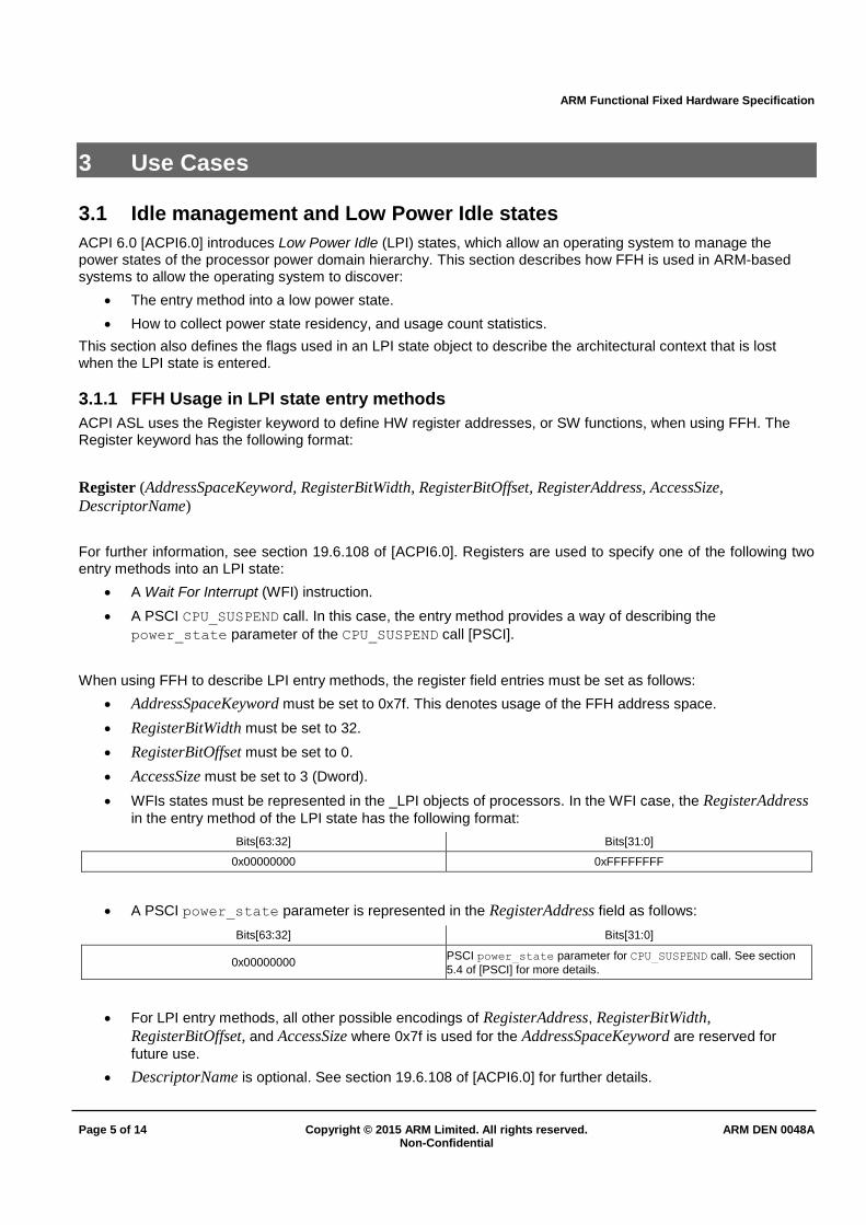
LPI states provide an architectural context loss flags field that can be used to describe the context that might be lost when an LPI state is entered. For ARM-based systems, the flags have the following format:
Table 2 ARM Architecture context loss flags
Flag Bit offset
Bit length
Description
Core context Lost 0x0 0x1 All core context is lost. This includes:
General purpose registers.
Floating point and SIMD registers.
System registers, include the System register based generic timer for the core.
ARM Functional Fixed Hardware Specification
Page 7 of 14 Copyright © 2015 ARM Limited. All rights reserved. ARM DEN 0048A Non-Confidential
Debug register in the core power domain.
PMU registers in the core power domain.
Trace register in the core power domain.
Trace context loss 0x1 0x1 Trace registers outside of the core power domain are lost.
GICR 0x2 0x1 GIC Redistributor logic.
GICD 0x3 0x1 GIC Distributor logic.
Reserved 0x4 0x1c Reserved must be zero.

ARM Functional Fixed Hardware Specification
Page 8 of 14 Copyright © 2015 ARM Limited. All rights reserved. ARM DEN 0048A Non-Confidential
Appendix A PSCI State Composition From LPI states
Section 8.4.4.3.4 of [ACPI6.0] describes how entry methods of local LPI states are composed to produce the final command that is issued to platform firmware to enter a composite power state. This appendix describes how this composition takes place in ARM systems that provide a PSCI implementation. In such systems, the composition
results in the value of the power_state parameter that is passed to a CPU_SUSPEND call to enter the composite
state.
Each LPI state provides an entry method field that is used to determine the PSCI power_state parameter to be
used with a CPU_SUSPEND call. The parameter is composed through the following steps:
1. The OS extracts an initial base power_state parameter from the lower 32 bits of the RegisterAddress
field of the entry method of a processor LPI. For processors, entry methods must be a register that adheres to the definition provided in section see 3.1.1.
2. If the composite power state selected by an OS affects power levels above the processor, the OS must walk the LPI states defined in processor containers above the processor. For the LPI states in those containers, the entry method can be an integer or a register:
a. If the entry method is an integer value, then the base power_state parameter obtained in step 1
must have this integer value added to it.
b. If the entry method defined is a register, then the lower 32 bits of the RegisterAddress field
becomes the new base power_state parameter
This process is repeated across the LPIs that form the target power state. For OS and PSCI firmware
working in platform coordinated mode, the base power_state parameter obtained in steps 1 and 2
forms the final power_state parameter that is passed to a CPU_SUSPEND call.
3. For OS and PSCI firmware working in OS Initiated mode, the OS must indicate the power level in which it observes that the calling processor is the last to go idle. To do so, the OS adds the value of the LevelID
field of the _LPI object [ACPI6.0], defined at the appropriate power level, to the base power_state
parameter, to form the final power_state argument for the CPU_SUSPEND call.
The steps are described in the following pseudocode:
// Initially LPIx points to a processor-level LPI state
LPIx = ChooseLPIStateForLevel(LevelOf(CurrentProcessor),NULL)
power_state = LPIx.EntryMethod.Address
if power_state == uint_64(-1) // WFI case
doWFI()
return
for level = Parent(CurrentProcessor) to system
LPIx = ChooseLPIStateForLevel(level,LPIx)
If LocalState == Run
break
EM = LPIx.EntryMethod
if IsInteger(EM)
power_state = power_state+ZeroExtend(IntegerValue(EM))
else
ARM Functional Fixed Hardware Specification
Page 9 of 14 Copyright © 2015 ARM Limited. All rights reserved. ARM DEN 0048A Non-Confidential
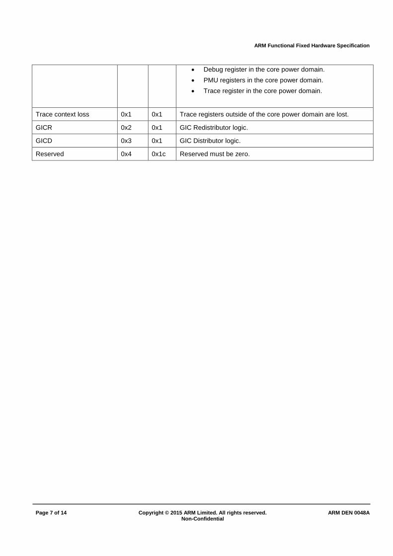
power_state = EM.Address
If IdleMode == OS_Initiated
LastProc = ProcessorContainerWhereCallingIsLastToIdle()
LastProcLPI = LastProc.LPI
power_state = power_state+LastProcLPI.LevelID
doCPU_SUSPEND(power_state)
return
The following sections provide examples of how power states can be represented in systems using the original
StateID power_state parameter format, and the extended StateID power_state parameter format. The first
example applies to PSCI 0.2 or PSCI 1.0, while the second applies only to PSCI 1.0.
A.1 Original StateID power_state parameter format: PSCI0.2 or above
PSCI 0.2 supports only the original power_state parameter format with a 16-bit StateID field. See [PSCI] for
further details. Figure 1 shows an example system.
System Level
Power States:
Retention
Power-down
Cluster Level
Cluster 1
Power States:
Retention
Power-down
Cluster Level
Cluster 0
Power States:
Retention
Power-down
Core Level
Core 0
Power States:
Standby WFI
Retention
Power-down
Core Level
Core 1
Power States:
Standby WFI
Retention
Power-down
Core Level
Core 2
Power States:
Standby WFI
Retention
Power-down
Core Level
Core 3
Power States:
Standby WFI
Retention
Power-down
Figure 1 Example system
Figure 1 shows an example system composed of three power levels, core, cluster, and system. For each power level, the local power states are shown. Our example system PSCI supports the composite power states shown in Table 3.
Table 3 Supported power states in the example system and PSCI power_state parameter encoding in
original StateID format
Composite power state
Core
local state
Cluster
local state
System
local state
PCI power_state
parameter
Retention Run Run 0x00000001
Power-down Run Run 0x00010002
ARM Functional Fixed Hardware Specification
Page 10 of 14 Copyright © 2015 ARM Limited. All rights reserved. ARM DEN 0048A Non-Confidential
Retention Retention Run 0x01000011
Power-down Retention Run 0x01010012
Power-down Power-down Run 0x01010022
Retention Retention Retention 0x02000111
Power-down Retention Retention 0x02010112
Power-down Power-down Retention 0x02010122
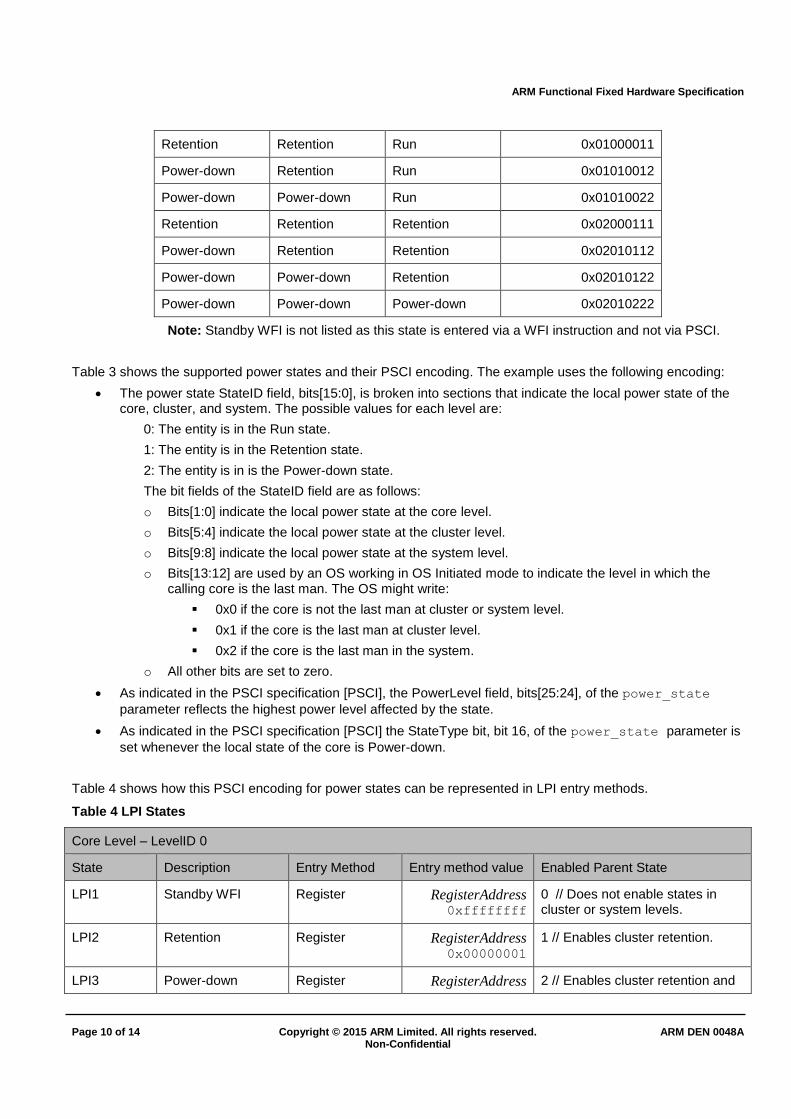
Power-down Power-down Power-down 0x02010222
Note: Standby WFI is not listed as this state is entered via a WFI instruction and not via PSCI.
Table 3 shows the supported power states and their PSCI encoding. The example uses the following encoding:
The power state StateID field, bits[15:0], is broken into sections that indicate the local power state of the core, cluster, and system. The possible values for each level are:
0: The entity is in the Run state.
1: The entity is in the Retention state.
2: The entity is in is the Power-down state.
The bit fields of the StateID field are as follows:
o Bits[1:0] indicate the local power state at the core level.
o Bits[5:4] indicate the local power state at the cluster level.
o Bits[9:8] indicate the local power state at the system level.
o Bits[13:12] are used by an OS working in OS Initiated mode to indicate the level in which the calling core is the last man. The OS might write:
0x0 if the core is not the last man at cluster or system level.
0x1 if the core is the last man at cluster level.
0x2 if the core is the last man in the system.
o All other bits are set to zero.
As indicated in the PSCI specification [PSCI], the PowerLevel field, bits[25:24], of the power_state
parameter reflects the highest power level affected by the state.
As indicated in the PSCI specification [PSCI] the StateType bit, bit 16, of the power_state parameter is
set whenever the local state of the core is Power-down.
Table 4 shows how this PSCI encoding for power states can be represented in LPI entry methods.
Table 4 LPI States
Core Level – LevelID 0
State Description Entry Method Entry method value Enabled Parent State
LPI1 Standby WFI Register RegisterAddress 0xffffffff
0 // Does not enable states in cluster or system levels.
LPI2 Retention Register RegisterAddress 0x00000001
1 // Enables cluster retention.
LPI3 Power-down Register RegisterAddress 2 // Enables cluster retention and
ARM Functional Fixed Hardware Specification
Page 11 of 14 Copyright © 2015 ARM Limited. All rights reserved. ARM DEN 0048A Non-Confidential
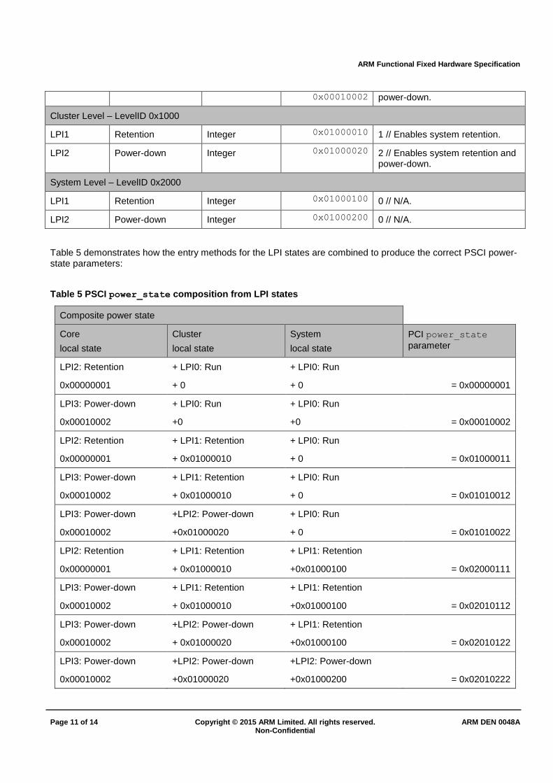
0x00010002 power-down.
Cluster Level – LevelID 0x1000
LPI1 Retention Integer 0x01000010 1 // Enables system retention.
LPI2 Power-down Integer 0x01000020 2 // Enables system retention and power-down.
System Level – LevelID 0x2000
LPI1 Retention Integer 0x01000100 0 // N/A.
LPI2 Power-down Integer 0x01000200 0 // N/A.
Table 5 demonstrates how the entry methods for the LPI states are combined to produce the correct PSCI power-state parameters:
Table 5 PSCI power_state composition from LPI states
Composite power state
Core
local state
Cluster
local state
System
local state
PCI power_state
parameter
LPI2: Retention + LPI0: Run + LPI0: Run
0x00000001 + 0 + 0 = 0x00000001
LPI3: Power-down + LPI0: Run + LPI0: Run
0x00010002 +0 +0 = 0x00010002
LPI2: Retention + LPI1: Retention + LPI0: Run
0x00000001 + 0x01000010 + 0 = 0x01000011
LPI3: Power-down + LPI1: Retention + LPI0: Run
0x00010002 + 0x01000010 + 0 = 0x01010012
LPI3: Power-down +LPI2: Power-down + LPI0: Run
0x00010002 +0x01000020 + 0 = 0x01010022
LPI2: Retention + LPI1: Retention + LPI1: Retention
0x00000001 + 0x01000010 +0x01000100 = 0x02000111
LPI3: Power-down + LPI1: Retention + LPI1: Retention
0x00010002 + 0x01000010 +0x01000100 = 0x02010112
LPI3: Power-down +LPI2: Power-down + LPI1: Retention
0x00010002 + 0x01000020 +0x01000100 = 0x02010122
LPI3: Power-down +LPI2: Power-down +LPI2: Power-down
0x00010002 +0x01000020 +0x01000200 = 0x02010222

ARM Functional Fixed Hardware Specification
Page 12 of 14 Copyright © 2015 ARM Limited. All rights reserved. ARM DEN 0048A Non-Confidential
A system using OS Initiated mode adds the LevelID field value to the power_state parameter obtained by
combining the LPI state entry methods:
If a core is not the last man in the cluster or system, no addition is required.
If a core is the last man in the cluster, the LevelID value of 0x1000 must be added to the power_state
parameter.
If a core is the last man in the system, the LevelID value of 0x2000 must be added to the power_state
parameter.
A.2 Extended StateID power_state parameter format: PSCI 1.0 or above
PSCI 1.0 [PSCI] introduces an optional new format for the power_state parameter with an extended StateID
field. This provides more flexibility to PSCI implementers on how to encode power states. Referring to the example system from Figure 1, Table 6 shows a possible PSCI 1.0 encoding using the extended ID format.
Table 6 Supported power states in the example system and PSCI power_state parameter encoding in the
extended StateID format
Composite power state
Core
local state
Cluster
local state
System
local state
PCI power_state
parameter
Retention Run Run 0x00000001
Power-down Run Run 0x40000002
Retention Retention Run 0x00000011
Power-down Retention Run 0x40000012
Power-down Power-down Run 0x40000022
Retention Retention Retention 0x00000111
Power-down Retention Retention 0x40000112
Power-down Power-down Retention 0x40000122
Power-down Power-down Power-down 0x40000222
Note: Standby WFI is not listed as this state is entered via a WFI instruction and not via PSCI.
Table 6 shows the supported power states and their PSCI encoding. The example uses the following encoding:
StateID:
o Bits[1:0] represent the power state of the core power level, where 0 represents the Run state, 1 the Retention state, and 2 the Power-down state.
o Bits[5:4] represent the power state of the cluster power level. 0 represents the Run state, 1 the Retention state, and 2 the Power-down state.
o Bits[9:8] represent the power state of the system power level. 0 represents the Run state, 1 the Retention state, and 2 the Power-down state.
o Bits[25:24] are used by an OS working in OS Initiated mode to indicate the level in which the calling core is the last man. The OS might write:

ARM Functional Fixed Hardware Specification
Page 13 of 14 Copyright © 2015 ARM Limited. All rights reserved. ARM DEN 0048A Non-Confidential
0x0 if the core is not the last man at cluster or system level.
0x1 if the core is the last man at cluster level.
0x2 if the core is the last man in the system.
o All other bits are set to zero
As indicated in the PSCI specification [PSCI] the StateType bit, bit 30, of the power_state parameter is
set whenever the local state of the core is Power-down.
Table 7 shows how this PSCI encoding for power states can be represented in LPI entry methods.
Table 7 LPI States
Core Level – LevelID 0
State Description Entry Method Entry method value Enables Parent State
LPI1 Standby WFI Register RegisterAddress 0xffffffff
0 // Does not enable states in cluster or system levels.
LPI2 Retention Register RegisterAddress 0x00000001
1 // Enables cluster retention.
LPI3 Power-down Register RegisterAddress 0x40000002
2 // Enables cluster retention and power-down.
Cluster Level – LevelID 0x01000000
LPI1 Retention Integer 0x00000010 1 // Enables system retention.
LPI2 Power-down Integer 0x00000020 2 // Enables system retention and power-down.
System Level – LevelID 0x02000000
LPI1 Retention Integer 0x00000100 0 // N/A.
LPI2 Power-down Integer 0x00000200 0 // N/A.
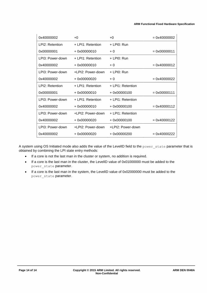
Table 8 demonstrates how the entry methods for the LPI states are combined to produce the correct PSCI power-state parameters:
Table 8 PSCI power_state composition from LPI states
Composite power state
Core
local state
Core
local state
Core
local state
PCI power_state
parameter
LPI2: Retention + LPI0: Run + LPI0: Run
0x00000001 + 0 + 0 = 0x00000001
LPI3: Power-down + LPI0: Run + LPI0: Run
ARM Functional Fixed Hardware Specification
Page 14 of 14 Copyright © 2015 ARM Limited. All rights reserved. ARM DEN 0048A Non-Confidential
0x40000002 +0 +0 = 0x40000002
LPI2: Retention + LPI1: Retention + LPI0: Run
0x00000001 + 0x00000010 + 0 = 0x00000011
LPI3: Power-down + LPI1: Retention + LPI0: Run
0x40000002 + 0x00000010 + 0 = 0x40000012
LPI3: Power-down +LPI2: Power-down + LPI0: Run
0x40000002 + 0x00000020 + 0 = 0x40000022
LPI2: Retention + LPI1: Retention + LPI1: Retention
0x00000001 + 0x00000010 + 0x00000100 = 0x00000111
LPI3: Power-down + LPI1: Retention + LPI1: Retention
0x40000002 + 0x00000010 + 0x00000100 = 0x40000112
LPI3: Power-down +LPI2: Power-down + LPI1: Retention
0x40000002 + 0x00000020 + 0x00000100 = 0x40000122
LPI3: Power-down +LPI2: Power-down +LPI2: Power-down
0x40000002 + 0x00000020 + 0x00000200 = 0x40000222
A system using OS Initiated mode also adds the value of the LevelID field to the power_state parameter that is
obtained by combining the LPI state entry methods:
If a core is not the last man in the cluster or system, no addition is required.
If a core is the last man in the cluster, the LevelID value of 0x01000000 must be added to the
power_state parameter.
If a core is the last man in the system, the LevelID value of 0x02000000 must be added to the
power_state parameter.