Arlington, Virginia - Penn State Engineering€¦ · · 2005-04-05Arlington, Virginia Michael...
32
Inovative option in the design of residential structures Arlington Gateway Hotel Arlington, Virginia M M i i c c h h a a e e l l G G r r a a y y Structural Option Spring 2005 Senior Thesis Architectural Engineering Penn State University
Transcript of Arlington, Virginia - Penn State Engineering€¦ · · 2005-04-05Arlington, Virginia Michael...

Inovative option in the design of residential structures
AArrlliinnggttoonn GGaatteewwaayy HHootteell Arlington, Virginia MMiicchhaaeell GGrraayy Structural Option
Spring 2005 Senior Thesis Architectural Engineering
Penn State University
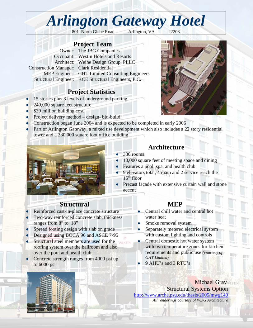
Project Team Owner: The JBG Companies Occupant: Westin Hotels and Resorts Architect: Weihe Design Group, PLLC Construction Manager: Clark Residential MEP Engineer: GHT Limited Consulting Engineers Structural Engineer: KCE Structural Engineers, P.C.
Project Statistics
♦ 15 stories plus 3 levels of underground parking ♦ 240,000 square feet structure ♦ $39 million building cost ♦ Project delivery method – design- bid-build ♦ Construction began June 2004 and is expected to be completed in early 2006 ♦ Part of Arlington Gateway, a mixed use development which also includes a 22 story residential
tower and a 330,000 square foot office building
Architecture ♦ 336 rooms ♦ 10,000 square feet of meeting space and dining ♦ Features a pool, spa, and health club ♦ 9 elevators total, 4 main and 2 service reach the
15th floor ♦ Precast façade with extensive curtain wall and stone
accent
Structural ♦ Reinforced cast-in-place concrete structure ♦ Two-way reinforced concrete slab, thickness
ranges from 8” to 18” ♦ Spread footing design with slab on grade ♦ Designed using BOCA 96 and ASCE 7-95 ♦ Structural steel members are used for the
roofing system over the ballroom and also over the pool and health club
♦ Concrete strength ranges from 4000 psi up to 6000 psi
MEP ♦ Central chill water and central hot
water heat ♦ Smoke removal system ♦ Separately metered electrical system
with custom lighting and controls ♦ Central domestic hot water system
with two temperature zones for kitchen requirements and public use (courtesy of GHT Limited)
♦ 9 AHU’s and 3 RTU’s
Michael Gray
Structural Systems Option http://www.arche.psu.edu/thesis/2005/mwg140
All renderings courtesy of WDG Architecture
Arlington Gateway Hotel 801 North Glebe Road Arlington, VA 22203

Arlington Gateway Hotel Table of Contents
Michael Gray – Structural Option - 1 - Spring 2005 Senior Thesis
Table of Contents
Table of Contents . . . . . . . . . . . . . . . . . . . . . . . . . . . . . . . . . . . . . 1 Executive Summary . . . . . . . . . . . . . . . . . . . . . . . . . . . . . . . . . . . . 2 Introduction . . . . . . . . . . . . . . . . . . . . . . . . . . . . . . . . . . . . . . . . . . 3 General Description . . . . . . . . . . . . . . . . . . . . . . . . . . . . . . . . . . . . 4 Structural Overview . . . . . . . . . . . . . . . . . . . . . . . . . . . . . . . . . . . . 6 Problem Statement . . . . . . . . . . . . . . . . . . . . . . . . . . . . . . . . . . . . 8 Structural Redesign . . . . . . . . . . . . . . . . . . . . . . . . . . . . . . . . . . . . 9 Architectural Impact . . . . . . . . . . . . . . . . . . . . . . . . . . . . . . . . . . . . 25 Construction Management . . . . . . . . . . . . . . . . . . . . . . . . . . . . . . . 26 Final Recommendation . . . . . . . . . . . . . . . . . . . . . . . . . . . . . . . . . 28 Acknowledgements . . . . . . . . . . . . . . . . . . . . . . . . . . . . . . . . . . . . 29 References . . . . . . . . . . . . . . . . . . . . . . . . . . . . . . . . . . . . . . . . . . . 30

Arlington Gateway Hotel Executive Summary
Michael Gray – Structural Option - 2 - Spring 2005 Senior Thesis
Executive Summary The rise in building material and labor costs has led to the growing popularity of hybrid structural systems. Such systems incorporate a steel frame with precast prestressed hollow core plank slabs. Two of these systems were researched for use in redesigning the Arlington Gateway Hotel. 1) Staggered Truss System 2) Girder-Slab System The hotel is a 15 story, 250,000 square foot reinforced cast-in-place concrete structure located in Arlington, Virginia. The best alternative system will be selected for redesign. The design of the new structural system includes three parts. 1) Design of gravity members 2) Design of columns 3) Design of lateral resisting system Once the structural is designed, changes to the architectural systems and Construction Management issues will be discussed. Two architectural systems have been chosen to be researched and designed. 1) Fireproofing 2) In-fill walls Next, an analysis of cost and scheduling of the selected system will be completed. This will show any advantages or disadvantages in the construction of the chosen alternate system. A final recommendation will be made as to whether the selected system is a viable option in mid-rise hotel construction.
Arlington Gateway Hotel Introduction
Michael Gray – Structural Option - 3 - Spring 2005 Senior Thesis
Introduction
The Arlington Gateway Hotel is the third and final phase of the Arlington Gateway complex developed by JBG Companies. The complex is located in the Ballston area of Arlington, Virginia. It was designed for mix use occupancy consisting of a 22 story, 415-unit apartment tower and a 350,000 square foot office building, along with the hotel. Arlington Gateway is located within minutes of Reagan National Airport, a Metro station, and the numerous business centers of Washington, D.C. Designed by Weihe Design Group, PLLC (WDG), the Arlington Gateway Hotel is Northern Virginia’s first Westin Hotel, a 4-star service hotel. The structure is 15 stories tall and totals 250,000 square feet with 335 units. The hotel has many features such as a Starbucks Café, retail outlets, restaurant and lounge, meeting facilities, and a ballroom. Other amenities include an indoor swimming pool, fitness center, and spa. The other key members working on the Arlington Gateway Hotel are Clark Residential, KCE Structural Engineers, and GHT Limited. Clark began construction of the hotel in June 2004 with completion anticipated in early 2006. Clark is serving as the general contractor on all three phases of Arlington Gateway, which is currently the largest commercial construction project in Northern Virginia. KCE Structural Engineers designed the cast-in-place concrete hotel’s structural members. GHT Limited designed the mechanical, electrical, and plumbing systems of the structure. This report is the culmination of a year long thesis, which studied the procedures and analysis of the structural design of the Arlington Gateway Hotel. It includes research on the structural systems of the building and its alternatives and is meant solely as an educational device to gain knowledge on common structural systems in mid-rise residential structures.

Arlington Gateway Hotel General Description
Michael Gray – Structural Option - 4 - Spring 2005 Senior Thesis
General Description Site The Arlington Gateway development is located on North Glebe Road in Arlington, Virginia. Figure 1 is an aerial photo taken before construction began on the three phase project. The site was cleared and excavated to a depth of 35 feet using soldier piles and wood lagging as sheeting and shoring around the perimeter of the site. After construction of the 22 story residential tower (labeled A in Figure 2) and the 13 story office building (labeled B in Figure 2), space was limited for the construction of the Arlington Gateway Hotel (labeled C in Figure 2). One lane of traffic and the sidewalk is closed off for delivery of materials and storage of dumpsters and trailers. Architecture The Arlington Gateway Hotel is a 250,000 square foot structure. The height of the building is 170 feet from the ground level to the top of the mechanical penthouse. There are 335 units in the 15 story building. The break down of each floor total area is shown in the figures on the left. There is also an additional 3 levels of below grade parking beneath the entire Arlington Gateway development. The lowest level of the parking garage is 30 feet below ground level. The exterior of the hotel is composed of non load bearing architectural precast concrete panels with stone accents. The conventional precast cladding totals approximately 65,000 square feet. The panels match that of the residential tower and office building. The roof is comprised of three main sections. There are two lower roofs over the ballroom and pool; comprised of cap sheet, over roofing membrane, over approved substrate, over tapered insulation, over metal decking. The high roof is made up of ballast (stone or concrete), over R-19 roof insulation, over EPDM roofing membrane, over a concrete
Figure 1 – Aerial View Figure 2 – Site Rendering
A
B
C

Arlington Gateway Hotel General Description
Michael Gray – Structural Option - 5 - Spring 2005 Senior Thesis
slab. Partition walls are constructed using 25 gauge metal studs and gypsum wallboard finish. Mechanical The hotel will have central chill and hot water heat. Ventilation throughout the hotel is done by 9 air handling units and 3 roof top units. Air handling units are located on the mezzanine level between the first and second floor to ventilate the lower levels of the hotel. A cooling tower is also located on the roof. Electrical & Lighting The hotel uses a separately metered electrical system throughout the building. Each floor is provided with its own electrical room and panel boxes. Each hotel unit will be wired to a 20 amp breaker. The hotel will have custom lighting and controls. Fire Protection A sprinkler system is used throughout the hotel. Also part of the fire protection is a smoke removal system. There is a fire command center is located in the structure to monitor all systems in case of an emergency. Transportation There are a total of nine elevators in the hotel. Four main elevators are located in the center of the hotel servicing the lobby through the 15th floor. At the eastern end of the structure are 2 service elevators that service the lobby through the 15th floor. There are also 2 elevators from the parking garage beneath the building through to the lobby and one elevator from the lobby through to the third floor, which is located on the western end of the hotel. This elevator services the ballroom and 10,000 square feet of meeting space direct from the main entrance. Telecommunications Each room is outfitted with a high speed internet connection via CAT-V cable, along with the internet service coaxial cable to provide premium cable. The phones located in each room will be able to call down to the service desk as well as make local calls.
Arlington Gateway Hotel Structural Overview
Michael Gray – Structural Option - 6 - Spring 2005 Senior Thesis
Structural Overview
Summary of the Overall Structural System The overall structural system of the building is a reinforced concrete two-way flat plate. The slabs are generally 8 inches thick with #4 reinforcement bars at 12 inches on center, each way. Concrete with a compressive strength of 4000 psi is used in all floor slabs. The building bears on spread footings and continuous wall footings. Column dimensions are generally 32 inches by 32 inches in the lower levels and require 6000 psi concrete. On the second through eighth floor the columns require 5000 psi concrete, while 4000 psi concrete is used on the remaining floors. The columns on the upper floors reduce in size to 16 inches by 32 inches. Reinforcing steel is to be grade 60, except for column ties and beam stirrups which are to be a minimum of grade 40. Foundation The foundation of the building bears on decomposed rock. The structure uses spread footings that were designed for two different bearing conditions, 40 ksf and 80 ksf. The soil bearing conditions needs to be checked by a geotechnical engineer for each footing to determine which design to use. The footings are to use 4000 psi normal weight concrete. For the design of foundation walls, an equivalent fluid pressure of 60 pcf should be used above the water table and an additional 62.5 pcf below the water table. Ground water was found approximately 15 to 20 feet below the existing ground surface. Codes The hotel’s structural members were designed using ACI 318-97 and AISC – 8th Edition. ACI 318-97 was used to design the minimum requirements of the concrete members along with calculating loading using the equation of 1.4D + 1.7L for factored loads. AISC – 8th Edition is the steel manual for Allowable Stress Design (ASD), this was used for the design of the steel members in the pool and ballroom areas. Loading on the building was determined using BOCA 96 and ASCE 7-95. These codes were used to define the loading on the lateral systems due to wind and seismic forces. Also they define the minimum required gravity loads, such as live loads on the structure and material dead loads. The live loads include snow loading and loading due to objects that can be moved such as people and furniture. Lateral System The lateral load resisting system uses moment frames to counter the forces of wind. Reinforced concrete structures naturally lend themselves to the use of moment frames due to the monolithic pouring of the concrete and the various structural members are reinforced as a unit. Each beam to column connection in the structure acts as a moment connection.

Arlington Gateway Hotel Structural Overview
Michael Gray – Structural Option - 7 - Spring 2005 Senior Thesis
Summary of Loads The building’s roof was designed using a live load of 16 psf and the penthouse floor was designed for 150 psf. Typical floors were designed using a live load of 40 psf plus 15 psf for partitions. Corridors were designed using a live load of 70 psf. The 15 psf load for partitions is usually taken as dead load, but in this case was used as live load for possible future remodeling of the floors. This would change locations of walls and create a new distribution of loads. Other live loads include 100 psf for the first floor and stairs, and 250 psf for the loading dock.
The accumulation of dead loads includes the weight of the building materials and miscellaneous mechanical, electrical, and plumbing (MEP) fixtures. The 8 inch flat slab has a dead load of 100 psf plus 10 psf for MEP and other miscellaneous loads being applied to each floor. The total loading on each floor is shown in the table. This analysis uses a live load of only 40 psf, as the corridors make up a small percentage of floor area so they were not included.
Miscellaneous Loading and Conditions Since the building has a cast-in-place concrete roof slab, uplift due to wind is not a major factor due to the weight of the slab. The slabs of the below grade parking area aid in retaining the lateral earth pressure applied to the basement walls.
Level Total Live Load (psf)
Total Dead Load (psf)
Dead Weight
(lbs)
Live Weight
(lbs)
Factored Total
Weight (lbs) 15 (roof) 170 110.0 1742510 2692970 6399764
14 40 125.0 1980125 633640 3389974 13 40 125.0 1980125 633640 3389974 12 40 125.0 1980125 633640 3389974 11 40 125.0 1980125 633640 3389974 10 40 125.0 1980125 633640 3389974 9 40 125.0 1980125 633640 3389974 8 40 125.0 1980125 633640 3389974 7 40 125.0 1980125 633640 3389974 6 40 125.0 1980125 633640 3389974 5 40 125.0 1980125 633640 3389974 4 40 125.0 1980125 633640 3389974 3 40 125.0 1980125 633640 3389974 2 40 125.0 1980125 633640 3389974
1 40 125.0 1980125 633640 3389974
SUM 29464260 11563930 53859400

Arlington Gateway Hotel Problem Statement
Michael Gray – Structural Option - 8 - Spring 2005 Senior Thesis
Problem Statement The major disadvantage to a cast-in-place concrete structure is the amount of labor that goes into construction. The building of formwork, placing of rebar, and finally pouring of concrete are long and expensive processes. Quicker construction of a structure such as a hotel can lead to it being open for business earlier; thus, bringing in revenue sooner for the owner. The old cliché, time is money, is ideal for any structure, especially a hotel. An investigation into an alternate structural system that will speed up the erection process is needed. This system needs to be cost effective as well as quicker to construct and have most, if not all, of the advantages a cast-in-place concrete system provides. Solution Overview Structural Redesign In investigating the different structural systems of mid-rise hotel structures, cast-place-concrete, especially a flat-slab design was the most popular choice. This type of construction provides a finished floor and ceiling with very shallow floor-to-floor heights. This reduces the amount of exterior façade needed, while also reducing the area and lateral loads on the structure. It was difficult to find a viable alternative to this type of construction and still keep the current architectural layout without many changes. There are several structural options for a mid- to high-rise hotel besides cast-in-place concrete. In keeping with low floor-to-floor heights, the selection was narrowed down to two structural systems for this study. 1) The Staggered Truss System 2) The Girder-Slab System Each of these systems will be researched with the advantages and disadvantages weighed to select the best possible option. Once selected, the best optional structural system will be used in the redesign of the hotel. Architectural Impact Changing the structural system will have an impact on the overall architectural design of the hotel. Even though part of the structural redesign is to minimize changes to the floor plan, changes in column size and slight changes to location will affect some hotel units. Also, a look at the type and design of infill walls that are required due to the changes to the structural systems will need to be done. Construction Management The major reason for looking into an alternative structural system is to try and reduce the costs and the length of time it takes to complete construction of the hotels structural system. A construction schedule and an estimate need to be made to compare the new structural system with the old. Also, the new structural system needs to be feasible due to site restrictions and constraints on construction.

Arlington Gateway Hotel Structural Redesign
Michael Gray – Structural Option - 9 - Spring 2005 Senior Thesis
Structural Redesign
Alternative Systems Overview Staggered Truss
The Staggered Truss System is once again growing in popularity amongst designers of residential structures. This is due to several key features that have great benefits that make it ideal for these types of buildings. This system uses a combination of steel members and precast hollow core plank to make up the structural system. The system gets its name from the use of trusses that are staggered from floor-to-floor that give
large open areas the full width of the building. Having the trusses staggered reduces the weight of the frame, which reduces seismic loads and foundation costs. With fewer structural members the structure can be erected and completed faster with fewer shop drawings. The story-high trusses have the ability to span the width of the building allowing for fewer columns and greater architectural freedom. These deep trusses minimize deflection and provide greater stiffness to the overall structure. The use of vierendeel openings in the trusses allow for corridors. The flooring system in a Staggered Truss uses precast plank. These planks are precast and prestressed with hollow cores. Hollow core plank come in several different sizes, but are generally 8 inches thick and 4 feet wide. They are able to span long distances of about 30 feet because they are prestressed and have hollow cores that reduce their weight. Using precast plank provides a semi-finished floor and ceiling which lowers cost and speeds up erection time. The Girder-Slab System
The Girder-Slab System, also known as a flex frame system, is relatively new and innovative. It combines a steel frame with precast planks. This system has been around for only about 7 years and has been utilized on 15 residential structures. The Girder-Slab System is innovative because it uses interior girders that are known as open-web dissymmetric beams or D-Beams. The D-Beam starts out as a Grade 50 standard wide flange section that is
split by castellation to produce two D-Beam Girders without waste. A flat bar is placed as the top flange. The inverted ‘T’ shape of the beam allows for easy placement of
Arlington Gateway Hotel Structural Redesign
Michael Gray – Structural Option - 10 - Spring 2005 Senior Thesis
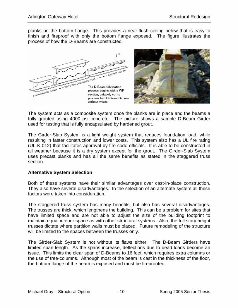
planks on the bottom flange. This provides a near-flush ceiling below that is easy to finish and fireproof with only the bottom flange exposed. The figure illustrates the process of how the D-Beams are constructed.
The system acts as a composite system once the planks are in place and the beams a fully grouted using 4000 psi concrete. The picture shows a sample D-Beam Girder used for testing that is fully encapsulated by hardened grout. The Girder-Slab System is a light weight system that reduces foundation load, while resulting in faster construction and lower costs. This system also has a UL fire rating (UL K 012) that facilitates approval by fire code officials. It is able to be constructed in all weather because it is a dry system except for the grout. The Girder-Slab System uses precast planks and has all the same benefits as stated in the staggered truss section. Alternative System Selection Both of these systems have their similar advantages over cast-in-place construction. They also have several disadvantages. In the selection of an alternate system all these factors were taken into consideration. The staggered truss system has many benefits, but also has several disadvantages. The trusses are thick, which lengthens the building. This can be a problem for sites that have limited space and are not able to adjust the size of the building footprint to maintain equal interior space as with other structural systems. Also, the full story height trusses dictate where partition walls must be placed. Future remodeling of the structure will be limited to the spaces between the trusses only. The Girder-Slab System is not without its flaws either. The D-Beam Girders have limited span length. As the spans increase, deflections due to dead loads become an issue. This limits the clear span of D-Beams to 16 feet, which requires extra columns or the use of tree-columns. Although most of the beam is cast in the thickness of the floor, the bottom flange of the beam is exposed and must be fireproofed.

Arlington Gateway Hotel Structural Redesign
Michael Gray – Structural Option - 11 - Spring 2005 Senior Thesis
A table was created to put a numerical value on each system to aid in selection. The table has a scale of 1-5 with 5 being the highest rating.
Staggered Truss Girder-Slab Flat-Slab
Fire Resistance 3 4 5
Light Weight 5 5 2
Speed of Construction 5 4 3
Adaptable to current layout 3 4 5
16 17 15
The Girder-Slab System will be selected and designed in accordance with current building codes and minimal impact on the current architectural layout of the Arlington Gateway Hotel. This system was selected because it will work best with the current layout of the hotel and is more adaptable to possible future remodeling plans. Procedure for Redesign Several things need to be accomplished to redesign the structural system of the hotel using the Girder-Slab System. 1) Gravity and lateral loads for the new structure need to be calculated. 2) Design the floor system. 3) Design the columns with respect to building loads. 4) Design the braced frame lateral system. Each of these steps will be carried out in upcoming sections to culminate in a complete design of an alternative structural system for the hotel. Summary of Design Loads The first step in designing a structure is to determine the design loads. Loading on the proposed structure was determined using IBC 2003 and ASCE 7-02, the latest building codes. These codes were used to define the loading on the lateral systems due to wind and seismic forces. Also they define the minimum required gravity loads, such as live loads. The live loads include snow loading and loading due to objects that can be moved such as people and furniture.

Arlington Gateway Hotel Structural Redesign
Michael Gray – Structural Option - 12 - Spring 2005 Senior Thesis
Gravity Loads ASCE 7-02 was used to define the minimum required design loads for the hotel, which is included in residential structures. These loads include live loads and dead loads. Design live loads are broken into three areas: 1) Corridors – 100 psf 2) Private Rooms – 40 psf 3) Mechanical Penthouse/Roof – 100 psf An additional live load of 15 psf was added for the weight of partitions. Partitions were included in the live load of the structure since the position of the walls may change with future renovations. They do not have an impact on the dead load deflection of the members as they will not be installed prior to the beams becoming composite. This will be explained in more detail in the Design of Floor Members Section. A load of 16 psf was found through snow load calculations to be applied to the roof surfaces. There is a potential for accumulation of drifting snow, which should be checked. To find the dead load of the structure, the weight of the precast prestressed hollow core plank was found. Plank with a thickness of 8 inches is used in the design of the structure. This plank has a weight of 56 psf. An additional 4 psf was applied to the dead load due to leveling grout that will be placed over top of the plank. The table below shows total loading on each floor of the Girder-Slab system. The corridor live loads were not included in the table because they comprise a very small section of the overall floor plan.
Level Total Live Load (psf)
Total Dead Load (psf)
Dead Weight (lbs)
Live Weight (lbs)
Factored Total Weight (lbs)
15(roof) 116 80.0 1267280 1837556 4460826 14 55 60.0 950460 871255 2534560 13 55 60.0 950460 871255 2534560 12 55 60.0 950460 871255 2534560 11 55 60.0 950460 871255 2534560 10 55 60.0 950460 871255 2534560 9 55 60.0 950460 871255 2534560 8 55 60.0 950460 871255 2534560 7 55 60.0 950460 871255 2534560 6 55 60.0 950460 871255 2534560 5 55 60.0 950460 871255 2534560 4 55 60.0 950460 871255 2534560 3 55 60.0 950460 871255 2534560 2 55 60.0 1010460 926255 2694560
1 55 60.0 1010460 926255 2694560
SUM 14693720 14145126 40264665.6

Arlington Gateway Hotel Structural Redesign
Michael Gray – Structural Option - 13 - Spring 2005 Senior Thesis
This system reduces the dead weight of the structure by nearly 7,400 tons compared to the original cast-in-place structural system.
Dead Weight (tons)
Girder Slab System 7347
Cast-In-Place System 14732
7385
Lateral Loads The calculation of lateral loads is dependant upon the type of opposing system used. The redesign uses braced frames, which result in different loading conditions than the existing structures moment frames. Use of steel and precast plank reduces the overall structural weight of the building as shown in the previous section. A lighter framed building resists lateral loads different and thus has differently design loads than a heavier structure. Wind Due to the irregular shape of the building, the shape was taken as a rectangle equal to that of the floor area of the upper most floors to calculate the wind load. The dimensions of the rectangle are 73 feet in the North-South direction and 217 feet in the East-West direction. The following are the wind pressure diagrams in each direction.

Arlington Gateway Hotel Structural Redesign
Michael Gray – Structural Option - 14 - Spring 2005 Senior Thesis
Comparing a braced steel framed structure with a cast-in-place concrete moment frame structure, the steel frame has similar wind pressure and resulting load to the concrete frame. Wind loading diagrams are provided below for the steel frame, which show the total force exerted on each floor. An un-factored base shear in the N-S direction of 668 kips was calculated, while it 560 kips in the E-W direction. Using the appropriate factor of 1.6 times the force due to wind, a base shear of 1070 kips was in the N-S direction and 894 kips in the E-W direction was calculated. Seismic The seismic loads were calculated using site classification C and use group III. The result of the calculations is summarized in the Seismic Loading Diagram to the right. The resultant base shear is 746 kips. Seismic loads use a factor of 1.0 in design which results in the same shear force. The lighter steel structure has smaller seismic loads when compared to the heavier concrete structure. The base shear of the current concrete structure was calculated as 896 kips. This results in a 150 kip difference between the two systems. Conclusion The load case that provides the highest resulting lateral force on the structure after being factored needs to be selected. From the information provided in the Wind and Seismic sections, the force due to wind creates the most

Arlington Gateway Hotel Structural Redesign
Michael Gray – Structural Option - 15 - Spring 2005 Senior Thesis
force acting on the base of the structure. Wind forces will be used in the design of the lateral system. Design of Floor Members To begin design of the floor system, the location of D-Beams needed to be determined. They are designed as a composite beam because once the hollow core plank is set on the bottom flange; the beam is then fully encased in concrete. The concrete gives the beam the added strength to carry the live load of the structure. The major issue with the D-Beam is the resultant dead load deflection being greater than l/240 due to the weight of the precast plank. This limits the span to around 16 feet when the plank is spanning 28 feet. There are several solutions to the dead load deflection problem. It is possible to have the D-Beam constructed with a positive camber, where once the planks are set into place and the beam deflects, it deflects to a level condition. Another solution is to shore the pre-composite assemble until the grout is in place and reaches its required strength. Last but not least, tree-columns can be used. Tree-columns use WT shapes up to 2 feet that attached to the columns. The D-Beam is then attached to the ends of the WT shapes and this increases the available clear span. The tree-column will be discussed in more depth in the Design of Columns Section. The steel columns were able to be located in the same place as the cast-in-place concrete columns of the existing structure. The D-Beams were then positioned to span the shortest distance between the columns, which equaled a length of 17 feet. The planks span 27 feet perpendicular to the beams. Design of the D-Beams was done under AISC Allowable Stress Design. Using the gravity loading discussed in the previous section, each beam was checked for Initial/Precomposite condition, live load deflection, stress in the bottom flange, and shear using the D-Beam properties provided by Girder-Slab. A spread sheet similar to the one on the next page was created for each of the D-Beam members to check all of these conditions. There are four members that were designed for use with an 8 inch slab by Girder-Slab. 1) DB 8x35 2) DB 8x37 3) DB 8x40 4) DB 8x42 Live load reduction was applied where the transposed area of the member was greater than 400 square feet, according to ASCE 7-02. The following structural plan shows the layout of precast plank and the sizes of beams used in the floor.

Arlington Gateway Hotel Structural Redesign
Michael Gray – Structural Option - 16 - Spring 2005 Senior Thesis
Engineer: Job: DB 8-40
Beam #: B-1
Building Properties
Dead Loads (psf) 60 Live Loads (psf) 55 918 > 400 Ok?
Clear Span (ft) 17 Live Load Reduction 40.98
Tributary Span (ft) 27
f'c = 4000
Beam Properties Steel Section Transformed Section
IS = 122 It = 289 St = 26.5 St = 67.2 Sb = 36.1 Sb = 67.9
Mscap = 66 b = 3.5 tw = 0.340
Allowable Live Load
Deflection (L/360) 0.57
Initial/Precomposite Condition MDL (ft-k) 58.5225 < 66 OK?
Dead Load Deflection 0.86
Total Load - Composite
MSUP = 40.0 MTL = 98.5
SREQ = 39.4 < 67.2 OK? Live Load Deflection 0.25 < 0.57 OK?
Compressive Stress on Concrete
N = 8.04 STC = 540.6
fc = 0.89 < 1.8 OK?
Bottom Flange Tension Stress (Total Load) fb = 26.5
Fb = 45 > 26.5 OK?
Shear Total load = 100.98
w = 2.73 R = 23.17 fv = 19.47
Fv = 20 > 19.47 OK?

Arlington Gateway Hotel Structural Redesign
Michael Gray – Structural Option - 17 - Spring 2005 Senior Thesis

Arlington Gateway Hotel Structural Redesign
Michael Gray – Structural Option - 18 - Spring 2005 Senior Thesis
Structural Details The following details are typical sections from the Girder-Slab Design Guide v2.1. They are important details to understanding how the system works and are relevant for this design.

Arlington Gateway Hotel Structural Redesign
Michael Gray – Structural Option - 19 - Spring 2005 Senior Thesis

Arlington Gateway Hotel Structural Redesign
Michael Gray – Structural Option - 20 - Spring 2005 Senior Thesis
Design of Columns Standard Design Steel columns for the system were designed using standard 50 ksi wide flange members. Columns are assumed to take only axial loads as the lateral loads will be distributed through the floor system and resisted by the proposed braced frames. The table on the right is the column schedule for column K8 on the previous structural plan. The column was designed to span three floors with the column splices centered between floor slabs. The table shows the load at each floor according to Load and Resistance Factor Design, using a factor of 1.2 times the dead load plus 1.6 times the live load. The loads on the column are stated in the Summary of Design Loads Section. For this column, live load reduction was used on each floor except the roof. Live load was reduced up to a maximum of 40 percent as allowed by ASCE 7-02. Using the axial load on the column and the unbraced height, the column was sized using the design table in the AISC Manual of Steel Construction – LRFD Third Edition.
Floor Height
129
15 10'
W12
x40
193
14 9'
W12
x40
252
13 9'
W12
x40
308
12 9'
W12
x50
Column Splice @ Mid-Height
363 11 9'
W12
x50
417
10 9'
W12
x50
471
9 9'
W12
x58
Column Splice @ Mid-Height
525 8 9'
W12
x58
579
7 9' W
12x5
8
633
6 9'
W12
x72
Column Splice @ Mid-Height
687 5 9'
W12
x72
741
4 9'
W12
x72
795
3 9'
W12
x106
Column Splice @ Mid-Height
849 2 16'
W12
x106
903
1 16'
W12
x106

Arlington Gateway Hotel Structural Redesign
Michael Gray – Structural Option - 21 - Spring 2005 Senior Thesis
Alternative Design The use of tree-columns can help the D-Beam system meet the dead load deflection requirements for longer spans. The figure below is a section detail of a common tree column connection. In this case, a wide flange (WF) column is used and WT beam with
a flat bar is welded to the column. These act as branches of the tree to support the attached D-Beam. A two foot section of WT + FB can be used on either side of the D-Beam to allow for a clear span of 20 feet while minimizing deflection. The branches will be fully welded to the column creating a moment in the column due to gravity loads. The column will then need to be designed for a combination of axial load and moment.
Alternative Column Details The detail below shows all of the possible D-Beam connections to a wide flange column. Similarly, HSS shapes can be used in place of the wide flange columns.

Arlington Gateway Hotel Structural Redesign
Michael Gray – Structural Option - 22 - Spring 2005 Senior Thesis
Design of the Lateral System Braced frames were selected for use in the redesign of the Arlington Gateway Hotel. These were selected because they are often the most economical method of resisting lateral loads on a mid-rise structure. The other option would be to use moment frames that tend to be more costly due to detailed and complicated connections. The braced frames will be designed using the wind loads, as they created more base shear than the seismic loads by code. There appears to be no standard design of braced frames, which allow for creative and innovative solutions by an engineer. K-Frame bracing was designed for this structure. The frames were designed with the apex of the braces pointing up. The apex pointing up results in less story deflection than if the apex was pointing down when compared to a system with the same area of steel. The wind load on each floor was used in the design of the braced frames. The required area of steel was calculated for each member. The following tables show the results of these calculations. The assumption was that one frame would resist the entire lateral load in each direction to find the area of steel required.
K-Frame Member Design N-S Direction
Floor Load @ Floor (kip)
Column Area (in2)
Girder Area (in2)
Brace Area (in2)
Floor Deflection (in.)
Total Deflection (in.)
15 24 0.0 0.0 9.8 0.366 4.227 14 47 7.4 10.9 15.8 0.336 3.861 13 46 19.8 14.0 20.4 0.336 3.524 12 46 35.7 16.5 24.0 0.331 3.188 11 45 54.3 18.6 27.1 0.324 2.857 10 45 75.4 20.5 29.9 0.314 2.533 9 44 98.5 22.2 32.4 0.301 2.220 8 43 123.6 23.8 34.7 0.287 1.918 7 42 150.4 25.2 36.8 0.271 1.631 6 42 178.7 26.6 38.8 0.254 1.360 5 41 208.6 27.8 40.6 0.235 1.107 4 40 239.8 29.0 42.3 0.214 0.872 3 39 272.3 30.1 43.9 0.193 0.658 2 69 306.0 31.9 68.0 0.270 0.465 1 57 353.5 33.4 71.1 0.195 0.195

Arlington Gateway Hotel Structural Redesign
Michael Gray – Structural Option - 23 - Spring 2005 Senior Thesis
K-Frame Member Design E-W Direction
Floor Load @ Floor (kip)
Column Area (in2)
Girder Area (in2)
Brace Area (in2)
Floor Deflection (in.)
Total Deflection (in.)
15 7.9 0.0 0.0 9.9 0.279 3.280 14 15.8 6.8 5.7 11.8 0.252 3.001 13 15.5 15.1 6.8 13.9 0.249 2.749 12 15.5 24.9 7.7 15.8 0.245 2.499 11 15.1 36.0 8.4 17.4 0.238 2.255 10 15.1 48.3 9.2 18.9 0.230 2.016 9 14.8 61.5 9.8 20.2 0.221 1.786 8 14.5 75.8 10.4 21.4 0.211 1.564 7 14.3 90.8 11.0 22.6 0.200 1.353 6 14.0 106.8 11.5 23.7 0.188 1.153 5 13.7 123.4 12.0 24.7 0.175 0.965 4 13.4 140.8 12.4 25.6 0.162 0.789 3 13.1 158.8 12.9 26.5 0.147 0.627 2 23.2 177.4 13.6 45.7 0.264 0.480 1 19.0 203.7 14.2 47.6 0.216 0.216
The frames were designed for a deflection ratio of 0.0025 or L/400 under wind service loads. This deflection ratio was used to reduce the effect of drift on the precast cladding. L/400 is a reasonable deflection ratio to prevent damage to the exterior cladding system. The total required area of steel for each member is then divided by the number of braced frames being used. This gives the required area of steel for each individual frame. There are 5 proposed frames in the N-S direction, giving a required column area for each frame of 70 square inches per 2 columns. A W12x120 column would be required on the first floor. The three frames in the E-W direction require columns areas of 68 square inches per 2 columns. These also require W12x120 columns. The area calculated considers only lateral loads and if there is additional loading on the member, the member should be sized due to the additional load cases. The calculated total deflection on the frames, shown in the tables, is only for use with the member areas calculated. In other words, deflection on the upper floors will decrease when the members are checked for axial loads. The axial loading will control column sizing; therefore, a column with a larger area will be required while reducing story drift. These tables and results should only be used for schematic design of the frames to find an initial starting point with use in a computer analysis program. A structural analysis program will be able to calculate for the combination of

Arlington Gateway Hotel Structural Redesign
Michael Gray – Structural Option - 24 - Spring 2005 Senior Thesis
axial load on the columns due to the building’s gravity loads and lateral loads and any possible second order effects. Overturning Overturning needs to be checked on the frames. By inspection it is visible that there will be issues with overturning. With the current placement of frames, there is not much building weight being applied to the frames. The N-S frames have a resultant overturning moment of 10914 foot kips. This creates an uplift on the 17 foot frame of 642 kips. An example of this is at the North-East elevator shaft where there is only a total of 39 kips of dead weight on the frame to resist uplift. There have been no proposed changes to the 3 levels of parking garage below the structure and all assumptions were based on the steel frame being attached to the current cast-in-place system or the use of a precast system. The weight of the garage will likely not be enough to resist the overturning force so there will be a need of caissons or piles.

Arlington Gateway Hotel Architectural Impact
Michael Gray – Structural Option - 25 - Spring 2005 Senior Thesis
Architectural Impact
Two architectural systems have been chosen to be researched and designed. The use of a steel structural system requires an investigation into fire protection to meet codes. Secondly, in-fill walls such as elevator mechanical room walls and mechanical, electrical, plumbing chases will be explored. Fireproofing One drawback a steel structure has over a concrete structure is the need for additional actions to be taken to meet fire regulations. Exposed steel alone will not meet these standards. One option is to use a spray applied fire resistive material. The columns and the exposed bottom flanges of the D-Beam need to be coated with the fire resistive material to a final thickness of 3/8 of an inch for a 2-hour fire rating. Only the bottom flange of the D-Beam needs application of the fire resistive coating because the rest of the member is cast in concrete. The 8 inches of concrete provide the 2-hour fire rating needed. Another option is the use of fire rated gypsum wall board to enclose the exposed steel. This can be used to encase the bottom flange of the D-Beam, while providing a desirable architectural look. This provides a thin bulkhead around the beam. This is constructed by using 25 gauge metal that is shot to the beam using powder actuated pins. Once attached, 5/8 inch thick gypsum wall board is screwed to the metal and finished using paper tape and joint compound. In-Fill Wall In-fill walls around chases and elevator mechanical room and shaft were researched. Concrete masonry units (CMU) are commonly used around elevator shafts and mechanical rooms on buildings up to 6 stories. In buildings taller than this, shaft walls are constructed using metal CH-Studs and gypsum board. The interior of the shaft is lined with 1 inch thick gypsum shaft-liner board. The exterior is finished with either one or two layers of 5/8 inch gypsum wall board. The exterior layer of board is then paper taped and finished using joint compound.
Arlington Gateway Hotel Construction Management
Michael Gray – Structural Option - 26 - Spring 2005 Senior Thesis
Construction Management
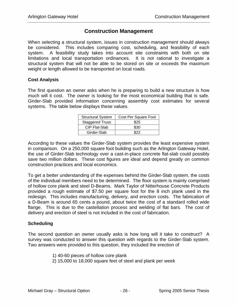
When selecting a structural system, issues in construction management should always be considered. This includes comparing cost, scheduling, and feasibility of each system. A feasibility study takes into account site constraints with both on site limitations and local transportation ordinances. It is not rational to investigate a structural system that will not be able to be stored on site or exceeds the maximum weight or length allowed to be transported on local roads. Cost Analysis The first question an owner asks when he is preparing to build a new structure is how much will it cost. The owner is looking for the most economical building that is safe. Girder-Slab provided information concerning assembly cost estimates for several systems. The table below displays these values.
Structural System Cost Per Square Foot Staggered Truss $25
CIP Flat-Slab $30 Girder-Slab $22
According to these values the Girder-Slab system provides the least expensive system in comparison. On a 250,000 square foot building such as the Arlington Gateway Hotel, the use of Girder-Slab technology over a cast-in-place concrete flat-slab could possibly save two million dollars. These cost figures are ideal and depend greatly on common construction practices and local economics. To get a better understanding of the expenses behind the Girder-Slab system, the costs of the individual members need to be determined. The floor system is mainly comprised of hollow core plank and steel D-Beams. Mark Taylor of Nitterhouse Concrete Products provided a rough estimate of $7.50 per square foot for the 8 inch plank used in the redesign. This includes manufacturing, delivery, and erection costs. The fabrication of a D-Beam is around 65 cents a pound, about twice the cost of a standard rolled wide flange. This is due to the castellation process and welding of flat bars. The cost of delivery and erection of steel is not included in the cost of fabrication. Scheduling The second question an owner usually asks is how long will it take to construct? A survey was conducted to answer this question with regards to the Girder-Slab system. Two answers were provided to this question, they included the erection of 1) 40-60 pieces of hollow core plank 2) 15,000 to 18,000 square feet of steel and plank per week

Arlington Gateway Hotel Construction Management
Michael Gray – Structural Option - 27 - Spring 2005 Senior Thesis
When analyzed these two values yield similar results. Each floor of the hotel is roughly 16,000 square feet, which should take 1 week to construct. The whole structural system should be finished within 16 weeks, which would be 10 weeks faster than the current construction schedule on the hotel. The plank and steel are erected at the same time. Once the plank and steel are set in place, the beams can then be grouted. For safety concerns, there needs to be two floors of separation between where planks are being set and workers working. Conclusions An initial look into the cost and scheduling benefits of the Girder-Slab system provide positive results. In comparison, it is less expensive and faster to construct than conventional cast-in-place structure.

Arlington Gateway Hotel Final Recommendation
Michael Gray – Structural Option - 28 - Spring 2005 Senior Thesis
Final Recommendation
The use of hybrid structural systems has become increasingly popular over the past few years. They require less labor and are generally constructed faster than more labor intensive systems. The Girder-Slab system is an innovative use of steel in a system that rivals cast-in-place (CIP) systems. This report has proved that it is possible to construct a hotel using this system and it does in fact have many benefits over CIP systems. It is not without its limitations as spans between columns are limited due to dead load deflections. In conclusion, the Girder-Slab system is definitely a viable option in the construction of mid-rise structures. It will continue to gain popularity and use in varying projects across the country. The D-Beams can be constructed by many different steel fabricators and is not a proprietary system.

Arlington Gateway Hotel Acknowledgements
Michael Gray – Structural Option - 29 - Spring 2005 Senior Thesis
Acknowledgements
I would like to thank the following people for their help and throughout the year. Owner representative from JBG Corporation Michael Kearney Industry Sponsors Durwood Dixon – WDG Architecture Allen Kilscheimer – KCE Structural Industry Contacts John Cross – AISC Charlie Carter – AISC Mark Tayler – Nitterhouse Concrete Products Daniel Fisher – Girder-Slab Thesis Advisor Linda Hanagan Thesis Professors Kevin Parfitt Jonathan Dougherty I would also like to thank my family, because without them this would not have been made possible. A special thanks goes to my girlfriend whose support has inspired to me to strive to do my best.

Arlington Gateway Hotel References
Michael Gray – Structural Option - 30 - Spring 2005 Senior Thesis
References Girder-Slab Composite Steel and Precast System Coordinated Construction, Cross, John; <http://www.girder-slab.com/Modern_ Steel_Construction_July_2003.pdf > Girder-Slab Design Guide v1.2, Girder-Slab Technologies, LLC., <http://www.girder-slab.com> Steel Construction AISC Manual of Steel Construction – Load and Resistance Factor Design, Third Edition Design Guide 5 – Low- and Medium- Rise Buildings, Allison, Horatio, 2003 Structural Steel Framing Solutions for Multi-Story Residential Buildings, <http://www.aisc.org/Content/ContentGroups/Documents/Marketing2/287_MSR_brochure.pdf>
Photos and Renderings provided by WDG Architecture