ARL-TR-69- 11This report may be reproduced to satisfy needs of L.S. Government ... one-half of a...
23
ARL-TR-69- 11 0 UHF STIMULATION SYSTEM Jose M. R. Delgado, M.D. Gerhard Weiss, B.E.E. Yale University School of Medicine October 1969 Tdocument has been approved for public release and sale] its distribution is unlimited. J 6571st Aeromedical Research Laboratory Aerospace Medical Division Air Force Systems Command Holloman Air Force Base, New Mexico .... .' i 1-
Transcript of ARL-TR-69- 11This report may be reproduced to satisfy needs of L.S. Government ... one-half of a...
ARL-TR-69- 11
0
UHF STIMULATION SYSTEM
Jose M. R. Delgado, M.D.Gerhard Weiss, B.E.E.
Yale University School of Medicine
October 1969
Tdocument has been approved for public release and sale]its distribution is unlimited. J
6571st Aeromedical Research LaboratoryAerospace Medical Division
Air Force Systems CommandHolloman Air Force Base, New Mexico
.... .' i
1-

srrTi WHITE SECTIONDec #OFF SECTION [M AKNOUNC;E1[
.' ...........
O;,TR'IUTI' N MUnfl1tamm s used in this study were handled in accordance with the
01si. All 1cefA Laboratory Animal Facilities and Care" as promulgated/ by te Nat onal Academy of Sciences - National Research Council.
This report may be reproduced to satisfy needs of L.S. Governmentagencies. No other reproduction is authorized except with permissionof the 6571st Aeromedical Research Laboratory, Holloman AFB, NMex.
This report is made available for study with the understanding thatproprietary interests in and relating thereto will not be impaired. In
case of apparent ccrnflict or any other questions between the Govern-ment's rights and those of otheis, notify the Judge Advocate, AirForce Systems Command, Andrews Air Force Base, Washington, D.C.
Do not return this copy. Retain or destroy.

UHF STIMULATION SYSTEM
Jose M. R. Delgad., M.D.Gerhard Weiss, B.E.E.
YaLe University School of Medicine
This document has been approved for public release and sale;its distribution is unlimited.
J_
FOREWORD
This research was conducted by the Yale University School of Medicine'.nder Contract No. F29600-67-C-0058 from I July to 31 December 1968.The contract was monitored by Captain Jan D. Wallace, Bio EffectsDivision, 6571st Aeromedical Research Laboratory under project andtask number 6892/02.
The views expressed herein are those of the author and do notnecessarily reflect the views of the U. S. Air Force or the Departmentof Defense.
This technical report has beer, reviewed and approved for publication.
ROBERT G. McIVER, Colonel, USAF, MC
Commander
ii

ABSTRACT
A UHF remote stimulation system working in the 915 MHz band isdescribed, which generates current pulses in three stimulation chan-nels. The amplitude, duration, repetition rate and channel can becontrolled from a remotely located control panel. This system hasbeen installed at Holloman Air Force Base, New Mexico, to stimulatethe brain of free ranging chimpanzees and study the induced modifi-cations on individual and social behavior.
4
I -
* C
I'

INTRODUCTION
Remote controlled stimulation of the brain based on RF transmissionin the 100 MHz band has been used in our laboratory for several years(Delgado, et al 19691).
in some locations, however, restrictions imposed on the trans-mitting power make convenient the use of less crowded bands of frequencyand the present report describes the system that we have developed forbrain stimulation in free ranging chimpanzees, using a carrier frequencyof 915 MHz.
Figure I indicates the signal flow in the system. The signalsdetermining channel, intensity, duration and repetition rate originate inthe control circuit section (1). The output of the control circuit is a lowpower pulse train which controls the output of the gated power supply (2)and, therefore, the power to the UHF transmitter (3). Buiss of radiofrequency at 915 MHz are generated by the transmitter acco:_ding to thesignals from the control circuit section (1) and radiated by the antenna (4).This equipment is stationary and located outside the animal compound orcage.
The instruments carried by the animal consist of the 915 MHz to100 MHz down converter (5) and the stimulator receiver (6) connected tothe converter. The receiver demodulates the 100 MHz signal from theconverter and generates the stimulation pulses at the appropriate channelas directed by the modulating s gnals from the control circuit section (1).
SUMviMARY
A U1IF remote stimulation system working in the 915 MHz band isdescribed, which generates current pulses in three stimulation channels.The amplitude, duration, repetition rate and channel can be controlledfrom a remotely located control panel. This system has been installed atHollornan Air Force Base, New Mexico, to stimulate the brain of freeranging chimpanzees and study the induced modifications on individualand social behavior.
Ijose M. R. Delgado, M.D., Ronald J. Bradley, Ph. D., Victor S. Jo-nston,Ph.D., Gerhard Weiss, B.E.E. aid Jan D. Wallace, M.D. "Implantation ofMultilead Electrode Assemblies ani Radio Stimulation of the Bra~n inChimpanzees." 6571st Aerornedica] Research Laboratory Techihicai Report,ARL-TR-69-2.

Filli
1.ANTENNA 4 915 -100 MHz5
CONVERTOR
UHF13
TRANSMITTER I
6 STIMULATOR
GA TED
POWER 2
SUPPLY
_____TO
ELECTRODESCONTROL
CIRCUITS
Figure 1. UHF Stimulator System

CIRCUIT DESCRIPTION
A. Control Circuits
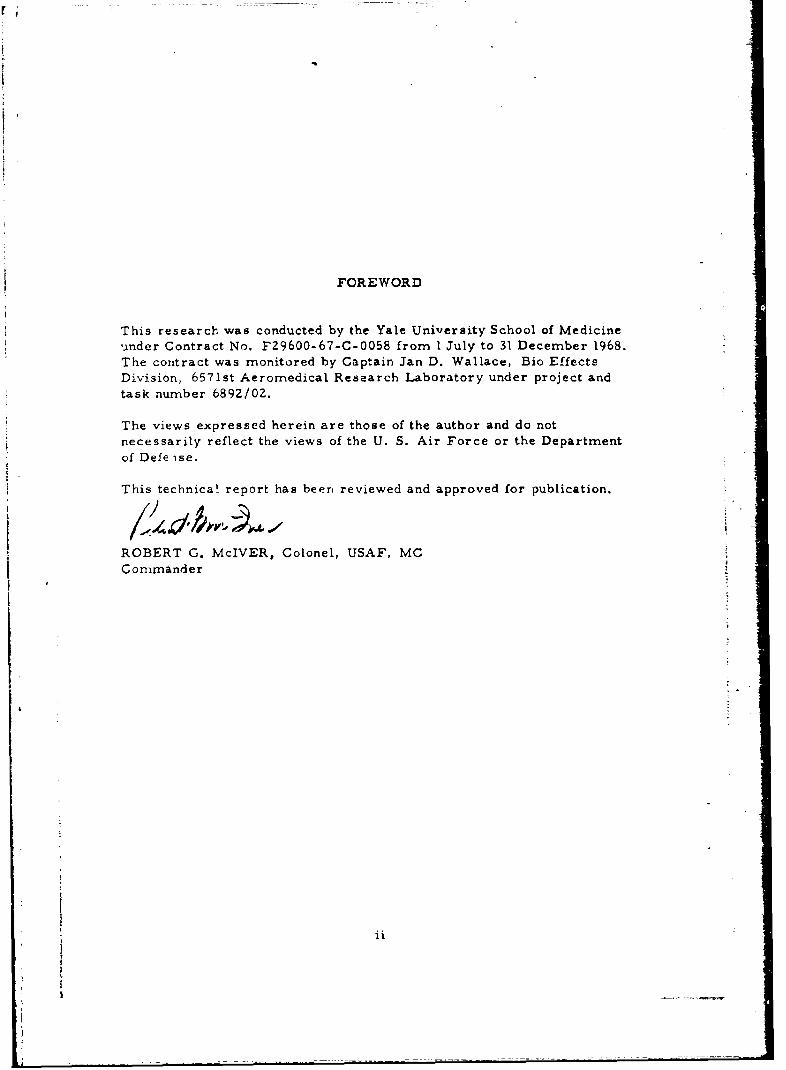
Figure 2 shows the control console and Figure 3 the block diagramof the control circuits. The circuit diagram is shown in Figure 4A and4B. With all three ON-OFF switches in the ON position the sequence ofsignals is as indicated in the timing diagram Figure 5. The letters inthe timing diagram refer to the parts of block diagram Figure 3 at whichthese signals occur. The repetition rate of the control sigrals is deter-mined by the astable multivibrator (b).
The frequency of this multivibrator can be varied by a frequencycontrol (a). This control varies the time constant of the frequency deter-mining RC network in conjunction with a voltage control which limits thecharge of the capacitor in the RC network and thus influence the frequency.
The monostable multivibrators (c) and (d) are triggered by alternatehalf cycles of multivibrator (b). Multivibrator (d) triggers a delaycircuit (e) which in turn triggers multivibrator (f). The outputs of thethree monostable multivibrators (c, d, and f) are connected each to oneinput of the three AND-gates (h, i, and k). Another input of each AND-gateis connected to an ON-OFF switch for each channel. The third input ofeach gate is connected to a subcarrier oscillator, one for each channel.With the switch for any one of the channels in the ON position and thecorresponding monostable multivibrator in the triggered (unstable) condi-tion the oscillator signal is allowed to pass through the gate to an OR(summing)-Gate which passes any of the three signals which arrives to thedriver circuit.
The duration of the ON-time of the monostable multivibrator deter-mines the duration of the actual current pulse from the stimulator. Asshown in the circuit diagram of the control circuit, Figure 4A, thetiming capacitor is charged by a constant current circuit which obtainsits reference voltage from the duration control (g). The duration controlis a step attenuator which determines the charging rate of the timingcapacitors in all three rnonostable multivibrators by varying the referencevoltage to the constant current circuit.
3

1-2
Figure 2. Control Console for the Three-Channel Transmitter
4

MUTVBCONTROL CONTROL
C tE
I m.1,0C.OC
CHANEL ICHANEL2CHANEL5

r I
20
o U)
- I _cc-J I 0 T
----- 0 -v0I-

15V
TV
2aic 22K ~ PZOUTPU
CM2~~~ ~ 'O 22 PWE UP
22KSA.S
50VV
2 ZKK
UK ~~ ~ ~ P 22 4p op0 UTUCH I 4.NK O GTE
ii igre B.Cirui Diga ofWE ConrolCPLY
I --
I I
I I
I I
I
I I
ICHI I CHZ CI43 CH I
Figure 5. Timing Diagram
8~1

The first two monostable circuits (c) and (d) are always triggeredone-half of a cycle of the astable multivibrator (b) apart while the thirdmonostable circuit (f) follows the second by a constant delay of approxi-mately I msec. This delay is provided by delay circuit (e), a singletransistor which is temporarily turned off by a negative potential at theinput capacitor. The duration of the off-time is determined by thecoupling capacitor and the bias resistor at the base.
There are three subcarrier oscillators (1, m, and n), one for eachstimulation channel. The oscillatc.'s employ a Golpitts circuit. Thebasic frequency determines the charinel and a variation of this frequencythe intensity of stimulation current. The intensity controls (o, p, and r)provided for each channel are variable capacitors in parallel to the tankcircuit inductor.
The gated subcarrier oscillator signals from the outputs of AND-gates(h, i, and k) are connected to the driver stage (t) vi- OR-gate (s).
B. ' ne Gated Power Supply
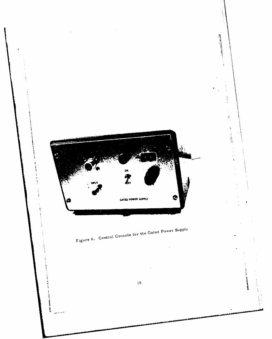
A photograph and a circuit diagram of this unit are shown inFigure 6 and Figure 7 respectively. The primary power is received fromthe A. C. supply line and stepped down in the power transformer. Thesecondary voltage is rectified, filtered and pre-regulated by transistorQl (2N3054) whose base is connected to D2, a 30 volt zener diode.
The input to the gating circuit is connected to the driver stage inthe control circuit section via transistor Q2 which is used as a fastdiode to decouple the base of the input transistor Q3 from the output ofthe driver. Transistor Q4 is switched by Q3. The collector of Q3 isconnected to zener diode D3 at 20V while its base is driven from 30V re-sulting in a forward operation of both transistor junctions. In this wayan accurate and low impedance reference voltage is supplied to the baseof output transistor Q5 when Q4 is turned on. In the off condition the baseof Q5 is clamped to ground potential by the collector of Q3 through thebase emitter junction of Q4. As a result, pulsed power is applied to thetransmitter at the rate of the frequency of the subcarrier oscillator whichis passed through at that time.
9
FigControl Console for the Oated power Supply
,ure 6
tt

C',
05.

t
C. The TrtnE aitttr
No schematic of h 'tta, 3mitter, 1l odel DG51I, is available. Itwas manufactured b'/ -ar.ders Associates and subsequently modified by
Systems Research Lab. , Inc. . The transmitter contains one transistor2N5108. The tuning and antenna coupling circuit is a cavity in the col-
lector of the transistor. A. tape in the cavity provides proper matchingto the : .nrtnni imredance.
Upo- al: li(-atior of power the transmitter begins to generate afrequency of 915 MHz and tcease. when the power is removed. A trainof ultra high frequency bur;ts is transmitted, therefore, at the rate ofthe subc-rrier t requercy, ., video output is provided to observe thedemodulated UMF -n an osc.,joscope. Figure 8 is a photograph of thetransmitter and th. ant erna.
D. The Anteanina
Connected to t'. tAi a rs i.er output is a cavity-backed spiral-intenna, AEL Model No, AkSN 115A, with circular polarization. Thistype of antenna was c',ose. to minimize directional effects at the rece;ver,
E. The 915 tc LCk; MHz -)own-Converter
To match the conventionally used stimulator which is operated at100 MHz a converter was acquired. This unit is self contained and was
designed and manufactured by Systems Research Lab. , Inc. 3. A photo-graph of the converter is shown in Figure 9 and the circuit diagram inFigure 10. The converter consists of a mixer, a lecal oscillator and anoutput stage. It is power,:d by t-wo 1. 4 volt mercury batteries of 500 rnAhwhich provide approximately 100 hours of continuous operation.
The RF signal is rcceivcd by a %emi-circular antenna with an inside
diameter of 0. 75 inch. A loose coupling into the stub-tuned oscillator
2Sandere Associates, 95 Canal Street, Nashua, New Hampshire3Systems Research Lab., Inc., 500 Woods Drive, Dayton, Ohio
kI
121
,a b ]I i n, a l |

ItI
Figure 8. Transmitter and A~ntenna Working at 915 MHz
13

-1 0
I 14

I uh
,S f -LI / 140 COAXPU
.5 AR UN 4ESSTO 710
ALL.9 R39SOR I/tOWAT
1.5

provides the mixing of the incoming signal with the oscillator frequencyto an intermediate frequency of 100 MHz which is amplifiei in the thirdtransistor and connected to the input of the stimulator.
F. The Stimulator
Manufactured by Neurotronics 4 , it is a self contained unitoperating from a 7 volt mercury battery. The stimulator receivesthe 100 MHz signal from the converter. It separates the subcarriersignals from the RF carrier and decodes the subcarrier signals intochannel and intensity information. The stimulator generates negativepulses from a current source, i. e. the current amplitude is determinedby the subcarrier signal, and is, within limits independent of the impe-dance of the load. Currents of up to 2. 5 ma into a load of up to 10 K ohmscan be generated. The unit is housed in an epoxy shell and potted in anepoxy compound. A circuit diagram is not available.
k
4 Neurotronics, 72 South Turnpike Road, Wallingford, Connecticut-
16

UnclassifiedSecunty Ciassifc ikn
DOCUMENT CONTROL DATA• R & Dt&*c~at~ty (Iass efl~ on o .it/.. holy of ab,rpr nd od--jii *nnoini'on .- ,,t he eteed .tn the o.s te -p-t l1 Cea.-1.d,
I ON5INTINQ ACI.-T, (C-p-at.g. uhor) 12.. R LrCRT SECL~RITY CLASSIFICA lION
Yale University School of Medicine U i. _o__U__
3 REPORT TITLE
UHF STIMULATION SYSTEM
4 DESC IP I vE NOTES (ryp. of ?opal( and InClan,, date@)
Interim 1 July 68 to 31 December 1968AIJ T700O41l1 r' tl. n~m.. middI.le Iul, l*.at fame)
Delgado, Jose M.R., and Weiss, Gerhard
6REPORT OATE 7s, TOTAL NO Or PAGES 7b. NO OF REFS
October 1969 16 1I&a CONTRACT OR GRANT NO 0., ORIGINATORS REPORT NuR EWSI
FZ9600-67-G-0058 ARL-TR-69-1Ib. PROjECT NO
6892C. 9h. Or ER REPORT NO(IS)(Any oth$. Ab@ra thotimny b*sainedrhia "Fport)
d.
1C- DISTRIPuTION STATEMENT
This document has been approved for public release and sale;its distribution is unlimited.
1 SUPPL EME. NTARy NOTES I S~P~ON50"INj 1JILITARY ACTIVITO
6571st Aeromedical Research Laboratory1N-clioman AFB, New Mexico 88330
A UHF remote stimulation system working in the 915 MHz band is de!cribed, which
generates current pulses in three stimulation channels. The amplitude, duration,
repetition rate and channel can be controlled from a remotely located control panel.
This system has been installed at Holloman Air Force Base, New Mexico, to stimulae
the brain of free ranging chimpanzees and study the induced modifications on individ-
ual and social behavior.
FORMDD NO *,1473 UnclassifiedSecur ,y ClasSL',Cat-On

Unclas sifiedSecurity Classification
4 LINK A LINK ft LINK CKEY *ORO S
ROLL: WT ROLE WT 4ROLE .1
UHF Stimulaticn SystemCurrent PulsesBrain StimulationFree- ranging ChimpanzeesIndividual BehaviorSocial Behavior
. - . -
£flCUOL DM*N*t*.*MIUnclassifiedj Scrt Classification


![UNIVERSITY OF CALCUTTA · Circuit, Frequency Response, Input and Output Impedance, Current and Voltage ... Astable and Monostable Multivibrator Circuits. [2 Lectures] Number System](https://static.fdocuments.in/doc/165x107/5e78cc61be82a533263558a8/university-of-calcutta-circuit-frequency-response-input-and-output-impedance.jpg)


![waveform generator multivibrator [Read-Only]ggn.dronacharya.info/.../Vsem/waveform_generator_multivibrator.pdf · •Three type of Multivibrator:- Astable (free running), monostable](https://static.fdocuments.in/doc/165x107/5fc8515215411b379f4f5bb9/waveform-generator-multivibrator-read-onlyggn-athree-type-of-multivibrator-.jpg)