ARISTEL NETWORKS MANUAL 3G VIDEO INTERCOM€¦ · has the option to see and speak with visitors at...
20
ARISTEL NETWORKS MANUAL 3G VIDEO INTERCOM AN1104 3G Video Intercom (ACCESS CONTROL SYSTEM) Please read these instructions before using. Keep for future reference. AN1104 3G Video Intercom 1 Revision E5 28 Jan 2013
Transcript of ARISTEL NETWORKS MANUAL 3G VIDEO INTERCOM€¦ · has the option to see and speak with visitors at...

ARISTEL NETWORKS
MANUAL
3G VIDEO INTERCOM
AN1104 3G Video Intercom
(ACCESS CONTROL SYSTEM)
Please read these instructions before using.
Keep for future reference.
AN1104 3G Video Intercom 1 Revision E5 28 Jan 2013

AN1104 3G Video Intercom 2 Revision E5 28 Jan 2013
TABLE OF CONTENTS
IMPORTANT SAFETY INSTRUCTIONS ................................................................... 3
AN1104 3G VIDEO INTERCOM INTRODUCTION .................................................. 4
AN1104 3G VIDEO INTERCOM WITH ACCESSORIES .......................................... 4
INSTALLATION .............................................................................................................. 5
AN1104 3G Video Intercom Unit .................................................................................. 6
Wiring Diagram ............................................................................................................... 6
LED Indicator ................................................................................................................. 7
AN1104 3G VIDEO INTERCOM OPERATION .......................................................... 8
Enter Listener Monitoring Mode ................................................................................... 10
Enter Access Control Mode........................................................................................... 10
Enter Programming Mode ............................................................................................. 10
Programming ................................................................................................................. 11
Door/ Gate Release ...................................................................................................... 13
Check GSM Signal Strength ........................................................................................ 15
Check Relay Status ....................................................................................................... 15
Door Opening Detection .............................................................................................. 15
Panel Opening Detection ............................................................................................... 15
Administrator Number .................................................................................................. 15
USER COMMANDS ............................................................................................................. 17
HOW TO RESET THE HARDWARE IF YOU FORGET YOUR PASSWORD ............... 18
SPECIFICATIONS .......................................................................................................... 18

AN1104 3G Video Intercom 3 Revision E5 28 Jan 2013
Thank you for purchasing the AN1104 3G Video Intercom. Please read this manual carefully
before using.
Be sure to keep this manual for future reference in case of any problem or question should arise.
IMPORTANT SAFTY INSTRUCTIONS
When using this AN1104 3G Video Intercom, basic safety precautions should always be followed
to reduce the risk of fire, electric shock and personal injury. Please read the following before using
your equipment.
1. Follow all warning and instructions on the product.
2. Unplug all the connections of product before cleaning. Do not use liquid cleaners or aerosol
cleaners. Use a damp cloth for cleaning.
3. Do not use this product near water.
4. Do not use this product near an area where there is a potential of gas leaks or near any fumes
that can be explosive.
5. Do not place this equipment near or over a radiator or any other heat source.
6. Do not overload the wall outlet or power cord where the power adapter is installed. This can
result in fire or electric shock
7. Avoid spilling liquids on this equipment and do not insert any objects through the ventilation
slots.
8. Avoid using the equipment during an electrical storm. There is a remote risk of electrical shock
from lighting.

AN1104 3G Video Intercom 4 Revision E5 28 Jan 2013
AN1104 3G VIDEO INTERCOM INTRODUCTION
The 3G Video Intercom AN1104 is an intercom system which can be installed at the entrance of a
building, factory, farm or car park. It is an ideal product to replace a traditional door phone. The user
has the option to see and speak with visitors at the door entrance via simple video call from a 3G/
UMTS mobile phone. The mobile doesn’t need operating system appliction, just 3G connection and the
ability to make video calls. The user, without this feature, will still be able to receive audio calls on their
mobile phone or land line.
Door or gate release is from the phone keypad by pressing * duration the conversation and can also be
activated by calling the SIM card in the unit from an authorized phone number, the unit will recognize
an authorized phone number calling it and will then reject the call without answering, free of charge.
Product main features:
1. Stainless-Steel faceplate, Weatherproof.
2. Standalone and Vandal resistant design.
3. Choose to use video or audio call feature
4. Rings up to 3 numbers in sequence.
5. Caller ID access by free call from an authorized phone number, up to 100 numbers.
6. Can be used for silent monitoring.
7. Ring time/ call time/ relay time is changeable.
8. Relay can control holding or releasing a gate or boom.
9. Simple programming via SMS
10. Works with power supplies in the range 12~24V AC/DC.
11. Check stored numbers via text message.
12. Works with mobile phones and land lines.
AN1104 3G VIDEO INTERCOM WITH ACCESSORIES
Item Description Q’ty Included Optional
1 AN1104 - 3G Video Intercom 1 佘
2 Power adapter 1 佘
3 Operational manual 1 佘

(Front View)
AN1104 3G Video Intercom 5 Revision E5 28 Jan 2013
INSTALLATION
This 3G Video Intercom is suitable for flush mounting.
(Side View) (Rear View)
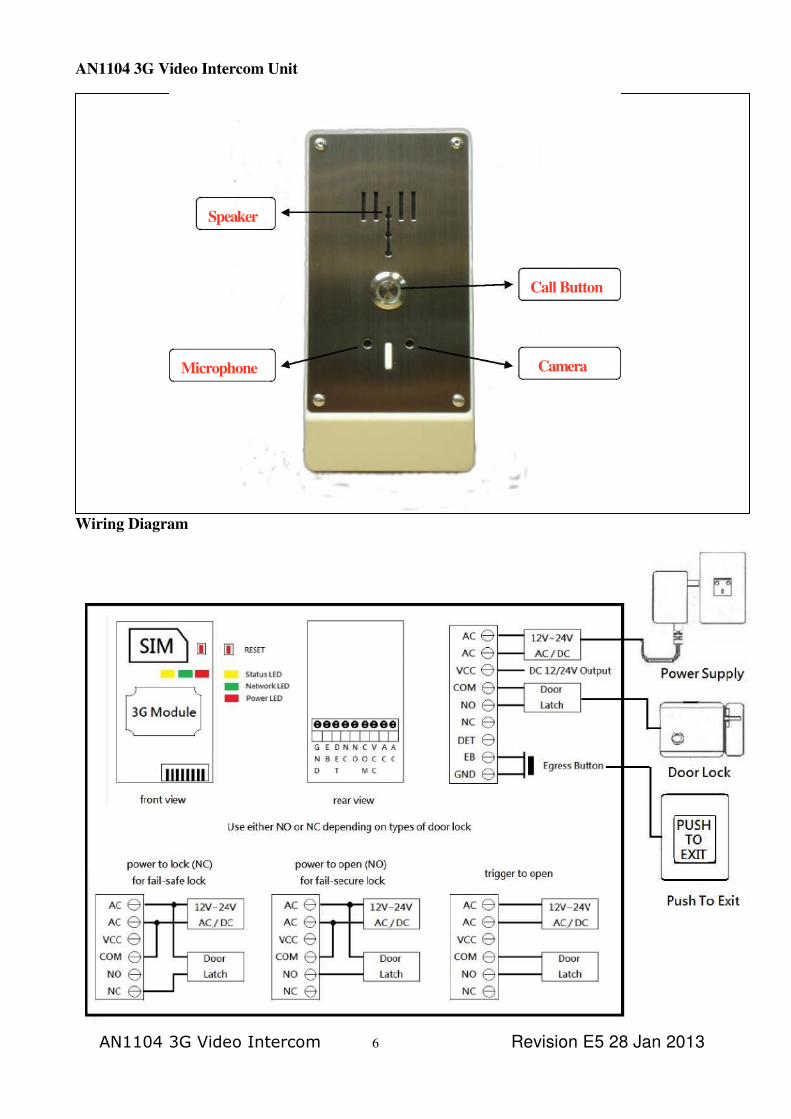
Microphone
Speaker
Call Button
Camera
AN1104 3G Video Intercom Unit
Wiring Diagram
AN1104 3G Video Intercom 6 Revision E5 28 Jan 2013

AN1104 3G Video Intercom 7 Revision E5 28 Jan 2013
LED INDICATORS
1. LED “Intercom Status “ Indicator
LED Status
Red (standby) 0.1sec ON / 2 sec OFF
Red (using) Solid
2. LED ‘Network “Indicator
LED Status
Red (ready) 1 sec ON/ 1 sec OFF
Red (searching) Solid
Red (busy) Solid
3. LED “ Power “ Indicator
LED Status
Red (power on) Solid
Red (power off) Off
1. SIM card
You MUST remove the PIN lock from the SIM before inserting it in the unit AN1104.
( use your mobile phone to remove the SIM PIN lock )
Insert the SIM card into the SIM card holder and close it carefully.
2. Power Supply
Connect a 12 volt DC power supply to terminals marked “AC” and “AC”
The AN1104 is designed to work with power supplies 12V~24V AC/DC.
The power supply should be capable of supplying a constant current of no less than 1amp,
3. Door Lock
Connect an electric door lock to terminals marked “door latch”.
AN1104 3G Video Intercom 8 Revision E5 28 Jan 2013
AN1104 3G VIDEO INTERCOM OPERATION
When the visitor pushes the call button to activate the AN1104 ring tone will be heard from the 3G Video
Intercom. At the same time connection is established with the phone number that is stored in the AN1104.
If the first number is busy or not answered the call can be diverted to another phone number, mobile or
landline. The remote phone answers the call from AN1104 and starts conversation or live video call with
the visitors. Open the gate or door by pressing * through your phone during the conversation. The relay
switches can also be temporarily or permanently switched on or off by press # and 1.
Enter system menu
There are three different modes under system menu.
1. Monitoring mode
2. Access control mode
3. Programming mode
To gain access to the system menu via dial in, follows these steps:
1. Call the telephone number of the 3G Video Intercom
2. Wait for the intercom to answer and signal by one beep to enter system menu
3. Press the password of the mode you would like to enter
4. Password correct one beep, password error 3 beeps.
5. 3 times failure attempt on password , hang up the call

No
Open the door without
answering the call
Programming mode
default [*12*1234#
_
System flow Chart
Dial in the 3G video
intercom
To search if the phone
number is stored in the list as
a door open ID.
(Nlax:100 numbers)
Y
e
s
Intercom would
answer the call
(signal by one beep)
Enter system menu
( enter the password for different modes)
incorrect 3 times failure
Hand up the call

AN1104 3G Video Intercom 9 Revision E5 28 Jan 2013
correct
monitoring mode
default *13*1212#
(audio only)
default *14*1212#
(audio & video)
correct
Access control mode
(password for door open )
default [*33*5678#

AN1104 3G Video Intercom 10 Revision E5 28 Jan 2013
Enter Monitoring Mode
1. Call the telephone number of the 3G Video Intercom
2. This device will then verify your phone number with your predefined numbers.
3. You will hear a “Do” tone to enter video monitoring mode by pressing[*14*1212$k]
where 1212 is the password.
4. The unit will then hang up the call and call you back with a video call and you will be able
to hear the live sound and see the video of the intercom’s surrounding environment.
5. If you only wish to hear the live sound of the intercom surrounding environment by
pressing[*13*1212$~]where 1212 is the password.
* Video monitoring may not work in some countries duo to restriction by the service
providers * Under the monitoring mode speaker is OFF.( press 35$~to turn on speaker )
* You can still press * to active relay under this mode but speaker must be ON status.
Enter Access Control Mode
1. Call the telephone number of the 3G Video Intercom.
2. This device will then verify your phone number with your predefined numbers.
3. You will hear a “Do” tone to enter access control mode by pressing[*33*5678$~]where
5678 is the password.
4. The door will be opened after enter the correct password
*(To open the door by password, if the number is not stored in the access control section)
Enter Programming Mode
1. Call the telephone number of the 3G Video Intercom
2. This device will then verify your phone number with your predefined numbers.
3. You will hear a “Do” tone to enter into programming mode by pressing[*12* 1234$~]where
1234 is the password.
4. You are now in the “programming mode”
Note: At the end of each command there can be one of the two indications:
Successful: a long “beep” tone, failed: three short “beep” tone.
5. To make changes on settings please refer to the user commands.(P16~ P18)
6. To end programming mode just hang up.
NOTE:
*To be successful in programming, originate a call from a land line and enter the digits slowly or using
programming by text message.

AN1104 3G Video Intercom 11 Revision E5 28 Jan 2013
Programming Programming can be carried out either by dial into the 3G Video Intercom or by text message
(Certain programming feature can only be set up by text message, please refer to user commands P.16)
Programming by text message
Programming by text message is the simplest way to customize the settings of the 3G Video
Intercom and add or delete telephone numbers. Simply send texts in the format to the telephone
number of the SIM within the 3G Video Intercom.
Note:
1. A SMS text messages is limited to 140 characters.
2. You can program many different user command codes in one text message with SMS command
format. *12*1234 # [command Code1] # [command Code 2] # [command Code3] # ......
3. Refer to user command table on P.16~18
Program a call button phone number and choose to use audio or video call via SMS
The users have the options either to use video or audio calls by pre-programming the 3G video intercom
For video calls it can only work with mobile phone has ability to make video calls; currently most
of Nokia and Samsung mobiles can support this feature. iPhone does not support video calls but
audio only due to restrictions by Apple Inc.
Check if your mobile phone has ability to make video calls

AN1104 3G Video Intercom 12 Revision E5 28 Jan 2013
Example:
Program a call button phone number and choose to use audio or video call via SMS
058 57235 (landline number 1)
086 5682554 (mobile number 2) mobile has ability to make video call.
086 2235644 (mobile number 3) mobile has no ability to make video
call.
SMS format:
*12*1234#11105857235#1220865682554#1310862235644#
Other examples:
Delete 2&3 phone numbers from a call
button SMS format:
*12*1234#12*#13*#
User command code CORRECT
SMS format:
*12*1234#11105857235#1220865682554#1310862235644#
SMS reply:
11105857235#1220865682554#1310862235644# OK
User command code ERROR (user command 129
error) SMS format:
*12*1234#11105857235#1290865682554#1310862235644#
SMS reply:
1110587235#1290865682554# Error

AN1104 3G Video Intercom 13 Revision E5 28 Jan 2013
Programming by dial in
Note: programming dial in can’t be used from telephones which are already programmed to
open the door when they dial the 3G Video Intercom but you can disable Caller ID display
(withhold the number) on the mobile before using.
To gain access to the programming mode via dial in, follows these steps:
Example:
Storing a telephone number for dial in door release
Enter Programming Mode by Pressing .....
*12*1234# (1234 is default password)
A successful pass code will produce a single long beep. A failed attempt will produce 3
short bleeps.
You may now program up to 100 telephone numbers into memory.
Use the following commands to program the unit
* Insert international country code (1~3 digits): 71 [country code] #
* Add a number (up to 100 numbers): 72 [ telephone number] # *
Delete a number: 73 [ telephone number] #
* Delete all numbers: 73*#
Door /Gate Release (ring in to open)
This 3G Video Intercom also has an extra feature to allow user to gain access from their phone
by two methods.
1. by Caller ID recognition
2. by access control password mode
1. Caller ID recognition to open
Ring in to open the door for authorized telephone number. It can support for up to 100 users.
When 3G Video Intercom receives a call from user, it will check the calling number and if the
number is in the list, the 3G Video Intercom will drop the call and then open the gate / door. The 3G
Video Intercom doesn’t answer the call, it simply checks the caller ID, and so it won’t cost you anything to open the gate / door.
AN1104 3G Video Intercom 14 Revision E5 28 Jan 2013
For Caller ID recognition to open the door or gate you need to program the mobile
numbers and country code into the memory before using.
*To be successful we strongly suggest programming via text message.
Example:
Ireland Country code: 353 (UK: 44 / USA: 1)
086 5683624 (mobile number 1)
086 5682554 (mobile number 2)
086 2235644 (mobile number 3)
SMS format:
*12*1234#71353#720865683624#720865682554#720862235644#
To delete phone numbers of dialing in to open
SMS format: (to delete phone number 1 and 2)
*12*1234#730865683624#730865682554#
SMS format: (to delete all numbers)
*12*1234#73*#
After the numbers are programmed you can also send the text message to check the stored
numbers by sending SMS format *21# , then the 3G Video Intercom will reply the phone
number list text message.
2. Access control password to open
Dial the SIM card telephone number. The unit will answer the call and you will hear a bleep
tone.
To activate relay by pressing *33*5678# (5678 is default password), the door can be
opened after enter correct command code.
*This is for door open option for telephone numbers not stored.

AN1104 3G Video Intercom 15 Revision E5 28 Jan 2013
Check signal strength (0~31 levels)
When a request for signal strength SMS is sent to the 3G Video Intercom it will reply with a
signal strength code, service provider name and current network (GSM or WCDMA).The signal
strength code will be between 0~31 means the signal level is from poor to best. When the unit
detects the WCDMA network signal is poor will automatically switch to GSM to get better signal.
Example
SMS format: *20#
SMS reply: Vodafone , WCDMA, Signal Level = 31 [Signal is very strong]
Check Relay & Detect (input) Status
You can send SMS command code to check relay status and Detect status.( checking door is opened
or closed)
SMS format: *22#
SMS reply: Relay=ON Detect = ON[Relay=Hold , Detect=GND]
Door opening detection
Terminal mark” DET” input” (see wiring diagram P6) is for you to connect a door sensor. The gate would have a door sensor wired through ”DET” input to ground. When the door sensor is triggered, a SMS message” door open alarm” is sent to the predefined call button phone numbers.
Panel opening detection
A panel opening sensor is built inside the electronic board, once the panel of 3G video intercom has
been removed, the alarm will go off from the speaker and a SMS message” panel open alarm” is
sent to the predefined call button phone numbers.
Administrator Number
Once the administrator number is stored in the unit whether programming via dialing in or text
messages, can only be carried out by this number.
Example:
Program a mobile number as an administrator number via SMS
Mobile number: 0865682554
SMS format *12*1234#740865682554#
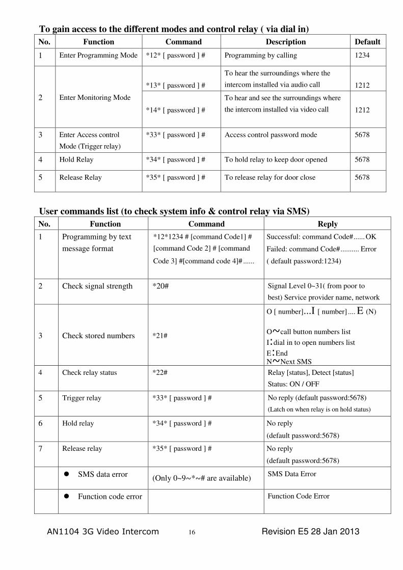
To gain access to the different modes and control relay ( via dial in)
No. Function Command Description Default
1 Enter Programming Mode *12* [ password ] # Programming by calling 1234
2 Enter Monitoring Mode
*13* [ password ] #
To hear the surroundings where the
intercom installed via audio call 1212
*14* [ password ] #
To hear and see the surroundings where
the intercom installed via video call 1212
3 Enter Access control
Mode (Trigger relay)
*33* [ password ] # Access control password mode 5678
4 Hold Relay *34* [ password ] # To hold relay to keep door opened 5678
5 Release Relay *35* [ password ] # To release relay for door close 5678
User commands list (to check system info & control relay via SMS)
No. Function Command Reply
1 Programming by text
message format
*12*1234 # [command Code1] #
[command Code 2] # [command
Code 3] #[command code 4]# ......
Successful: command Code# ...... OK
Failed: command Code# .......... Error
( default password:1234)
2 Check signal strength *20# Signal Level 0~31( from poor to
best) Service provider name, network
3 Check stored numbers *21#
O [ number]...I [ number] .... E (N)
O~call button numbers list
I:dial in to open numbers list
E:End N~Next SMS
4 Check relay status *22# Relay [status], Detect [status]
Status: ON / OFF
5 Trigger relay *33* [ password ] # No reply (default password:5678)
(Latch on when relay is on hold status)
6 Hold relay *34* [ password ] # No reply
(default password:5678)
7 Release relay *35* [ password ] # No reply
(default password:5678)
SMS data error (Only 0~9~*~# are available)
SMS Data Error
Function code error Function Code Error
AN1104 3G Video Intercom 16 Revision E5 28 Jan 2013

AN1104 3G Video Intercom 17 Revision E5 28 Jan 2013
User commands table
No. Feature Command Description Default
1 Change password of
Programming Mode
01 [new password ] # password:4 digit codes 1234
2 Change password of Access
control Mode
02 [new password] # password:4 digit codes 5678
3 Change password of
Monitoring Mode
03 [new password ] # password:4 digit codes 1212
4
Store a call button phone
number
1 [ Y][X][ phone number] # Y:1~3 (sequence of phone number)
X:1 (audio call) X:2 (video call)
Phone No. : 3~15 digit codes
None
5 Delete a call button
Phone number
1 [Y] *# Y:1~3 (sequence of phone number) None
6 Speaker Volume 3 [ speaker volume] # volume: 0~4 levels 3
7 Microphone Volume 4 [ microphone volume] # volume: 0~4 levels 3
8 Relay Time 51 [ relay time] # relay time: 1~9999 sec 1
9 Divert to second no. time 52 [ divert time] # divert time :10~99 sec
(2 digit codes)
20 sec
10 Call Time 53 [call time] # call time:005~999 sec
(3 digit codes)
060 sec
11 Monitoring duration time 55 [time] # time:00~60 minutes
00 ( no restriction)
10 mins
12 Change trigger relay code 61 [ X ] # X: 0~9 / * /#
*
13 Change hold relay code 63 [ X ] # X: 0~9 / * /#
#
14 Change release relay code 64 [ X] # X: 0~9 / * /#
1
15 Ring in to open the door
(Max: 100 numbers)
71 [ country code ] #
72 [ Add a phone number] #
73 [ Del a phone number ] #
73*#
Country code:1~3 digit codes
Add a number: 3~15 digit
codes Del a number: 3~15 digit
codes Del all phone numbers
886
16
Add administrator phone
number
74 [ admin number] # admin number: 3~15 digit codes
( no number no restriction) None
17 Delete administrator
phone number
74*# delete administrator phone
number
None
18 Door opening detection 81 [ X ] #
X: 0, 1 ,2
0 = OFF / 1=GND
2= EOL (10Kohm)
Off

19 Panel opening alarm 82 [ X ] # X: 1 , 2
1= alarm / 2= SMS & alarm
alarm
20 Reset 999# reset default None
How To Reset The Hardware When You Forget your Password
AN1104 3G Video Intercom Specification
Operating Voltage 12 ~ 24 Volt AC/DC
Operating Current Maximum 250mA, Typically 55mA
UMTS Frequency 850/1900 MHz for Telstra & Vodafone or 900/2100 MHz for Optus.
Camera CMOS camera module / 2 megapixel / lens angle 65.5侻
Physical material Stainless Steel and ABS
Physical size 164 x 81 x 20 mm
Weight 265g
Humidity Less than 80% RH
Operating Temperature -20°C to +50°C
Protection Index IP 65
AN1104 3G Video Intercom 18 Revision E5 28 Jan 2013
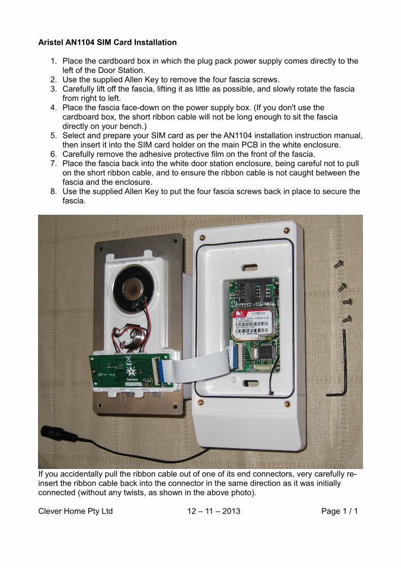
Aristel AN1104 SIM Card Installation
1. Place the cardboard box in which the plug pack power supply comes directly to the left of the Door Station.
2. Use the supplied Allen Key to remove the four fascia screws.3. Carefully lift off the fascia, lifting it as little as possible, and slowly rotate the fascia
from right to left.4. Place the fascia face-down on the power supply box. (If you don't use the
cardboard box, the short ribbon cable will not be long enough to sit the fascia directly on your bench.)
5. Select and prepare your SIM card as per the AN1104 installation instruction manual,then insert it into the SIM card holder on the main PCB in the white enclosure.
6. Carefully remove the adhesive protective film on the front of the fascia.7. Place the fascia back into the white door station enclosure, being careful not to pull
on the short ribbon cable, and to ensure the ribbon cable is not caught between the fascia and the enclosure.
8. Use the supplied Allen Key to put the four fascia screws back in place to secure the fascia.
If you accidentally pull the ribbon cable out of one of its end connectors, very carefully re-insert the ribbon cable back into the connector in the same direction as it was initially connected (without any twists, as shown in the above photo).
Clever Home Pty Ltd 12 – 11 – 2013 Page 1 / 1