ARINC 429 Decoder, Users Manual - LAHNISS 429 Decoder, Users Manual 5 | P a g e Once the Bitrate is...
25
ARINC 429 Decoder, Users Manual 1 | Page ARINC 429 Decoder, Users Manual January 2013 Contents 1 Introduction ........................................................................................................................................................................................................................................ 2 2 The User Interface............................................................................................................................................................................................................................... 3 2.1 Overview of the tabs offered by the ARINC Decoder .......................................................................................................................................................................................... 3 2.2 The Basic Tab ....................................................................................................................................................................................................................................................... 4 2.3 The User Defined Tab .......................................................................................................................................................................................................................................... 6 2.4 The Filter Tab ....................................................................................................................................................................................................................................................... 7 2.5 The Level Tab ....................................................................................................................................................................................................................................................... 8 2.6 The Search Tab .................................................................................................................................................................................................................................................. 10 3 The Decode Modes ........................................................................................................................................................................................................................... 12 3.1 The 8+24 bit Decode Mode ............................................................................................................................................................................................................................... 12 3.2 The 8+2+19+2+1 bit Decode mode ................................................................................................................................................................................................................... 13 3.3 The Symbolic Decode Mode .............................................................................................................................................................................................................................. 14 4 Appendix A: Symbolic Decoding in More Details.............................................................................................................................................................................. 15 4.1 Explanation of the User Label Definition File .................................................................................................................................................................................................... 15 4.1.1 Terminology, Conventions ........................................................................................................................................................................................................................................................ 15 4.1.2 Terminology .............................................................................................................................................................................................................................................................................. 15 4.1.3 Line Syntax ................................................................................................................................................................................................................................................................................ 16 4.1.4 Line Contents following ARINC 429 ........................................................................................................................................................................................................................................... 17 4.1.5 Deviations from ARINC 429 ....................................................................................................................................................................................................................................................... 17 4.1.6 Extensions to ARINC 429 ........................................................................................................................................................................................................................................................... 17 4.1.7 Unused Tokens .......................................................................................................................................................................................................................................................................... 17 4.2 Examples used in this document ....................................................................................................................................................................................................................... 17 4.3 Discrete Labels .................................................................................................................................................................................................................................................. 18 4.3.1 Enumerated type for Discrete Labels ........................................................................................................................................................................................................................................ 19 4.3.2 BCD Signal for Discrete Labels ................................................................................................................................................................................................................................................... 20 4.3.3 Binary Signal for Discrete Labels ............................................................................................................................................................................................................................................... 21 4.3.4 Combining Signals into Discrete Labels ..................................................................................................................................................................................................................................... 22 4.3.5 Common Signals found in many Labels ..................................................................................................................................................................................................................................... 24
Transcript of ARINC 429 Decoder, Users Manual - LAHNISS 429 Decoder, Users Manual 5 | P a g e Once the Bitrate is...

ARINC 429 Decoder, Users Manual 1 | P a g e
ARINC 429 Decoder, Users Manual
January 2013
Contents 1 Introduction ........................................................................................................................................................................................................................................ 2
2 The User Interface............................................................................................................................................................................................................................... 3
2.1 Overview of the tabs offered by the ARINC Decoder .......................................................................................................................................................................................... 3
2.2 The Basic Tab ....................................................................................................................................................................................................................................................... 4
2.3 The User Defined Tab .......................................................................................................................................................................................................................................... 6
2.4 The Filter Tab ....................................................................................................................................................................................................................................................... 7
2.5 The Level Tab ....................................................................................................................................................................................................................................................... 8
2.6 The Search Tab .................................................................................................................................................................................................................................................. 10
3 The Decode Modes ........................................................................................................................................................................................................................... 12
3.1 The 8+24 bit Decode Mode ............................................................................................................................................................................................................................... 12
3.2 The 8+2+19+2+1 bit Decode mode ................................................................................................................................................................................................................... 13
3.3 The Symbolic Decode Mode .............................................................................................................................................................................................................................. 14
4 Appendix A: Symbolic Decoding in More Details .............................................................................................................................................................................. 15
4.1 Explanation of the User Label Definition File .................................................................................................................................................................................................... 15
4.1.1 Terminology, Conventions ........................................................................................................................................................................................................................................................ 15 4.1.2 Terminology .............................................................................................................................................................................................................................................................................. 15 4.1.3 Line Syntax ................................................................................................................................................................................................................................................................................ 16 4.1.4 Line Contents following ARINC 429 ........................................................................................................................................................................................................................................... 17 4.1.5 Deviations from ARINC 429 ....................................................................................................................................................................................................................................................... 17 4.1.6 Extensions to ARINC 429 ........................................................................................................................................................................................................................................................... 17 4.1.7 Unused Tokens .......................................................................................................................................................................................................................................................................... 17
4.2 Examples used in this document ....................................................................................................................................................................................................................... 17
4.3 Discrete Labels .................................................................................................................................................................................................................................................. 18
4.3.1 Enumerated type for Discrete Labels ........................................................................................................................................................................................................................................ 19 4.3.2 BCD Signal for Discrete Labels ................................................................................................................................................................................................................................................... 20 4.3.3 Binary Signal for Discrete Labels ............................................................................................................................................................................................................................................... 21 4.3.4 Combining Signals into Discrete Labels ..................................................................................................................................................................................................................................... 22 4.3.5 Common Signals found in many Labels ..................................................................................................................................................................................................................................... 24

ARINC 429 Decoder, Users Manual 2 | P a g e
List of Figures Figure 1 Tabs overview for ARINC 429 ........................................................................................................................................................................................................ 3 Figure 2 ARINC 429 Search tab, when Zoom is sourced on Decoded Trace ............................................................................................................................................... 3 Figure 3 The Basic Tab ................................................................................................................................................................................................................................ 4 Figure 4 Measuring the Signal bitrate using the Time cursors ................................................................................................................................................................... 4 Figure 5 he User Defined Tab and its controls ............................................................................................................................................................................................ 6 Figure 6 The Filter Tab and its actions when using “Only Show Listed Labels” .......................................................................................................................................... 7 Figure 7 Level Tab Controls ......................................................................................................................................................................................................................... 8 Figure 8 Looking at the levels in detail. ...................................................................................................................................................................................................... 8 Figure 9 Rescuing a troubled Signal with manually tuned Levels ............................................................................................................................................................... 9 Figure 10 The Column to Search Selection ............................................................................................................................................................................................... 10 Figure 11: Signal decoded in the 8+24 bits mode ..................................................................................................................................................................................... 12 Figure 12: Signal decoded in the 8+2+19+2+1 bit mode .......................................................................................................................................................................... 13 Figure 13: Example of ULDF file, with several USigD for Label 273 of a civilian GPS ................................................................................................................................ 14 Figure 14:Listing of all Fields of the USigD line, with comments .............................................................................................................................................................. 16 Figure 15: Visual explanation of each relevant token of an enumerated type ........................................................................................................................................ 19 Figure 16: Visual explanation of each relevant token of a BCD type ........................................................................................................................................................ 20 Figure 17: Visual explanation of each relevant token of an binary type .................................................................................................................................................. 21 Figure 18: Combining 3 User Signals into single Label 212 ....................................................................................................................................................................... 22 Figure 19: User defined interpretation of the Date Label 260 ................................................................................................................................................................. 23 Figure 20: Table showing commonly found signals ................................................................................................................................................................................. 25
1 Introduction Beginning with Release 7.1 of the firmware, several improvements have been made to the ARINC 429 Decoder. The vast majority of those pertain to the Symbolic
Decoding, driven by the User Label Definition files. The system has become clearer, and easier to use for those wishing to harness the power of symbolic decode.
We gladly thank E. Schütz formerly at SRTechnics, A. Netz and P. Lemberger at Avionik Straubing, D. Michaux at the University of Bordeaux, B. Morel and C.
Wittwer at Ruag, A. Therry at Zodiac, F. Raimondi at Teledyne LeCroy. All of them have contributed through their help and comments to the improvements of this
release.

ARINC 429 Decoder, Users Manual 3 | P a g e
2 The User Interface
2.1 Overview of the tabs offered by the ARINC Decoder
The User Interface of the ARINC 429 Decoder consists of 4 Tabs under the Decoder. Each one of the Tabs will be described in details in the following pages. An
additional Tab is located under the Zoom controls whenever a decoded Zoom is in use.
Figure 1 Tabs overview for ARINC 429
Figure 2 ARINC 429 Search tab, when Zoom is sourced on Decoded Trace
As in all most other decoders, there is no strict order in which to visit the tabs, except for setting the bitrate in the Basic tab. Once the decoding is correct, all the
controls might be used in any order. Experience shows that the usage modes are as diverse as the users. The problem at hand usually dictates the usage, and the
course of action. This document will attempt to convey usage hints in connection with the features described.
Also note that the common decode infrastructure such as the “Configure Table” and the “Export Table” buttons at the bottom of the Decode Setup Tab are
documented in the Teledyne LeCroy Serial Data Manual.

ARINC 429 Decoder, Users Manual 4 | P a g e
2.2 The Basic Tab
Figure 3 The Basic Tab
The Basic Tab offers the fundamental controls driving the decoding algorithm. Before looking at any other functionality, the Bitrate needs to be set correctly. In
Many cases the system user will know the bitrate and introduce it in the corresponding field. As ARINC predominantly uses 12.5 kbits/s or 100 kbit/s it is usually a
simple choice. If there are any doubts on the bitrate of the ARINC stream take a moment to measure it, with the following simple method.
Figure 4 Measuring the Signal bitrate using the Time cursors
As the Bitrate governs the decoding, it is important to have it right from the onset. The simplest method is to use the Horizontal Relative Cursors. By positioning
each cursor on equivalent positions of 2 consecutive bits, the 1/delta X read out will yield the Bitrate. Here we chose to measure on the beginning of each bit
plateau. The readout of 102.9 Khz can be rounded to 100 KHz and is good enough for the decoding algorithm.

ARINC 429 Decoder, Users Manual 5 | P a g e
Once the Bitrate is selected, we will usually start with the 8+24 bit Decoding, until we have reached the conviction that our stream is decoded correctly.
The Viewing Mode is Binary, Hexadecimal, or Decimal. It governs some of the rendering both in the table and the annotation. Usually the task at hand will dictate
the Viewing Mode. Note that it can be switched at any time during the course of a session.
The Details check box allows the rendering of low level details such as hexadecimal of BCD digits. Its importance also depends on the intent of the work. In some
cases it is necessary to track down the origin of a value to the individual BPRZ bits of the signal.
At this stage a word of caution on the signal polarity. ARINC 429 is usually transmitted over a twisted pair. When probing single ended at the individual lines of
the pair, the signal appears either normal or inverted. If, by accident the decoder input is using the inverted signal, all Label value will appear complemented to
377. In fact everything will look right, even the Parity bit, but none of the Labels expected for the Equipment will appear! It is enough to switch the probe to the
other wire to get the right information contents. If for any reason the positive signal cannot be probed, it is also easy to check the “Invert” control in the channel
dialog. The “Invert” control numerically flips the signal in the channel, and avoids having to electrically invert it.
Note that the inversion of polarity can also occur when using a differential probe whose inputs leads have been inadvertently swapped. In this case it is
recommended to swap the leads and verify that the pair polarity is correct. It goes without saying that the polarity of the line on the aircraft is essential.

ARINC 429 Decoder, Users Manual 6 | P a g e
2.3 The User Defined Tab
The User Defined Tab contains all of the necessary controls when working in User Defined Mode. The contents are explained here, but refer to Appendix A for all
of the detailed explanation on Terminology, concepts and Syntax of the ULDF files.
Figure 5 he User Defined Tab and its controls
The "User Defined" tab contains the File Selection Widget necessary to pick a ULDF. The primary modus operandi is to have a Dedicated File for each ARINC 429
Equipment. When a given channel is connected to the Equipment and Decoded, this File can be selected here and loaded. When the “User Defined” mode is
selected in the Basic tab, all of the messages will be interpreted based on the ULDF.
The Browse button leads to the File Picker. The Load button reloads the file when it has been edited in parallel. When creating the ULDF files, it is convenient to
proceed step by step to verify the correct decoding while adding Signal to the ULDF.
The Clear button Clears the internal Database of USigD. When the Database is cleared, all of the Labels will appear with only Label and Parity bit decoded.
The ULDF Contents box reflects the currently loaded database. It shows the total number of Labels in the Database, as well as the total number of Signals. It also
shows the number of Signals of each type, E stands for Enumerated, BCD and Binaries. This control is grayed out because its values are not user selectable, but
rather computed by the parsing algorithm of the ULDF file.
ARINC 429 Decoder, Users Manual 7 | P a g e
2.4 The Filter Tab
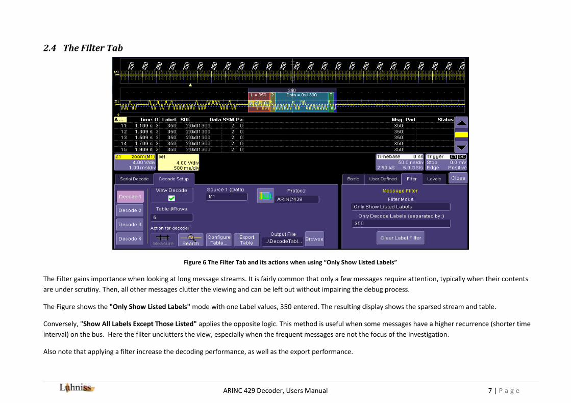
Figure 6 The Filter Tab and its actions when using “Only Show Listed Labels”
The Filter gains importance when looking at long message streams. It is fairly common that only a few messages require attention, typically when their contents
are under scrutiny. Then, all other messages clutter the viewing and can be left out without impairing the debug process.
The Figure shows the "Only Show Listed Labels" mode with one Label values, 350 entered. The resulting display shows the sparsed stream and table.
Conversely, "Show All Labels Except Those Listed" applies the opposite logic. This method is useful when some messages have a higher recurrence (shorter time
interval) on the bus. Here the filter unclutters the view, especially when the frequent messages are not the focus of the investigation.
Also note that applying a filter increase the decoding performance, as well as the export performance.

ARINC 429 Decoder, Users Manual 8 | P a g e
2.5 The Level Tab
Figure 7 Level Tab Controls
The Level Tab contains 6 controls out of which only 4 are visible at any point in time. This is due to the fact that the Levels can be specified either in Percent or in
Volts, with the corresponding values being shown.
The Level selection is largely automated since by default both levels are set to be in percent of the amplitude. This simplifies the initial learning, but it is important
to make sure the levels are set correctly to get a correct decoding. The level become very important when dealing with pathological signals.
Figure 8 Looking at the levels in detail.
By default the levels are set to be at 35% and 65 % of full amplitude on the BPRZ signal. In most cases, this is a perfect choice for ARINC 429 and immediately leads
to correct decode. However this only works if the signal is clean, as in the Figure, and the levels do not cross the Baseline noise or the Plateau noise. The following
image will look at an example where the levels have to be tuned manually.

ARINC 429 Decoder, Users Manual 9 | P a g e
Figure 9 Rescuing a troubled Signal with manually tuned Levels
This is a real world trace. Signals can be noisy, unbalanced, or corrupted in many other ways. In this case we would have to manually tune the levels to decode. In
some cases it is easier to use the Absolute level setting, in Volts. It is also possible to have one level in % and the other one Absolute.
Click on the image. This example shows 3 signals: M2 ,F1 and F2. F1 and F2 are identical traces. Both of them are based on M2, with the same Gaussian noise
added. If you look closely at the images you will see that F2 decodes correctly thanks to the manually tuned levels. F1 is incorrect because the levels cross into the
noise, where indicated by the red violation circles.

ARINC 429 Decoder, Users Manual 10 | P a g e
2.6 The Search Tab
Figure 10 The Search Tab when used on a Decoder
The search tab is available when a Zoom is connected to a decoded Trace. In this situation the normal Zoom controls are augmented by the Search Controls, as
show in the Figure above.
Figure 10 The Column to Search Selection
The “Column to Search” selection shows all of the columns generated by the ARINC 429 decoder.

ARINC 429 Decoder, Users Manual 11 | P a g e
The set of single arrow buttons allow moving from field to field, with or without added condition.
The set of double arrow buttons jump to the beginning and end of the record.
The set of play/stop buttons start/stop scrolling from the current position.
The “Use Value” box allows a search by value on the selected columns. The search criterion is context sensitive, which is reflected by the type of value (decimal,
hexadecimal, text and float)
A separate document contains more details on the search and its behavior.

ARINC 429 Decoder, Users Manual 12 | P a g e
3 The Decode Modes
3.1 The 8+24 bit Decode Mode
The simplest of all modes (8bits +24bits) displays the Label and the data field in hexadecimal. Notes that nibbles are swapped since they are encoded LSN first
Figure 11: Signal decoded in the 8+24 bits mode
This mode is very useful when starting the work, to quickly verify that each Label indeed contains 32 bits. For example in the image above it is immediately clear
that the Label contains 8 bits, and the Data 24 bits grouped in 6 BCD digits of 4 bits.

ARINC 429 Decoder, Users Manual 13 | P a g e
3.2 The 8+2+19+2+1 bit Decode mode
The second hexadecimal mode (8+2+19+2+1) also decodes in hexadecimal, but separates the SDI and SSM from the data bits. The SDI and SSM fields can also be
represented in the Symbolic Decode Mode with more flexibility.
Figure 12: Signal decoded in the 8+2+19+2+1 bit mode

ARINC 429 Decoder, Users Manual 14 | P a g e
3.3 The Symbolic Decode Mode
This mode is the richest of all the 3 modes and it is described in the following sections. Unlike the simple modes, it requires the user to provide a definition file,
containing the description of the signals emitted by the equipment.
When using the Symbolic mode (also known as User Defined or User Interpreted) the data field of each Label is decoded according to a file supplied by the user,
for its own system and equipment. Each Label value is decoded independently. The syntax of this file is described in detail in Appendix A. Examples are also
provided.
A text file drives the interpretation algorithm. The following image gives a feeling for these files, under a simple editor such as Notepad for MS Windows.
Figure 13: Example of ULDF file, with several USigD for Label 273 of a civilian GPS

ARINC 429 Decoder, Users Manual 15 | P a g e
4 Appendix A: Symbolic Decoding in More Details
4.1 Explanation of the User Label Definition File
4.1.1 Terminology, Conventions
4.1.2 Terminology
The file is called ULDF (User Label Definition File)
It is expected that each Equipment (for example a radio Altimeter, or a GPS) requires one ULDF.
Variations of the same Equipment manufactured over decades could also require different ULDF files to accommodate differences of precision (Altitude precision
to the meter or decimeter) or additional Labels (Support for GPS auxiliary results). However there can be unused information in a ULDF file. If a piece of Equipment
was emitting Labels 102,103,104,105 in its 1978 version and additionally Label 203,204,204 in its 1995 version, the same ULDF file could be used.
A line in the ULDF file is called a USigD (User Signal Definition). A USigD contains rules to interpret bits in an ARINC message. The Altitude, or the Distance To go,
or the fuel Level in Tank 4 each require a USigD. Some parameters require more than a single USigD, for example the Date requires several BCD USigDs.
A ULDF is therefore made up of one or more USigD There is no limit for the number of USigDs in a Label.
USigDs beginning with the same Label will appear with all Labels of that value in the annotation and the table.
All Labels of the same value are decoded according to that same rule, as per ULDF
When the frequent (but not always used) fields SDI and SSM are desired, they will need a one line USigD per Label in which they are desired. Examples are given
further in this document.
When the frequent (but not always used) sign field of a binary signal is desired, it will require a one line USigD.
Several fields (also called tokens) of the USigD are not used at present time, but retained for compatibility with the Standard. They might become useful in the
future.

ARINC 429 Decoder, Users Manual 16 | P a g e
4.1.3 Line Syntax
The text elements explain the syntax of the ULDF files are always shown in Helvetica.
The line structure one a single USigD in the Comma Separated File (CSV) contains 12 to 14 tokens, separated by commas as follows:
Label1,EquipementID
2,Name
3,Units
4,Min
5,Max
6,SigBits
7,PosSense
8,Resolution
9,MinTransit
10,MaxTransit
11,LabelType1
12,Offset
13,Detai
lsList14
Each USigD’s element has the following syntactic rules:
Name of the field Type of contents Range Used by algorithm 1 Label
1 Decimal 0 to 377 Yes
2 EquipementID2 Text Free text No
3 Name3 Text Free text Yes
4 Units4 Text Free text Yes, for Binary and BCD USigD only
5 Min5 Text Free text No
6 Max6 Text Free text No
7 SigBits7 Decimal 1-32 Yes, by all subtypes
8 PosSense8 Text Free text No
9 Resolution9 Decimal -max double to + max double Yes, for Binary and BCD USigD only
10 MinTransit10
Text Free text No
11 MaxTransit11
Text Free text No
12 LabelType112
Keyword Label_Discrete Yes
13 Offset13
Decimal 0-31 Yes
14 DetailsList14
Special format, see below Yes
Figure 14:Listing of all Fields of the USigD line, with comments
ULDF files support commented lines starting with // as the normal C++ convention. Comment can also be added at the end of the line, but not in the middle of the
token list.

ARINC 429 Decoder, Users Manual 17 | P a g e
4.1.4 Line Contents following ARINC 429
The structure of the line largely follows the ARINC 429 standards familiar to those working in the avionics domain. Deviations and additions are listed below and all
cases are explained with examples in this document.
4.1.5 Deviations from ARINC 429
Token 2: Equipment ID is decimal rather than hexadecimal, and is not used by the annotation algorithm . This token can be used to document the USigD if desired.
Token 5/6: In the ARINC tables, the min and max are merged in one column, with several possible syntaxes, in human language, not readily parsable. In ULDF, min
and max have dedicated columns, therefore dedicated tokens. Not used by algorithm.
4.1.6 Extensions to ARINC 429
Token 12: Label Types are always Discrete with subtypes Binary, Bcd and Enum
Token 13: Zero based Offset in bits from bit 0 at beginning of message
Token 14: DetailsList contains details for BCD and Enumerated Discretes.
For an enumerated type details would be i.e: Enum:On|Off, or Enum:Disengaged|Engaged or Enum:Off|Low|Medium|Full. In principle the number of
enumerated keywords should match 2SigBits.However, shorter or longer lists will be accepted silently.
For a BCD type it could be i.e. BCD:3|4 or BCD:2|4|4|4. The sum of the BCD digits should be equal to SigBits, otherwise a warning will appear on the message line
at the bottom of the screen.
4.1.7 Unused Tokens
Equipment ID, Min/Max Transit times, Min/Max values and PosSense and are parsed but not used at this stage.
4.2 Examples used in this document
The arbitrary labels and signals used for the examples in this document do not always have realistic contents. They are only meant to be examples of
encoding/interpretations.
Any neutral text editor can be used to work on the ULDF file, as long as it does not add extraneous odd characters or remove characters.
ARINC 429 Decoder, Users Manual 18 | P a g e
In some cases the BCD examples following contain values greater than 9 in a 4 bit BCD digit. This is incorrect but due to the difficulty to generate or gather
syntactically corrects samples.
4.3 Discrete Labels
The discrete labels can contain (within the same label) any combination of binary, BCD and enumerated signals. In this case the user is required to supply the
offset, in bits, at which a signal starts within the label.
We will now go through the 3 possible type of signal that can be embedded within a discrete label.

ARINC 429 Decoder, Users Manual 19 | P a g e
4.3.1 Enumerated type for Discrete Labels
The enumerated type is a list of strings indexed by the value contained in the signal. For this type of signal, units and resolution supplied in the line are
disregarded. In the following Figure, each of the relevant token in the USigD is visually connected to its annotation.
Figure 15: Visual explanation of each relevant token of an enumerated type

ARINC 429 Decoder, Users Manual 20 | P a g e
4.3.2 BCD Signal for Discrete Labels
The BCD format used for the BCD signals is flexible and allows the positioning and parametrizing of the BCD fields. In the following Figure, each of the relevant
token in the USigD is visually connected to its annotation.
Figure 16: Visual explanation of each relevant token of a BCD type

ARINC 429 Decoder, Users Manual 21 | P a g e
4.3.3 Binary Signal for Discrete Labels
The Binary format used for the binary signals only very slightly differs from the standard binary labels and allows the positioning of the Binary fields inside the
message. We will explore a few examples here.
Figure 17: Visual explanation of each relevant token of an binary type

ARINC 429 Decoder, Users Manual 22 | P a g e
4.3.4 Combining Signals into Discrete Labels
Several USigD can easily be combined to interpret the same Label. The following picture shows how the 3 USigDs used above can be assigned to the same label, in
this case 212. Each of the USigD used in previous example has been copied into the single ULDF file. In order to avoid superposing the fields, the offset and length
have been slightly changed.
Figure 18: Combining 3 User Signals into single Label 212
Also note that if the USigDs are listed in increasing offset order in the file, they will appear in that order both in the Decode Table and the Label annotation.

ARINC 429 Decoder, Users Manual 23 | P a g e
This is a second example of a combination of fields within a label. Here Label 260 is interpreted as Date, in this case November 22nd, 2012
Figure 19: User defined interpretation of the Date Label 260
//====================================================================================
// Label 260, Date 260,-,SDI,,-,-,2, PosSen,1,Min,Max,Label_Discrete,8,Binary 260,-,Yr,,-,-,4, PosSen,1,Min,Max,Label_Discrete,10,BCD:4 260,-,10 Yr ,,-,-,4, PosSen,1,Min,Max,Label_Discrete,14,BCD:4 260,-,Mo,,-,-,4, PosSen,1,Min,Max,Label_Discrete,18,BCD:4 260,-,10 Mo,,-,-,1, PosSen,1,Min,Max,Label_Discrete,22,BCD:1 260,-,Dy ,,-,-,4, PosSen,1,Min,Max,Label_Discrete,23,BCD:4 260,-,10 Dy ,,-,-,2, PosSen,1,Min,Max,Label_Discrete,27,BCD:2 260,-,SSM,,-,-,2, PosSen,1,Min,Max,Label_Discrete,29,Enum:NormalOperation|NoComputedData|FunctionalTest|FailureWarning

ARINC 429 Decoder, Users Manual 24 | P a g e
4.3.5 Common Signals found in many Labels
Some common User Signals have been used for decades in many Labels. In an attempt to ease the constitution of ULDF files, we list some of the common ones,
with their screen renderings on an arbitrary signal. These lines can therefore be cut and paste into any ULDF file.
USigD coding example. (The line can be cut and paste into the ULDF file)
Rendering on trace Comment
212,-,SDI,,-,-,2, -,1,-,-, Label_Discrete, 8, Binary
The Source Destination ID (SDI)used in some
labels can be coded as a binary Signal
In this case the Unit’s field is left blank
212,-,Sign,,-,-,1, -,1,-,-,Label_Discrete,28,Enum:+|-
The sign fields used by some labels in bit 29
(or 28 when 0 based) can be coded as a 1 bit
enumerated Signal.
212,-,SSM,,-,-,2,
PosSen,1,Min,Max,Label_Discrete,29,Enum:NormalOperation|NoCo
mputedData|FunctionalTest|FailureWarning
The SSM field for BCD data

ARINC 429 Decoder, Users Manual 25 | P a g e
212,-,SSM,,-,-,2,
PosSen,1,Min,Max,Label_Discrete,29,Enum:North|NoComputedDat
a|FunctionalTest|South
The SSM field when used for BCD Latitude
212,-,SSM,,-,-,2,
PosSen,1,Min,Max,Label_Discrete,29,Enum:Right|NoComputedData
|FunctionalTest|Left
The SSM field when used for BCD Distance
Right and Left
212,-,SSM,,-,-,2,
PosSen,1,Min,Max,Label_Discrete,29,Enum:FailureWarning|NoCom
putedData|FunctionalTest|NormalOperation
The SSM field when used in conjunction with
Binary Data
Figure 20: Table showing commonly found signals