ARID-X & HP4-X 18-100 FLOOR MOUNT DRYERS OPERATING MANUAL · ARID-X & HP4-X 18-100 FLOOR MOUNT...
20
DRI-AIR INDUSTRIES, INC. OPERATING MANUAL - ARID-X, HP4-X 18-100 FM DRYERS Revision 10/8/02 ARID-X & HP4-X 18-100 FLOOR MOUNT DRYERS OPERATING MANUAL
Transcript of ARID-X & HP4-X 18-100 FLOOR MOUNT DRYERS OPERATING MANUAL · ARID-X & HP4-X 18-100 FLOOR MOUNT...
DRI-AIR INDUSTRIES, INC.
OPERATING MANUAL - ARID-X, HP4-X 18-100 FM DRYERSRevision 10/8/02
Page 1
ARID-X & HP4-X 18-100FLOOR MOUNT DRYERS
OPERATING MANUAL
DRI-AIR INDUSTRIES, INC.
OPERATING MANUAL - ARID-X , HP4-X 18-100 FM DRYERSRevision 10/8/02
Page 2
DRI-AIR INDUSTRIES, INC.
16 THOMPSON ROADP.O. BOX 1020EAST WINDSOR, CT 06088-1020
Tel. (860) 627-5110FAX (860) 623-4477Internet http://www.dri-air.come-mail: [email protected]
DRI-AIR INDUSTRIES, INC.
OPERATING MANUAL - ARID-X, HP4-X 18-100 FM DRYERSRevision 10/8/02
Page 3
CONTENTS
DRYER OPERATION/FEATURES--------------------------- 4
AIR FLOW SCHEMATIC FOR ARID-X DRYERS -------- 6
AIR FLOW SCHEMATIC FOR HP4-X DRYERS --------- 7
DRYER CYCLE DIAGRAM ------------------------------------ 8
PLC STANDARD ELECTRICS ------------------------------- 9
INSTALLATION PROCEDURE ----------------------------- 10Electrical Connection ------------------------------------- 10Check for correct motor rotation ----------------------- 10
START-UP PROCEDURE ----------------------------------- 11Standard Electrics ----------------------------------------- 11To Set Temperature: -------------------------------------- 11Microprocessor Control ---------------------------------- 12
DRYER OPERATION-TROUBLE SHOOTING --------- 13
DRYER OPERATION-DETAILED DIAGNOSIS -------- 14
DRI-AIR ROTARY ZONE VALVE--------------------------- 15
PARTS LISTSARID-X & HP4-X 18 - 35 -------------------------------- 16ARID-X & HP4-X 50 - 100 ------------------------------ 17
DRI-AIR INDUSTRIES, INC.
OPERATING MANUAL - ARID-X , HP4-X 18-100 FM DRYERSRevision 10/8/02
Page 4
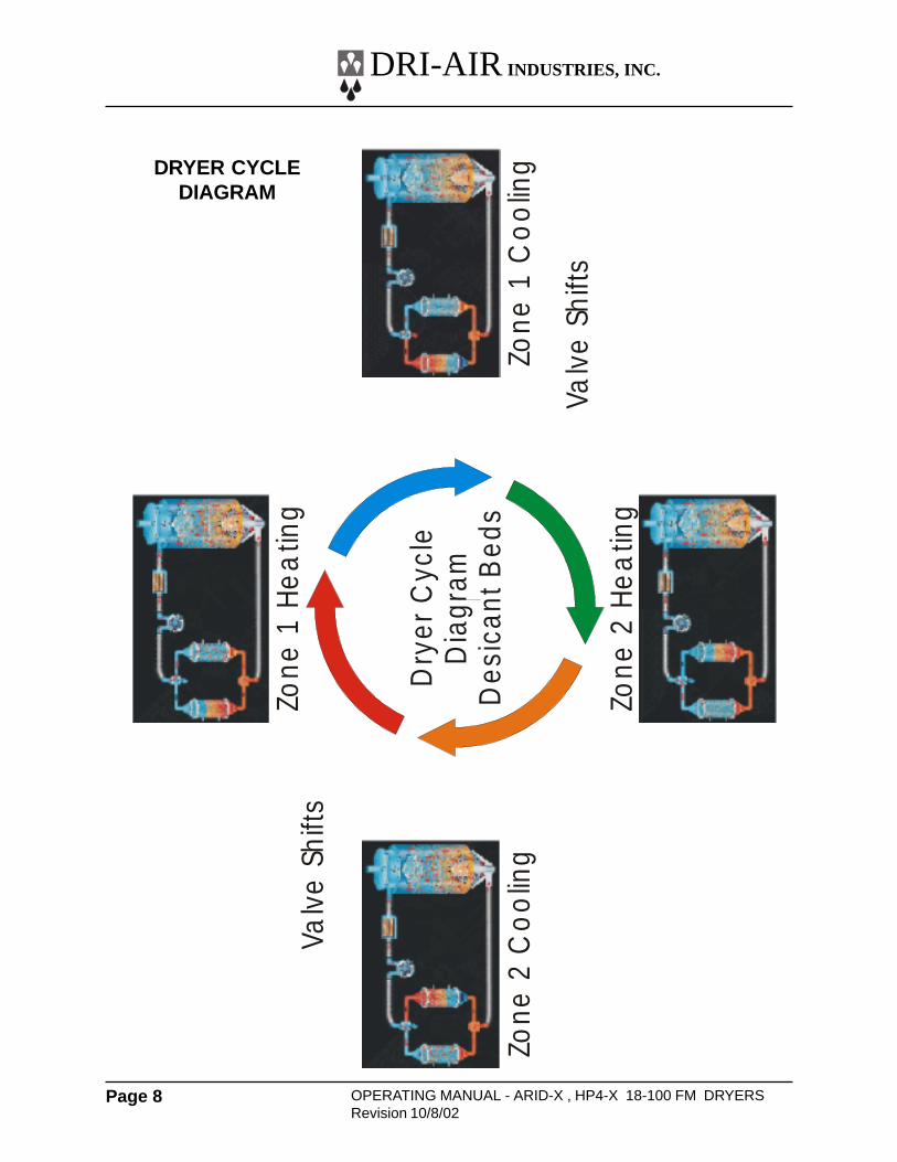
The ARID-X dryer series is a dual bed design that provides aconstant supply of dry air to the material hopper. While onebed is removing moisture from the process air the other isregenerating by heating the desiccant to a high temperature.Once the regenerated bed cools down, the Zone Valveswitches the airflow, and the newly regenerated bed is used todesiccate the process air stream. The saturated bed is nowregenerated in the same manner, completing the regenerationcycle. The cycle is depicted Page 8.
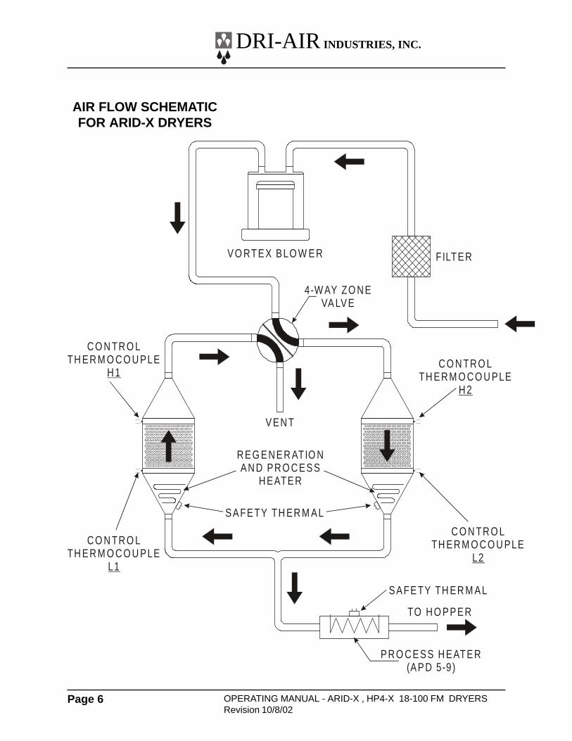
The airflow design of the ARID-X dryers makes theregeneration cycle more efficient because we utilize a smallamount of the desiccated process air rather than ambient airto regenerate the desiccant bed. This reduces the impact ofthe high moisture content of the ambient air, which wouldcontaminate the desiccant bed, and allows the dryer to attaina lower dew point. Please see the Air Flow Schematic onPage 6.
HP4-X Design
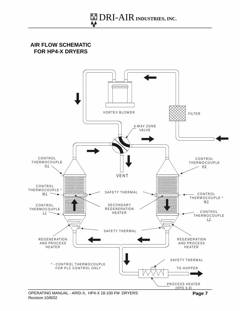
Our patented HP4-X design incorporates 4 desiccant bedswhere two are stacked, one over the other. This nearlydoubles the amount of desiccant available for drying theprocess air stream, and because of the tower design, thedryer is able to regenerate the desiccant in the same time asour ARID-X series. This allows the dryer to operate in veryhigh humidity conditions without affecting the process air dewpoint. In fact, this design produces dew point levels of – 40’ to-80’ C for faster more complete drying of your material. Pleasesee the Air FLow Diagram on Page 7.
Hopper Design
Dri-Air’s ”all stainless” hopper design utilizes a stainless steelinner shell surrounded by a stainless steel jacketed insulationlayer. The easily removable stainless steel spreader conepromotes proper material flow to ensure that the material isdried efficiently and no dried material is left at the hopperbottom that needs to be fed out prior to operating. You mustensure that your hopper is adequately sized for your usagerate and is kept filled, to ensure that you have sufficient time todry the material.
DRYER OPERATION/FEATURES
DRI-AIR INDUSTRIES, INC.
OPERATING MANUAL - ARID-X, HP4-X 18-100 FM DRYERSRevision 10/8/02
Page 5
Dryer Controls
The ARID-X series can be supplied with the standard PLCControl Module or the advanced Microprocessor ControlModule, while the HP4-X series is only available with theMicroprocessor Control Module.
The PLC Control module includes a PLC control board,display board, temperature controller and touch pad that isprogrammed for the drying cycle described above. Thecontroller, display board and touch pad indicate the machinestatus, alarms, set points and allow you to enter operationalsettings for the dryer. These are explained in more detail laterin this manual.
The Microprocessor Control Module is one of the mostsophisticated yet operator friendly controls on the market. Ithas many more features than the PLC control module thatprovide the operator with more control and operationalflexibility with the dryer. These features and the operatinginstructions are covered in detail in the MicroprocessorControl Instruction Manual included with your dryer.
DRYER OPERATION/FEATURES (Cont.)
DRI-AIR INDUSTRIES, INC.
OPERATING MANUAL - ARID-X , HP4-X 18-100 FM DRYERSRevision 10/8/02
Page 6
AIR FLOW SCHEMATICFOR ARID-X DRYERS
XX
VO RTEX BLO W ER
4-W AY ZO N EVA LVE
FILTER
VEN T
SAFETY TH ER M AL
SAFETY TH ER M AL
R EG EN ER ATIO NAN D PR O C ESS
H EATER
TO H O PPER
PR O C ESS H EATER(APD 5-9)
C O N TR O LTH ER M O C O U PLE
H 2
C O N TR O LTH ER M O C O U PLE
L1
C O N TR O LTH ER M O C O U PLE
L2
C O N TR O LTH ER M O C O U PLE
H 1
DRI-AIR INDUSTRIES, INC.
OPERATING MANUAL - ARID-X, HP4-X 18-100 FM DRYERSRevision 10/8/02
Page 7
AIR FLOW SCHEMATICFOR HP4-X DRYERS
XX
V O R TE X B L O W E R
4-W AY Z O N EVA LV E
F ILT E R
VE N T
C O N T R O LT H E R M O C O U P LE *
M 2
C O N T R O L T H E R M O C O U P LE *
M 1
S A F E TY T H E R M A L
S A F E TY T H E R M A L
S A F E TY T H E R M A L
R E G E N E R AT IO NA N D P R O C E S S
H E ATE R
R E G E N E R AT IO NA N D P R O C E S S
H E ATE R
TO H O P P E R
P R O C E S S H E AT E R(H P D 5 -9 )
S E C O N D A R YR E G E N E R AT IO N
H E ATE R
C O N T R O L T H E R M O C O U P LE
H 1
C O N T R O LT H E R M O C O U P LE
H 2
C O N T R O LT H E R M O C O U P LE
L2
C O N T R O L T H E R M O C O U P LE
L1
* - C O N T R O L T H E R M O C O U P L EF O R P L C C O N T R O L O N LY
DRI-AIR INDUSTRIES, INC.
OPERATING MANUAL - ARID-X , HP4-X 18-100 FM DRYERSRevision 10/8/02
Page 8
Dry
er C
ycle
Dia
gram
Des
ican
t Bed
s
Zone
1 H
ea
ting
Zone
2 C
oo
ling
Zone
2 H
ea
ting
Zone
1 C
oo
ling
Valv
e S
hifts
Valv
e S
hifts
DRYER CYCLEDIAGRAM
XX
DRI-AIR INDUSTRIES, INC.
OPERATING MANUAL - ARID-X, HP4-X 18-100 FM DRYERSRevision 10/8/02
Page 9
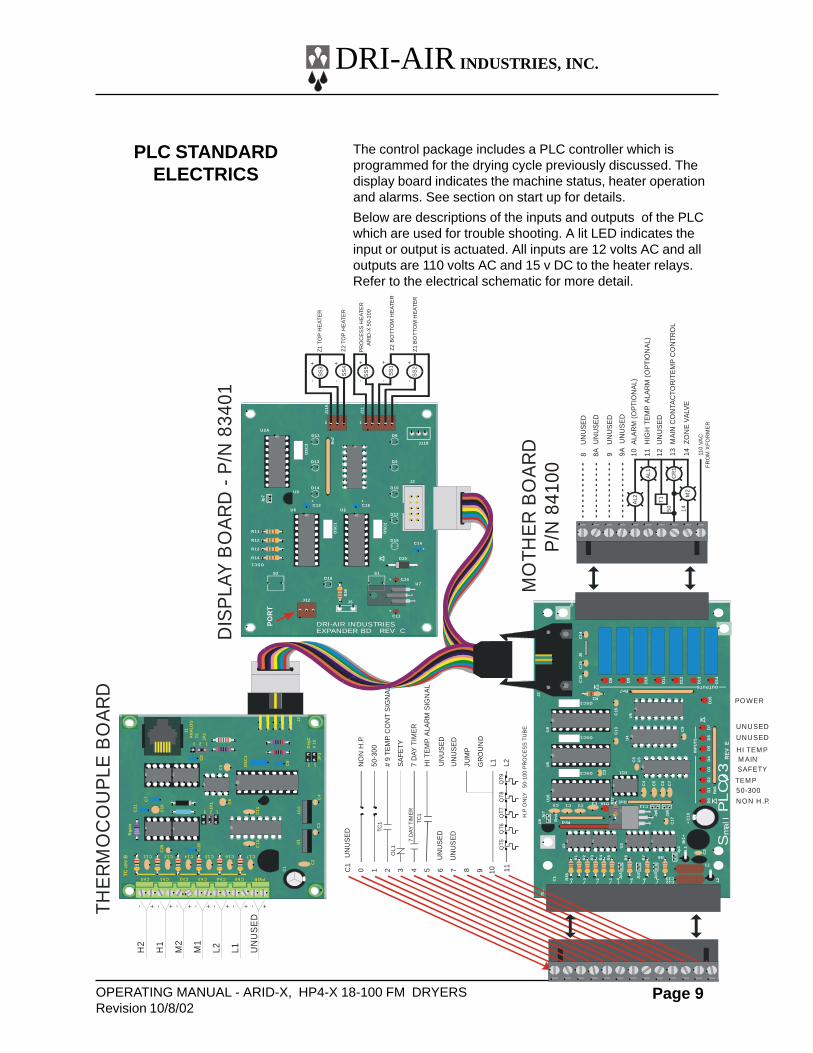
The control package includes a PLC controller which isprogrammed for the drying cycle previously discussed. Thedisplay board indicates the machine status, heater operationand alarms. See section on start up for details.
Below are descriptions of the inputs and outputs of the PLCwhich are used for trouble shooting. A lit LED indicates theinput or output is actuated. All inputs are 12 volts AC and alloutputs are 110 volts AC and 15 v DC to the heater relays.Refer to the electrical schematic for more detail.
PLC STANDARDELECTRICS
XX
S2
J12
D16
C11
C20
C14
C15C13
D20
D15
D12
D10D14
D9D13
D8D11
J5
Jp7
J2
1 1
J118
J11
J11A
U7
U5
U9
U2
U2A
S1
R36
OS
C1
OS
C3
OS
C2
Rn
7
OSC1
R11
R12
R13
R14
+
++
++
C18
C1
3
C16
D16
C12
Rn5
Rn
6
INP
UT
S
Rn7OUTPUTS
R37
R38
Tb
1
R1
R2
R3
R4
R5
R6
Jp1
Jp2
Jp3
Jp4
Jp6
Jp5
Br1
++
C1
8
C17
C22C23
L1
L2
Z1
C2
R7 R8
C11C0 C1 C2C3
C2
U3
U4
U6
C8
U11
C15
D8
D9
D0
D1
D2
D3
D4
D5
D6
D7
D1
0
D1
1
D1
2
D1
3
D1
4
D15
C4
C5
C6
C7
C9
C1
9J5
R2
OSC1
OSC3
OSC2
J2
U8
U9
U1
C1 0 1 2 3 5 6 74
U2
Jp7
Rn
4
Rn3
U5
U18
C1
4
Tb
2
Sm
all
PL
C0
3R
EV
E
8U
NU
SE
D
8AU
NU
SE
D
9U
NU
SE
D
9AU
NU
SE
D
10A
LAR
M(O
PTI
ON
AL)
11H
IGH
TEM
P.A
LAR
M(O
PTI
ON
AL)
12U
NU
SE
D
13M
AIN
CO
NTA
CTO
R/T
EM
PC
ON
TRO
L
14Z
ON
EV
ALV
E
PR
OC
ES
SH
EA
TER
AR
ID-X
50-1
00
Z1
TOP
HE
AT
ER
Z2
TOP
HE
ATE
R
TEM P
SAFETYM AINHI TEM P
PO WER
DIS
PLA
YB
OA
RD
-P
/N83
401
THE
RM
OC
OU
PLE
BO
AR
D
MO
THE
RB
OA
RD
PO
RT
DRI-AIR INDUSTRIESEXPANDER BD REV C
SS
4
AL2
CR
1
M2
AL1
SS
1
SS
2
110
VAC
FR
OM
XF
OR
ME
R
T1
50 14
UN
US
ED
NO
NH
.P.
50-3
00
#9
TEM
P.C
ON
TS
IGN
AL
SA
FETY
7D
AYTI
ME
R
HIT
EM
P.A
LAR
MS
IGN
AL
UN
US
ED
UN
US
ED
UN
US
ED
GR
OU
ND
L1 L2Q
T9Q
T8Q
T7Q
T6Q
T5
OL1
7D
AY
TIM
ER
H.P
ON
LY50
-100
PR
OC
ES
STU
BE
C1
0 1 2 3 4 5 6 7
C13 C14 C15 C16 C17
Ch5Ch4Ch3Ch2 PWRCh1Ch0
C3
C4
U1
U10
C2
C21
TCre
vB
Rga
in
C20
C19
C18
C9
J2
JP2
JP3
Deg
CX
10
OS
C1
JP1
AN
ALO
GTC
C8
J1
C7
C6
C1
C10
C11
C5
1
1
1
2
2
2
3
3
C12
- + - + - + - + - + - + - +
H2
H1
M2
M1
L2 L1 UN
US
ED
SS
3
SS
5
-
+-
+-
+++
--
Z1
BO
TTO
M H
EA
TER
Z2
BO
TTO
M H
EA
TER
UNUSED
UNUSED
50-300
NON H .P.
TC1
TC1
JUM
P
UN
US
ED
8 9 10 11
P/N
841
00
DRI-AIR INDUSTRIES, INC.
OPERATING MANUAL - ARID-X , HP4-X 18-100 FM DRYERSRevision 10/8/02
Page 10
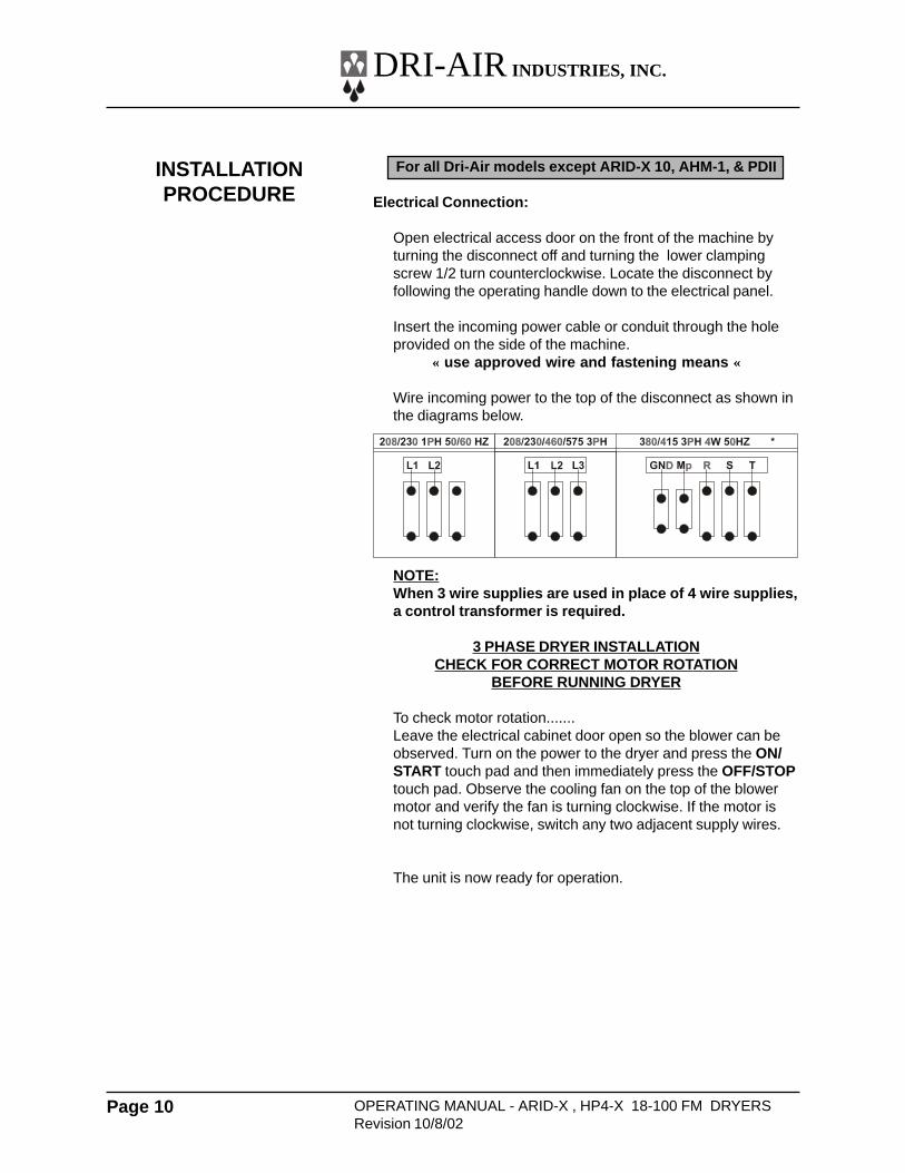
For all Dri-Air models except ARID-X 10, AHM-1, & PDII
Electrical Connection:
Open electrical access door on the front of the machine byturning the disconnect off and turning the lower clampingscrew 1/2 turn counterclockwise. Locate the disconnect byfollowing the operating handle down to the electrical panel.
Insert the incoming power cable or conduit through the holeprovided on the side of the machine.
« use approved wire and fastening means «
Wire incoming power to the top of the disconnect as shown inthe diagrams below.
NOTE:When 3 wire supplies are used in place of 4 wire supplies,a control transformer is required.
3 PHASE DRYER INSTALLATIONCHECK FOR CORRECT MOTOR ROTATION
BEFORE RUNNING DRYER
To check motor rotation.......Leave the electrical cabinet door open so the blower can beobserved. Turn on the power to the dryer and press the ON/START touch pad and then immediately press the OFF/STOPtouch pad. Observe the cooling fan on the top of the blowermotor and verify the fan is turning clockwise. If the motor isnot turning clockwise, switch any two adjacent supply wires.
The unit is now ready for operation.
INSTALLATIONPROCEDURE
XX
DRI-AIR INDUSTRIES, INC.
OPERATING MANUAL - ARID-X, HP4-X 18-100 FM DRYERSRevision 10/8/02
Page 11
Standard Electrics
Operating this unit is very simple. Once the dryer isconnected to the facility power supply, the unit can be startedby turning the disconnect located on the electrical panelenclosure to the ON position and pressing the ON button onthe Control Panel Key Pad. To shut the dryer off, simply pushthe OFF button on the Control Panel Key Pad and turn thedisconnect to the OFF position.
Setting the process air temperature is done using the DigitalController.
For a more detailed explanation, see the following sections.
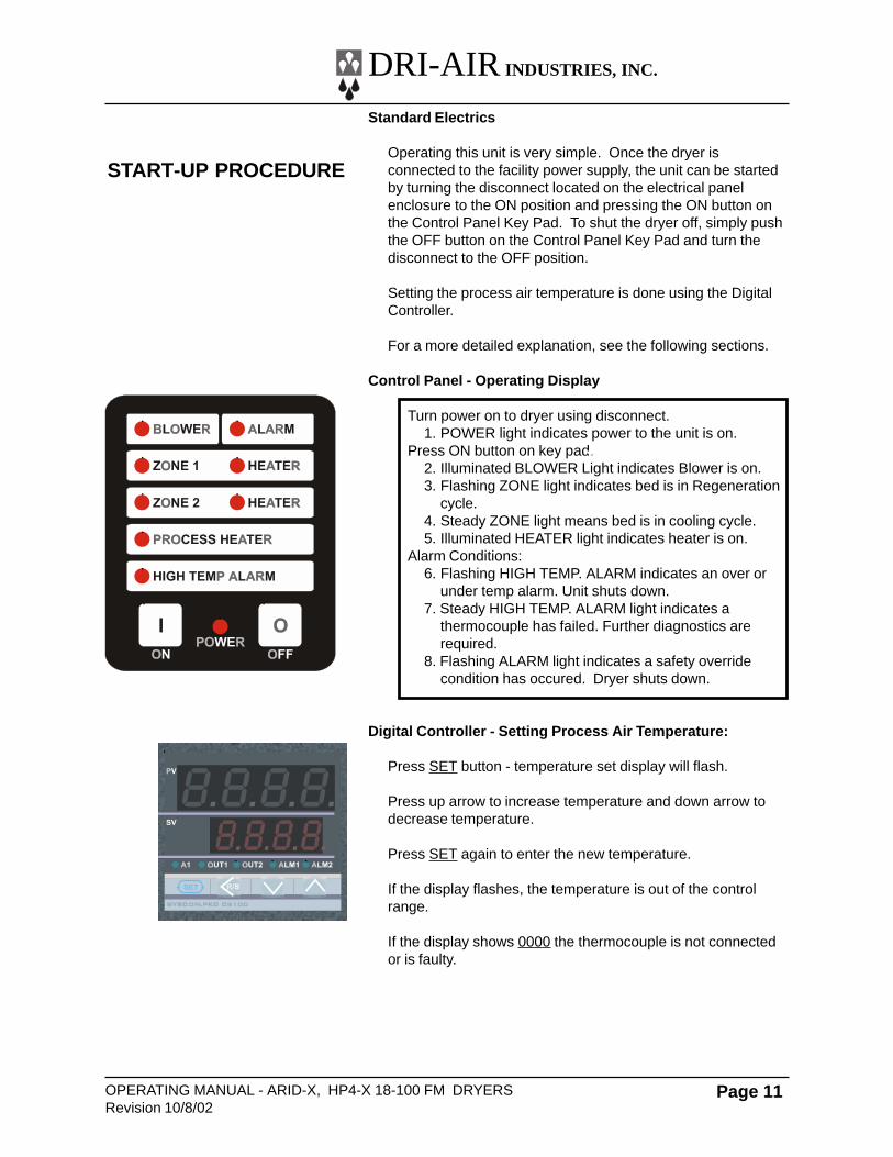
Control Panel - Operating Display
Turn power on to dryer using disconnect.1. POWER light indicates power to the unit is on.
Press ON button on key pad.2. Illuminated BLOWER Light indicates Blower is on.3. Flashing ZONE light indicates bed is in Regeneration
cycle.4. Steady ZONE light means bed is in cooling cycle.5. Illuminated HEATER light indicates heater is on.
Alarm Conditions:6. Flashing HIGH TEMP. ALARM indicates an over or
under temp alarm. Unit shuts down.7. Steady HIGH TEMP. ALARM light indicates a
thermocouple has failed. Further diagnostics arerequired.
8. Flashing ALARM light indicates a safety overridecondition has occured. Dryer shuts down.
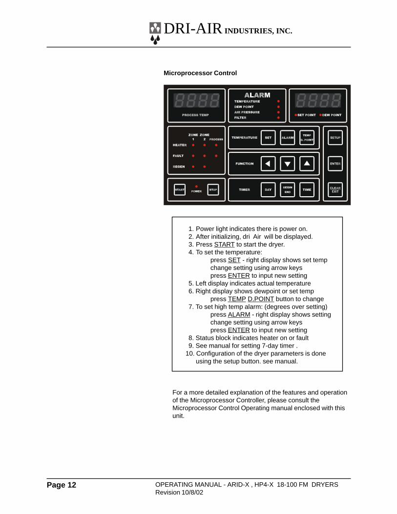
Digital Controller - Setting Process Air Temperature:
Press SET button - temperature set display will flash.
Press up arrow to increase temperature and down arrow todecrease temperature.
Press SET again to enter the new temperature.
If the display flashes, the temperature is out of the controlrange.
If the display shows 0000 the thermocouple is not connectedor is faulty.
START-UP PROCEDURE
XX
DRI-AIR INDUSTRIES, INC.
OPERATING MANUAL - ARID-X , HP4-X 18-100 FM DRYERSRevision 10/8/02
Page 12
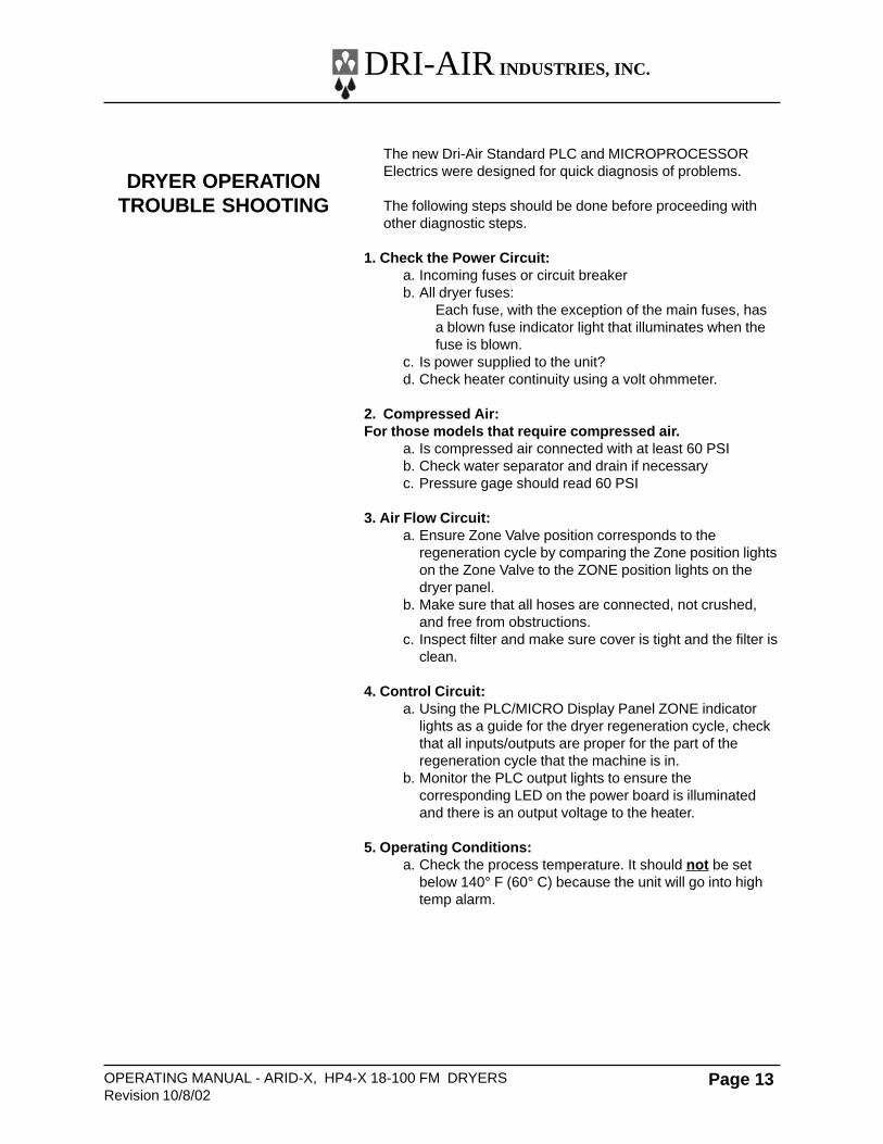
Microprocessor Control
1. Power light indicates there is power on.2. After initializing, dri Air will be displayed.3. Press START to start the dryer.4. To set the temperature:
press SET - right display shows set tempchange setting using arrow keyspress ENTER to input new setting
5. Left display indicates actual temperature6. Right display shows dewpoint or set temp
press TEMP D.POINT button to change7. To set high temp alarm: (degrees over setting)
press ALARM - right display shows settingchange setting using arrow keyspress ENTER to input new setting
8. Status block indicates heater on or fault9. See manual for setting 7-day timer .
10. Configuration of the dryer parameters is doneusing the setup button. see manual.
For a more detailed explanation of the features and operationof the Microprocessor Controller, please consult theMicroprocessor Control Operating manual enclosed with thisunit.
DRI-AIR INDUSTRIES, INC.
OPERATING MANUAL - ARID-X, HP4-X 18-100 FM DRYERSRevision 10/8/02
Page 13
The new Dri-Air Standard PLC and MICROPROCESSORElectrics were designed for quick diagnosis of problems.
The following steps should be done before proceeding withother diagnostic steps.
1. Check the Power Circuit:a. Incoming fuses or circuit breakerb. All dryer fuses:
Each fuse, with the exception of the main fuses, hasa blown fuse indicator light that illuminates when thefuse is blown.
c. Is power supplied to the unit?d. Check heater continuity using a volt ohmmeter.
2. Compressed Air:For those models that require compressed air.
a. Is compressed air connected with at least 60 PSIb. Check water separator and drain if necessaryc. Pressure gage should read 60 PSI
3. Air Flow Circuit:a. Ensure Zone Valve position corresponds to the
regeneration cycle by comparing the Zone position lightson the Zone Valve to the ZONE position lights on thedryer panel.
b. Make sure that all hoses are connected, not crushed,and free from obstructions.
c. Inspect filter and make sure cover is tight and the filter isclean.
4. Control Circuit:a. Using the PLC/MICRO Display Panel ZONE indicator
lights as a guide for the dryer regeneration cycle, checkthat all inputs/outputs are proper for the part of theregeneration cycle that the machine is in.
b. Monitor the PLC output lights to ensure thecorresponding LED on the power board is illuminatedand there is an output voltage to the heater.
5. Operating Conditions:a. Check the process temperature. It should not be set
below 140° F (60° C) because the unit will go into hightemp alarm.
DRYER OPERATIONTROUBLE SHOOTING
DRI-AIR INDUSTRIES, INC.
OPERATING MANUAL - ARID-X , HP4-X 18-100 FM DRYERSRevision 10/8/02
Page 14
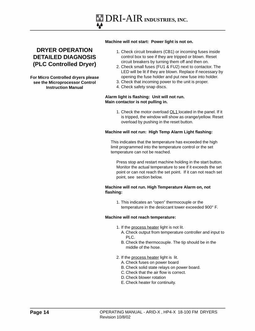
Machine will not start: Power light is not on.
1. Check circuit breakers (CB1) or incoming fuses insidecontrol box to see if they are tripped or blown. Resetcircuit breakers by turning them off and then on.
2. Check small fuses (FU1 & FU2) next to contactor. TheLED will be lit if they are blown. Replace if necessary byopening the fuse holder and put new fuse into holder.
3. Check that incoming power to the unit is proper.4. Check safety snap discs.
Alarm light is flashing: Unit will not run.Main contactor is not pulling in.
1. Check the motor overload OL1 located in the panel. If itis tripped, the window will show as orange/yellow. Resetoverload by pushing in the reset button.
Machine will not run: High Temp Alarm Light flashing:
This indicates that the temperature has exceeded the highlimit programmed into the temperature control or the settemperature can not be reached.
Press stop and restart machine holding in the start button.Monitor the actual temperature to see if it exceeds the setpoint or can not reach the set point. If it can not reach setpoint, see section below.
Machine will not run. High Temperature Alarm on, notflashing:
1. This indicates an “open” thermocouple or thetemperature in the desiccant tower exceeded 900° F.
Machine will not reach temperature:
1. If the process heater light is not lit.A. Check output from temperature controller and input to
PLC.B. Check the thermocouple. The tip should be in the
middle of the hose.
2. If the process heater light is lit.A. Check fuses on power boardB. Check solid state relays on power board.C.Check that the air flow is correct.D.Check blower rotationE. Check heater for continuity.
DRYER OPERATIONDETAILED DIAGNOSIS(PLC Controlled Dryer)
For Micro Controlled dryers pleasesee the Microprocessor Control
Instruction Manual
DRI-AIR INDUSTRIES, INC.
OPERATING MANUAL - ARID-X, HP4-X 18-100 FM DRYERSRevision 10/8/02
Page 15
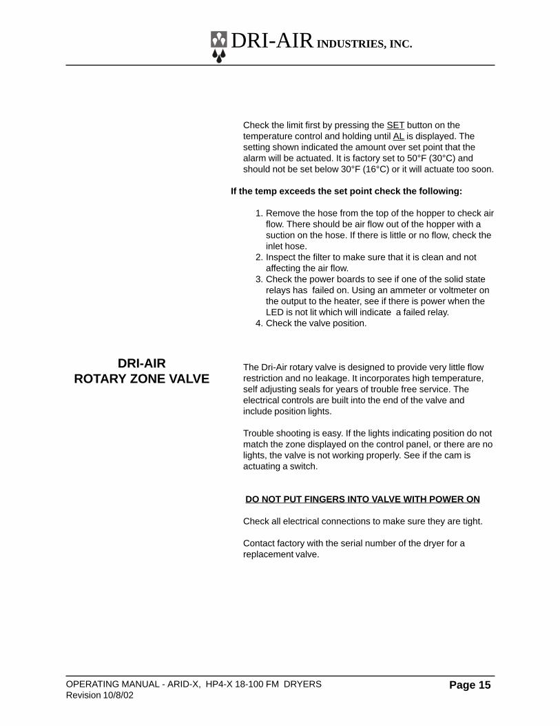
Check the limit first by pressing the SET button on thetemperature control and holding until AL is displayed. Thesetting shown indicated the amount over set point that thealarm will be actuated. It is factory set to 50°F (30°C) andshould not be set below 30°F (16°C) or it will actuate too soon.
If the temp exceeds the set point check the following:
1. Remove the hose from the top of the hopper to check airflow. There should be air flow out of the hopper with asuction on the hose. If there is little or no flow, check theinlet hose.
2. Inspect the filter to make sure that it is clean and notaffecting the air flow.
3. Check the power boards to see if one of the solid staterelays has failed on. Using an ammeter or voltmeter onthe output to the heater, see if there is power when theLED is not lit which will indicate a failed relay.
4. Check the valve position.
The Dri-Air rotary valve is designed to provide very little flowrestriction and no leakage. It incorporates high temperature,self adjusting seals for years of trouble free service. Theelectrical controls are built into the end of the valve andinclude position lights.
Trouble shooting is easy. If the lights indicating position do notmatch the zone displayed on the control panel, or there are nolights, the valve is not working properly. See if the cam isactuating a switch.
DO NOT PUT FINGERS INTO VALVE WITH POWER ON
Check all electrical connections to make sure they are tight.
Contact factory with the serial number of the dryer for areplacement valve.
DRI-AIRROTARY ZONE VALVE
DRI-AIR INDUSTRIES, INC.
OPERATING MANUAL - ARID-X , HP4-X 18-100 FM DRYERSRevision 10/8/02
Page 16
PARTS LISTS
GENERAL
ELECTRICAL
HEATERS
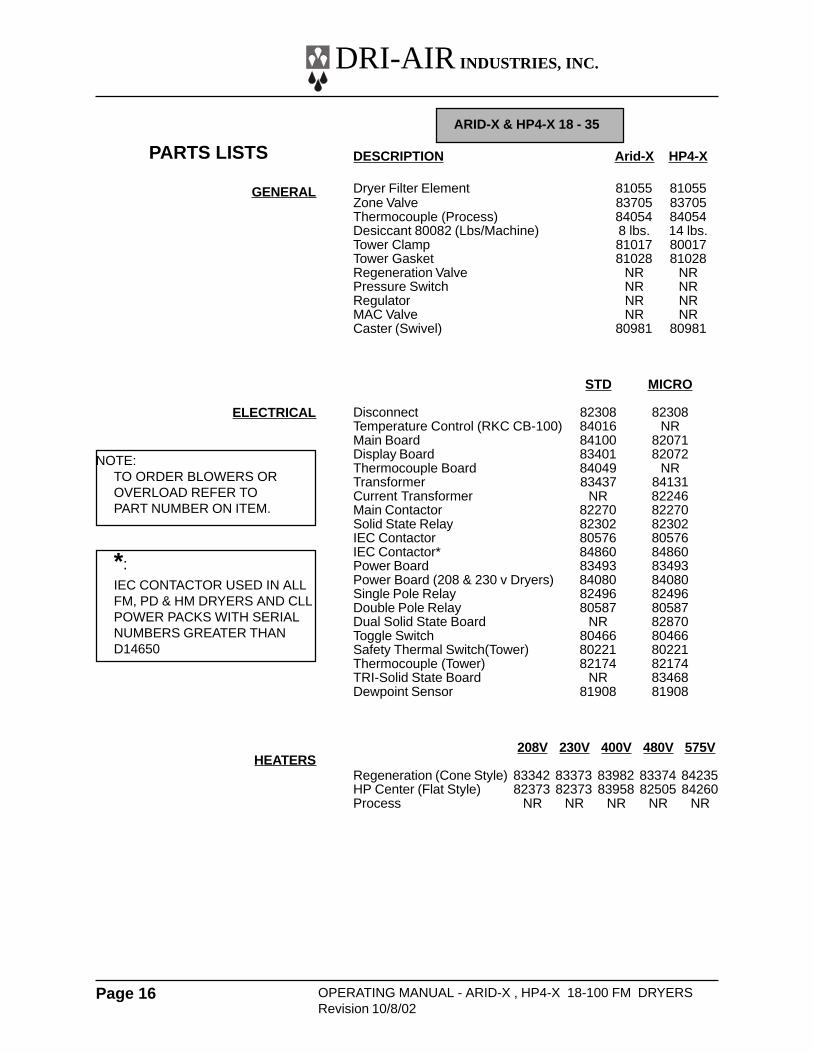
ARID-X & HP4-X 18 - 35
DESCRIPTION Arid-X HP4-X
Dryer Filter Element 81055 81055Zone Valve 83705 83705Thermocouple (Process) 84054 84054Desiccant 80082 (Lbs/Machine) 8 lbs. 14 lbs.Tower Clamp 81017 80017Tower Gasket 81028 81028Regeneration Valve NR NRPressure Switch NR NRRegulator NR NRMAC Valve NR NRCaster (Swivel) 80981 80981
STD MICRO
Disconnect 82308 82308Temperature Control (RKC CB-100) 84016 NRMain Board 84100 82071Display Board 83401 82072Thermocouple Board 84049 NRTransformer 83437 84131Current Transformer NR 82246Main Contactor 82270 82270Solid State Relay 82302 82302IEC Contactor 80576 80576IEC Contactor* 84860 84860Power Board 83493 83493Power Board (208 & 230 v Dryers) 84080 84080Single Pole Relay 82496 82496Double Pole Relay 80587 80587Dual Solid State Board NR 82870Toggle Switch 80466 80466Safety Thermal Switch(Tower) 80221 80221Thermocouple (Tower) 82174 82174TRI-Solid State Board NR 83468Dewpoint Sensor 81908 81908
208V 230V 400V 480V 575V
Regeneration (Cone Style) 83342 83373 83982 83374 84235HP Center (Flat Style) 82373 82373 83958 82505 84260Process NR NR NR NR NR
NOTE:TO ORDER BLOWERS OROVERLOAD REFER TOPART NUMBER ON ITEM.
*:IEC CONTACTOR USED IN ALLFM, PD & HM DRYERS AND CLLPOWER PACKS WITH SERIALNUMBERS GREATER THAND14650
DRI-AIR INDUSTRIES, INC.
OPERATING MANUAL - ARID-X, HP4-X 18-100 FM DRYERSRevision 10/8/02
Page 17
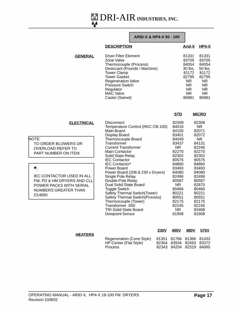
ARID-X & HP4-X 50 - 100
DESCRIPTION Arid-X HP4-X
Dryer Filter Element 81331 81331Zone Valve 83705 83705Thermocouple (Process) 84054 84054Desiccant (Pounds / Machine) 30 lbs. 50 lbs.Tower Clamp 81172 81172Tower Gasket 82795 82795Regeneration Valve NR NRPressure Switch NR NRRegulator NR NRMAC Valve NR NRCaster (Swivel) 80981 80981
STD MICRO
Disconnect 82308 82308Temperature Control (RKC CB-100) 84016 NRMain Board 84100 82071Display Board 83401 82072Thermocouple Board 84049 NRTransformer 83437 84131Current Transformer NR 82246Main Contactor 82270 82270Solid State Relay 82302 82302IEC Contactor 80576 80576IEC Contactor* 84860 84860Power Board 83493 83493Power Board (208 & 230 v Dryers) 84080 84080Single Pole Relay 82496 82496Double Pole Relay 80587 80587Dual Solid State Board NR 82870Toggle Switch 80466 80466Safety Thermal Switch(Tower) 80221 80221Safety Thermal Switch(Process) 80551 80551Thermocouple (Tower) 82175 82175Transformer .050 82245 82245TRI-Solid State Board NR 83468Dewpoint Sensor 81908 81908
230V 400V 480V 575V
Regeneration (Cone Style) 81351 81766 81366 81432HP Center (Flat Style) 82364 83934 82493 83372Process 82343 84204 82319 84065
GENERAL
ELECTRICAL
HEATERS
NOTE:TO ORDER BLOWERS OROVERLOAD REFER TOPART NUMBER ON ITEM.
*:IEC CONTACTOR USED IN ALLFM, PD & HM DRYERS AND CLLPOWER PACKS WITH SERIALNUMBERS GREATER THAND14650

DRI-AIR INDUSTRIES, INC.
OPERATING MANUAL - ARID-X , HP4-X 18-100 FM DRYERSRevision 10/8/02
Page 18
NOTES:
DRI-AIR INDUSTRIES, INC.
OPERATING MANUAL - ARID-X, HP4-X 18-100 FM DRYERSRevision 10/8/02
Page 19
NOTES:
DRI-AIR INDUSTRIES, INC.
OPERATING MANUAL - ARID-X , HP4-X 18-100 FM DRYERSRevision 10/8/02
Page 20
NOTES: