Aria - oxworks-web-files.s3-ap-southeast-2.amazonaws.com
28
Aria Instructions and warnings for installation and use Swing Gate Motor
Transcript of Aria - oxworks-web-files.s3-ap-southeast-2.amazonaws.com

Aria
Instructions and warnings for installation and use
Swing Gate Motor

II
ARIA200MARIA400M
ECCO5BOPH200
1
step Apag. I - 2
step Bpag. I - 2
step Cpag. VIII - 6
step Dpag. 6
step Epag. 6
CLB202CLB203

III
CLB202CLB203
PH200PH200 PH200PH200
ARIA200ARIA400
ARIA200ARIA400
AC
C
DD
B
2Step A
A B C D = See Table 2 (Par. 3.4)
3Step B 01.
02.
04.
302
846
9890
320 > 100 mm
100 > 250 mm
➠
B C
A
740 / 775 mm
740mm
775mm
03.• Table 1 •
A 160B 240 100° A 205
B 180 110° A 160B 240 95° A 115
B 290 90°
A 180B 220 95° A 200
B 190 105° A 150B 250 95° A 110
B 325 90°
A 190B 200 95° A 190
B 210 100° A 140B 260 95°
A 200B 180 95° A 180
B 220 100° A 130B 270 90°
A 210B 160 95° A 170
B 230 95° A 125B 280 90°

IV
➠
➠
740mm
23
4
1
05.
06.
S2
1
2
3
1
3
07.
08.
V
➠ 09.
2
180°
3
1
10.
740mm
1
23
11.
12.1
2
180°3

VI
PH200 Installation of photocells > Fig. 5 - Paragraph 3.6
Installation of flashing light > Fig. 6 - Paragraph 3.7FL200
1
2
4
03.
01. 02.

VII
5
1
Led SAFE
3
2
4
Ø < 5 mm
PH200
01.
03.
05.
02.
04.

VIII
6
Ø = 6 mm
x4
05. B
Ø = 6 mm
x4
05. A
2
1
01. 02. 03. 04.
(aerial)(flash)
2
1
06. 07. 08. 09.
FL200

IX
After having connected all the components of the kit and before closing the cover of the gearmo -tor (Fig. 8), it is possible to connect other com -ponents designed for the system (optional and not present in the package) .
1
2
8
Step CTX RX
M M M M FLASH BUS STOP
M1
M2
Flas
h
ECSb
us
Stop
SbS
Aeria
l
SbS
F 2AF
NCNO
led ECSbus
led Stop
led SbS
M1M2
* brown
** yellow
***
*
*
*
**
**
**
***
***
***
7
blue

X
To start-up the system, see Chapter 5.
Step D
Step E
To PROGRAMME the system, see Chapter 6.
➡➡

English – 1
Eng
lish
CONTENTS
QUICK GUIDE (images only) II-X1 GENERAL WARNINGS: SAFETY - INSTALLATION - USE 42 PRODUCT DESCRIPTION AND INTENDED USE 43 INSTALLATION 4
3.1 VERIFYING THE SUITABILITY OF THE GATE AND ENVIRONMENT 43.2 VERIFYING THE PRODUCT’S APPLICATION LIMITS 43.3 PRODUCT TECHNICAL SPECIFICATIONS 43.4 PRE-INSTALLATION WORKS 53.5 INSTALLING THE ARIA GEARMOTORS (models 400C/600C) and CLB CONTROL UNIT (models 202/203) 63.5.1 INSTALLING THE ARIA GEARMOTORS 200M/400M 63.5.2 INSTALLING THE CLB202/203 CONTROL UNIT 63.6 INSTALLING THE PHOTOCELLS model PH200 63.7 INSTALLING THE FLASHING LIGHT model FL200 6
4 ELECTRICAL CONNECTIONS 74.1 ELECTRICAL CONNECTION TO THE CONTROL PANEL 74.2 POWER SUPPLY CONNECTION 7
5 PROGRAMMING 75.1 CONTROL UNIT KEYS 75.2 INITIAL CHECKS 75.3 MEMORISATION OF CONNECTED DEVICES 75.4 MEMORISATION OF GATE LEAF OPENING AND CLOSING ANGLES 85.5 MEMORISATION OF THE 1ST TRANSMITTER 85.6 BASIC ADJUSTMENTS 95.6.1 Choosing the gate leaf manoeuvre speed 95.6.2 Choosing the operating cycle of the gate leaf manoeuvre 9
6 TESTING AND COMMISSIONING 106.1 TESTING 106.2 COMMISSIONING 10
7 MAINTENANCE 108 PRODUCT DISPOSAL 109 FURTHER INFORMATION 11
9.1 ADVANCED ADJUSTMENTS 119.1.1 Adjusting the parameters using the transmitter 119.1.1.1 Parameter adjustment procedure: Pause time - Pedestrian opening - Motor force - Step-by-Step function 119.1.1.2 Parameter adjustment procedure: SbS input configuration - Flash output configuration - Discharging of Motor 1
and 2 upon closing - Discharging of Motor 1 and 2 upon opening12
9.1.2 Verifying the values set for each parameter (using the transmitter) 129.1.2.1 Parameter verification procedure: Pause time - Pedestrian opening - Motor force - Step-by-Step Function 129.1.2.2 Parameter verification procedure: Discharging of Motor 1 upon closing - Discharging of Motor 1 upon opening -
Discharging of Motor 2 upon closing - Discharging of Motor 2 upon opening12
9.2 ADDING OR REMOVING DEVICES 139.2.1 Memorising additional devices 139.3 MEMORISING ADDITIONAL TRANSMITTERS 139.3.1 Mode 1 memorisation procedure 139.3.2 Mode 2 memorisation procedure 139.3.3 Memorisation procedure near the control unit with two transmitters 139.4 DELETING THE MEMORY OF THE INDIVIDUAL TRANSMITTER FROM THE CONTROL UNIT’S MEMORY 149.5 COMPLETE DELETION OF THE RADIO MEMORY 149.6 INSTALLING THE BACK-UP BATTERY 149.7 INSTALLING THE SOLAR POWER SYSTEM KIT model SOLEKIT 149.8 DIAGNOSTICS AND DEVICE SIGNALS 149.8.1 Photocell signals 149.8.2 Flashing light signals 149.8.3 Control unit signals 149.9 SPECIFICATIONS 169.9.1 ECSbus system 169.9.2 Stop input 169.9.3 Product durability 16
10 TROUBLESHOOTING 17EC Declaration of Conformity 18
11 USER GUIDE (to be delivered to the end user) (detachable insert) AANNEX I (detachable insert) B

English – 3
Eng
lish
1 GENERAL WARNINGS: SAFETY - INSTALLATION - USE (original instructions in Italian)
CAUTION Important safety instructions. Observe all the instructions as improper installation may cause serious damageCAUTION Important safety instructions. It is important to comply with these instructions to ensure personal safety. Store these
instructions• Before commencing the installation, check the “Product technical specifications”, in particular whether this product is suitable for automating your
guided part. Should it be unsuitable, DO NOT proceed with the installation• The product cannot be used before it has been commissioned as specified in the “Testing and commissioning” chapterCAUTION According to the most recent European legislation, the implementation of an automation system must comply with the
harmonised standards set forth in the Machinery Directive in force, which allow for declaring the presumed conformity of the automation. On account of this, all operations regarding connection to the mains electricity, as well as product testing, commissioning and maintenance, must be performed exclusively by a qualified and skilled technician!
• Before proceeding with the product’s installation, check that all materials are in good working order and are suitable for the intended applications• The product is not intended for use by persons (including children) with reduced physical, sensory or mental capacities, nor by anyone lacking suf-
ficient experience or familiarity with the product• Children must not play with the appliance• Do not allow children to play with the control devices of the product. Keep the remote controls out of reach of childrenCAUTION In order to avoid any danger from inadvertent resetting of the thermal cut-off device, this appliance must not be powered through an
external switching device, such as a timer, or connected to a supply that is regularly powered or switched off by the circuit• Provide a disconnection device (not supplied) in the plant’s mains power supply, with a contact opening distance that ensures complete disconnec-
tion under the conditions envisaged by Overvoltage Category III• Handle the product with care during installation, taking care to avoid crushing, knocks, falls or contact with liquids of any kind. Keep the product
away from sources of heat and open flames. Failure to observe the above can damage the product and increase the risk of danger or malfunctions.If this should happen, stop installation immediately and contact the Customer Service
• The manufacturer assumes no liability for damage to property, items or persons resulting from non-compliance with the assembly instructions. Insuch cases the warranty does not cover material defects
• The weighted sound pressure level of the emission A is lower than 70 dB(A)• Cleaning and maintenance to be carried out by the user must not be effected by unsupervised children• Before intervening on the system (maintenance, cleaning), always disconnect the product from the mains power supply• Check the system periodically, in particular all cables, springs and supports to detect possible imbalances, signs of wear or damage. Do not use if
repairs or adjustments are necessary, because a failure with the installation or an incorrectly balanced automated system may lead to injury• The packaging materials of the product must be disposed of in compliance with local regulations• Keep persons away from the gate when it is moved through the control elements• When performing a manoeuvre, keep an eye on the automated mechanism and keep all bystanders at a safe distance until the movement has been
completed• Do not operate the automation if anyone is working on it; disconnect the power supply before permitting any work to be carried out
INSTALLATION PRECAUTIONS
• Prior to installing the drive motor, check that all mechanical components are in good working order and properly balanced, and that the automationmoves correctly
• If the gate being automated has a pedestrian door, the system must include a control device inhibiting the operation of the motor when the pedestrian door is open
• Make sure that the controls are kept at a safe distance from moving parts, while allowing a good view of these.Unless a selector is used, the controls should be installed at least 1.5 m from the ground and must not be accessible
• If the opening movement is controlled by a fire-prevention system, make sure that any windows larger than 200 mm are closed by the control ele-ments
• Prevent and avoid any form of trapping between the moving and fixed parts during manoeuvres• Permanently affix the manual operation label next to the element enabling the manoeuvre itself• After installing the drive motor, make sure that the mechanism, protective system and all manual manoeuvres operate properly

4 – English
Eng
lish
The devices of this kit and other optional accessories belong to the Nice Home automation system and are designed to automate a swinging gate for residential use.
CAUTION! – Any use other than that specified herein or in environmental conditions other than those stated in this manual is to be con-sidered improper and is forbiddenThe kit comprises two electromechanical gearmotors with 24 V direct current; they are equipped with a key-operated mechanical release mechanism that allows for manually moving the gate in case of a power outage.A command control unit is included that manages the operation of the entire automation. The control unit is connected to the gearmotors and to the various devices occurs through the ECSbus system (a single cable with 2 wires).The control unit can be powered by fixed mains power (230 V ) or, alternatively, through the SOLEKIT photovoltaic system of the Nice Home range. If powered from the mains, it can be fitted with a back-up battery (mod. PR100, optional accessory) which ensures that the automation can execute a certain number of manoeuvres during the hours following a power outage.
2 PRODUCT DESCRIPTION AND INTENDED USE
3 INSTALLATION
Certain devices and accessories mentioned in this manual are optional and not included in the kit. The end stops are not included in the kit and do not belong to the Nice Home range of products.
Consult the Nice Home product catalogue or visit the website www.niceforyou.com
3.1 - VERIFYING THE SUITABILITY OF THE GATE AND ENVIRONMENT• Ensure that the mechanical structure of the gate is suitable for automation and complies with local standards; consult the technical data appearing on
the gate’s label. This product cannot automate a gate that is not already secure and efficient; moreover, it cannot resolve defects caused by improper installation of the gate or poor maintenance of the latter.
• Manually move the gate leaves in the two directions (open/closed) and make sure that the movement takes place with a constant friction at everypoint along its course (there should be no points requiring more nor less effort).
• If a gate leaf includes an access door, make sure that it does not obstruct normal gate movement; mount a suitable interlock system if necessary.• Manually bring the door of the gate into any position then leave it closed and make sure that it does not move.• Check that there is sufficient space where the gearmotors are installed to allow for effecting a manual release manoeuvre.• Check that the installation surfaces of the various devices are solid for guaranteeing a stable anchorage and that they are protected and guarded
against accidental knocks. For the photocells, choose a flat surface capable of guaranteeing proper alignment of the pair (Tx and Rx).
3.2 - VERIFYING THE PRODUCT’S APPLICATION LIMITSBefore proceeding with the installation, carry out the following checks and verify the ‘Product technical characteristics’ (Paragraph 3.3):• Check that the estimated durability is compatible with the intended use (Paragraph 9.9.3).• Ensure that all limitations, conditions and warnings appearing in this manual can be fully observed.
3.3 - PRODUCT TECHNICAL SPECIFICATIONS
Model type ARIA200M ARIA400M
Product type Electromechanical gearmotor for automation of automatic gates and doors
Technology adopted A 24 V motor , reducer with helical gears; mechanical release mechanism.
Maximum inrush torque 1230 Nm 1400 Nm
Nominal torque 300 Nm 300 Nm
Speed (no load) 20 mm/s 16 mm/s
Nominal torque speed 17 mm/s 14 mm/s
Maximum frequency of cycles 15 cycles/hour 15 cycles/hour
Maximum continuous operating time 4 minutes 4 minutes
Application limits Its structural characteristics make it suitable for use on gates weighing up to 250 kg and for gate leaves up to 2.5 m long.
Its structural characteristics make it suitable for use on gates weighing up to 450 kg and for gate leaves up to 4.5 m long.
Maximum power input 24 W 24 W
Ambient operating temperature -20°C ... +50°C
Protection rating IP44
Dimensions / weight 846 x 98 h 90 mm / 5 kg
Model type CLB202 CLB203
Product type Control unit for 1 or 2 24 V motors for automation of automatic gates or doors, inclusive of radio receiver for ECCO5... transmitters
Technology adopted Electronic board governed by an 8 Bit microcontroller with flash technology.A transformer inside the control unit, but separated from the board, reduces the mains voltage to the nominal 24V voltage used in all of the automation system
Mains power supply 230 V (+10% –15%) 50/60 Hz
Rated power input 100 W; inrush power is 300 W for a maximum duration of 2 s
Emergency power supply Configured for model PR100 back-up batteries
Flashing light output For flashing lights with 12 V lamp, maximum 21 W and EL100 interface connection
Step A Step B

English – 5
Eng
lish
ECSbus output An output with a maximum load of 15 ECSbus units (1 ECSbus unit is equal to the consumption of a pair of photocells)
SbS input For normally open contacts (closing of the contact triggers the Step-by-Step command)
Stop input For normally open contacts and/or for 8.2 kΩ constant resistance, or normally closed contacts with self-recognition of the “normal” status (any variation from the memorised status triggers the Stop command)
Radio aerial input 50Ω for RG58 or similar type of cable
Max. cable length Mains power supply: 30 m; inputs/outputs: 20 m with antenna cable preferably shorter than 5 m (observe the warnings regarding minimum gauge and type of cables)
Ambient operating temperature -20°C ... +55°C
Assembly Vertical, wall-mounted
Protection rating IP44
Dimensions / weight 180 x 240 h 110 mm / 2.8 kg
Possibility of remote control Using ECCO5... transmitters, the control unit is able to receive one or more of the following commands: Step-by-Step (SbS) - Partial Open - Open Only - Close Only
Memory capacity Up to 250 transmitters, if memorised in Mode 1 - 250 keys if memorised in Mode 2
ECCO5... transmitter range From 50 to 100m. This range can vary if there are obstacles or electromagnetic disturbances, and is affected by the position of the receiving aerial incorporated in the flasher
Programmable functions “Cycle” or “Complete cycle” (automatic closure) operation“Slow” or “fast” motor speedsPause time during “complete cycle”, selectable from 10, 20, 40, 80 secondsPartial open type selectable in 4 modesObstacle detection system motor force, with 4 selectable levelsStep-by-Step (SbS) command operation selectable in 4 modes
Self-programmed functions Auto-detection of devices connected to the ECSbus outputAuto-detection of the type of Stop device (NO or NC contact or 8.2 kΩ resistor)Auto-detection of the opening angles of each gate leafAutomation auto-detection with 1 or 2 motors
Note: in order to improve its products, NICE S.p.A. reserves the right to modify their technical specifications at any time without prior notice. In any case, the manufacturer guarantees their functionality and suitability for their intended use. Note: all technical specifications refer to a temperature of 20°C.
3.4 - PRE-INSTALLATION WORKSConsult Fig. 2 to define the approximate installation position of each device mounted on the system; the various elements are positioned according to a standard and customary layout.
Get all the tools and equipment required to complete the job; check that they are in good condition and that they conform to the local safety provisions.
Laying of electrical cables:01. Observe Fig. 2 to understand how the various devices should be connected to the control unit and which terminals should be used for each con-
nection. Only devices adopting the same technology can be connected to the ECSbus.
The ECSbus system allows for connecting multiple devices together using – between one device and the next – a single “bus” cable, with 2 internalelectrical conductors.
The connection between the devices can have a “cascade”, a “star” or a “mixed” configuration, between the first two.
cascade star combined
02. Observe Fig. 2 to understand how to position the electrical cables in the environment (it is advisable to draw on paper a similar layout, adapting itto the relevant requirements).
03. Read Table 2 to determine the type of cables to be used: each cable must not exceed the stated maximum length.
TABLE 2 - Types of electrical cables (see Fig. 2)Connection Type of cable Maximum admissible length
A 230 VAC 50/60 Hz power supply 3 x 1.5 mm2 (not supplied) 30 m *
B Flash flashing light output 2 x 0.5 mm2 20 mC Radio aerial RG58-type shielded cable 20 m (recommended < 5 m)D ECSbus Input / Output 2 x 0.5 mm2 20 m **E Stop input 2 x 0.5 mm2 20 m **F SbS (Step-by-Step) input 2 x 0.5 mm2 20 m **G Motors M1 and M2 output 3 x 1 mm2 10 m
* it is possible to use a power cable longer than 30 m, provided that it has a larger gauge (for example, 3 x 2.5 mm2) and is equipped with anearthing device, near the automation.
** For the ECSbus (1) cables and the Stop and SbS inputs, it is also possible to use a single cable with multiple internal conductors, to group multiple connections: for example, the Stop and SbS inputs can be connected to the KS100 selector with a cable measuring 4 x 0.5 mm2.
(1) CAUTION! – The ECSbus cables must be positioned in different raceways with respect to the motor cables.CAUTION! – The cables used must be suited to the installation environment; for example a cable of type H03VV-F for indoor envi-ronments, or type H07RN-F for outdoor environments.

6 – English
Eng
lish
3.5 - INSTALLING THE ARIA GEARMOTORS model 200M/400M and CONTROL UNIT model CLB 202/203
• All installation operations must be made with the system disconnected from the power supply. If the back-up battery is present, itmust be disconnected• Incorrect installation may cause serious physical injury to those working on or using the system.• Prior to starting, carry out the pre-installation checks stated under Paragraph 3.1.• For the system’s correct operation, it is necessary to include mechanical stops (not provided with the kit) on the ground or wall,positioned at the maximum opening and closing points of the gate leaf.
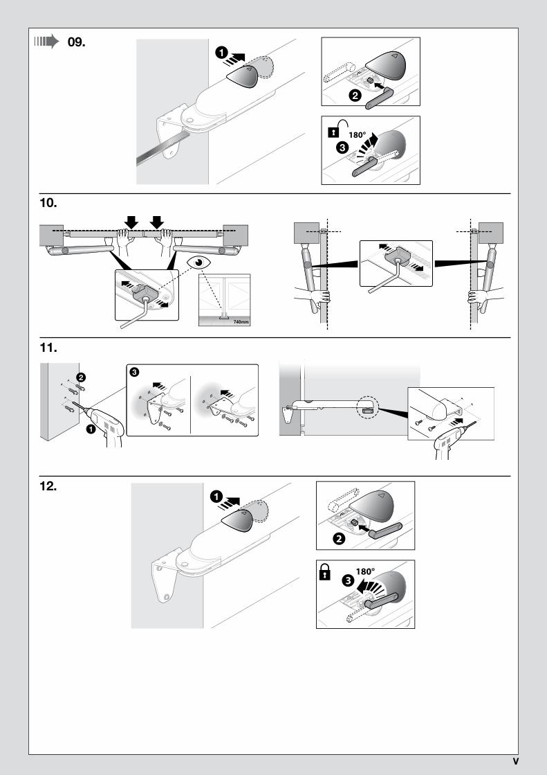
3.5.1 - INSTALLING THE ARIA GEARMOTORS 200M/400M01. Verify the gearmotor’s overall dimensions (Phase 01 - Fig. 3).
02. Choose the direction of the bracket to be used based on position “C” (Phase 02 - Fig. 3).
03. Choose position “A” in Table 1 (Phase 03 - Fig. 3).
04. Choose the installation position of the front and rear brackets, then temporarily fasten the rear bracket (Phase 04 - Fig. 3). Check that the sup-porting surface is solid.
05. If there is no closing stop on the ground, insert the closing limit switch as shown in Phase 05 - Fig. 3.
06. Fasten the gearmotor to the front bracket (Phase 06 - Fig. 3).
07. Position the gearmotor on the rear bracket and secure it with the washer, screw and nut (Phase 07 - Fig. 3).
08. Move the gearmotor until the front bracket rests against the gate leaf, then lock the latter temporarily (Phase 08 - Fig. 3).
09. Manually release the gearmotor (Phase 09 - Fig. 3).
10. Manually perform a few gate leaf opening and closing manoeuvres: check that the nut slides without any particular friction along the gearmotor’srolled ball screw. If necessary, adjust the gearmotor’s limit switch by loosening it with the appropriate Allen key and shifting it to the desired position(Phase 10 - Fig. 3).
13. Fasten the brackets permanently on the basis of the type and material of the gate leaf/column (Phase 11 - Fig. 3).
12. Manually lock the gearmotor (Phase 12 - Fig. 3).
14. Repeat the entire operation for the other gearmotor.
3.5.2 - INSTALLING THE CLB 202/203 CONTROL UNIT01. Install the control unit in an area protected against potential impacts and close to the gate, in order to reduce the overall length of the cables02. Remove the cover by prying with a screwdriver on the opening at the bottom; slide it a few centimetres then lift it from the bottom (Phase 01 - Fig.
5)03. Lay the duct for routing the electric cables so that they can be inserted from the lower section of the control unit04. Drill a hole in the bottom of the control unit and use suitable fittings to fasten the cable ducts (Phase 02 - Fig. 5)05. Open two holes on the bottom using a screwdriver and mark the drilling points using the bottom for reference; next, drill the wall using a percussion
drill with 6 mm bit and insert 6 mm wall plugs. Lastly, fasten the bottom with the relative screws (Phase 03 - Fig. 5)06. Before closing the control unit, make the electrical connections: see Chapter 4 and Fig. 707. To close the cover see Fig. 8.
At this point, it is possible to install the accessories pertaining to the system: for photocells PH200 > Par. 3.6 (Fig. 6) - for flashing light FL200 > Par. 3.7 (Fig. 7). For other optional accessories, consult the respective instruction manuals.
3.6 - INSTALLING THE PHOTOCELLS model PH200 (Fig. 5)
• position each photocell 40/60 cm above the ground • position them on the opposite sides of the zone to be protected • positionthem as close as possible to the gate (maximum distance = 15 cm) • a tube for passing the cables must be present in the fastening point • orient the TX transmitter towards the central zone of the RX receiver (allowed misalignment: maximum 5°)For the installation procedure see Fig. 5.
3.7 - INSTALLING THE FLASHING LIGHT model FL200 (Fig. 6)
• The flashing light must be positioned near the gate in a clearly visible position. It can be fasted to a horizontal or vertical surface.• For connection to the Flash terminal, no polarity needs to be observed; instead for connection of the shielded aerial cable, it is necessary to connectthe cable and sheath as shown in Fig. 7.
Choose the most suitable position in which to install the flashing light: it must be positioned near the gate in a clearly visible position. It can be fasted to a horizontal or vertical surface.
For the installation procedure see Fig. 6.
PH200
FL200

English – 7
Eng
lish
4 ELECTRICAL CONNECTIONS
4.1 - ELECTRICAL CONNECTION TO THE CONTROL UNIT (Fig. 7)01. Connect the various kit devices and any other components designed for being used on the system (optional and not included in the package) to
the control unit terminals (Fig. 7): for all accessories it is not necessary to observe any polarity, with the exception of the shielded aerial cable which must be connected with the cable and sheath as shown. To connect the gearmotors refer to the detail in Fig. 8.
4.2 - POWER SUPPLY CONNECTION• For operational and programming tests of the automation, use the cable supplied, inserting the plug into an electrical socket. If the socket is along way from the automation, an extension may be used in this phase.
• For the testing and commissioning phase of the automation (definitive connection) the control unit must be connected permanently to themains power, by replacing the cable supplied with one of suitable length.
CAUTION! – The final connection of the system to the mains power or replacement of the cable supplied MUST be performed exclu-sively by a qualified and electrician, in compliance with local safety standards and the following instructions.- For installation outdoors, the entire cable must be protected with a protective tube; alternatively, the cable can be replaced with a type H07RN-F cable.- The power line must be equipped with a device that ensures complete disconnection of the mains power to the automation. The disconnection de-vice must have contacts with a sufficient gap to ensure complete disconnection, under the Category III overvoltage conditions, in accordance with theinstallation instructions. If necessary, this device guarantees quick and safe disconnection from the mains power and therefore must be positioned insight of the automation. If located in a concealed position, it must be equipped with a system that prevents inadvertent or unauthorised reconnectionof power, to avoid potential hazards.
5 PROGRAMMING Step D
5.1 - CONTROL UNIT KEYSThe control unit has three programming keys with their respective LEDs: keys P1, P2, P3 and LEDs L1, L2, L3 (Fig. 9)
P1 = radio transmitter memorisation
P2 = slow/fast movement speed selection (Par. 5.6.1)
P3 = semi-automatic/automatic operating cycle selection (Par. 5.6.2)
5.2 - PRELIMINARY CHECKSAfter powering up the control unit, a few straightforward checks should be carried out:
01. Check on the control unit (Fig. 10) that the ECSbus led flashes normally (roughly one flash each second).02. On the Tx and Rx photocells (Fig. 11) check that the SAFE led flashes: the type of flash is unimportant as it depends on other factors; however,
it is important that the led is not always off or always lit.
03. If all these checks are non-conforming, disconnect the power supply to the control unit and check the relevant connections of the cables. Otheruseful information is contained in Chapters 9.9 and 10.
M M
M1
M2
Flas
h
ECSb
us
Stop
Ope
n
Aeria
l
M M
M1
M2
M2
Flas
h SbbbCSb
ECS
uusu
ppopotoStS
eepepOp
O
irieri
Aer
Aalalaa
BUS
10led
SAFE
TX RX
11
5.3 - MEMORISATION OF CONNECTED DEVICESOn completion of the preliminary checks (Par. 5.2), the control unit must be made to recognise the devices connected on the ECSbus and Stop ter-minals.
01. On the control unit (Fig. 12) press and hold button P2 for at least 3 seconds then release it.
02. Wait a few seconds for the control unit to complete the device learning phase.
03. On the control unit (Fig. 13), at the end of the recognition procedure, the Stop led must remain lit and led L2 must turn off. The ECSbus led must flash once each second. If led L2 flashes = error (see Chapter 10).
Whenever a photocell is added to or removed from the system, the recognition procedure for the connected devices must be repeated.
M M M M FLASH BUS STOP SbS
P2
L2
P1
L1
P3
L3
9
Step C
8 – English
Eng
lish
P1P2
P3
L2L3
L112 M M
M1
M2
Flas
h
ECSb
us
Stop
Ope
n
Aeria
l
M M
M1
M2
Flas
h
ECSb
usus
oppSt
o ennenpepeOp
O
irirereAeaa
BUS STOP
L3
P1P2
P3
L2L3
13
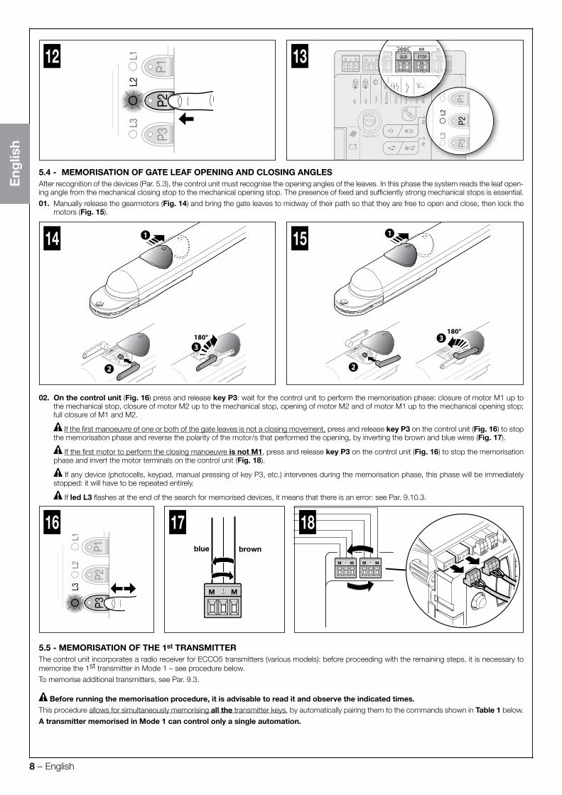
5.4 - MEMORISATION OF GATE LEAF OPENING AND CLOSING ANGLESAfter recognition of the devices (Par. 5.3), the control unit must recognise the opening angles of the leaves. In this phase the system reads the leaf open-ing angle from the mechanical closing stop to the mechanical opening stop. The presence of fixed and sufficiently strong mechanical stops is essential.
01. Manually release the gearmotors (Fig. 14) and bring the gate leaves to midway of their path so that they are free to open and close, then lock themotors (Fig. 15).
180°3
1
2
14
180°3
1
2
15
02. On the control unit (Fig. 16) press and release key P3: wait for the control unit to perform the memorisation phase: closure of motor M1 up tothe mechanical stop, closure of motor M2 up to the mechanical stop, opening of motor M2 and of motor M1 up to the mechanical opening stop;full closure of M1 and M2.
If the first manoeuvre of one or both of the gate leaves is not a closing movement, press and release key P3 on the control unit (Fig. 16) to stop the memorisation phase and reverse the polarity of the motor/s that performed the opening, by inverting the brown and blue wires (Fig. 17).
If the first motor to perform the closing manoeuvre is not M1, press and release key P3 on the control unit (Fig. 16) to stop the memorisation phase and invert the motor terminals on the control unit (Fig. 18).
If any device (photocells, keypad, manual pressing of key P3, etc.) intervenes during the memorisation phase, this phase will be immediately stopped: it will have to be repeated entirely.
If led L3 flashes at the end of the search for memorised devices, it means that there is an error: see Par. 9.10.3.
P1P2
P3
L2L3
L1
16
M M M M
18
M M
17brownblue
5.5 - MEMORISATION OF THE 1st TRANSMITTERThe control unit incorporates a radio receiver for ECCO5 transmitters (various models): before proceeding with the remaining steps, it is necessary to memorise the 1st transmitter in Mode 1 – see procedure below.
To memorise additional transmitters, see Par. 9.3.
Before running the memorisation procedure, it is advisable to read it and observe the indicated times.This procedure allows for simultaneously memorising all the transmitter keys, by automatically pairing them to the commands shown in Table 1 below.
A transmitter memorised in Mode 1 can control only a single automation.

English – 9
Eng
lish
TABLE 1 LED
T5
T2T4T3
T1
P1P2
P3
L2L3
L1
Keys Paired command
T1 Step-by-Step (SbS)
T2 Pedestrian opening
T3 Open only
T4 Close onlyT5 Not used in this application
Memorisation procedure 01. On the control unit (Fig. 19) press and hold key P1 for 3 seconds; when led L1 switches on, release the key.
02. Within 10 seconds from releasing it, press and hold for 3 seconds any button of the transmitter to be memorised.If the memorisation procedure was successful, led P1 (on the control unit) will flash 3 times.
03. To memorise other transmitters, repeat step 02 within the next 10 seconds otherwise the memorisation phase will terminate automatically.
5.6 - BASIC ADJUSTMENTS
5.6.1 - Choosing the gate leaf manoeuvre speedThe opening and closing manoeuvre speed of the gate leaves can be either “slow” or “fast” (the type of selection chosen is visualised by the switching on or off of led L2 on the control unit – Fig. 20):
led L2 off = the “slow” manoeuvre speed was selected.led L2 on = the “fast” manoeuvre speed was selected.
Procedure for selecting the desired speed01. Press and release key P2 several times until led L2 remains lit or switched off (Fig. 20).
5.6.2 - Choosing the operating cycle of the gate leaf manoeuvreThe type of “opening and closing” manoeuvre cycle of the gate leaves can be either “single cycle (semi-automatic)” or “complete cycle (automatic)” (the type of selection chosen is visualised by the switching on or off of led L3 on the control unit – Fig. 21):
led L3 off = the “single cycle (semi-automatic)” manoeuvre cycle was selected (with the first command the gate opens and stays open until the next command that causes it to close).led L3 lit = the “complete cycle (automatic)” manoeuvre cycle was selected (with a single command the gate opens and re-closes automatically after a set “pause time” – to adjust the latter see Par. 9.1.1).
Procedure for selecting the desired cycle01. Press and release key P3 several times until led L3 remains lit or switched off (Fig. 21).
M M M M FLASH BUS STOP SbS
P3P2
P1
L3L2
L1
P1P2
P3
L2L3
L1
20 M M M M FLASH BUS STOP SbS
P3P2
P1
L3L2
L1
P2P1
L3
P3
L2L1
21
single cycle complete cycle
19

10 – English
Eng
lish
6 TESTING AND COMMISSIONING
CAUTION! – The system must be tested by skilled and qualified personnel, who is responsible for defining the tests adopted in rela-tion to the risks present, and for ensuring observance of all legal provisions, standards and regulations, with particular reference to all requirements of the EN 13241-1, EN 12445 and EN 12453 standards which defines the test methods for testing gate automations.
6.1 - TESTING01. Ensure that all the instructions and warnings indicated in Chapter 1 have been strictly observed.02. Using the transmitter, test the gate’s opening and closing movements and ensure that the leaves move as intended. A number of tests should be
performed to ensure that the gate moves smoothly and that there are no assembly defects, incorrect settings, or any points of friction.03. Check the operation of all the system’s safety devices one-by-one (photocells, sensitive edges, etc.) In particular, whenever a device is activated
the ECSbus led (on the control unit) must emit a longer flash to confirm that the control unit has recognised the event.04. To check the photocells and make sure that there is no interference with other devices, pass a cylinder with 5 cm diameter and 30 cm length on
the optical axis, first near the TX then near the RX and, lastly, at the mid-point between the two, and verify that in all these cases the device is trig-gered, switching from the active status to the alarm status and vice-versa; lastly, make sure that it causes the intended action in the control unit;for example: reversal of the movement during the closing manoeuvre.
05. Measure the impact force as specified in the EN 12445 and EN 12453 standards. If the “motor force” control is used as an auxiliary function toreduce the impact force, test and identify the setting that obtains the best results.
6.2 - COMMISSIONINGCommissioning can only be performed after all test phases have been successfully completed. Partial or “makeshift” commissioning is strictly prohibited.01. Draw up the technical file of the automation which should at least include: assembly drawing (for example as in Fig. 3), wiring diagram (for example
Fig. 8), risk analysis and relative solutions adopted, the manufacturer’s declaration of conformity for all the devices used.02. Affix a dataplate on the door, specifying at least the following data: type of automation, name and address of manufacturer (responsible for com-
missioning), serial number, year of construction and CE marking.03. Permanently attach to the gate the label supplied in the pack, regarding the procedure for manual locking/release of the gearmotor.04. Fill in the declaration of conformity and hand it to the owner of the automation (Annex 1).05. Draw up and hand to the owner of the automation the user guide (Chapter 11 – detachable insert).06. Prepare and provide the owner with the “Maintenance schedule” form, containing all maintenance instructions for all devices in the automation.07. Before commissioning the automation, ensure that the owner is properly informed of all risks and hazards still present.
7 MAINTENANCE
Maintenance must be performed in strict observance of the safety provisions in this manual and according to current legislation and standards.The automation’s devices do not require special maintenance; however they should be checked periodically (at least every six months) to ensure com-plete their full efficiency.
To this aim, run all the tests and checks specified under Paragraph 6.1 and consult the maintenance plan of the respective instruction manuals.
8 PRODUCT DISPOSAL
This product is an integral part of the automation and therefore must be disposed together with the latter.As in installation, also at the end of product lifetime, the disassembly and scrapping operations must be performed by qualified personnel.This product is made of various types of materials, some of which can be recycled while others must be scrapped. Seek information on the recycling and disposal systems required by local regulations in your area for this product category.
Caution! – certain parts of the product may contain polluting or hazardous substances that, if released into the environment, may seriously damage the environment and human health.
As indicated by the adjacent symbol, the product may not be disposed of together with domestic waste. Separate the waste into categories for dis-posal, according to the methods set out by legislation in force in your area, or return the product to the retailer when purchasing a new version.
Caution! – local regulations may include the application of heavy fines in the event of improper disposal of this product.
English – 11
Eng
lish
9 FURTHER INFORMATION
9.1 - ADVANCED SETTINGS
9.1.1 - Adjusting the parameters (using the transmitter memorised in Mode 1)The transmitter can be used to set a number of control unit operating parameters:
• Pause time: time during which the gate leaves remain open before re-closing automatically (if the “complete cycle” function is set); see Par. 9.1.1.1
• Pedestrian opening: partial opening mode of the gate leaves, to allow pedestrians to pass through; see Par. 9.1.1.1
• Motor force: maximum force applied by the motor to move the gate leaves; when this value is exceeded, the control unit interprets the occurrenceas an obstacle stopping the gate leaves and, consequently, inverts the direction of movement; see Par. 9.1.1.1
• Step-by-Step (SbS) function: sequence of gate leaf movements associated with each “Step-by-Step” (SbS) command; see Par. 9.1.1.1
• SbS input configuration: adjusts the duration of the motor’s “short reversion” after the closing manoeuvre is executed, in order to reduce the finalresidual force; see Par. 9.1.1.2
• Flash output configuration: adjusts the duration of the motor’s “short reversion” after the opening manoeuvre is executed, in order to reduce thefinal residual force; see Par. 9.1.1.2
• Discharging of Motor 1 and Motor 2 upon closing: adjusts the duration of the motor’s “short reversion” after the closing manoeuvre is executed,in order to reduce the final residual force; see Par. 9.1.1.2
• Discharging of Motor 1 and Motor 2 upon opening: adjusts the duration of the motor’s “short reversion” after the opening manoeuvre is execut-ed, in order to reduce the final residual force; see Par. 9.1.1.2
The adjustment can be effected by means of any transmitter memorised in Mode 1 (as those supplied, see Paragraph 9.3.1). If there is no transmitter memorised in Mode 1, it is possible to memorise one solely for programming purposes then cancelling it (see Paragraph 9.4).
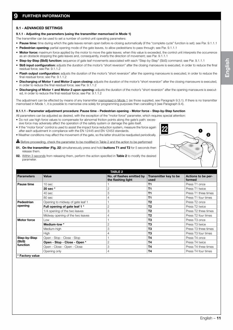
9.1.1.1 - Parameter adjustment procedure: Pause time - Pedestrian opening - Motor force - Step-by-Step function
12
22
All parameters can be adjusted as desired, with the exception of the “motor force” parameter, which requires special attention:• Do not use high force values to compensate for abnormal friction points along the gate’s path: exces-
sive force may adversely affect the operation of the safety system or damage the gate itself.• If the “motor force” control is used to assist the impact force reduction system, measure the force again
after each adjustment in compliance with the EN 12445 and EN 12453 standards.• Weather conditions may affect the movement of the gate, so the latter should be readjusted periodically.
Before proceeding, check the parameter to be modified in Table 2 and the action to be performed:
01. On the transmitter (Fig. 22) simultaneously press and hold buttons T1 and T2 for 5 seconds thenrelease them.
02. Within 3 seconds from releasing them, perform the action specified in Table 2 to modify the desiredparameter.
TABLE 2Parameters Value No. of flashes emitted by
the flashing lightTransmitter key to be used
Actions to be per-formed
Pause time 10 sec 1 T1 Press T1 once20 sec * 2 T1 Press T1 twice40 sec 3 T1 Press T1 three times80 sec 4 T1 Press T1 four times
Pedestrianopening
Opening to midway of gate leaf 1 1 T2 Press T2 onceFull opening of gate leaf 1 * 2 T2 Press T2 twice1/4 opening of the two leaves 3 T2 Press T2 three timesMidway opening of the two leaves 4 T2 Press T2 four times
Motor force Low 1 T3 Press T3 onceMedium-low * 2 T3 Press T3 twiceMedium-high 3 T3 Press T3 three timesHigh 4 T3 Press T3 four times
Step-by-Step (SbS)function
Open - Stop - Close - Stop 1 T4 Press T4 onceOpen - Stop - Close - Open * 2 T4 Press T4 twiceOpen - Close - Open - Close 3 T4 Press T4 three timesOpening only 4 T4 Press T4 four times
* Factory value
12 – English
Eng
lish
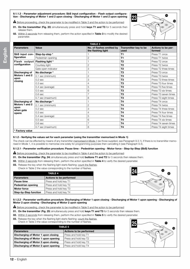
9.1.1.2 - Parameter adjustment procedure: SbS input configuration - Flash output configura-tion - Discharging of Motor 1 and 2 upon closing - Discharging of Motor 1 and 2 upon opening
Before proceeding, check the parameter to be modified in Table 3 and the action to be performed:
01. On the transmitter (Fig. 23) simultaneously press and hold keys T1 and T3 for 5 seconds thenrelease them.
02. Within 3 seconds from releasing them, perform the action specified in Table 3 to modify the desiredparameter.
TABLE 3Parameters Value No. of flashes emitted by
the flashing lightTransmitter key to be used
Actions to be per-formed
SbS input con-figuration
Step-by-step * 1 T1 Press T1 oncePedestrian opening 2 T1 Press T1 twice
Flash output configuration
Flashing light * 1 T2 Press T2 onceCourtesy light 2 T2 Press T2 twiceGate open indicator 3 T2 Press T2 three times
Discharging of Motors 1 and 2 upon closing
No discharge * 1 T3 Press T3 once0.1 sec (minimum) 2 T3 Press T3 twice0.2 sec 3 T3 Press T3 three times0.3 sec 4 T3 Press T3 four times0.4 sec (average) 5 T3 Press T3 five times0.5 sec 6 T3 Press T3 six times0.6 sec 7 T3 Press T3 seven times0.7 sec (maximum) 8 T3 Press T3 eight times
Discharging of Motors 1 and 2 uponwhen gate opens
No discharge * 1 T4 Press T4 once0.1 sec (minimum) 2 T4 Press T4 twice0.2 sec 3 T4 Press T4 three times0.3 sec 4 T4 Press T4 four times0.4 sec (average) 5 T4 Press T4 five times0.5 sec 6 T4 Press T4 six times0.6 sec 7 T4 Press T4 seven times0.7 sec (maximum) 8 T4 Press T4 eight times
* Factory value
9.1.2 - Verifying the values set for each parameter (using the transmitter memorised in Mode 1)The check can be effected by means of any transmitter memorised in Mode 1 (as those supplied, see Paragraph 9.3.1). If there is no transmitter memo-rised in Mode 1, it is possible to memorise one solely for programming purposes then cancelling it (see Paragraph 9.4).
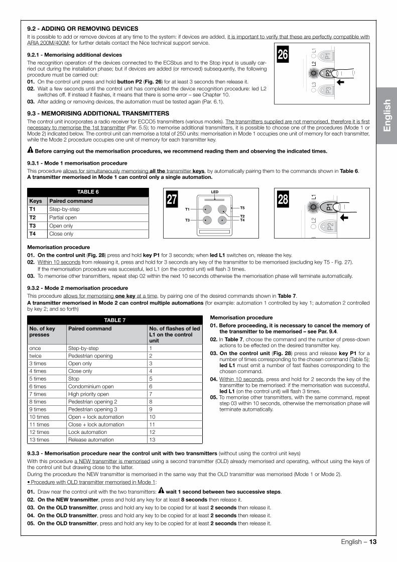
9.1.2.1 - Parameter verification procedure: Pause time - Pedestrian opening - Motor force - Step-by-Step (SbS) function
Before proceeding, check the parameter to be modified in Table 4 and the action to be performed: 01. On the transmitter (Fig. 24) simultaneously press and hold buttons T1 and T2 for 5 seconds then release them.
02. Within 3 seconds from releasing them, perform the action specified in Table 4 to verify the desired parameter.
03. Release the key when the flashing light starts flashing: count the flashes.Check in Table 2 the value corresponding to the number of flashes.
TABLE 4
Parameters Actions to be performedPause time Press and hold key T1Pedestrian opening Press and hold key T2Motor force Press and hold key T3Step-by-Step function Press and hold key T4
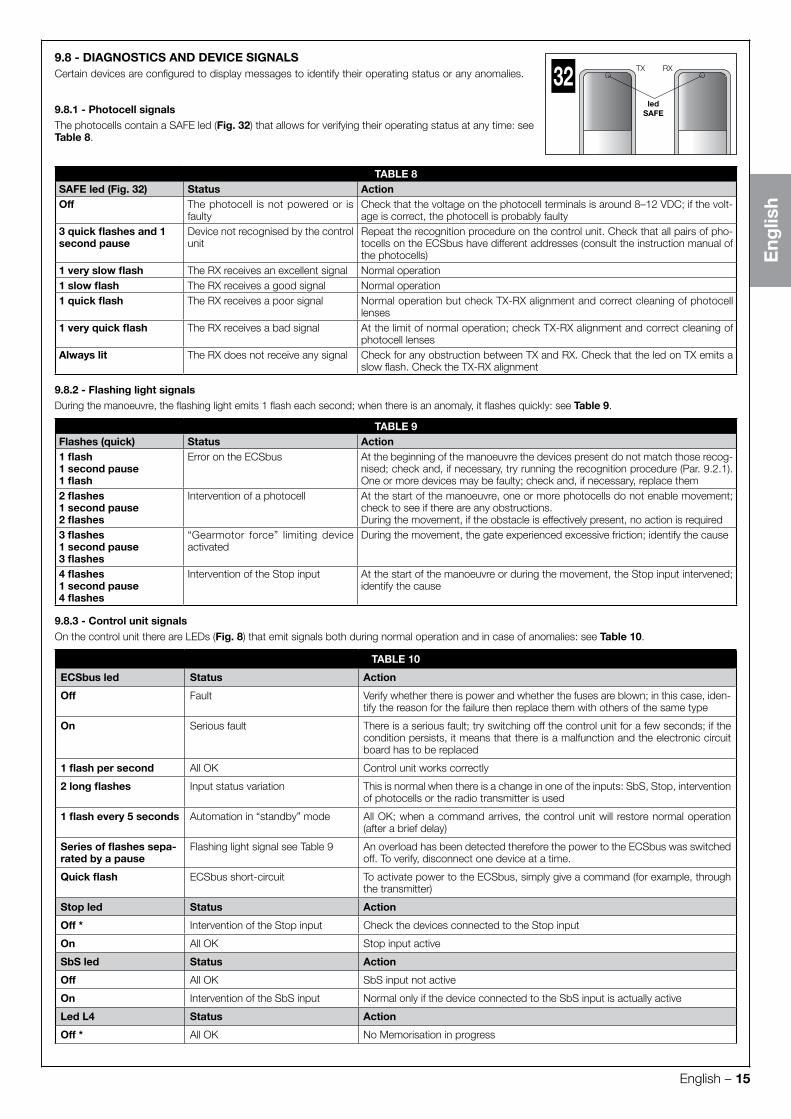
9.1.2.2 - Parameter verification procedure: Discharging of Motor 1 upon closing - Discharging of Motor 1 upon opening - Discharging of Motor 2 upon closing - Discharging of Motor 2 upon opening
Before proceeding, check the parameter to be modified in Table 5 and the action to be performed: 01. On the transmitter (Fig. 25) simultaneously press and hold keys T1 and T3 for 5 seconds then release them.
02. Within 3 seconds from releasing them, perform the action specified in Table 5 to verify the desired parameter.
03. Release the key when the flashing light starts flashing: count the flashes.Check in Table 3 the value corresponding to the number of flashes.
TABLE 5
Parameters Actions to be performedDischarging of Motor 1 upon closing Press and hold key T1Discharging of Motor 1 upon opening Press and hold key T2Discharging of Motor 2 upon closing Press and hold key T3Discharging of Motor 2 upon opening Press and hold key T4
T1
T323
1224
T1
T3
25
English – 13
Eng
lish
9.2 - ADDING OR REMOVING DEVICESIt is possible to add or remove devices at any time to the system: if devices are added, it is important to verify that these are perfectly compatible with ARIA 200M/400M; for further details contact the Nice technical support service.
9.2.1 - Memorising additional devicesThe recognition operation of the devices connected to the ECSbus and to the Stop input is usually car-ried out during the installation phase; but if devices are added (or removed) subsequently, the following procedure must be carried out:01. On the control unit press and hold button P2 (Fig. 26) for at least 3 seconds then release it.02. Wait a few seconds until the control unit has completed the device recognition procedure: led L2
switches off. If instead it flashes, it means that there is some error – see Chapter 10.03. After adding or removing devices, the automation must be tested again (Par. 6.1).
9.3 - MEMORISING ADDITIONAL TRANSMITTERSThe control unit incorporates a radio receiver for ECCO5 transmitters (various models). The transmitters supplied are not memorised, therefore it is first necessary to memorise the 1st transmitter (Par. 5.5); to memorise additional transmitters, it is possible to choose one of the procedures (Mode 1 or Mode 2) indicated below. The control unit can memorise a total of 250 units: memorisation in Mode 1 occupies one unit of memory for each transmitter, while the Mode 2 procedure occupies one unit of memory for each transmitter key.
Before carrying out the memorisation procedures, we recommend reading them and observing the indicated times.
9.3.1 - Mode 1 memorisation procedure This procedure allows for simultaneously memorising all the transmitter keys, by automatically pairing them to the commands shown in Table 6.A transmitter memorised in Mode 1 can control only a single automation.
LED
T5
T2T4T3
T1
27
P1P2
P3
L2L3
L128TABLE 6
Keys Paired command
T1 Step-by-step
T2 Partial open
T3 Open only
T4 Close only
Memorisation procedure 01. On the control unit (Fig. 28) press and hold key P1 for 3 seconds; when led L1 switches on, release the key.02. Within 10 seconds from releasing it, press and hold for 3 seconds any key of the transmitter to be memorised (excluding key T5 - Fig. 27).
If the memorisation procedure was successful, led L1 (on the control unit) will flash 3 times.03. To memorise other transmitters, repeat step 02 within the next 10 seconds otherwise the memorisation phase will terminate automatically.
9.3.2 - Mode 2 memorisation procedureThis procedure allows for memorising one key at a time, by pairing one of the desired commands shown in Table 7.A transmitter memorised in Mode 2 can control multiple automations (for example: automation 1 controlled by key 1; automation 2 controlled by key 2; and so forth)
TABLE 7 Memorisation procedure 01. Before proceeding, it is necessary to cancel the memory of
the transmitter to be memorised – see Par. 9.4.
02. In Table 7, choose the command and the number of press-downactions to be effected on the desired transmitter key.
03. On the control unit (Fig. 28) press and release key P1 for anumber of times corresponding to the chosen command (Table 5); led L1 must emit a number of fast flashes corresponding to thechosen command.
04. Within 10 seconds, press and hold for 2 seconds the key of thetransmitter to be memorised: if the memorisation was successful,led L1 (on the control unit) will flash 3 times.
05. To memorise other transmitters, with the same command, repeatstep 03 within 10 seconds, otherwise the memorisation phase willterminate automatically.
No. of key presses
Paired command No. of flashes of led L1 on the control unit
once Step-by-step 1twice Pedestrian opening 23 times Open only 34 times Close only 45 times Stop 56 times Condominium open 67 times High priority open 78 times Pedestrian opening 2 89 times Pedestrian opening 3 910 times Open + lock automation 1011 times Close + lock automation 1112 times Lock automation 1213 times Release automation 13
9.3.3 - Memorisation procedure near the control unit with two transmitters (without using the control unit keys)
With this procedure a NEW transmitter is memorised using a second transmitter (OLD) already memorised and operating, without using the keys of the control unit but drawing close to the latter.During the procedure the NEW transmitter is memorised in the same way that the OLD transmitter was memorised (Mode 1 or Mode 2).
• Procedure with OLD transmitter memorised in Mode 1:
01. Draw near the control unit with the two transmitters: wait 1 second between two successive steps.
02. On the NEW transmitter, press and hold any key for at least 8 seconds then release it.
03. On the OLD transmitter, press and hold any key to be copied for at least 2 seconds then release it.
04. On the OLD transmitter, press and hold any key to be copied for at least 2 seconds then release it.
05. On the OLD transmitter, press and hold any key to be copied for at least 2 seconds then release it.
P1P2
P3
L2L3
L126

14 – English
Eng
lish
06. On the NEW transmitter, press and hold any key to be memorised for at least 5 seconds then release it.
Repeat the procedure for each transmitter to be memorised.
• Procedure with OLD transmitter memorised in Mode 2:
01. Draw near the control unit with the two transmitters: wait 1 second between two successive steps.
02. On the NEW transmitter, press and hold the key to be memorised for at least 8 seconds then release it.
03. On the OLD transmitter, press and hold the key to be copied for at least 2 seconds then release it.
04. On the OLD transmitter, press and hold the key to be copied for at least 2 seconds then release it.
05. On the OLD transmitter, press and hold the key to be copied for at least 2 seconds then release it.
06. On the NEW transmitter, press and hold the key to be memorised for at least 5 seconds then release it.
Repeat the procedure for each transmitter to be memorised.
9.4 - DELETING THE MEMORY OF THE INDIVIDUAL TRANSMITTER FROM THE CONTROL UNIT’S MEMORYThis procedure allows for cancelling a single transmitter (memorised in Mode 1) or only one of its keys (memorised in Mode 2): it is neces-sary to arrange the transmitter to be cancelled and simultaneously be able to access the control unit (before proceeding, open the gearmo-tor – Fig. 9).
P1P2
P3
L2L3
L129• Procedure with transmitter memorised in Mode 1:
01. On the control unit (Fig. 29) press and hold key P1 until the end of the procedure.
02. When led L1 lights up, while keeping key P1 pressed, also press and hold any key of the transmitter to be cancelled, until led L1 flashes 5 times, then release both keys.
Repeat the procedure for each transmitter to be cancelled.
• Procedure with transmitter memorised in Mode 2:
01. On the control unit (Fig. 29) press and hold key P1 until the end of the procedure.
02. When led L1 lights up, while keeping key P1 pressed, also press and hold the key of the transmitter to be cancelled, until led L1 flashes 5 times,then release both keys
Repeat the procedure for each transmitter to be cancelled.
9.5 - COMPLETE DELETION OF THE RADIO MEMORYThis procedure allows for cancelling ALL memorised transmitters: the procedure must be carried out on the control unit (before proceeding, open the cover of the gearmotor – Fig. 9).
01. On the control unit (Fig. 29) press and hold key P1.
02. Check that led L1 lights up for 4/5 seconds, that it switches off then flashes 3 times.
03. Release key P1 precisely at the 3rd flash.
04. Check that led L1 emits very fast flashes.
05. Check that led L1 emits 5 slow flashes = deletion completed.
9.6 - INSTALLING THE BACK-UP BATTERY (model PR100)
CAUTION! - The electrical connection of the back-up battery to the control unit must be made exclusively after completing all the installation and programming stages, as the battery is an emergency power supply.To install the back-up battery and connect it to the control unit, see Fig. 30 and consult the respective instruction manual.
When the automation is powered by the back-up battery, 60 seconds after a manoeuvre is completed the control unit automatically switches off the ECSbus output (and all devices connected to it), the Flash output and all LEDs (with the exception of the ECSbus led, which flashes more slowly): this automatic switching off is the “Standby” function.Subsequently, when the control unit receives a command, the normal operating mode is restored with a short delay; this function is used to reduce consumption (very important when the automation is powered by a battery)
9.7 - INSTALLING THE SOLAR POWER SYSTEM KIT model SOLEKIT
CAUTION! - When the automation mechanism is powered exclusively by the solar power supply system, IT MUST NOT BE POWERED by the electricity grid at the same time.To connect the SOLEKIT solar power supply system to the control unit, see Fig. 31 and consult the relevant instruction manual.
1
2
PR100
1
2
SOLEKIT3130
English – 15
Eng
lish
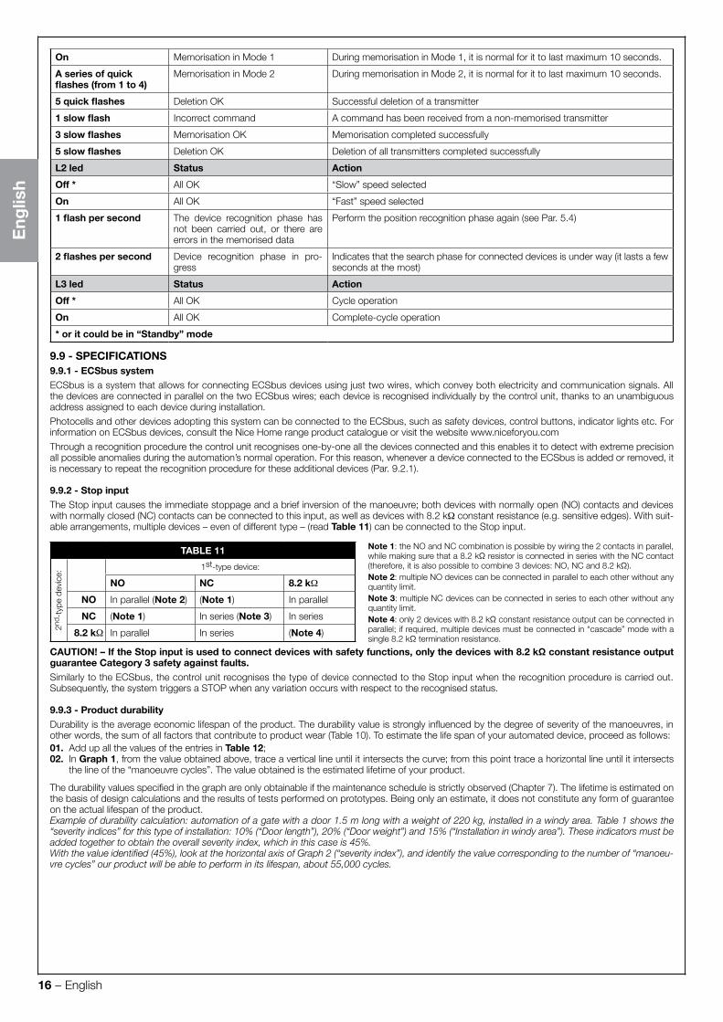
9.8 - DIAGNOSTICS AND DEVICE SIGNALSCertain devices are configured to display messages to identify their operating status or any anomalies.
9.8.1 - Photocell signalsThe photocells contain a SAFE led (Fig. 32) that allows for verifying their operating status at any time: see Table 8.
TABLE 8SAFE led (Fig. 32) Status ActionOff The photocell is not powered or is
faultyCheck that the voltage on the photocell terminals is around 8–12 VDC; if the volt-age is correct, the photocell is probably faulty
3 quick flashes and 1 second pause
Device not recognised by the control unit
Repeat the recognition procedure on the control unit. Check that all pairs of pho-tocells on the ECSbus have different addresses (consult the instruction manual of the photocells)
1 very slow flash The RX receives an excellent signal Normal operation1 slow flash The RX receives a good signal Normal operation1 quick flash The RX receives a poor signal Normal operation but check TX-RX alignment and correct cleaning of photocell
lenses1 very quick flash The RX receives a bad signal At the limit of normal operation; check TX-RX alignment and correct cleaning of
photocell lensesAlways lit The RX does not receive any signal Check for any obstruction between TX and RX. Check that the led on TX emits a
slow flash. Check the TX-RX alignment
9.8.2 - Flashing light signalsDuring the manoeuvre, the flashing light emits 1 flash each second; when there is an anomaly, it flashes quickly: see Table 9.
TABLE 9Flashes (quick) Status Action1 flash1 second pause1 flash
Error on the ECSbus At the beginning of the manoeuvre the devices present do not match those recog-nised; check and, if necessary, try running the recognition procedure (Par. 9.2.1). One or more devices may be faulty; check and, if necessary, replace them
2 flashes1 second pause2 flashes
Intervention of a photocell At the start of the manoeuvre, one or more photocells do not enable movement; check to see if there are any obstructions.During the movement, if the obstacle is effectively present, no action is required
3 flashes1 second pause3 flashes
“Gearmotor force” limiting device activated
During the movement, the gate experienced excessive friction; identify the cause
4 flashes1 second pause4 flashes
Intervention of the Stop input At the start of the manoeuvre or during the movement, the Stop input intervened; identify the cause
9.8.3 - Control unit signalsOn the control unit there are LEDs (Fig. 8) that emit signals both during normal operation and in case of anomalies: see Table 10.
TABLE 10
ECSbus led Status Action
Off Fault Verify whether there is power and whether the fuses are blown; in this case, iden-tify the reason for the failure then replace them with others of the same type
On Serious fault There is a serious fault; try switching off the control unit for a few seconds; if the condition persists, it means that there is a malfunction and the electronic circuit board has to be replaced
1 flash per second All OK Control unit works correctly
2 long flashes Input status variation This is normal when there is a change in one of the inputs: SbS, Stop, intervention of photocells or the radio transmitter is used
1 flash every 5 seconds Automation in “standby” mode All OK; when a command arrives, the control unit will restore normal operation (after a brief delay)
Series of flashes sepa-rated by a pause
Flashing light signal see Table 9 An overload has been detected therefore the power to the ECSbus was switched off. To verify, disconnect one device at a time.
Quick flash ECSbus short-circuit To activate power to the ECSbus, simply give a command (for example, through the transmitter)
Stop led Status Action
Off * Intervention of the Stop input Check the devices connected to the Stop input
On All OK Stop input active
SbS led Status Action
Off All OK SbS input not active
On Intervention of the SbS input Normal only if the device connected to the SbS input is actually active
Led L4 Status Action
Off * All OK No Memorisation in progress
ledSAFE
TX RX32
16 – English
Eng
lish
On Memorisation in Mode 1 During memorisation in Mode 1, it is normal for it to last maximum 10 seconds.
A series of quick flashes (from 1 to 4)
Memorisation in Mode 2 During memorisation in Mode 2, it is normal for it to last maximum 10 seconds.
5 quick flashes Deletion OK Successful deletion of a transmitter
1 slow flash Incorrect command A command has been received from a non-memorised transmitter
3 slow flashes Memorisation OK Memorisation completed successfully
5 slow flashes Deletion OK Deletion of all transmitters completed successfully
L2 led Status Action
Off * All OK “Slow” speed selected
On All OK “Fast” speed selected
1 flash per second The device recognition phase has not been carried out, or there are errors in the memorised data
Perform the position recognition phase again (see Par. 5.4)
2 flashes per second Device recognition phase in pro-gress
Indicates that the search phase for connected devices is under way (it lasts a few seconds at the most)
L3 led Status Action
Off * All OK Cycle operation
On All OK Complete-cycle operation
* or it could be in “Standby” mode
9.9 - SPECIFICATIONS9.9.1 - ECSbus systemECSbus is a system that allows for connecting ECSbus devices using just two wires, which convey both electricity and communication signals. All the devices are connected in parallel on the two ECSbus wires; each device is recognised individually by the control unit, thanks to an unambiguous address assigned to each device during installation.
Photocells and other devices adopting this system can be connected to the ECSbus, such as safety devices, control buttons, indicator lights etc. For information on ECSbus devices, consult the Nice Home range product catalogue or visit the website www.niceforyou.com
Through a recognition procedure the control unit recognises one-by-one all the devices connected and this enables it to detect with extreme precision all possible anomalies during the automation’s normal operation. For this reason, whenever a device connected to the ECSbus is added or removed, it is necessary to repeat the recognition procedure for these additional devices (Par. 9.2.1).
9.9.2 - Stop inputThe Stop input causes the immediate stoppage and a brief inversion of the manoeuvre; both devices with normally open (NO) contacts and devices with normally closed (NC) contacts can be connected to this input, as well as devices with 8.2 kΩ constant resistance (e.g. sensitive edges). With suit-able arrangements, multiple devices – even of different type – (read Table 11) can be connected to the Stop input.
TABLE 11 Note 1: the NO and NC combination is possible by wiring the 2 contacts in parallel, while making sure that a 8.2 kΩ resistor is connected in series with the NC contact (therefore, it is also possible to combine 3 devices: NO, NC and 8.2 kΩ).Note 2: multiple NO devices can be connected in parallel to each other without any quantity limit.Note 3: multiple NC devices can be connected in series to each other without any quantity limit.Note 4: only 2 devices with 8.2 kΩ constant resistance output can be connected in parallel; if required, multiple devices must be connected in “cascade” mode with a single 8.2 kΩ termination resistance.
2nd -
type
dev
ice:
1st-type device:
NO NC 8.2 kΩ
NO In parallel (Note 2) (Note 1) In parallel
NC (Note 1) In series (Note 3) In series
8.2 kΩ In parallel In series (Note 4)
CAUTION! – If the Stop input is used to connect devices with safety functions, only the devices with 8.2 kΩ constant resistance output guarantee Category 3 safety against faults.Similarly to the ECSbus, the control unit recognises the type of device connected to the Stop input when the recognition procedure is carried out. Subsequently, the system triggers a STOP when any variation occurs with respect to the recognised status.
9.9.3 - Product durabilityDurability is the average economic lifespan of the product. The durability value is strongly influenced by the degree of severity of the manoeuvres, in other words, the sum of all factors that contribute to product wear (Table 10). To estimate the life span of your automated device, proceed as follows:01. Add up all the values of the entries in Table 12;02. In Graph 1, from the value obtained above, trace a vertical line until it intersects the curve; from this point trace a horizontal line until it intersects
the line of the “manoeuvre cycles”. The value obtained is the estimated lifetime of your product.
The durability values specified in the graph are only obtainable if the maintenance schedule is strictly observed (Chapter 7). The lifetime is estimated on the basis of design calculations and the results of tests performed on prototypes. Being only an estimate, it does not constitute any form of guarantee on the actual lifespan of the product.Example of durability calculation: automation of a gate with a door 1.5 m long with a weight of 220 kg, installed in a windy area. Table 1 shows the “severity indices” for this type of installation: 10% (“Door length”), 20% (“Door weight”) and 15% (“Installation in windy area”). These indicators must be added together to obtain the overall severity index, which in this case is 45%.With the value identified (45%), look at the horizontal axis of Graph 2 (“severity index”), and identify the value corresponding to the number of “manoeu-vre cycles” our product will be able to perform in its lifespan, about 55,000 cycles.

English – 17
Eng
lish
TABLE 12Severity index
ARIA200M ARIA400M> 100 kg 10% 10%> 200 kg 20% 20%Weight of the leaf> 300 kg - 30%> 400 kg - 40%1 – 1.5 m 10% -
1.5 – 2.5 m 20% -Length of the leaf2.5 – 3.5 - 20%3.5 – 4.5 - 30%
Ambient temperature greater than 40°C or lower than 0°C, or humidity greater than 80% 20% 20%
Solid leaf 15% 15%Installation in suction cup area 15% 15%
GRAPH 1
25.000
50.000
75.000
100.000
125.000
Severity index (%)
man
oeu
vre
cycl
es
10 TROUBLESHOOTING
Table 15 contains useful information to help solve any malfunctions that may occur during installation or in case of a fault.
TABLE 15
Symptoms Probable cause and possible solution
The radio transmitter does not emit any signal and the corresponding led fails to light up
Check the batteries: if they are flat, replace them (consult the transmitter’s instruction manual).
The manoeuvre fails to start and the ECSbus led on the control unit does not flash
• Check that the power cable is correctly inserted in thepower outlet.• Check the fuses; if they have tripped, determine thecause of the fault and replace them with others of thesame type: see Fig. 33.
33
The manoeuvre fails to start and the automation’s flashing light is off
Check that the command is actually received. If the command reaches the SbS input, the relevant SbS led lights up; if a transmitter is used, the ECSbus led must emit 2 long flashes.
The manoeuvre fails to start and the automation’s flashing light emits a few flashes
• Check that the Stop input is active (in other words, that the Stop led is lit). Should this not be the case,check the device connected to the Stop input.• The photocells test (which the control unit performs at the start of each manoeuvre) failed: check thephotocells, by verifying their status in Table 8.
The manoeuvre starts but is immedi-ately followed by a reverse run com-manded by the control unit
The programmed “motor force” setting is too low to move the gate. Check whether there are any obsta-cles obstructing the gate’s movement and, if necessary, select a higher force as described in Par. 9.1.1.
The manoeuvre is carried out but the flashing light is not working
During the manoeuvre, check that the Flash terminal of the flashing light is powered (being intermittent, the voltage value is irrelevant: roughly 10–30 V ); if it is powered, the problem is due to the lamp not working (consult the flashing light’s instruction manual to replace it).

A
11 USER MANUAL (for the homeowner). This page can be downloaded from the easygate.com.au website.
This user guide should be handed to all user’s of the automation. 11.1 – WARNINGS.
• Monitor the gate while it is moving and keep at a safe distance until it is fully open or closed; do not transit through it until the gate isfully open and stopped.• Do not let children play near the gate or with its commands.• Keep the transmitters away from children.• Suspend the use of the automation immediately as soon as you notice something abnormal in the operation (noises or jolting move-ments); failure to follow this warning may cause serious danger and accidents.• Do not touch moving parts.• Regular maintenance checks must be carried out by qualified personnel according to the maintenance plan.• Maintenance or repairs must only be carried out by qualified technical personnel.• Send a command with the safety devices disabled:If the safety devices do not work properly or are out of order, the gate can still be operated.
01. Activate the gate control with the transmitter or the devices connected to the SbS terminal. If the safety devices give the enable signal, the gateopens normally; otherwise, reattempt within 3 seconds and keep the control activated.
02. After approximately 2 seconds the gate will start moving in the “man present” mode, that is, so long as the control is kept activated the gate willkeep moving; as soon as the control is released the gate will stop.
If the safety devices are out of order, arrange to repair the automation as soon as possible.
11.2 – Manually releasing and locking the gearmotorARIA gearmotors (models 200M/400M) are equipped with a mechanical system that allows for opening and closing the gate manually. Manual operation must be performed in the case of a power outage or in the event of anomalies affecting the system. In case of a power outage, a back-up battery can be used (model PR100 - not supplied) (see Chapter 9 - Further information, or the relevant instruction manual).In the event of a gearmotor fault, it is still possible to try release the motor to check whether the fault lies in the release mechanism.
180°3
1
2
180°3
1
2
11.3 – User-admissible maintenance operationsThe operations that the user must carry out periodically are listed below:01. Disconnect the power supply.02. Check for any deterioration in automation system components, paying special attention to erosion or oxidation of the structural parts. Replace any
parts which are below the required standard.03. Check that all screw fasteners are properly tightened.04. Check that the nut and worm screw are adequately greased.05. Check the state of wear of all moving parts and replace any worn components.06. Connect the power supplies up again, and run all the tests and checks described in Chapter 5.07. Cleaning of surfaces: use a slightly damp (not wet) cloth. Do not use substances containing alcohol, benzene, thinners or other flammable sub-
stances; the use of these substances may damage the devices and cause fires or electric shocks.
For all other equipment in the system, refer to the respective user manuals.
11.4 – Replacing the transmitter batteryIf, when a key is pressed, the relevant led turns on then immediately fades and turns off, it means that the battery is completely flat and should be immediately replaced.If instead the led turns on only for a moment, it means that the battery is partially flat; the key must be kept pressed for at least half a second for the transmitter to attempt to send the command.
Batteries contain polluting substances: do not dispose of them together with common waste but adopt the methods envisaged by the local regulations.
a b c d

IS04
69A
00M
M_3
0-12
-201
6