AREVA NP Inc. - ART Program 2010/Pebble Bed Reactor Plant Design Description - AREVA.pdfAREVA NP...
309
20004-018 (10/18/2010) PROPRIETARY Page 1 of 309 AREVA NP Inc. Technical Data Record Document No.: 12 - 9149697 - 000 Pebble Bed Reactor Plant Design Description Disclaimer This report was prepared as an account of work sponsored by an agency of the United States Government. Neither the United States Government nor any agency thereof, nor any of their employees, nor their contractors and subcontractors, makes any warranty, express or implied, or assumes any legal liability or responsibility for the accuracy, completeness, or usefulness of any information, apparatus, product, or process disclosed, or represents that its use would not infringe privately owned rights. Reference herein to any specific commercial product, process, or service by trade name, trademark, manufacturer, or otherwise does not necessarily constitute or imply its endorsement, recommendation, or favoring by the United States Government or any agency thereof. The views and opinions of authors expressed herein do not necessarily state or reflect those of the United States Government or any agency thereof. BEA Contract No. 000 75310
Transcript of AREVA NP Inc. - ART Program 2010/Pebble Bed Reactor Plant Design Description - AREVA.pdfAREVA NP...

20004-018 (10/18/2010)
PROPRIETARY
Page 1 of 309
AREVA NP Inc.
Technical Data Record
Document No.: 12 - 9149697 - 000
Pebble Bed Reactor Plant Design Description
Disclaimer This report was prepared as an account of work sponsored by an agency of the United States Government. Neither the United States Government nor any agency thereof, nor any of their employees, nor their contractors and subcontractors, makes any warranty, express or implied, or assumes any legal liability or responsibility for the accuracy, completeness, or usefulness of any information, apparatus, product, or process disclosed, or represents that its use would not infringe privately owned rights. Reference herein to any specific commercial product, process, or service by trade name, trademark, manufacturer, or otherwise does not necessarily constitute or imply its endorsement, recommendation, or favoring by the United States Government or any agency thereof. The views and opinions of authors expressed herein do not necessarily state or reflect those of the United States Government or any agency thereof.
BEA Contract No. 000 75310

AREVA
Pebble Bed Reactor Plant Design Description
20004-018 (10/18/2010)
Document No.: 12-9149697-000
Safety Related? DYES l:8J NO
Does this document contain assumptions requiring verification? DYES l:8J NO
Does this document contain Customer Required Format? DYES l:8J NO
Signature Block
P/LP, RlLR, Pages/SectionsName and A/A-CRF, Prepared/Reviewed/
TitlelDiscipline Signature A/A-CRI Date Approved or Comments
Nathan Hottle / Systems fkJt 1f/;.YKLP
J!JJ/ldIJALL
Engineer, Nuclear Island
Dominique Hittner / R&D p(lt LR .1!U/i[)(! ALLManager, Product and 1/)1/,"Technology Division
Lewis Lommers I HTR A
1/";-1'11ALL
Project Engineering ~'l' ---Manager
Farshid Shahrokhi I HTR
~~A 13\ (G~\\
ALLTechnical Integration
Note: P/LP designates Preparer (P), Lead Preparer (LP)RlLR designates Reviewer (R), Lead Reviewer (LR)AlA-CRF designates Approver (A), Approver of Customer Requested Format (A-CRF)AlA-CRI designates Approver (A), Approver - Confirming Reviewer Independence (A-CRI)
Page 2

20004-018 (10/18/2010)
Document No.: 12-9149697-000
Pebble Bed Reactor Plant Design Description
Page 3
PROPRIETARY
Record of Revision Revision
No. Pages/Sections/
Paragraphs Changed Brief Description / Change Authorization 000 -- Initial Issue
Document No.: 12-9149697-000
Pebble Bed Reactor Plant Design Description
Page 4
PROPRIETARY
List of Contributors
AREVA NP Inc. Randy Abernethy Rick Campanella Mark Elsishans
James Geschwindt Mike Gould
Dan Grundman Paul Kendall
Lewis Lommers James Sawabe Caleb Tomlin Kevin Wong
AREVA GmbH
Dr. Gerd Brinkmann Dipl. Ing. Dieter Vanvor
AREVA SAS
Sophie Larmignat Sylvain Menou
The Shaw Group Inc.
Jeff Ashworth Jaime Basto Hope Chase
William Killilea Reiner Kuhr
William Martin Lane McDonough
Tom St. Louis Peter Wells
NovaTech
Anne Austin
FZJ Jülich Prof. Dr. Heiko Barnert
Dr. Heinz Nabielek Dr. H. F. Nießen
Dr. Ing. Kay Nünighoff Dipl. Ing. Peter Pohl
Dr. H. J. Rütten Dr. Bärbel Schlögl
Dr. Karl Verfondern Dr. Christoph Pohl

Document No.: 12-9149697-000
Pebble Bed Reactor Plant Design Description
Page 5
PROPRIETARY
Table of Contents Page
SIGNATURE BLOCK................................................................................................................................2
RECORD OF REVISION ..........................................................................................................................3
LIST OF CONTRIBUTORS.......................................................................................................................4
LIST OF TABLES ...................................................................................................................................10
LIST OF FIGURES .................................................................................................................................12
ACRONYMS AND DEFINITIONS...........................................................................................................15
1.0 SUMMARY..................................................................................................................................16 1.1 Purpose...........................................................................................................................16 1.2 PBR Background.............................................................................................................16
1.2.1 Early Developments.......................................................................................16 1.2.2 HTR-Module 200............................................................................................16 1.2.3 Recent Developments....................................................................................17
2.0 INTRODUCTION.........................................................................................................................18 2.1 NGNP Project..................................................................................................................18
2.1.1 NGNP Project Objectives...............................................................................18 2.2 PBR Technology Status Assessment..............................................................................19 2.3 Approach to Plant Design Description.............................................................................21 2.4 Document Structure ........................................................................................................21
3.0 REFERENCE DESIGN – HTR-MODULE ...................................................................................22 3.1 Plant Overview ................................................................................................................22
3.1.1 Plant Description............................................................................................22 3.1.2 Characteristic Safety Features.......................................................................22
3.2 Reactor............................................................................................................................26 3.2.1 Fuel Elements ................................................................................................27 3.2.2 Reactor Core..................................................................................................29 3.2.3 Core Internals ................................................................................................32 3.2.4 Control and Shutdown Systems.....................................................................38 3.2.5 Core Instrumentation .....................................................................................42
3.3 Primary Circuit Components ...........................................................................................65 3.3.1 Primary Circuit Description ............................................................................65
Document No.: 12-9149697-000
Pebble Bed Reactor Plant Design Description
Table of Contents (continued) Page
Page 6
PROPRIETARY
3.3.2 Reactor Pressure Vessel (RPV) ....................................................................68 3.3.3 Gas Duct Pressure Vessel and Hot Gas Duct ...............................................70 3.3.4 Steam Generator Pressure Vessel and Internals...........................................72 3.3.5 Vessel Supports.............................................................................................77 3.3.6 Main Circulator...............................................................................................78 3.3.7 Pressure Control and Relief...........................................................................81 3.3.8 Primary System Isolation ...............................................................................83 3.3.9 Inservice Inspection of the Pressure Vessel Unit...........................................84
3.4 Residual Heat Removal.................................................................................................105 3.4.1 Residual Heat Removal by the Main Heat Transfer System........................105 3.4.2 Residual Heat Removal by the Cavity Cooler ..............................................105 3.4.3 Cooling of RPV and Steam Generator Supports .........................................107
3.5 Helium Purification and Supporting Systems ................................................................107 3.5.1 Helium Purification System ..........................................................................107 3.5.2 Helium Supply and Storage System ............................................................111 3.5.3 Dump System (for Helium Supporting Systems and Fuel Handling
Equipment) ..................................................................................................112 3.5.4 Gas Evacuation System (for Primary System).............................................112 3.5.5 Gaseous Waste Storage System.................................................................113
3.6 Fuel Handling and Storage System...............................................................................120 3.6.1 Fuel Handling System..................................................................................120 3.6.2 New Fuel Storage ........................................................................................126 3.6.3 Spent Fuel Storage ......................................................................................127 3.6.4 Handling of Components for Maintenance and Repair of Fuel Feed and
Discharge Equipment ..................................................................................129 3.7 Reactor Auxiliary Systems ............................................................................................136
3.7.1 Component Handling Equipment .................................................................136 3.7.2 Sampling System (Gas Analysis System)....................................................137 3.7.3 Core Barrel Leak Testing System ................................................................138 3.7.4 Radioactive Waste Processing Systems......................................................139 3.7.5 Nuclear Buildings Drainage System ............................................................143
3.8 Energy Conversion Plant...............................................................................................147

Document No.: 12-9149697-000
Pebble Bed Reactor Plant Design Description
Table of Contents (continued) Page
Page 7
PROPRIETARY
3.8.1 Water/Steam Cycle ......................................................................................147 3.8.2 Turbine Generator........................................................................................150 3.8.3 Other Energy Conversion Plant Systems ....................................................152
3.9 Cooling Water Systems.................................................................................................156 3.9.1 General Systems Configuration ...................................................................156 3.9.2 Circulating Water System with Wet/Dry Cooling Tower ...............................157 3.9.3 Closed Cooling Water Systems ...................................................................158 3.9.4 Service Water Systems................................................................................163
3.10 HVAC Systems..............................................................................................................169 3.10.1 Nuclear HVAC Systems for the Controlled Area..........................................169 3.10.2 HVAC Systems in the Switchgear and Emergency Supply Building............175 3.10.3 Ventilation of Remote Shutdown Station in the Reactor Building ................178 3.10.4 Other HVAC Systems ..................................................................................180
3.11 Plant Electrical Distribution System...............................................................................180 3.11.1 Auxiliary Power Supply ................................................................................180 3.11.2 Emergency Power System...........................................................................181 3.11.3 Grounding and Lightning Protection ............................................................182 3.11.4 Communication Systems .............................................................................182 3.11.5 Alarm System...............................................................................................182 3.11.6 Lighting and Service Power System ............................................................183
3.12 Plant Instrumentation and Control Systems ..................................................................185 3.12.1 Reactor Protection System ..........................................................................185 3.12.2 Operational Instrumentation and Control System ........................................186 3.12.3 Accident Monitoring System ........................................................................186 3.12.4 Main Control Room ......................................................................................187 3.12.5 Remote Shutdown Station ...........................................................................187
3.13 Power Plant Auxiliary Systems......................................................................................188 3.13.1 Cranes and Elevators ..................................................................................188 3.13.2 Compressed Air System ..............................................................................189 3.13.3 Demineralized Water Supply System ..........................................................189 3.13.4 Auxiliary Steam System ...............................................................................190

Document No.: 12-9149697-000
Pebble Bed Reactor Plant Design Description
Table of Contents (continued) Page
Page 8
PROPRIETARY
3.13.5 Space Heating System ................................................................................190 3.13.6 Chilled Water System ..................................................................................190 3.13.7 Fire Protection Equipment ...........................................................................190 3.13.8 Other Balance of Plant Auxiliary Systems ...................................................194
3.14 Plant Structures.............................................................................................................194 3.14.1 Overall Plant; General Layout......................................................................194 3.14.2 Reactor Building...........................................................................................199 3.14.3 Reactor Auxiliary Building ............................................................................202 3.14.4 Turbine Building ...........................................................................................204 3.14.5 Switchgear and Emergency Supply Building ...............................................205 3.14.6 Spent Fuel Storage Area .............................................................................206 3.14.7 Central Gas Supply Systems Building .........................................................207 3.14.8 Cooling Towers and Cooling Tower Pump Structures .................................208 3.14.9 Ducts and Routes for Cables and Pipes in the Outside Area ......................209 3.14.10 Vent Stack....................................................................................................209
4.0 PLANT PERFORMANCE ASSESSMENT................................................................................230 4.1 Steady-State Thermal Analysis .....................................................................................230
4.1.1 Design Operation vs. Expected Operation...................................................231 4.1.2 Design Point Heat Balance ..........................................................................231 4.1.3 Expected Operating Point Heat Balance .....................................................231 4.1.4 Comparison of Heat Balances .....................................................................232 4.1.5 Conclusions .................................................................................................232
4.2 Plant Transient Evaluations...........................................................................................246 4.2.1 General Safety Considerations of the HTR-Module.....................................246 4.2.2 Categories of Transients and System Response.........................................246 4.2.3 Summary / Assessment ...............................................................................250
4.3 Fuel Performance Assessment .....................................................................................254 4.3.1 Introduction ..................................................................................................254 4.3.2 TRISO Particle Design and Function ...........................................................254 4.3.3 Fuel Quality and Performance .....................................................................255
5.0 NGNP DESIGN REQUIREMENTS...........................................................................................260

Document No.: 12-9149697-000
Pebble Bed Reactor Plant Design Description
Table of Contents (continued) Page
Page 9
PROPRIETARY
6.0 POTENTIAL DESIGN ADVANCEMENTS ................................................................................261 6.1 Near-Term Advancements ............................................................................................261
6.1.1 Increase Reactor Power from 200 MWt to 250 MWt....................................261 6.1.2 Shared Turbine ............................................................................................264 6.1.3 Alternate Reactor Cavity Cooling Design.....................................................265 6.1.4 Improved Plant Availability...........................................................................267 6.1.5 Magnetic Circulator Bearings.......................................................................279
6.2 Long-term Advancements .............................................................................................287 6.2.1 Long-Term Potential for Pebble Bed Reactor Technology ..........................287 6.2.2 Supercritical Steam Cycle............................................................................290
7.0 SITE CONSIDERATIONS.........................................................................................................293 7.1 Land and Improvements................................................................................................293 7.2 Geotechnical Considerations ........................................................................................296
8.0 REFERENCES..........................................................................................................................307

Document No.: 12-9149697-000
Pebble Bed Reactor Plant Design Description
Page 10
PROPRIETARY
List of Tables
Page TABLE 3-1: FUEL ELEMENT NOMINAL LOADINGS ...........................................................................45 TABLE 3-2: FUEL PARTICLE................................................................................................................46 TABLE 3-3: COATINGS.........................................................................................................................47 TABLE 3-4: MATRIX/FUEL ELEMENT..................................................................................................48 TABLE 3-5: NOMINAL DATA FOR EQUILIBRIUM CORE....................................................................49 TABLE 3-6: PRINCIPAL DATA OF CORE INTERNALS .......................................................................50 TABLE 3-7: PRINCIPAL DATA OF REFLECTOR ROD CONTROL SHUTDOWN SYSTEM ...............51 TABLE 3-8: PRINCIPAL DATA FOR THE SMALL BALL SHUTDOWN SYSTEM ................................52 TABLE 3-9: PRINCIPAL DATA OF REACTOR PRESSURE VESSEL .................................................88 TABLE 3-10: PRINCIPAL DATA OF GAS DUCT PRESSURE VESSEL ..............................................89 TABLE 3-11: PRINCIPAL DATA OF HOT GAS DUCT..........................................................................90 TABLE 3-12: OPERATIONAL DATA OF STEAM GENERATOR..........................................................91 TABLE 3-13: PRINCIPAL DATA OF STEAM GENERATOR PRESSURE VESSEL.............................92 TABLE 3-14: STEAM GENERATOR TUBE BUNDLE PARAMETERS .................................................93 TABLE 3-15: PRINCIPAL DATA OF MAIN CIRCULATOR ...................................................................94 TABLE 3-16: PRINCIPAL DATA OF PRESSURE RELIEF SYSTEM....................................................95 TABLE 3-17: PRINCIPAL DATA OF PRESSURE EQUALIZING SYSTEM ..........................................96 TABLE 3-18: PRINCIPAL DESIGN DATA OF HELIUM PURIFICATION SYSTEM ............................114 TABLE 3-19: DESIGN DATA OF FUEL FEED EQUIPMENT..............................................................131 TABLE 3-20: DESIGN DATA OF FUEL DISCHARGE EQUIPMENT..................................................132 TABLE 3-21: GAS MEASUREMENT LOCATIONS AND INSTRUMENTS AND ANALYZERS ..........144 TABLE 3-22: RADIOACTIVE LIQUID WASTE PROCESSING AND STORAGE SYSTEM ................145 TABLE 3-23: CIRCULATING WATER SYSTEM WITH WET/DRY COOLING TOWER .....................165 TABLE 3-24: SERVICE WATER SYSTEM DESIGN DATA ................................................................166 TABLE 3-25: PRINCIPAL DATA FOR NUCLEAR HVAC SYSTEMS..................................................173 TABLE 3-26: PRINCIPAL DATA OF THE HVAC SYSTEM IN THE SWITCHGEAR AND EMERGENCY
SUPPLY BUILDING AND FOR THE REMOTE SHUTDOWN STATION............................179 TABLE 3-27: HEIGHTS OF ESSENTIAL STRUCTURES (ABOVE PLANT GRADE LEVEL).............211 TABLE 4-1: HEAT TRANSFER INPUT DATA.....................................................................................233 TABLE 4-2: PRESSURE DROP INPUT DATA....................................................................................234

Document No.: 12-9149697-000
Pebble Bed Reactor Plant Design Description
List of Tables
(continued)
Page
Page 11
PROPRIETARY
TABLE 4-3: PRIMARY STATE POINTS FOR DESIGN POINT HEAT BALANCE CALCULATION ....235 TABLE 4-4: PRIMARY STATE POINTS FOR EXPECTED POINT HEAT BALANCE CALCULATION236 TABLE 4-5: COMPARISON OF ELECTRICAL OUTPUT AND LOADS FOR DESIGN POINT AND
EXPECTED OPERATING POINT.......................................................................................237 TABLE 4-6: SERVICE LEVELS (PER ASME BPVC, SECTION III) ....................................................251 TABLE 4-7: PLANT DUTY CYCLE SUMMARY...................................................................................252 TABLE 4-8: HTR-MODULE REFERENCE DESIGN ...........................................................................257 TABLE 4-9: MANUFACTURING FAILURE STATISTICS FOR POST-1985 TRISO COATED FUEL .258 TABLE 4-10: FUEL PERFORMANCE OF ALL FUEL TESTED UNDER THE GERMAN HTGR FUEL
DEVELOPMENT PROGRAM .............................................................................................259 TABLE 6-1: PROPOSED NOAK OUTAGES .......................................................................................274 TABLE 6-2: FORCED OUTAGE AND DE-RATE DATA FROM THE GAR .........................................275 TABLE 7-1: RIVER BEND FOUNDATION DATA................................................................................304 TABLE 7-2: STP 3 & 4 FOUNDATION DATA......................................................................................305 TABLE 7-3: SELECTED DATA FOR FOUR NUCLEAR PLANT SITES ALONG THE GULF COAST 306

Document No.: 12-9149697-000
Pebble Bed Reactor Plant Design Description
Page 12
PROPRIETARY
List of Figures
Page FIGURE 3-1: MECHANICAL EQUIPMENT SYMBOLS.........................................................................25 FIGURE 3-2: FUEL ELEMENT..............................................................................................................53 FIGURE 3-3: MAXIMUM FAILED PARTICLE FRACTION AS A FUNCTION OF TEMPERATURE .....54 FIGURE 3-4: LONGITUDINAL SECTION THROUGH REACTOR........................................................55 FIGURE 3-5: REACTOR CROSS-SECTIONS (1).................................................................................56 FIGURE 3-6: REACTOR CROSS-SECTIONS (2).................................................................................57 FIGURE 3-7: REACTOR CROSS-SECTIONS (3).................................................................................58 FIGURE 3-8: REFLECTOR ROD DRIVE MECHANISM .......................................................................59 FIGURE 3-9: SMALL BALL SHUTDOWN SYSTEM..............................................................................60 FIGURE 3-10: AXIAL POWER DENSITY PROFILE – EQUILIBRIUM CORE.......................................61 FIGURE 3-11: AXIALLY AVERAGED POWER DENSITY PROFILE – EQUILIBRIUM CORE .............62 FIGURE 3-12: AXIAL POWER DENSITY PROFILE – FIRST CORE....................................................63 FIGURE 3-13: EX-CORE NEUTRON FLUX INSTRUMENTATION ......................................................64 FIGURE 3-14: HTR-MODULE PRIMARY CIRCUIT ..............................................................................97 FIGURE 3-15: HOT GAS DUCT............................................................................................................98 FIGURE 3-16: STEAM GENERATOR...................................................................................................99 FIGURE 3-17: STEAM GENERATOR – FLOW DISTRIBUTION DESIGN .........................................100 FIGURE 3-18: MAIN CIRCULATOR....................................................................................................101 FIGURE 3-19: PRESSURE CONTROL SCHEMATIC DIAGRAM.......................................................102 FIGURE 3-20: PRESSURE RELIEF SCHEMATIC DIAGRAM............................................................103 FIGURE 3-21: PRESSURE EQUALIZATION SYSTEM SCHEMATIC DIAGRAM ..............................104 FIGURE 3-22: SCHEMATIC DIAGRAM OF HELIUM SUPPORTING SYSTEMS...............................115 FIGURE 3-23: SCHEMATIC DIAGRAM OF THE HELIUM PURIFICATION SYSTEM .......................116 FIGURE 3-24: SCHEMATIC DIAGRAM OF THE HELIUM SUPPLY AND STORAGE SYSTEM .......117 FIGURE 3-25: SCHEMATIC DIAGRAM OF THE DUMP SYSTEM.....................................................118 FIGURE 3-26: SCHEMATIC DIAGRAM OF THE GAS EVACUATION SYSTEM ...............................119 FIGURE 3-27: HIGH LEVEL SCHEME OF FUEL HANDLING AND STORAGE SYSTEM.................133 FIGURE 3-28: BURN-UP MEASUREMENT UNIT ..............................................................................134 FIGURE 3-29: FUEL HANDLING EQUIPMENT..................................................................................135 FIGURE 3-30: LIQUID WASTE PROCESSING AND STORAGE SYSTEM SCHEMATIC DIAGRAM146

Document No.: 12-9149697-000
Pebble Bed Reactor Plant Design Description
List of Figures
(continued)
Page
Page 13
PROPRIETARY
FIGURE 3-31: STEAM GENERATOR PRESSURE RELIEF (DUMP) SCHEMATIC DIAGRAM.........154 FIGURE 3-32: STARTUP AND SHUTDOWN CIRCUIT SCHEMATIC DIAGRAM ..............................155 FIGURE 3-33: CIRCULATING AND SERVICE WATER SYSTEMS SCHEMATIC DIAGRAM ...........167 FIGURE 3-34: CLOSED COOLING WATER SYSTEM SCHEMATIC DIAGRAM ...............................168 FIGURE 3-35: NUCLEAR HVAC SYSTEMS.......................................................................................174 FIGURE 3-36: SWITCHGEAR AND EMERGENCY HVAC .................................................................177 FIGURE 3-37: ELECTRICAL DISTRIBUTION SYSTEM ONE-LINE DIAGRAM .................................184 FIGURE 3-38: FIRE WATER SYSTEM ...............................................................................................193 FIGURE 3-39: SITE PLAN...................................................................................................................212 FIGURE 3-40: REACTOR BUILDING PLAN VIEW: -12.7M................................................................213 FIGURE 3-41: REACTOR BUILDING PLAN VIEW: +0.0M.................................................................214 FIGURE 3-42: REACTOR BUILDING PLAN VIEW: +12.7M...............................................................215 FIGURE 3-43: REACTOR BUILDING PLAN VIEW: +25.4M...............................................................216 FIGURE 3-44: REACTOR BUILDING SECTION A-A..........................................................................217 FIGURE 3-45: REACTOR BUILDING SECTION B-B..........................................................................218 FIGURE 3-46: REACTOR AUXILIARY BUILDING PLAN VIEW: -6.5M ..............................................219 FIGURE 3-47: REACTOR AUXILIARY BUILDING PLAN VIEW: +0.0M .............................................220 FIGURE 3-48: REACTOR AUXILIARY BUILDING PLAN VIEW: +7.0M .............................................221 FIGURE 3-49: REACTOR AUXILIARY BUILDING SECTION A-A......................................................222 FIGURE 3-50: TURBINE BUILDING PLAN VIEW: +0.0M...................................................................223 FIGURE 3-51: TURBINE BUILDING PLAN VIEW: +9.5M...................................................................224 FIGURE 3-52: TURBINE BUILDING SECTION A-A ...........................................................................225 FIGURE 3-53: SWITCHGEAR AND EMERGENCY SUPPLY BUILDING LEVEL 1............................226 FIGURE 3-54: SWITCHGEAR AND EMERGENCY SUPPLY BUILDING LEVEL 2............................227 FIGURE 3-55: SWITCHGEAR AND EMERGENCY SUPPLY BUILDING SECTION A-A...................228 FIGURE 3-56: SPENT FUEL STORAGE AREA ARRANGEMENT.....................................................229 FIGURE 4-1: SCHEMATIC OF THE PRIMARY HELIUM SIDE ..........................................................238 FIGURE 4-2: PROCESS DIAGRAM FOR PRIMARY CIRCUIT AT DESIGN POINT OPERATION....239 FIGURE 4-3: STEAM PLANT HEAT BALANCE FOR DESIGN POINT (TWO STEAM GENERATORS)240 FIGURE 4-4: STEAM PLANT HEAT BALANCE FOR DESIGN POINT (1ST TURBINE) .....................241

Document No.: 12-9149697-000
Pebble Bed Reactor Plant Design Description
List of Figures
(continued)
Page
Page 14
PROPRIETARY
FIGURE 4-5: STEAM PLANT HEAT BALANCE FOR DESIGN POINT (2ND TURBINE) .....................242 FIGURE 4-6: STEAM PLANT HEAT BALANCE FOR DESIGN POINT (REBOILERS) ......................243 FIGURE 4-7: PROCESS DIAGRAM FOR REFERENCE PLANT PRIMARY CIRCUIT AT EXPECTED
OPERATING POINT (WITHOUT DESIGN MARGINS) ......................................................244 FIGURE 4-8: COMPARISON OF STEAM GENERATOR TEMPERATURES.....................................245 FIGURE 6-1: PROPOSED CAVITY COOLING SYSTEM ...................................................................266 FIGURE 6-2: HISTORIC NPP PERFORMANCE: AVAILABILITY (NERC 2009) ................................277 FIGURE 6-3: AVR AND THTR AVAILABILITY ....................................................................................278 FIGURE 6-4: RADIAL STATOR OF A MAGNETIC BEARING AND SENSORS, DIAMETER 360 MM
(FLP 500) ............................................................................................................................284 FIGURE 6-5: EXAMPLE OF ROTOR SUPPORTED BY MAGNETIC BEARINGS AND CATCHER
BEARINGS..........................................................................................................................285 FIGURE 6-6: PRINCIPLE OF AXIAL-RADIAL AND RADIAL CATCHER BEARINGS ........................286

Document No.: 12-9149697-000
Pebble Bed Reactor Plant Design Description
Page 15
PROPRIETARY
Acronyms and Definitions Acronym Definition
ASME American Society of Mechanical Engineers AVR Arbeitsgemeinschaft Versuchsreaktor (German prototype reactor) BUMS Burn-up measurement system COL Combined license DBA Design basis accident DDN Design Data Need DOE U.S. Department of Energy ECP Energy conversion plant ESP Early site permit FHSS Fuel handling and storage system FOAK First-of-a-kind HEPA High efficiency particulate air filter HTGR High temperature gas-cooled reactor HVAC Heating, ventilation, and air-conditioning IAEA International Atomic Energy Agency INL Idaho National Laboratory ISI In-service inspection KTA Kerntechnishe Ausschuss NGNP Next Generation Nuclear Plant NOAK N th-of-a-kind PBR Pebble bed reactor RPV Reactor pressure vessel SAR Safety analysis report SiC Silicon carbide SSC Structures, systems, and components SSE Safe shutdown earthquake TRISO Tri-isotropic coated particle

Document No.: 12-9149697-000
Pebble Bed Reactor Plant Design Description
Page 16
PROPRIETARY
1.0 SUMMARY
1.1 Purpose
This report describes a reference pebble bed reactor (PBR) design. The reference design is the HTR-Module 200, an AREVA pebble bed high temperature gas-cooled reactor. The report also identifies potential advancements to the reference design and presents an assessment of plant performance. The purpose of the report is to describe the design upon which the PBR technology status assessment is based, providing context for the technology readiness assessment, the scoping safety study, and the cost and schedule report.
The plant design description report will provide technical supporting input for a decision by the U.S. Department of Energy on future development of the PBR technology for the Next Generation Nuclear Plant (NGNP) project.
1.2 PBR Background
1.2.1 Early Developments
The 15 MW(e) Arbeitsgemeinshaft Versuchsreaktor (AVR) experimental pebble bed high temperature gas-cooled reactor (HTGR) began operation in 1967 at Jülich Research Centre in West Germany. The AVR had a steel containment vessel and used particle-fueled, graphite spheres 6 cm in diameter that traveled downward through the core. The initial core outlet temperature of 850°C was increased to 950°C. Helium coolant flowed upward through the core.
The AVR was the main fuel development tool for the pebble bed concept. The AVR operated until 1988, accumulating more than 122,000 hours of operation with a 66.4% overall availability, generating 1.67 billion kWh of electricity.
The 300 MW(e) THTR-300 was a prototype thorium high temperature gas-cooled reactor in North Rhine-Westphalia. Construction began in 1971 but was not completed until 1984. THTR-300 generated electricity between 1985 and 1989, when the decision was made for permanent shutdown, primarily for financial reasons. The THTR-300 was successful in validating the safety characteristics and control response of the pebble bed reactor, primary system thermodynamics, and the fission product retention performance of the fuel elements. (Ref. [1])
1.2.2 HTR-Module 200
In the late 1980s a modular pebble bed reactor concept, the HTR-Module 200, was proposed in Germany. The HTR-Module is a pebble bed modular gas-cooled reactor with a cylindrical core and passive decay heat removal features. The HTR-Module design is considered ready for final design activities and was reviewed by the German regulatory agency (TÜV) and approved by the German reactor safety commission (RSK – expert commission of the federal government). This design formed the bases for the subsequent PBR modular reactor designs and is, therefore, selected as the reference design for this scoping safety assessment.
The HTR-Module reactor cylindrical core enclosure is constructed from graphite blocks and contains approximately 360,000 fuel spheres (i.e., pebbles). Each fuel sphere contains approximately 11,600 coated fuel particles for a total heavy metal loading of seven grams of low enriched uranium (LEU) oxide. The pebbles are randomly packed in the vessel. The fuel spheres (pebbles) in the pebble bed core are continuously on the move. The direction of the pebble movement is from top to bottom. As the pebbles are removed from the bottom they

Document No.: 12-9149697-000
Pebble Bed Reactor Plant Design Description
Page 17
PROPRIETARY
are examined for their structural integrity and burnup level. Once it is determined that the pebble is structurally sound and not yet reached its burnup limit, it is returned to the top of the pebble bed core. A total of 15 cycles are expected for the HTR-Module fuel sphere before it has reached its 80,000 MWd/MT burnup target and it is discarded into the used fuel storage/transport facility and a fresh fuel is then introduced to the top of the pebble bed core.
The reactor uses helium gas as the heat transport media. The cold gas is blown in from the top of the core and forced through the packed bed of fueled spheres to carry off heat generated by the nuclear fission. The heat generated in the reactor core is carried by the gas to the steam generator where it transfers its heat to the water in the steam generator to produce super-heated steam. The primary circuit is then completed as the cooled gas is forced back into the core by the primary gas circulator.
The reactor control is achieved with control rods inserted into the side reflector. The core diameter is selected such that the geometry provides for sufficient negative reactivity worth in the radial absorbers rods so that in-core reactivity control is not necessary.
A secondary reactor shutdown system is also provided. This system consists of neutron absorber spherical elements that are dropped into the dedicated channels in the graphite reflector to shutdown the reactor. This system is available as a backup/secondary system to the control rods, but it is not used for power shaping or power maneuvering.
The reactor is designed to operate as “base-load” or “load-following” modes. Load following mode of operation is achieved by varying the speed of the helium circulator thus controlling the primary coolant flow.
The plant is configured with 2 x 200 MWt reactor modules, each generating super-heated steam for independent turbine-generator sets for electricity production and reboilers to provide high temperature steam for industrial application steam heating.
1.2.3 Recent Developments
The South African pebble bed modular reactor (PBMR) is a modular PBR based on experience with AVR, THTR, and HTR-Module. Various designs have been under development by the company PBMR (Pty) Ltd. since 1996. The original design (PBMR-DPP) was based on a direct Brayton cycle. The reactor outlet temperature evolved from 200 MWt to 400 MWt in an attempt to improve plant economics. The 400 MWt design has an annular core with center neutron reflector.
Interest in process heat applications led to a separate design concept (PBMR-CG) for co-generation using an indirect steam cycle. The PBMR-CG concept is a twin unit plant with thermal output of 250MWt for each unit. (Ref. [2])
As of early 2011, the PBMR project has stalled due to insufficient funding.
Pebble bed reactor development is ongoing in China, with a 10 MWt prototype reactor (HTR-10) in operation and a larger demonstration plant (HTR-PM) under construction (2 x 250 MWt based on the HTR-Module design).

Document No.: 12-9149697-000
Pebble Bed Reactor Plant Design Description
Page 18
PROPRIETARY
2.0 INTRODUCTION
2.1 NGNP Project
The high temperature gas-cooled reactor (HTGR) can provide an important addition to the U.S.A. and the world’s energy supply portfolio. Enabling commercial deployment of the HTGR technology has gained importance as environmental and energy security issues have become more apparent, and the national resolve to solve these issues has become stronger. The Next Generation Nuclear Plant (NGNP) Project authorized by the Energy Policy Act of 2005 (EPAct) provides for a collaborative effort between government and industry to enable the commercialization of the HTGR technology.
To achieve this goal, the NGNP Project must develop and demonstrate the design, licensing, performance, operational capabilities, and economic viability of HTGR and associated process heat technologies. The Project must further enable development of the commercial vendor/owner/user infrastructure, and support the timely Design Certification of the commercial designs by the NRC to help assure subsequent deployment in the commercial market place.
Currently, the NGNP Project is a government-sponsored project focused on the development, early design and licensing of an advanced HTGR and the associated advanced technologies to transport the high temperature process heat. The basis for the HTGR technology embodied in the NGNP was first developed over 40 years ago in the UK, the U.S.A., and Germany. Most of the previous work has focused on the generation of electricity. Seven experimental and demonstration reactors have been built world-wide, including a U.S.A. commercial scale demonstration of a specific HTGR concept for electric power generation at the Fort St. Vrain plant that operated from 1976 through 1989. Other HTGR system-related development efforts exist in South Africa, France, Japan, Russia, and China at the design stage or engineering pilot scale. Additionally, a commercial scale demonstration plant utilizing the pebble technology is currently under construction in China.
As currently envisioned, the NGNP Project will result in full scale First-of–a-Kind (FOAK) facilities that demonstrate the commercial potential of the HTGR and associated technologies. Definition of the specific NGNP facilities to be built as part of the Project will be established over the next several years. The conceptual design for two HTGR technologies are being developed as part of the initial phase of the NGNP project. The prismatic design concept is being developed under a U.S. Department of Energy (DOE) Funding Opportunity Announcement (FOA) by the General Atomics design team and the pebble bed HTGR reactor technology concept is being evaluated by the AREVA design team. As the conceptual design and technology assessment work progresses, the facility design is better defined, and the costs and economics of the project are defined with more certainty.
2.1.1 NGNP Project Objectives
The primary goal of the NGNP Project is enabling the commercialization of the HTGR technology across new industrial and commercial markets previously not accessible to nuclear technology. The NGNP Project will create the option for deployment of the HTGR technologies for a range of applications and sites not traditionally served by nuclear energy.
Key objectives for achieving this goal include (Ref. [3]):
• Fully characterizing the potential market through end-user collaborations and application studies in order to identify a wide range of viable candidate sites, applications and projects

Document No.: 12-9149697-000
Pebble Bed Reactor Plant Design Description
Page 19
PROPRIETARY
• Providing guidance to design teams regarding the range of site and application requirements that could impact NGNP design and licensing
• Preparing, submitting, and acquiring one (Ref. [4]) or multiple Early Site Permits (ESP) that envelop the range of potential sites and applications for deployment of HTGRs
• Performing the design activities necessary to prepare, submit, and eventually obtain a Combined License (COL) for one or both HTGR technologies
• Developing the regulatory framework for the licensing of the HTGR technologies
• Enabling the long-lead developmental activities for fuel, high-temperature materials, and methods that support licensing and subsequent construction of the FOAK facilities
• Securing the fuel fabrication capacity needed to support HTGR projects
• Completing the final design activities to allow construction, start-up, confirmatory testing, and operation of the FOAK facilities
• Acquiring the necessary government incentives to make the FOAK facilities economically viable investments for the private sector
• Construction, start-up, confirmatory testing, and completing a commercial operations run for the FOAK facilities
• Enabling the establishment of the supply chain infrastructure necessary for commercial build-out of the HTGR technologies
• Obtaining design certifications from the NRC to support the deployment of the initial fleet of commercial plants
• Capturing the lessons learned from FOAK construction and operations, and validating the assumptions for future plant construction costs and schedule
By meeting these objectives, it is expected that the NGNP Project will establish an acceptable basis for commercial deployment of the HTGR technology in the broader energy sector. Completing the design, licensing, construction and initial operations of a first-of-a-kind (FOAK) plant provides a solid foundation for commercialization and commitment to the extensive deployment anticipated for the HTGR technology, end-user site requirements and hazards, and nuclear-industrial collocation conditions.
2.2 PBR Technology Status Assessment
The U.S. Department of Energy has selected Idaho National Laboratory (INL) as the lead national laboratory for nuclear energy research. Per the terms of the EPAct, Title VI, Subtitle C, Section 662, INL, under the direction of DOE, will lead the development of the NGNP by integrating, conducting, and coordinating all necessary research and development activities, and by organizing all project participants, including industry. INL will also be responsible for conducting site and project related procurements, and coordinating project efforts within the industrial and international communities.
As required by the EPAct, the Nuclear Energy Advisory Committee (NEAC) will conduct a “first project phase review,” when the first phase of NGNP is nearly complete. The first phase of NGNP includes the research and development, technology, licensing, and conceptual design information derived from all Phase 1 activities. Two main technology options are under consideration for the NGNP: the prismatic block core modular HTGR, and the pebble bed reactor (PBR) modular HTGR. The evaluation of these two reactor concepts will form an important

Document No.: 12-9149697-000
Pebble Bed Reactor Plant Design Description
Page 20
PROPRIETARY
part of the Phase 1 review. Conceptual design information for the prismatic reactor concept is being developed under a separate work scope. The purpose of this work is to develop key information to support the review of the PBR technology option.
This effort will provide a limited assessment of the PBR concept that includes the basic design information and various assessments of the design concept needed to evaluate the maturity of the PBR design concept and its technical readiness to advance to the next level. This work does not intend to produce a conceptual design of the NGNP reactor with the PBR technology.
The bases for the PBR technology readiness status assessment is the AREVA HTR-Module design developed in Germany in the late 1980s plus enhancements that support current requirements, safety, and licensing. Adjustments to the referenced plant design would be considered based on HTGR design experience since the HTR-Module was not originally developed to meet the NGNP requirements. The pertinent NGNP requirements are reactor outlet temperature of 750°C or greater, electricity production, and heat for other process applications.
An evaluation of the readiness of this design is made using trade studies and expert engineering judgments. The results of these assessments are documented in four deliverables:
1) The Plant Design Description Report (this report) – The plant design description report describes the reference PBR design which is based on the HTR-Module and identifies potential design enhancements. The plant design description report identifies key system requirements, describes the overall PBR plant, and provides a description of each critical structure, system, and component (SSC). Engineering analyses and trade studies, such as a point design and steady-state plant analyses, are described in the report.
2) The PBR Technology Readiness Assessment Report – The technology readiness assessment comments on the readiness status of various technologies necessary to build the NGNP with PBR technology. An existing set of design data needs (DDN) will also be reviewed and potential changes or modifications will be recommended. A study evaluating the overall PBR technology readiness for deployment was performed. This study performed the following: a) examined key PBR technology issues, b) identified technology needs by evaluating the existing DDNs for the PBR design and gaps in the identified needs, c) discussed fuel and graphite qualification and acquisition, and d) discussed the constructability and component transportability of the PBR design concept.
3) The PBR Scoping Safety Study Report – In the safety study report the PBR safety case is presented and discussed, the original German HTR-Module accident analysis results are provided, and discussion of key technical issues relevant to PBR safety case is presented. The scoping safety study is based on existing analyses; new analyses are not within the scope of this work. This work included review of prior HTR-Module safety analyses. The review included identification and assessment of the PBR plant safety issues and discussion/assessment of the expected outcomes for each major accident sequence. Considerations specific to the PBR technology, such as graphite dust and the requirement for a stochastic approach to the core design and analysis, are reviewed and discussed. The safety study also includes an evaluation and discussion of expected dose at the site boundary (about 400m) for accidents with dose releases using accepted U.S.A. dose calculation methodology and with the original accident source terms.
4) The Cost and Schedule report – This report provides an updated cost and schedule for the PBR FOAK and the NOAK plants. Cost and schedule estimates for deployment of the PBR are developed for the FOAK and NOAK plants. The cost estimate is based on historical information from previous PBR evaluations and similar components as appropriate with scaling, and adjusted as necessary to match the current PBR design concept. The cost estimate addresses a single plant for the FOAK plant and a multiple plant installation for

Document No.: 12-9149697-000
Pebble Bed Reactor Plant Design Description
Page 21
PROPRIETARY
the NOAK. The report includes an overall project schedule covering detailed design, fabrication, and construction of the demonstration PBR plant.
2.3 Approach to Plant Design Description
The reference PBR design described in the plant design description report is the HTR-Module 200, as defined in an existing German safety analysis report (Ref. [5]). The HTR-Module design was not modified for this report to ensure compliance with NGNP requirements or to attempt to reflect the U.S. design context. These activities will be performed as part of the NGNP plant design process.
In addition to the design description, a number of potential advancements to the design are presented, but they are not integrated into a consistent plant design within the scope of this project. These advancements consider relevant experience with high temperature gas-cooled reactors, including developments subsequent to the HTR-Module.
Three high level assessments were conducted to characterize the performance of the reference plant design. The steady-state heat balance of the plant was calculated using a reference energy conversion plant configuration and is presented in the report. The plant response to anticipated transients and the plant duty cycle was reviewed and is summarized in the report. Finally, a review of fuel performance based on the German test program is presented.
2.4 Document Structure
This document is organized as follows:
Section 1 identifies the purpose of the report and provides a brief summary of the reference PBR design.
Section 2 provides an overview of the NGNP project, the AREVA PBR technology readiness status assessment, and the plant design description report.
Section 3 describes the HTR-Module design in detail to support the PBR technology status assessment.
Section 4 summarizes assessments of the plant steady-state performance, transient response, and fuel performance.
Section 5 summarizes key NGNP requirements that are applicable to pebble bed reactors. An assessment of the HTR-Module against the NGNP requirements is provided in the technology readiness assessment report.
Section 6 identifies potential advancements to the HTR-Module design.
Section 7 discusses site considerations for potential deployment as part of the NGNP program.
Section 8 identifies reference material cited in the report.

Document No.: 12-9149697-000
Pebble Bed Reactor Plant Design Description
Page 22
PROPRIETARY
3.0 REFERENCE DESIGN – HTR-MODULE
3.1 Plant Overview
3.1.1 Plant Description
The HTR-Module 200 is a pebble bed modular gas-cooled reactor with a cylindrical core and passive decay heat removal features. The reactor cylindrical core enclosure is constructed from graphite blocks that contain approximately 360,000 fuel spheres (i.e., pebbles). Each fuel pebble contains approximately 12,000 coated fuel particles for a total of seven grams of low enriched uranium (LEU).
The reactor is designed for continuous refueling operation. Therefore, it operates with low excess reactivity. Fresh fuel is loaded from the top of the core and discharged through the bottom. Each fuel element generates a small amount of fission heat as it passes through the core. Each fuel sphere makes multiple passages through the core before reaching maximum allowable burnup.
The reactor uses helium gas as the heat transport medium (coolant). The cold gas is blown in from the top of the core and forced through the packed bed of fueled pebbles to carry off heat generated by the nuclear fission. The heat generated in the reactor core is carried by the gas to the steam generator where it heats water to produce steam. The primary circuit is then completed as the cold gas is blown back into the core.
The primary reactor control is achieved with control rods inserted into the side reflector. The core diameter is selected such that the geometry provides for sufficient negative reactivity worth in the radial absorbers rods so that in-core reactivity control is not necessary.
A secondary reactor shutdown system is also available. This system consists of neutron absorber spherical elements that are dropped into dedicated channels in the graphite reflector to shutdown the reactor. This system is available as a backup/secondary system to the control rods, but it is not used for power shaping or power maneuvering.
The reactor is designed to operate in base-load or in load-following modes. Load following mode of operation is achieved by varying the speed of the helium circulator thus controlling the primary coolant flow.
Each plant power block consists of two reactor units. Each reactor unit comprises one high-temperature pebble bed core, one steam generator, and one primary gas circulator. The primary helium transfers the reactor fission heat to the steam generator coils through a concentric gas duct where the reactor inlet and outlet flow in opposite directions, separated by an insulated circular duct.
Figure 3-1 identifies common equipment symbols that appear on the system process flow diagrams in this section.
3.1.2 Characteristic Safety Features
The characteristic safety features of the HTR-Module are defined in this section. These features are the basis of the safety criteria for the design of the plant.

Document No.: 12-9149697-000
Pebble Bed Reactor Plant Design Description
Page 23
PROPRIETARY
3.1.2.1 Barriers to Release of Radioactivity
The HTR-Module uses fuel elements in which the uranium fuel is distributed among many small fuel particles, each coated with two high-density layers of pyrocarbon and one layer of silicon carbide, and embedded in a carbon matrix with an unfueled edge zone. One characteristic safety feature of the HTR-Module is that radioactive substances produced during nuclear fission are confined within the fuel particles during all operating and accident conditions in such a way that there can be no significant release of radioactivity from these fuel particles. This safe confinement of radioactivity is assured by the design of the fuel particle coatings and by limiting fuel temperatures under accident conditions.
The silicon carbide layer, in particular, keeps its integrity up to a temperature exceeding 1600°C, so that no radiologically significant quantities of gaseous or metallic fission products are released from intact particles. For design purposes, however, it is postulated that a small portion of the approximately 4x10⁹ coated particles in the core have manufacturing, radiation, or accident-induced defects.
The design basis defective particle rate is 7.6x10⁻⁴ at the maximum accident temperature of approximately 1600°C, so that an average of about two defective particles can be assumed for each fuel element, taking into account the distribution of burnup and fuel temperature in the reactor core (only 1% of fuel elements experience accident temperatures greater than 1500°C). Some of the radioactive substances released from these defective particles are retained within the fuel element matrix. The portion that is not retained goes into the primary coolant and is distributed in the primary system.
The gas-borne activity in the primary system decreases as a result of radioactive decay, separation in the helium purification system, and deposition on the surfaces of the primary system. The primary gas envelope thus forms the next barrier against the release of radioactive substances. The components of the pressure vessel unit, including the reactor pressure vessel, steam generator vessel, and gas duct pressure vessel, are designed in such a way that through-wall cracks can be excluded from the design basis. Because of the quality assurance measures taken, un-isolatable breaks in the connecting piping are highly improbable.
In the event of a break, which is nevertheless postulated, only the slightest gas-borne activity in the primary coolant and a portion of the activity deposited on the surfaces of the primary system could be released into the reactor building. Therefore, no leak-tightness requirements are placed on the reactor building of the HTR-Module to comply with accident dose limits, mainly because of the high retention capacity of the fuel particles. Merely to minimize the impact on the environment of a postulated primary system break, the reactor building is provided with a sub-atmospheric pressure system and a pressure relief system.
3.1.2.2 Inherent Safety Characteristics
The engineering configuration and nuclear design of the HTR-Module is such that, even in the event of postulated failure of all active shutdown and residual heat removal systems, the fuel temperature stabilizes at approximately 1600°C. This is possible because a temperature differential of approximately 750 K is maintained between the maximum allowable fuel temperature and the maximum operating temperature of the fuel elements. Due to the negative temperature coefficient for reactivity, this temperature differential assures that the reactor core shuts itself down before approximately 1600°C is reached, even in the presence of accident-induced excess reactivity.
In addition, residual heat can be dissipated from the reactor core to surrounding components and structures solely through physical processes (i.e., thermal conduction, convection, and radiation) because of the low mean power density in the reactor core, suitable geometric design of the reactor core and the surrounding core internals, and the use of suitable materials.

Document No.: 12-9149697-000
Pebble Bed Reactor Plant Design Description
Page 24
PROPRIETARY
Active residual heat removal systems, which limit the loadings on these components and structures, can fail for several hours without the allowable limits being exceeded.
No safety-related requirements are placed on the water/steam cycle and the startup and shutdown systems. These systems are designed and operated as purely conventional plant items.

Document No.: 12-9149697-000
Pebble Bed Reactor Plant Design Description
Page 25
PROPRIETARY
Figure 3-1: Mechanical Equipment Symbols

Document No.: 12-9149697-000
Pebble Bed Reactor Plant Design Description
Page 26
PROPRIETARY
3.2 Reactor
The primary functions of the Reactor System are to generate heat from fission energy, transfer that heat to the primary coolant, control neutron generation rate in the core, and support and restrain the core. The reactor system also offers barriers to the release of radioactivity to the primary coolant, provides sufficient reactivity control for shutdown assurance under all design basis conditions, and shields the reactor vessel from direct neutron irradiation.
The reactor for an HTR-Module consists of the metallic cylindrical pressure vessel, which contains the fuel, moderator, reflectors, reactor control and shutdown systems, and the core instrumentation. The fuel is cooled by the forced circulation of helium gas, and neutron moderation is provided by graphite core internals. The active equilibrium core consists of a loose pebble bed of approximately 360,000 spherical fuel elements, each with a diameter of 60 mm, with identical design and manufacture. These fuel elements are loaded into the center of the reactor core where they are enclosed by a cylindrical ceramic core structure consisting of side, bottom, and top reflectors that reflect neutrons leaving the core back into the pebble bed. The ceramic core structure is enclosed by a metallic core barrel.
There are two independent shutdown systems that control and shut down the reactor which are inserted into the side reflectors. There are six reflector rods and 18 small ball shutdown units distributed evenly around the perimeter of the core. These absorbers are arranged to fall into position by the force of gravity.
Core instrumentation consists of ex-core neutron flux detectors distributed axially and radially in the cement structure that surrounds the reactor vessel.
The foremost goal in designing the reactor core is to use the positive safety features of a gas/graphite system.
• The core is designed, and core geometry selected, in such a way that the reactor can be shut down solely through the insertion of reflector rods and small ball absorbers into the reflector columns.
• Two independent and diverse shutdown systems are provided:
Reflector rods are actuated by the Reactor Protection System (RPS). They are designed to independently render the reactor subcritical under all operating conditions, anticipated operational occurrences, and design basis accidents assuming that the highest worth rod sticks out. The reflector rods will maintain the reactor subcritical for a sufficient length of time to determine whether or not reactor startup and return to power is possible.
The small ball shutdown system is manually actuated. It is designed to independently render the reactor subcritical under all normal operating conditions, anticipated operational occurrences, and design basis accidents which require no rapid changes in reactivity. The small ball system will maintain the reactor subcritical in the long term, i.e., following xenon decay to minimum levels and reactor coolant system cooldown.
Both shutdown systems as a whole are capable of rendering the reactor subcritical from all normal operating conditions, anticipated operational occurrences and design basis accidents and of keeping the reactor subcritical in the long term, i.e., following xenon decay to minimum levels and reactor coolant system cooldown. This is true even if a single failure occurs (i.e. failure of the highest worth component)

Document No.: 12-9149697-000
Pebble Bed Reactor Plant Design Description
Page 27
PROPRIETARY
The reflector rods are positioned in the equilibrium core in such a way that load changes in the 50-100% of nominal power range are possible at any time.
The shutdown systems are designed and arranged in such a way that the absorbers fall on demand to their most effective positions solely under gravity.
Tripping of absorbers is fail-safe.
• The reactor core is fueled with spherical graphite fuel elements, cooled with helium, and designed for the low enrichment uranium fuel cycle.
• In order to attain a power density distribution as uniform as possible, the spherical fuel elements pass through the core multiple times before they reach final burnup. This multiple recycling of the fuel is referred to as MEDUL.
• The sharp radial temperature profile of the hot gas at the core outlet, caused by single zone fueling, is compensated for by suitable design of the gas passage in the bottom reflector, which makes the temperature profile acceptable for the steam generator.
• The uranium charge selected for the fuel elements is such that accident-induced water inleakage into the primary system results in a lesser reactivity increase than is caused by the inadvertent withdrawal of all reflector rods.
• Core power density and geometry are configured so that a maximum fuel temperature of approximately 1600°C is not exceeded in design basis accident or combination of accidents, even without active removal of residual heat from the core.
• The core height is chosen so that undamped axial xenon oscillations are not possible.
• The core is designed such that, over the course of the plant's operating life at nominal power level, no mechanical limits are exceeded as a result of radiation induced changes in graphite volume.
• Fuel elements with multi-coated fuel particles are used for optimum retention of fission products; the essential retaining layer is silicon carbide (SiC).
3.2.1 Fuel Elements
The equilibrium core of the HTR-Module consists of a loose pebble bed of approximately 360,000 spherical fuel elements of identical design and manufacture. These fuel elements are spheres with a diameter of 60 mm. The inner fueled zone of the sphere has a diameter of 50 mm and contains 7 g of heavy metal fuel. The fuel is in the form of spherical, 0.5 mm diameter UO2 kernels, which are surrounded by a buffer of porous carbon, two pyrolytically deposited layers of carbon, and one layer of SiC. These coated fuel kernels, or triple-coated uranium (TRISO) particles, are uniformly distributed and embedded in a carbon matrix. The matrix that holds the particles provide the pebble structure and consist of an electro-graphite base, natural graphite and a resin binder. An outer unfueled shell of the same material as the matrix and approximately 5 mm thick is applied and compressed onto this inner fueled zone.
This description is based on UO2 fuel, consistent with the HTR-Module design. Other parts of the pebble bed technology assessment, including the cost estimate and the fuel acquisition strategy, are based on UCO fuel.

Document No.: 12-9149697-000
Pebble Bed Reactor Plant Design Description
Page 28
PROPRIETARY
The essential functions of the individual components of the fuel elements are as follows:
• TRISO particle
The fuel particle provides generation of energy by nuclear fission.
• Coating (especially SiC Layer)
The coating retains fission products and acts as a radiological barrier. This is realized by minimizing uranium contamination of the carbon matrix and fuel particle failure due to manufacturing defects, radiation and design basis accidents.
• Matrix
The matrix provides moderation of fission neutrons and heat transfer to the primary coolant.
• Unfueled shell
The unfueled shell provides moderation of fission neutrons, heat transfer to the primary coolant, and protection of the TRISO particle from mechanical and corrosive loadings.
Data for the fuel element design is provided in Table 3-2, Table 3-3, and Table 3-4. Cross-sections of the fuel element and coated fuel particle are shown in Figure 3-2.
3.2.1.1 Loadings and Requirements
The fuel elements in the equilibrium core are subjected to the nominal loadings listed in Table 3-1.
The fuel elements will be required to have the following characteristics to ensure that essential functions can be met at the nominal loadings required in Table 3-1:
• The fuel elements will maintain dimensional stability, based on assumed irradiation, such that transportability of the fuel elements through the fuel feed equipment is assured.
• The mechanical strength of the fuel elements, i.e. to maintain their physical integrity, is assured so that they can be transported and handled such that fission product release is avoided.
• The fuel elements will maintain their transportability even after design basis accident induced corrosion (due to a depressurization accident or steam generator tube rupture) followed by core heat up.
3.2.1.2 Fission Product Release Mechanisms
In order to mitigate fuel damage, the design of the HTR-Module is matched to the aforementioned fuel element characteristics. The fuel temperature is limited to approximately 1600°C to significantly lower the chances of fuel failure. Fission product release from fuel element failure is dependent on fuel element manufacturing, temperature, and fission product attack. The limiting fuel failure rates used as the HTR-Module design basis are presented in Figure 3-3.

Document No.: 12-9149697-000
Pebble Bed Reactor Plant Design Description
Page 29
PROPRIETARY
• In the lower temperature range (up to approximately 1200°C), fission product release is caused solely by fuel element particle failure and uranium contamination of the fuel element matrix due to manufacturing defects. The resulting release, which is only slightly dependent on temperature, is extremely small.
• For temperatures between 1200°C and 1600°C, slight diffusion of some fission products from intact fuel element particles begins to take place. In addition, failure of a small fraction of fuel element particles is assumed to occur.
• Using statistical methods, the results of experiments lead to a fuel element particle failure fraction of less than 5 x10⁻⁵ at 1600°C with a probability of 95%. Time and temperature dependent corrosion of the SiC layer, due to fission product attack from the inside, is also assumed to occur. This effect is negligible due to the design range of the HTR-Module. Above 1700°C the effective diffusion barrier becomes thinner due to SiC corrosion.
3.2.2 Reactor Core
The reactor core consists of a loose pebble bed which has a diameter of approximately 3 m and an average height of 9.4 m. The general arrangement of the reactor is shown in Figure 3-4, Figure 3-5, Figure 3-6, and Figure 3-7.
The core has a mean power density of 3 MW/m3 and a mean core outlet temperature of 700°C during normal operation. Because the core is designed to have a single zone of operation, its axial power density distribution must remain sufficiently uniform. This is achieved by continuously recycling fuel elements through the core during normal operation (MEDUL). Under the MEDUL recycling scheme, each fuel element passes through the equilibrium core an average of 15 times during its useful life. Successful fuel element recycling requires determination of fuel element burnup. Since the concentration of Cesium 137 is directly proportional to the amount of burnup, burnup is determined by measuring the concentration of Cesium 137 in the fuel element.
The axial and radial power density profiles for the equilibrium core are shown in Figure 3-10 and Figure 3-11. Figure 3-12 shows the axial power density profiles for the first core.
The dimensions and power of the core are based on two design criteria:
1. The reactor can be shut down solely by inserting absorbers that fall freely into the side reflector. This criterion limits the active core diameter to 3 m.
2. The fuel element temperature may not exceed approximately 1600°C in the event of a depressurization accident with subsequent core heat up (worst design basis case). This criterion is met by limiting mean power density to 3 MW/m3 which provides for an approximate core height of 9.4 m.
The reactor core is designed such that under all operational and accident conditions, residual heat can be removed solely by passive means via thermal conduction, thermal radiation, and natural convection to the surface coolers outside the reactor pressure vessel. Thus, with only passive residual heat removal, the maximum average fuel temperature will not exceed approximately 1600°C under any design basis condition. This is only possible by keeping the mean power density at or below 3 MW/m3 at a mean reactor outlet temperature of 700°C during nominal power operation.
In order to maintain unlimited load cycle operations of 100% - 50% - 100% and provide for adequate shutdown margin with the reflector rods during a steam generator tube leak (water ingress), core excess reactivity is limited to approximately 1.2% Δk/k and the heavy metal charge is limited to 7 g per pebble. Given this consideration and

Document No.: 12-9149697-000
Pebble Bed Reactor Plant Design Description
Page 30
PROPRIETARY
a unit power output of 200 MJ/s (mean core power density of 3 MW/m3) the mean core height is determined to be 9.4 m.
Because of the core design, the total temperature coefficient is sufficiently negative such that it remains negative over the entire reactor operating temperature range. For this reason, inadvertent withdrawal of all reflector rods is successfully controlled solely by main circulator trip; the allowable fuel temperature of approximately 1600°C is not exceeded.
3.2.2.1 Enrichment and Burnup
Each of the 360,000 fuel elements present in the core will contain approximately 7 grams of heavy metal. Of these 7 grams about 0.56 grams are U235, thus, the fuel enrichment is approximately 8% by weight. When the target burnup of roughly 80,000 MWd/MgU is reached, U235 enrichment is only about 1.4% by weight.
Fuel burnup increases as the dwell time of the fuel elements increase. The fuel elements are loaded into the core from the top and removed from the bottom. They are then recycled back into the top of the core by the fuel handling system. The combination of fuel enrichment and fuel element recycling skews higher burnup closer to the bottom of the core. Each fuel element is cycled through the core multiple times. This results in a variation in mean burnup from top to bottom of the core of only about 5000 MWd/MgU and thus keeps maximum power density below acceptable safety limits. Power density is also limited in the upper region of the core by the reflector rods, which are partially inserted into the side reflector during full load operation.
As the core ages and reaches equilibrium it is important to understand the nature of the power generation. Fast fission of the U238 in the fuel makes a minor contribution to power generation (0.5% of total power). However, due to neutron capture by U238, various isotopes of plutonium are formed or bred. This bred plutonium is responsible for approximately 35% of total power in the equilibrium core. It is a characteristic of the HTR-Module core that a large proportion of the bred plutonium is burned in the reactor itself.
During all modes of power operation there is sufficient shutdown margin present due in some part to the burnup that exists in the core. During the portion of operation where burnup does not exist, (i.e., first core cold startup) the reactor could cycle between sub-critical and critical and produce a negligible amount of power (100 kW) at low temperature before sufficient burnup is built-up and the reactor would remain in cold shutdown.
The HTR-Module with multiple recycling never has to be taken out of service for refueling. Fuel elements which have not yet reached target burnup can be continuously reloaded and recycled during normal reactor operation. The fuel loading scheme is such that the fuel elements remain in the reactor until they reach a target burnup of approximately 80,000 MWd/MgU. Fuel elements with higher burnup are detected by the burnup measurement unit, discharged from the internal fuel element cycle, and replaced with new fuel elements. The total fuel element dwell time in the reactor core is on the order of 1000 full power days; the fuel elements pass through the core roughly 15 times during this period.
3.2.2.2 First Core and Equilibrium Core
The first core that is loaded into the HTR-Module is unique in its characteristics compared with the equilibrium core that the HTGR will operate with for the entirety of its lifetime. The first core does not contain any fission products or plutonium isotopes because they have not yet been generated. To compensate for this situation, a mixture of lower enriched fuel and moderator and absorber (burnable poison) elements are used. The fuel elements contain 7 grams of uranium. However, the enrichment in the first core is about 4.2% by weight; this

Document No.: 12-9149697-000
Pebble Bed Reactor Plant Design Description
Page 31
PROPRIETARY
enrichment depends on the amount of moderator elements in the core. The first core contains approximately 50% fuel elements and 50% moderator and absorber elements.
The absorber elements adjust the core reactivity during the first period of operation in the running-in phase. Approximately -2% reactivity is provided by the absorber elements. They are made of the same material as the fuel elements but contain neutron absorbing substances such as hafnium carbide or boron carbide. The moderator elements provide neutron compensation over the period which it takes to establish the equilibrium core and are made of nuclear grade electrographite. Both the moderator elements and the absorber elements will be of the same dimensions and subject to the same requirements for mechanical strength and corrosion resistance as the fuel elements.
The transition from the first core to the equilibrium core is a gradual process. Once the reactor is started up, the pebbles flow through the reactor where they are discharged out from the bottom and inspected before being placed back into the top of the reactor as during core equilibrium conditions. Throughout this process, the moderator and absorber elements are removed as needed to balance the reactivity and to keep the reactor within its operating parameters. During the run-in phase, elements are replaced with approximately 6% enriched fuel elements until all the absorber and moderator elements are replaced and the run-in period is over. Finally, fully enriched (8%) fuel elements replace the partially enriched elements as the core transitions into equilibrium. During the equilibrium phase, spent fuel which has reached its maximum burnup is removed and replaced by new, fully enriched, fuel elements. The equilibrium core is a combination of new, partially burned, and fully burned fuel elements. This balance, or equilibrium, is maintained throughout the lifetime of the reactor. Equilibrium core parameters are shown in Table 3-5.
3.2.2.3 Core Thermal Hydraulic Design
The reactor core is cooled with helium. The primary system has an operating pressure of approximately 60 bar and primary coolant mass flow of approximately 85 kg/s. The primary coolant is forced into the reactor pressure vessel through the annular gap between the hot gas duct and the gas duct pressure vessel by a single-stage centrifugal circulator. When it reaches the reactor pressure vessel, it flows downwards in the annulus between the core barrel and the reactor pressure vessel. It is diverted in the bottom area of the reactor pressure vessel and flows around the fuel discharge tube and the support structures of the bottom plate. The primary coolant then enters 72 channels in the blocks of the side reflector. At the top of the side reflector, the primary coolant enters the cold gas plenum and flows through columns in the top reflector into the plenum above the pebble bed. It flows through the pebble bed from top to bottom. The primary coolant then passes through columns in the top bricks of the bottom reflector into the ducts of the mixer in the bottom reflector. It is mixed radially, collected in an annular duct and transferred via the hot gas duct to the steam generator tube bundle. From the steam generator, the coolant reaches the main circulator which recirculates the primary coolant back to the reactor pressure vessel.
Gaps between the individual blocks of the 24 reflector stacks lead to bypass flows. Mechanical design measures are taken to prevent direct bypasses from the region of the lower structure carrying cold gas to the hot gas plenum. The cold gas columns in the side reflectors are connected, within themselves, by overlapping thermal insulation sleeves in the lower region of the reflectors, and by rings inserted into the blocks at the abutments between the blocks in the upper region, thus forming relatively leak-tight joints. The radial gaps between the 24 reflector stacks are sealed over the entire reflector height by keys inserted into keyways formed by two adjacent blocks. This solution assures that the bypasses are controlled by a flow restrictor that is largely independent of the size of the gaps between the segments which vary during operation due to fluence.
The total assumed bypass is 5%, justified by calculation. Bypass flow is considered during analysis because the primary coolant and fuel element temperatures are higher than they would be if bypass flow was not considered.

Document No.: 12-9149697-000
Pebble Bed Reactor Plant Design Description
Page 32
PROPRIETARY
In the lower region of the core the colder bypass flow mixes with the main flow causing lower than predicted temperatures.
The primary coolant enters the reactor pressure vessel at a mean temperature of 250°C. It is pre-heated by 10°C to 260°C while flowing through the cold gas columns of the side reflector. The temperature then rises 440°C in the pebble bed. It leaves the pebble bed at a radially averaged temperature of 700°C. The pressure drop across the bed is 0.68 bar at a pebble bed porosity factor of 0.39 (best estimate). A pressure drop of 0.13 bar occurs in the bottom reflector; the pressure drop in the top reflector is negligible. The flow velocity through the free flow cross-section of the pebble bed is 5.5 m/s on entry into the pebble bed and 10.5 m/s on exit.
The maximum helium temperature is reached at the core center and has a nominal value of 784°C. The temperature at the edge of the core reaches a nominal value of 660°C. The highest fuel element temperatures are reached at the bottom of the pebble bed and have the values 812°C on the fuel element surface and 850°C at the fuel element center. When global and local statistical variations are considered, the maximum fuel element center temperature that can be reached becomes 926°C and the maximum primary coolant outlet temperature possible becomes 866°C.
The radial distribution of primary coolant temperatures at the pebble bed outlet is homogenized in order to reduce the loadings on the steam generator by cold and hot streams of primary coolant. This is done by mixing the hot gas in the core bottom. When the primary coolant leaves the top bricks, it enters radial columns at angles to the core axis. These columns intersect several times and the column cross-sections overlap partially at the intersections. The mixing effect of this arrangement reduces temperature differentials between streams of primary coolant to a maximum of ± 30°C at the steam generator (validated by tests).
3.2.3 Core Internals
The reactor core structural internals are comprised of ceramic as well as metal materials. The function of these internal structures is to provide stable core geometry, neutron reflection, cold gas channeling, fuel element flow, shielding, thermal insulation, housing of control and shutdown systems and the neutron source. They also provide a barrier to keep air out during maintenance operations. Principal data of core internals can be found in Table 3-6.
The functional design of the structural core internals is such that they are capable of withstanding the steady state and transient loadings during normal operation, anticipated operational occurrences, and design basis accidents. The principal loadings on the ceramic and metal internals are due to:
• Dead weights and forces exerted by the pebble bed
• Seismic loadings
• Temperature loadings (steady-state and transient)
• Primary coolant temperature differentials
• Neutron irradiation (only ceramics)
The core bottom, side and top reflectors, and the core barrel, including supports and guides, house the pebble bed. The shape and structure of the inner side reflector wall and the 30°angled core bottom, permit uniform fuel element flow.

Document No.: 12-9149697-000
Pebble Bed Reactor Plant Design Description
Page 33
PROPRIETARY
Mechanical loadings due to dead weights and forces by the pebble bed, seismic and primary coolant pressure differentials are borne by the ceramic internals. The loads borne by the ceramic internals are transmitted to the core barrel and then to the reactor pressure vessel through metallic components such as the lower structure (including bottom plate), side reflector support rings, and side reflector guides.
The coolant flow is directed by the core internals. The primary coolant flows through the columns in the side reflector from bottom to top and is collected and redirected in the top reflector. It then flows through the top reflector, the pebble bed and the core bottom, removing the heat generated in the core before being collected in the hot gas plenum and conveyed to the steam generator through a passage in the side reflector.
The graphite portions of the core bottom facing the core, and also the side and top reflectors, additionally serve to reflect neutrons, while the portions made of borated carbon bricks behind them protect metallic components from unacceptably high neutron fluxes and temperatures. In addition to gas flow columns, the side reflector contains columns and slotted holes for the control and shutdown elements. The neutron source is located in a column branching off a reflector rod column.
3.2.3.1 Maintenance
All areas of the core internals are designed for the service life of the reactor. Spot visual inspections can be performed outside the top reflector and on the core barrel with the primary system depressurized and the reactor pressure vessel closure head removed. The reactor core is kept in helium and cooled at low temperatures by the main heat transfer system.
Should it become necessary during the service life of the reactor to inspect the side reflector, the core bottom and the fuel discharge tube (e.g., spot inspection of a HTR-Module), it is possible to unload the core in approximately 40 days into the shipping casks provided for that purpose.
3.2.3.2 Ceramic Core Internals
The ceramic core internals consist of:
• The core bottom or bottom reflector
• The side and top reflector
• Parts of the fuel discharge tube
These elements enclose the pebble bed and provide stable core geometry, neutron reflection, cold gas channeling, fuel element flow, shielding, thermal insulation, and house the control and shutdown systems and the neutron source.
The carbon brick in the outer regions of the ceramic internals contains approximately 5% B4C (natural boron) by volume and provides a neutron poison for shielding purposes.
3.2.3.2.1 Core Bottom
The core bottom is constructed of 10 bottom layers in 12 segments: 8 layers are graphite and 2 are carbon brick. The segments of the individual bottom layers are azimuthally congruent (i.e., they are arranged in segment stacks)

Document No.: 12-9149697-000
Pebble Bed Reactor Plant Design Description
Page 34
PROPRIETARY
with the exception of the bottom layer of carbon brick. This results in a defined pattern of movement of the core bottom at azimuthal temperature differences.
The segments of the lowermost carbon brick layer are offset relative to the upper segments to avoid continuous vertical gaps from the hot gas plenum to the metallic bottom plate.
The stack segments are held in place, both relative to each other and relative to the metal bottom plate, by dowels. Because the core bottom, side reflector and fuel discharge tube have different patterns of movement during startup and shutdown operation, dissipation of the loads exerted by the core bottom through the side reflector and the fuel discharge tube are avoided. Cumulative gaps and geometric disorder are eliminated with this type of core bottom design. The top of the core bottom stacks is formed by 30 degree beveled top bricks.
Each stack has one inner top brick and two outer top bricks; the outer bricks are horizontally split. The top bricks are held in place on the segments by positive locking joints.
The two lowermost bottom layers are made of carbon brick for thermal insulation. The upper of the two is borated for shielding purposes, as is the adjoining layer of the side reflector, and provides contiguous shielding with the side reflector to avoid unacceptable activation of the reactor pressure vessel in the gas duct pressure vessel area, the hot gas duct, and the heat exchanging components.
Hot gas flows through the top bricks of the core bottom in columns of 16 mm diameter which are arranged hexagonally at a pitch of 30 mm. As the hot gas leaves the columns, it enters the gas plenum of the associated top brick, and then enters larger gas passages which are arranged diagonally to allow better mixing. The intersecting channels are offset circumferentially and, therefore, only partially intersect. These gas passages open into radial gas slits which lead to the annular hot gas plenum from which the gas enters the hot gas duct.
3.2.3.2.2 Side Reflector
The side reflector is constructed of 24 individual stacks constituting a 24-sided figure with a width across the flats of approximately 3000 mm inside and approximately 5000 mm outside. For thermal insulation, the outer portion is made of carbon bricks with a maximum thickness of 250 mm. For shielding purposes, the carbon bricks are partially or fully borated. The inner graphite area serves to reflect neutrons.
The 24 stacks are supported by closed metal rings around their circumference. These rings permit relative vertical movement of the individual stacks caused by temperature differences. This type of side reflector support was selected in order to prevent transfer of loads from the side reflector to the metal wall of the core barrel and thus the danger of a horizontal gap forming due to thermal movement. In addition, the approximately 150 mm wide annular gap formed between side reflector and core barrel contains the tubes for the fuel feed system and the small ball shutdown system.
The vertical gaps between the individual stacks are dimensioned to allow the stacks to expand freely in all reactor states and to prevent the formation of any restraint forces.
Each stack consists of individual blocks of interlocking graphite and borated carbon brick which are vertically offset. Azimuthally the borated carbon brick blocks are held in place on the graphite blocks by positive locking keyed joints. All the graphite blocks in a stack are doweled to each other. Finally, each complete stack is doweled to the metal bottom plate and thus firmly secured. Systems of keyed joints at several levels between core barrel and individual stacks prevent the stacks from shifting and cumulative gaps from forming during normal operation. These guiding elements do not transmit radial forces emanating from the pebble bed to the walls of the core

Document No.: 12-9149697-000
Pebble Bed Reactor Plant Design Description
Page 35
PROPRIETARY
barrel. Relative vertical displacement of the keyed joint systems is possible. In addition, these keyed joint systems serve to carry the force of seismic loadings. Fitted keys hinder the formation of continuous radial vertical gaps between individual stacks and, thus, keep bypass flows to a minimum.
Cold gas flows within the core barrel, through ceramic items, in order to avoid overheating of metal parts due to reverse flow during passive residual heat removal. Cold gas enters the graphite portion of the side reflector through columns in the bottom plate and flows to the cold gas plenum above the core through three columns per stack, each having a diameter of 130 mm. In order to minimize the heat flow from hot to cold gas and thus to keep the radial outlet temperature profile as uniform as possible, the cold gas columns are fitted with so-called "thermal insulation sleeves" of graphite starting from the bottom plate and extending over the lower third of the core. Thermal insulation is provided by the gas filled gap between sleeve and block. This array of "thermal insulation sleeves," in the lower portions of the side reflector, and rings have more or less the identical dimensions as the upper portions, and serve to fasten the blocks of the side reflector to each other. They also, to a large extent, prevent cold gas leakage from the columns to the core.
The 24 stacks are constructed differently in the area of the hot gas duct connection on the side of the core barrel. The hot gas passage through the side reflector consists of two larger than standard dowel jointed graphite blocks, one on top of the other, which span the width of 2 stacks and have a hole cut out at the horizontal joint (bore 750 mm). In this area, the cold gas is conveyed past the hot gas passage through the outsize cold gas columns in neighboring stacks. The cold gas flow is divided above the hot gas passage with some flow directed to the two stacks above the hot gas passage.
In order to avoid fuel elements adjacent to the side reflector to flow slower than the inner pebbles, the inward facing surfaces of the individual blocks are corrugated.
The 6 reflector rods are accommodated by near core columns in the side reflector (diameter 130 mm) which extend down to the core bottom region.
The small ball shutdown elements are accommodated by round holes in order to achieve distribution over a large area around the core; these holes extend to approximately 1 m below the top of the core bottom and continue to the bottom plate at a diameter of approximately 70 mm. This lower region is, during reactor operation, filled with small shutdown elements for neutron shielding.
3.2.3.2.3 Top Reflector
The top reflector consists of 4 layers. Each layer consists of 24 cantilevered segments which correspond to the stack segments of the side reflector and are joined to them with dowels. A plug, in line with the core axis, closes the gap in the upper three layers; this avoids pointed segment tips. Gaps between the plug and the segments allow radial displacement.
The cold gas plenum is between the two lower graphite layers of the top reflector and the upper carbon brick layers. The lowermost carbon brick layer is borated. Tilting of the top segments is prevented by cast iron blocks which bear on the segments in the region of the side reflector and are fastened to the segments with dowels. A metal plate with radial slots in line with the 24 segments is bolted onto the cast iron blocks and joins the top segments to each other and to the stacks of the side reflector. Molded graphite bricks congruent with the side reflector stacks support the segments of the third layer (of the top reflector). The carbon brick insulation of the side reflector extends up to the lower carbon brick layer of the top reflector for thermal insulation against the lower graphite portion of the top reflector.

Document No.: 12-9149697-000
Pebble Bed Reactor Plant Design Description
Page 36
PROPRIETARY
The central fuel feed tube, which can be extended for initial loading and reloading, passes through the central plug in the top reflector.
3.2.3.2.4 Fuel Discharge Tube
The ceramic portion of the fuel discharge tube is constructed of 4 courses of graphite pipe supported by, and centered on, the metal bottom plate. The inside diameter is approximately 500 mm, thus ensuring there will be no plugging by the fuel elements. The walls are approximately 100 mm thick. The transition from core bottom to fuel discharge tube is formed by the inner top bricks of the core bottom which extend over the top surface of the uppermost course. Below the bottom plate the fuel discharge tube material is metallic. The fuel discharge tube is borated in the vicinity of the metal bottom plate down to about 0.9 m below the 30° beveled core bottom. The fuel discharge tube is borated with special graphite pipe courses arranged concentrically around the fuel discharge tube and containing B4C sticks with a diameter of approximately 15 mm in longitudinal columns. External loads created by the core bottom are not transferred to the fuel discharge tube.
3.2.3.3 Metallic Core Internals
The metal parts include:
• The core barrel
• Lower Structure including bottom plate
• Top thermal shield
• Tilt restraints for top reflector segments and top reflector plate
• Fuel discharge tube
These metal elements function to:
• Maintain stable core geometry
• Provide neutron reflection, cold gas channeling, shielding and thermal insulation
• Assure fuel element flow
• House control and shutdown systems
• Provide a means of excluding air during maintenance operations
3.2.3.3.1 Core Barrel with Guides and Supports
A metallic core barrel bears and supports the ceramic internals and excludes air during maintenance operations when the reactor pressure vessel closure head is removed. The cylindrical portion of the core barrel is constructed of individual courses. Several reinforced courses are provided at various levels to hold azimuthal guides in the form of keyed joint assemblies for guiding the side reflector.

Document No.: 12-9149697-000
Pebble Bed Reactor Plant Design Description
Page 37
PROPRIETARY
The side reflector is supported in the region of the core by closed, circumferential rings that are not attached to the core barrel. Bolted I-beams in the top and bottom areas support these portions of the ceramic internals. A support flange is welded to the bottom end of the core barrel to support the core barrel, and provides positive locking location of the lower structure. At the top of the core barrel, a flange connection with metal gaskets holds the top thermal shield.
The hot gas duct is joined by a flange connection to one side of the lower portion of the core barrel. The core barrel is supported by the reactor pressure vessel above the gas duct pressure vessel.
Together with the top thermal shield and its superstructures, the core barrel and its sealing form an adequately airtight seal during maintenance operations when the reactor pressure vessel is open. A leak test is performed before removing the RPV closure head. When the reactor pressure vessel is closed, a pressure equalizing system allows an exchange between the stagnant helium in the space above the core barrel and the flowing helium in the rest of the primary system.
3.2.3.3.2 Lower Structure with Bottom Plate
The lower structure is welded and consists of two plates, 12 uniformly distributed radial webs, a shell around the outside circumference, and a concentric ring. The discharge vessels of the small ball shutdown system are integrated into the lower structure. The bottom plate contains openings for installing these vessels (these opening are also associated with the manufacture of the lower structure). Tubes of the small ball shutdown system, the fuel feed system, and the internal train of the pressure equalizing system, pass through leak-tight openings in the outer region of the top plate.
The bottom plate, which also holds the socketed portion of the metallic fuel discharge tube, lies on the lower structure, located in a positive locking configuration by radial webs at a pitch of 150 mm, to convey cold gas and cool the lower structure. A circumferential ring on the outside between the bottom and top plates of the lower structure prevents cold gas from entering the annular gap between the side reflector and the core barrel.
The bottom plate has holes in line with the cold gas columns in the side reflector for both cold gas passage and discharge of the small ball shutdown elements from the side reflector. The entire ceramic core structure is doweled to the bottom plate.
3.2.3.3.3 Top Thermal Shield
The upper closure of the core barrel consists of a leak-tight, flanged top thermal shield of approximately 300 mm thick cast iron in order to provide a walking area above the core barrel for maintenance operations. The core barrel is secured against seismic loadings by the top thermal shield. Rigid guides attached by positive locking joints to the circumference brace the core barrel against the reactor pressure vessel. This does not restrain relative changes in length between the core barrel and the reactor pressure vessel.
3.2.3.3.4 Tilt Restraints for Top Reflector Segments and Top Reflector Plate
The tilt restraints for the top reflector segments consist of 24 cast iron blocks of GGG-40 (nodular cast iron) which bear on the segments in the region of the side reflector and are fastened to the segments with dowels. The cast iron blocks, like the top reflector segments, are in line with the stacks of the side reflector. Columns in the blocks allow passage of control and shutdown elements and visual inspection of 4 selected cold gas columns in the side reflector, as well as of the metal lower structure and the bottom head of the reactor pressure vessel.

Document No.: 12-9149697-000
Pebble Bed Reactor Plant Design Description
Page 38
PROPRIETARY
The top reflector plate is bolted to the cast iron blocks and joins the top segments to each other and to the stacks of the side reflector. This prevents rotation of the individual stacks and consequent contact between the top reflector segments. The geometry of the plate does not restrain any vertical movement of individual stacks. Holes and openings in the plate allow passage of control and shutdown elements and visual inspection.
3.2.3.3.5 Fuel Discharge Tube
The metal portion of the fuel discharge tube consists of the pipe course welded into the bottom plate and connected heavy gauge pipe courses of GGG-40. The individual courses are socketed. This centers and supports the heavy gauge courses in the reactor pressure vessel. In addition to conveying fuel elements, they provide shielding during maintenance operations.
3.2.4 Control and Shutdown Systems
Two independent and diverse shutdown systems are provided which are inserted into the side reflector to shut down the reactor. The shutdown systems are designed and arranged in such ways that, on demand, they will drop into their most effective position solely under the force of gravity.
The reflector rod system (the first shutdown system) is controlled by the reactor protection system, while the small ball shutdown unit (the second shutdown system) can be manually actuated, when needed, and is not controlled by the reactor protection system.
The two shutdown systems are also used for control. In particular, the rod position of the reflector rod system is selected for the equilibrium core in such a way that load changes within a range of 50% to 100% of nominal power are possible at any time.
The shutdown systems as a whole, and within the design basis of the plant, have the following safety-related functions:
• to transfer the reactor to a subcritical, zero-power state, and
• to keep the reactor subcritical in the long term under the worst combination of conditions to be taken into consideration.
Both systems as a whole are capable of rendering the reactor subcritical from all normal operating conditions, all anticipated operational occurrences, and design basis accident conditions as well as keeping the reactor subcritical in the long term, even if single failure occurs (i.e., failure of the highest-worth component).
3.2.4.1 Reflector Rods
The reflector rods are used for hot shutdown, fine temperature adjustment and trimming. They can be maneuvered in the side reflector columns independently of each other. The six reflector rods are designed to independently transfer the reactor to the zero-power and subcritical condition under all operating conditions and anticipated operational occurrences. The six reflector rods also maintain the reactor in hot subcritical conditions for a sufficient length of time until station management determines the appropriate course of operations, e.g., cooldown or restart. These conditions are postulated to occur with failure of the highest worth component (single failure), i.e., highest worth rod sticks out.
Document No.: 12-9149697-000
Pebble Bed Reactor Plant Design Description
Page 39
PROPRIETARY
The six reflector rods consist of several elements held together by articulated joints. The absorber material, in the form of sintered B4C rings, is located between two coaxial tubes in each element. The absorber is cooled inside and outside by a stream of cold gas. Principal data for the reflector rod and drive system can be found in Table 3-7. The reflector rod drive mechanism is shown in Figure 3-8.
The rods are freely suspended in the reflector column. Guides are not necessary between the ceramic core structure and the rods. Jamming of the rods can be ruled out because the annular gap between the reflector column and rod is designed to be sufficiently large.
The rod drive mechanisms are fully integrated into the reactor pressure vessel, thus depressurization accidents via the drive mechanism housing and hence rod ejection due to fluid flow forces can be ruled out.
In the postulated event of a rod drop, due to mechanical failure of drive parts, damage to the ceramic core structure is prevented by a shock absorber installed in the ceramic core structure near the core bottom at a level above the hot gas duct opening. The lower end of the rod, which is conically shaped for this purpose, centers on the head of the shock absorber. The energy of the falling rod causes plastic deformation of two concentric tubes beneath this head.
In order to integrate the rod drive mechanisms into the reactor pressure vessel, the absorber length is limited to approximately 4.8 m. A link chain driven by an electric motor through a planetary gearbox serves as the lifting element between the drive mechanism and the absorber. When the reactor is tripped, supply voltage is cut off to all poles with the result that the rods drop into the reflector columns under gravity. The eddy current brake attached to the second motor shaft stub limits the drop velocity to approximately 0.5 m/s. Before the lowermost rod position is reached (1m below core center), the shock absorber installed on the drive side end of the link chain absorbs the kinetic energy of the falling rod and the rotating masses.
Each rod is equipped with an analog position indicator which measures the position of the rod over its entire positioning range and with binary position indicators for the upper and lower limit positions.
The rod drive mechanisms are accessible for maintenance operations when the reactor is shut down, the primary system pressure reduced and the reactor pressure vessel opened. The drive mechanisms are installed on the top thermal shield with an air tight barrier to prevent air from entering the core. This barrier is created in continuity with the core barrel, the top thermal shield and other superstructures on the top thermal shield. The airtight portion of the drive mechanism is positioned in such a way that the electrical components are on the atmospheric side and directly accessible.
3.2.4.2 Small Ball Shutdown System
The small ball shutdown system is provided for cold and long-term shutdown. The 18 independent small absorber ball shutdown units are distributed as evenly as possible around the perimeter of the core above the top thermal shield. The shutdown elements are graphite balls with a B4C content of approximately 10 vol. % and a diameter of about 10 mm. The small ball shutdown elements are stored above the side reflector on the top thermal shield and fall under gravity into reflector columns on demand. Principal data for the Small Ball Shutdown System can be found in Table 3-8. The arrangement of the Small Ball Shutdown System is shown in Figure 3-9.
The cold shutdown system (18 small ball shutdown units) is designed to be able by itself to render the reactor subcritical under all normal operating conditions and anticipated operational occurrences which require no rapid changes in reactivity, and to keep it subcritical in the long term during cold shutdown conditions.

Document No.: 12-9149697-000
Pebble Bed Reactor Plant Design Description
Page 40
PROPRIETARY
Each of the 18 storage vessels has a closure which allows the discharge of less than full quantities without causing ball breakage. The power supply to the closure solenoid is cut off on demand, causing the vessel closure to open by gravity and the small ball shutdown elements to fall freely into the slotted holes in the side reflector. Both limit positions of the closure are signaled. A common pneumatic suction system is used to return the shutdown elements from the reflector columns in controlled quantities to the storage vessels. Measuring devices constantly monitor the fill level of the storage vessels, including the "vessel full" and "vessel empty" states.
The shutdown elements are drawn from vessels integrated into the metallic core support structure, which is filled with balls at all times. The transport fluid is cold gas which is extracted from the primary system beneath the metallic core support structure and which is conveyed to a common carrier gas circulator outside the primary system. Sets of control valves for carrier and bypass gas supply serving groups of 6 small ball shutdown units are arranged in one valve bank each on the reactor pressure vessel. Carrier gas circulator capacity is designed for primary system pressure of 30 - 60 bar and forwarding in only one unit at a time. This rules out simultaneous forwarding in two or more units due to postulated inadvertent valving. Each of these valve banks also includes a manual isolation valve and a valve actuated by the reactor protection system (primary system isolation valve).
To assure interruption of forwarding, the carrier gas valves close and the bypass valves open on loss of power. The carrier gas valves and the carrier gas circulator have uninterruptible emergency power backup in order to ensure that the forwarding tubes are emptied.
3.2.4.3 Shutdown using Main Circulator
A further possibility for shutting down the reactor, even taking into consideration failure of the reflector and small ball shutdown systems, is to stop the flow of primary coolant. This action results in a slight rise in mean core temperature and hence causes the reactor to go subcritical due to the negative temperature coefficient of reactivity. Whenever the reactor is tripped, the primary coolant flow is interrupted both by tripping the main circulator and by closing the circulator damper1. When the main circulator is tripped and the circulator damper closes, reactor power reverts to residual heat level within approximately 100 seconds. On main circulator trip alone, i.e., the circulator damper does not close and circulator coast down provides decreasing core flow for a period of time, the time it takes for the reactor to revert to residual heat level increases to approximately 200 seconds.
3.2.4.4 Reactor Control Scheme and Functional Design
Reactivity control is crucial for the meeting the operational goal for the HTR-Module and maintaining a consistent supply of electrical power / process steam during power operation. The central consideration is the demand for high availability of process steam supply and electric power generation. Control is needed for startup, power operation and shut down. The reactor is designed to have the ability to operate between 50%-100% power continuously.
Cold Startup
During cold startup the operation is initiated by starting the main circulator with a portion of the small ball units inserted and all reflector rods inserted. The reactor is then brought critical by a withdrawal of small ball units and the reflector rods as appropriate. The hot gas temperature is then raised at a rate of about 2°C/min. The run up to the power range is governed by the closed loop controls as a function of the hot gas temperature. 1 A circulator damper is located on the suction side of the circulator. This circulator damper has no safety-related functions. Closing this damper on reactor trip assures that thermal hydraulic loading assumptions, e.g., those associated with plant design transients, are preserved. Main circulator trip is a safety-related function; it is tripped whenever the RPS initiates a trip signal.

Document No.: 12-9149697-000
Pebble Bed Reactor Plant Design Description
Page 41
PROPRIETARY
Hot Startup
Hot startup is possible for about one hour after reactor trip provided the cause and consequences of the trip can be traced and eliminated within this period. If it is not possible to initiate hot startup within this time period, the rapid rise in xenon poisoning of the core prevents restarting within the next 24 hours. If operation was at a part load level prior to reactor trip, the period during which a hot startup is possible increases and the subsequent outage time decreases.
The main circulator will be run up to the minimum speed (10% of the nominal speed) and the feed water mass flow will be increased manually up to approximately 10% of the nominal value. The six reflector rods are simultaneously maneuvered from their lowest to uppermost positions and the core goes critical about 5 to 10 minutes after initiation of hot startup. About 20 minutes after the initiation of hot startup the increase in xenon poisoning is curbed by the power increase. Subsequent xenon burnout increases core reactivity which is compensated for by reactor control (by rod positioning).
Power Operation
The reactor core is designed for operation between 50% and 100% of the HTR-Module power during normal power operation. Long term stability and reactivity balance is needed to maintain the operating margins. Excess reactivity is at its highest in a cold, xenon-free core. The reflector rods, small ball shutdown units and the absorber elements (poisons added only in first core and running-in phase) compensate for excess reactivity and ensure adequate shutdown margin. The absorber elements help provide stability during steady state against xenon and samarium poisoning, reactivity changes due to accidents, and reactivity fluctuations from burnup and fuel loading.
The six reflector rods and the 18 small ball shutdown units ensure safe shutdown of the reactor from any operating condition. The shutdown worth of both systems is designed to assure shutdown even on failure of the highest worth element to drop. Under normal operating conditions, the reflector rods compensate for changes in reactivity such as those which come about due to load changes, or they induce rapid reactivity changes (e.g. reactor trip). By limiting the travel of the reflector rods, i.e., their operational position within the core, it is ensured that adequate shutdown reactivity is available for any design basis event requiring reactor shutdown. The small ball shutdown system is used for long-term shutdown and to compensate for slow reactivity changes (compensation for lack of xenon poisoning on startup or, in rare cases, on load change e.g. long term operation on part load of 50% or lower.)
Long-term stability of power density distribution in the reactor core is influenced by movement of the reflector rods and by I135 and Xe135 interaction, which is in turn initiated by transient states of power density distribution. A distortion of steady state spatial power density distribution takes the form of a xenon peak in regions of low power density and of xenon burnout in regions of high power density. The reactor system is designed to accommodate a maximum rate of xenon concentration decrease (positive reactivity added to the core) associated with a return to 100% from 50% power when xenon is at its peak following the power decrease, i.e., 100% to 50%. This transient leads to the largest changes in reactivity and reflector rod movement without causing a reactor trip and thus bounds all cases of spatial power density disturbances. After the reflector rods are withdrawn almost to their upper limit position to level out the part-load xenon peak, they are reinserted far beyond their normal operational position as a result of sharp xenon burnout after the return to power. This in turn induces (on average) a xenon peak which is compensated by withdrawing the reflector rods to above normal position. This results in dampening of xenon peaks and their associated oscillations. After about 50 hours, the reflector rods have reached their normal operating position.
Shutdown

Document No.: 12-9149697-000
Pebble Bed Reactor Plant Design Description
Page 42
PROPRIETARY
Shutdown will be initiated by using the coordinated control system to shutdown the affected HTR-Module, within one hour, to a load set point of less than or equal to 20% of the nominal power. The set values of the hot gas temperature, main circulator speed and thermal steam generator power will be changed accordingly. A rate of change limiter ensures that the set value of the hot gas temperature is not changing faster than 2°C/min.
At a power level below 20% of nominal power the transition is made from turbine operation to the shutdown and startup circuit. During this phase of shutdown the hot gas temperature is lowered at a rate of about 2°C/min by inserting reflector rods. The main circulator speed is increased to 40% of nominal speed while the temperature is lowered. Once main circulator speed reaches 40%, the controls for the hot gas and main steam temperature will be taken out of operation. Gas temperature is then lowered manually and the switch to water operation takes place. At this point the reactor is shut down and the residual heat removal system is initiated by the startup and shutdown circuit.
3.2.5 Core Instrumentation
3.2.5.1 Neutron Flux Density Instrumentation
The neutron flux instrumentation is an ex-core instrumentation system in which probes in probe guide tubes are distributed radially and axially in the cement structure of the reactor primary cavity in such a way as to:
• Monitor integral core power
• Detect the general structure of axial power distribution, and
• Detect azimuthal asymmetry
The ex-core instrumentation system consists of the following instrument channels:
• One instrument channel group for the startup range (source range)
• One instrument channel group for the intermediate range
• One instrument channel group for the power range
• One instrument channel for the intermediate range with indicator at the remote shutdown station
The arrangement and measuring ranges of the neutron flux instrumentation is shown in Figure 3-13.
Altogether, the detectors monitor core power from the subcritical cold state up to 200% of nominal power, and also macroscopic power distribution. For this purpose, a neutron flux density range of about 11 decades has to be detected. The source range covers approximately the lower 6 decades, the logarithmic intermediate range approximately the upper 6 decades.
During a reactor startup, should source range instrumentation indicate reactor period is ≤ 20 seconds; the RPS will initiate a reactor trip. Two separate and redundant intermediate range channels provide a logarithmic input to the RPS; at a predetermined high intermediate range value, the RPS initiates a reactor trip. These channels also provide control room indication and alarms. The intermediate range overlaps the source range by two decades and extends to a value approximately 100% above nominal power. The upper part of the intermediate range is

Document No.: 12-9149697-000
Pebble Bed Reactor Plant Design Description
Page 43
PROPRIETARY
used for the acquisition of short term accident specific data. Separate and redundant channels satisfy safety requirements.
There are three separate and redundant power range channels that cover the two upper decades of neutron flux density, plus 25% of the nominal power to allow for transients; linear signal amplification is used.
The power range signals, after thermal correction, constitute one of the most important input variables for the reactor protection system. Installation of the power range in three separate and redundant channels satisfies safety requirements.
The sensors are physically arranged in such a way as to enable assessments to be made of the axial and azimuthal distribution of the flux density from comparison of the signals. The signals from the instrumentation are used as inputs to automatic systems such as the reactor protection system and plant controls, including annunciation of operating and alarm conditions, display and recording.
The linear power range detects the upper two decades of the neutron flux density. The constant values derived from the power range make it possible to detect incorrect positioning of the reflector rods or the inadvertent insertion of small ball shutdown elements, as well as to determine core power.
In order to assure an adequate background for the source range detectors, a neutron source is provided for reactor startup. Cf252 with a half-life of 2.5 years is used as the primary source. The necessary source strength was estimated as approximately 109 n/s, which corresponds to a radioactivity level of approximately 1010 Bq (250 mCi). It is located in a column branching off a reflector rod column in the side reflector in the upper half of the core. No additional secondary source is provided since so many photo-neutrons are produced by fission product decay in the reactor core after a few months at full load that the plant can be safely started even without an external neutron source.
The probes are located in metal tubes in the walls of the primary cavity. The detectors for the source range are located in two guide tubes which are displaced by 240°. The intermediate and power range detectors share three guide tubes which are equally spaced around the circumference. The detectors in each guide tube, installed in slides, are linked to form a container chain which can be raised or lowered within the probe guide tubes into the operating position.
3.2.5.2 Reflector Rod and Small Ball Measurement
Reflector rod position is measured continuously to provide limit position monitoring and fault indication. This rod position measurement serves to inform operating personnel and provide actual values for rod position control. Additional sensors used for reflector rod insertion limitation ensure that during power operation a maximum rod insertion limit is not exceeded. This ensures that there is always sufficient reflector rod shutdown reactivity available.
Small ball storage vessel outlet valve position and vessel level is continuously measured. The vessel level measurement method relies on the determination of an electrical capacitance which is proportional to the level. The central tube in the storage vessel and the bed of small ball shutdown elements form the two plates of the capacitor with a thin layer of insulate on the central tube acting as the dielectric.

Document No.: 12-9149697-000
Pebble Bed Reactor Plant Design Description
Page 44
PROPRIETARY
3.2.5.3 Other Reactor Instrumentation Equipment
Measurement of the most significant operational variables in the power plant provides information for reactor protection, control room monitoring and open and closed loop plant control functions. Redundant instrumentation channels are physically and electrically separated; there are no interconnections between these channels. Pre-stressed glass penetrations are provided in the upper part of the reactor pressure vessel for instrumentation associated with small ball shutdown storage, reflector rod drive mechanisms and instruments located in the ceramic core internals.
Thermocouples are installed at several locations in the ceramic internals of the core area as part of the operational instrumentation. Measurements from these instruments serve to validate the analyses of temperature distributions in this area in various operating states and to quantify the relationships between important operating variables in the first years of plant operation. Because of the limited period of use, non-replaceable thermocouples are installed.
Penetration nozzles are provided in the steam generator pressure vessel for instrumentation. The nozzles in the upper section of the vessel accommodate the piping for mass flow measurements and a branch for moisture measurement. The nozzles in the middle section of the vessel accommodate connections for pressure sensing lines and thermowells for cold gas temperature measuring instruments. The nozzles in the lower portion of the vessel accommodate the connections for hot gas temperature measuring instrument thimbles and one branch for moisture measurement.
The temperature of the hot primary gas entering the steam generator is measured by thermocouples. These are located in thimbles which penetrate the central pipe of the steam generator from below. The temperature of the cooled primary gas leaving the steam generator is measured in the middle section of the steam generator pressure vessel by thermocouples before the coolant flows through the primary cold gas channels to the main circulator.
The temperature of the coolant at the bottom of the core is measured by means of thermocouples. This gives an overall view of the temperature distribution in the primary coolant flow under various operating conditions and for different maneuvering patterns of the reflector rods and the small ball shutdown units. Differences between the bottom core hot gas temperature and the steam generator inlet indicate flow bypass conditions exist between the core hot gas area and steam generator inlet area. Ascertaining bypass conditions is essential for determining quantitative relationships between reactor output, primary coolant mass flow, reflector rod position and primary coolant temperatures, which is carried out in the first few years of operation. Since the temperature sensors at the bottom of the core cannot be replaced in the event of failure (their mean life expectancy is a few years), the quantitative data on the relationship between the most important operational variables is used for detecting possible bypass flow conditions later on in the life of the plant.
The top reflector is similarly provided with temperature sensors which serve the purpose of design verification in regards to temperature redistribution during residual heat removal by the reactor cavity cooler.
The temperature of the outer surface of the pressure vessel unit is measured and monitored over a large area, and at points of particular interest, by thermocouples.
The primary coolant is monitored for moisture. The method employed relies on the change in properties of an electrical capacitance due to the moisture contained in the helium. Since the instrument is required for the detection of large steam generator tube breaks, its sensitivity for measuring operational moisture content is relatively low. Precise operational moisture monitoring is performed by the gas analysis system.

Document No.: 12-9149697-000
Pebble Bed Reactor Plant Design Description
Page 45
PROPRIETARY
Table 3-1: Fuel Element Nominal Loadings
Parameter Value Dwell Time (time elements are resident in the core) 1007 equivalent full-power days (EFPD) Number of Cycles Through Core 15 Discharge Burnup 80,000 MWd/Mg U Discharge Fluence, E ≥ 0.1 MeV 2.10 x 10²¹ n/cm2
Fuel Element Output for Total Dwell Time 1.4 kW/fuel element (maximum during first cycle) Fuel Temperature 837°C (maximum during first cycle)

Document No.: 12-9149697-000
Pebble Bed Reactor Plant Design Description
Page 46
PROPRIETARY
Table 3-2: Fuel Particle
Parameter Value Composition UO2
U235 Enrichment 8 ± 0.5% Kernel diameter 0.5 mm Density 10.4 g/cm3

Document No.: 12-9149697-000
Pebble Bed Reactor Plant Design Description
Page 47
PROPRIETARY
Table 3-3: Coatings
Coating Thickness (mm) Density (g/cm3) Buffer Layer 0.095 ≤ 1.05 Inner Dense Pyrocarbon Layer 0.040 1.9 SiC Layer 0.035 ≥ 3.18 Outer Dense Pyrocarbon Layer 0.040 1.9
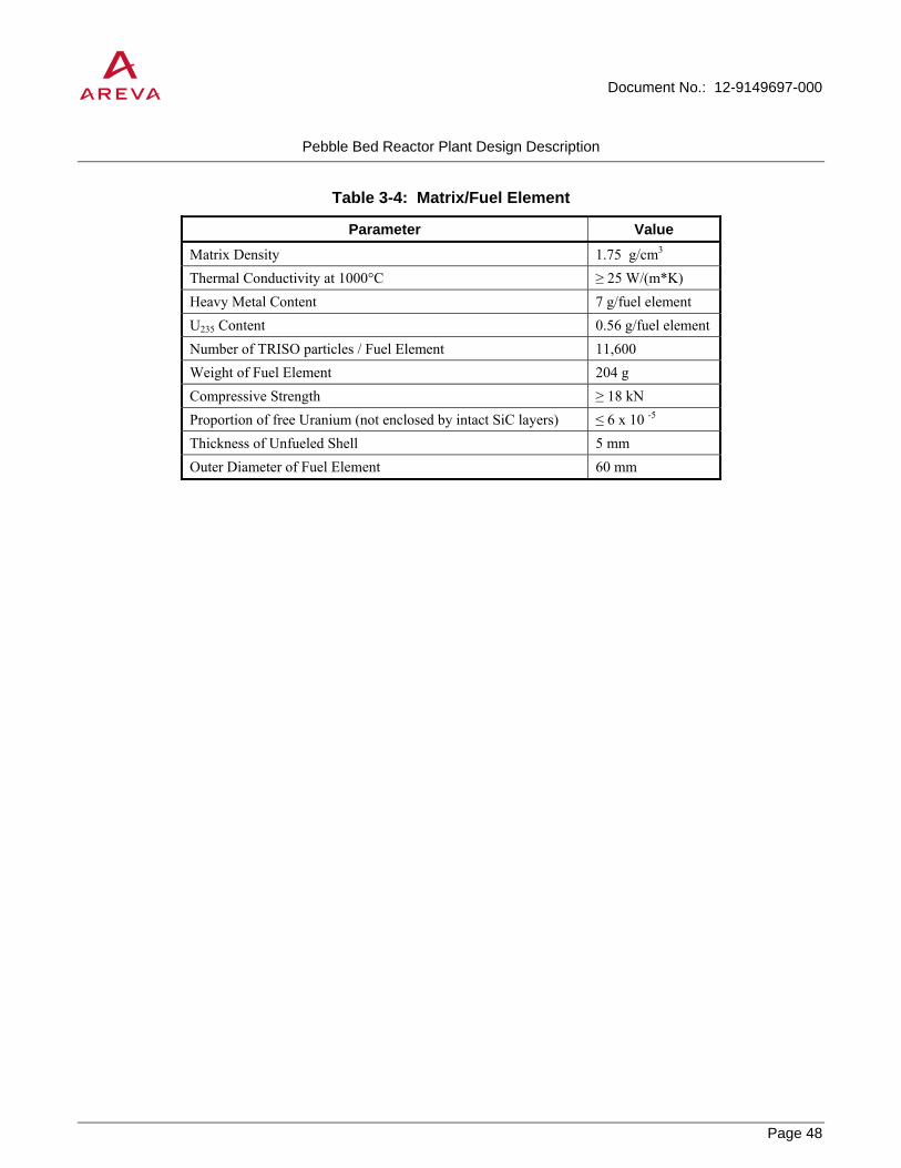
Document No.: 12-9149697-000
Pebble Bed Reactor Plant Design Description
Page 48
PROPRIETARY
Table 3-4: Matrix/Fuel Element
Parameter Value Matrix Density 1.75 g/cm3
Thermal Conductivity at 1000°C ≥ 25 W/(m*K) Heavy Metal Content 7 g/fuel element U235 Content 0.56 g/fuel element Number of TRISO particles / Fuel Element 11,600 Weight of Fuel Element 204 g Compressive Strength ≥ 18 kN Proportion of free Uranium (not enclosed by intact SiC layers) ≤ 6 x 10 -5 Thickness of Unfueled Shell 5 mm Outer Diameter of Fuel Element 60 mm

Document No.: 12-9149697-000
Pebble Bed Reactor Plant Design Description
Page 49
PROPRIETARY
Table 3-5: Nominal Data for Equilibrium Core
Parameter Value Thermal Power 200 MW Core Diameter 3 m Core Height (avg.) 9.4 m Power Density 3.0 MW/m3 Inlet Coolant Temperature (avg) 250°C Outlet Coolant Temperature (avg) 700°C Primary System Pressure 60 bar Number of Fuel Elements 360,000 Number of Radial Enrichment Zones 1 Number of Fuel Element Cycles 15 Reactivity Reserve for Load Cycle 1.2% Δk/k U235 Enrichment 8 ± 0.5 wt % Heavy Metal Charge 7 g / fuel element Fuel element dwell time (avg.) 1007 EFPDs Fuel Element Run Time per Cycle (avg.) 67 EFPDs Average Burnup 80,000 MWd/Mg U Overall Power Density Form Factor 1.8 Neutron Loss from Pebble Bed 13.7% Maximum Neutron Fluence at Side Reflector (E ≥ 0.1 MeV) 1.8 x 10²² neutrons/cm-2 Core Fuel Inventory Heavy Metal (excluding fission products) 2396 kg Fissionable Material 107 kg

Document No.: 12-9149697-000
Pebble Bed Reactor Plant Design Description
Page 50
PROPRIETARY
Table 3-6: Principal Data of Core Internals
Parameter Value Overall Height of Ceramic Core Structure 17 m Outside Diameter 5 m Inside Diameter (core diameter) 3 m Mean Core Height 9.4 m Thickness of Side Reflector 1 m Height of Core Bottom 2.5 m Angle of Core bottom 30 degrees Height of Top Reflector 2.5 m Overall height of Core Barrel 19.2 m Core Barrel Outside Diameter 5.7 m Design Temperature of the Core Barrel 500°C Diameter of Hot Gas Duct 0.75 m Number of Reflector rods 6 Number of Small Ball Shutdown Units 18 Number of Fuel Feed Tubes 1 Number of Fuel Discharge Tubes 1

Document No.: 12-9149697-000
Pebble Bed Reactor Plant Design Description
Page 51
PROPRIETARY
Table 3-7: Principal Data of Reflector Rod Control Shutdown System
Parameter Value Absorber Length approx. 4800 mm Absorber Diameter approx. 100 mm Absorber Material B4C rings Cladding Material X8CrNiMoNb 1616 Maximum travel approx. 6750 mm Normal Speed approx. 1 cm/s

Document No.: 12-9149697-000
Pebble Bed Reactor Plant Design Description
Page 52
PROPRIETARY
Table 3-8: Principal Data for the Small Ball Shutdown System
Parameter Value
Ball Diameter approx. 10 mm Absorber material B4C in graphite matrix Percentage of B4C 10% by volume Drop Height max. 15 m Number of Units 18 Dimensions of side reflector slotted holes approx. 260 x 60 mm Number of small ball shutdown elements per side reflector slot 2.4 x 10⁵
Drop time for full charge pneumatic return approx. 1 minute Forwarding time (minimum) for total charge per side reflector slotted hole 3 minutes Circulator Capacity (maximum) 12 kW

Document No.: 12-9149697-000
Pebble Bed Reactor Plant Design Description
Page 53
PROPRIETARY
Figure 3-2: Fuel Element

Document No.: 12-9149697-000
Pebble Bed Reactor Plant Design Description
Page 54
PROPRIETARY
Figure 3-3: Maximum Failed Particle Fraction as a Function of Temperature

Document No.: 12-9149697-000
Pebble Bed Reactor Plant Design Description
Page 55
PROPRIETARY
Figure 3-4: Longitudinal Section through Reactor

Document No.: 12-9149697-000
Pebble Bed Reactor Plant Design Description
Page 56
PROPRIETARY
Figure 3-5: Reactor Cross-Sections (1)

Document No.: 12-9149697-000
Pebble Bed Reactor Plant Design Description
Page 57
PROPRIETARY
Figure 3-6: Reactor Cross-Sections (2)

Document No.: 12-9149697-000
Pebble Bed Reactor Plant Design Description
Page 58
PROPRIETARY
Figure 3-7: Reactor Cross-Sections (3)

Document No.: 12-9149697-000
Pebble Bed Reactor Plant Design Description
Page 59
PROPRIETARY
Figure 3-8: Reflector Rod Drive Mechanism

Document No.: 12-9149697-000
Pebble Bed Reactor Plant Design Description
Page 60
PROPRIETARY
Figure 3-9: Small Ball Shutdown System

Document No.: 12-9149697-000
Pebble Bed Reactor Plant Design Description
Page 61
PROPRIETARY
Figure 3-10: Axial Power Density Profile – Equilibrium Core

Document No.: 12-9149697-000
Pebble Bed Reactor Plant Design Description
Page 62
PROPRIETARY
Figure 3-11: Axially Averaged Power Density Profile – Equilibrium Core

Document No.: 12-9149697-000
Pebble Bed Reactor Plant Design Description
Page 63
PROPRIETARY
Figure 3-12: Axial Power Density Profile – First Core
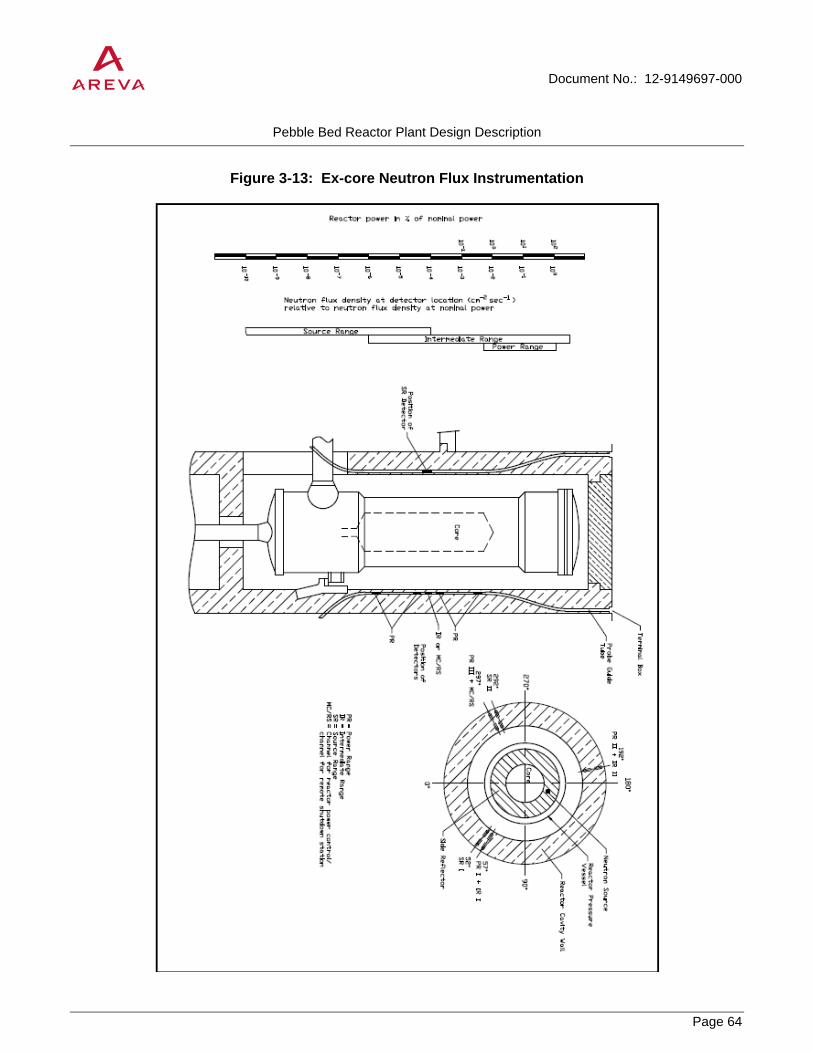
Document No.: 12-9149697-000
Pebble Bed Reactor Plant Design Description
Page 64
PROPRIETARY
Figure 3-13: Ex-core Neutron Flux Instrumentation

Document No.: 12-9149697-000
Pebble Bed Reactor Plant Design Description
Page 65
PROPRIETARY
3.3 Primary Circuit Components
3.3.1 Primary Circuit Description
The HTR-Module power plant consists of two reactor / steam generator pairs having a nominal thermal power of 200 MW each and sharing some of the same systems. Each primary circuit consists of:
• The reactor pressure vessel with core, core internals, shutdown systems and systems for feeding and discharging fuel elements
• The gas duct pressure vessel with hot gas duct
• The steam generator with tube bundle and main circulator
3.3.1.1 System Specific Design Features
The selected core dimensions and the limitation of mean power density to 3 MW/m3 restrict the temperature of fuel elements in the HTR-Module to approximately 1600°C in all accidents and combinations of accidents, regardless of the operability of the cavity cooler. This rules out significant degradation of fuel particles and unacceptable releases of fission products from the fuel elements.
This is the salient characteristic of the HTR-Module’s primary circuit which brings about the following features:
• Residual heat can be removed to the cavity cooler located on the reactor cavity wall by thermal conduction, thermal radiation and natural circulation under all operating and accident conditions.
• The cavity cooler alone is able to protect core internals, shutdown systems, the reactor pressure vessel and the concrete structure of the reactor cavity from unacceptable temperatures under all accident conditions.
• The location of the shutdown systems in the side reflector assures that they do not sustain unacceptable thermal loadings and thus their operability cannot be impaired.
• There is no danger of primary coolant causing metallic components to overheat on failure of the main circulator, even if the circulator damper fails to close, because component arrangement and primary coolant circulation is such that, with the reactor being higher than the steam generator, natural circulation in the primary system which could result in damage to metal parts is prevented. This arrangement allows the steam generator to be cooled irrespective of the core temperature.
The following components constitute the pressure vessel unit:
• Reactor pressure vessel, including:
o nozzles, closure head
o fuel discharge tube with forged fuel separator block
o connecting line for fuel feed equipment including valve bank

Document No.: 12-9149697-000
Pebble Bed Reactor Plant Design Description
Page 66
PROPRIETARY
o connecting lines for small ball shutdown units, including valve banks
o electrical and I&C penetrations
• Steam generator pressure vessel, consisting of steam generator and main circulator pressure vessel portions, including
o nozzles, cover
o main steam and feedwater nozzles with connecting nozzles of secondary-side systems
o electrical and I&C penetrations
• Gas duct pressure vessel
The following items constitute the primary gas envelope, which has the function of enclosing the primary coolant and limiting air and water inleakage:
• Pressure vessel unit, excluding parts of the main steam and feedwater nozzles which are exposed to secondary fluid only
• Steam generator tube bundle with tubesheets for main steam and feedwater
• Primary-side connecting lines up to and including primary system isolation valve
The stringent quality requirements applied to the reactor pressure vessel, the gas duct pressure vessel and the steam generator pressure vessel and the prevention of non-ductile failure assure that core geometry is maintained and, thus, that design temperature of fuel elements is inherently limited to approximately 1600°C.
The primary circuit fulfills the following operational requirements:
• The equilibrium core is designed for unrestricted load cycling operation between 100% and 50% of nominal load. The necessary reactivity of approximately 1.2% is provided by the reflector rods
• Hot startup is possible for a period of approximately 1 hour after scram due to malfunction; a power level of at least 45% can be achieved after approximately 1.5 hours. If the cause and consequences of the scram cannot be remedied in this period, the rapidly increasing xenon poisoning of the core prevents restart for a period of approximately 24 hours.
3.3.1.2 System Description
Figure 3-14 shows the primary system layout of the HTR-Module equipped with a steam generator. The thermal output of 200 MW generated in the reactor core is removed by the primary coolant helium which flows through the core from top to bottom. The hot helium leaving the reactor core at 700°C is conveyed along a horizontal hot gas duct to the steam generator where it flows through the tube bundle there, likewise from top to bottom; in so doing, it is cooled down and then passes through the annular gap between steam generator shroud and pressure vessel wall to the main circulator located in the upper portion. The cold gas leaving this circulator returns through the coaxial gas duct pressure vessel around the hot gas duct to the lower region of the reactor pressure vessel, then flows back to above the reactor core through columns in the graphitic side reflector.

Document No.: 12-9149697-000
Pebble Bed Reactor Plant Design Description
Page 67
PROPRIETARY
Feedwater and steam flow through the heat exchange tubes of the steam generator upwards in counterflow to the primary coolant. The main steam thus generated has a temperature of 530°C and a pressure of 190 bar.
The location of the steam generator to the side of and lower than the reactor pressure vessel allows upward evaporation, which has operational advantages, and the location of the main circulator in the upper portion of the steam generator pressure vessel, which provides ease of access. Because of the flow circulation pattern, only limited portions of the pressure vessel unit are exposed to hot gas. It is thus possible to use pressure vessel technology proven in light water reactors. This also applies to the feedwater nozzle. The main steam nozzle and the steam generator bundle, which are exposed to higher temperatures, are made using proven conventional technology and high temperature reactor/fast breeder technology.
The helium used as the primary coolant cannot be activated except for the small He-3 fraction.
Contaminants entering the primary coolant are constantly removed during operation by a helium purification system.
Contaminant concentrations during normal operation are similar to that in the AVR and the Peach Bottom Reactor:
• H2O less than 0.1 vpm
• H2 less than 5 vpm
• CO less than 2 vpm
• CO2 less than 0.5 vpm
• CH4 less than 1 vpm
• N2 less than 1 vpm
The accident-induced increase in the concentration of CO2 and H2O is limited in order to prevent excessive graphite corrosion.
3.3.1.3 Leak-Tightness and Leakage Monitoring
3.3.1.3.1 Leak-Tightness
As a rule, the pressure vessel unit and all adjoining piping systems are welded leak-tight.
Flanged connections on the steam generator pressure vessel are provided with welded-lip seals or metal ring gaskets. The flanged connections of the RPV closure head and the circulator cover are sealed with double metal ring gaskets. Leak tests are conducted after every assembly to ensure that the system is leak-tight.
3.3.1.3.2 Leakage Monitoring of the Pressure Vessel Unit
During power operation, the air in the primary cavity is monitored which would indicate the presence of leaks in the vessels. The measured variable is in thermal conductivity which differs between helium and air. A gas mixture is constantly extracted from the exhaust air duct of the subatmospheric pressure system and conveyed to a

Document No.: 12-9149697-000
Pebble Bed Reactor Plant Design Description
Page 68
PROPRIETARY
monitor. Because the air change rate in the primary cavity is low, even small leaks (corresponding to leak cross-section of 1 mm²) produce a relatively high concentration of helium; conventional measuring instruments are therefore sufficiently precise. Convection in the primary cavity during power operation causes thorough mixing of the gas, with the result that the helium concentration at the measurement location follows that of the primary cavity after a delay.
3.3.1.3.3 Monitoring of Water/Steam Leakages
In the rooms allocated to the main steam nozzle and to the feedwater nozzle, the humidity of the air is monitored. In the equipment compartments, leakages corresponding to a cross-section of 10 mm2 can be detected.
3.3.2 Reactor Pressure Vessel (RPV)
3.3.2.1 Function and Description
The reactor pressure vessel (RPV) houses the internals and the reactor core and is part of the primary gas envelope. The primary coolant enters the lower portion of the vessel through the nozzle from the gas duct pressure vessel, enters the core internals, flows upwards through cold gas columns in the side reflector of the ceramic internals, is redirected at the top, flows downwards through the reactor core and leaves the vessel through a pipe (hot gas duct) which is coaxial with the nozzle of the gas duct pressure vessel.
The lower portion of the RPV is insulated on the outside below the pebble bed. The insulation can be removed for inservice inspections.
Principal data for the reactor pressure vessel are summarized in Table 3-9.
3.3.2.2 Mechanical Design
The RPV consists of vessel portion, closure head and nozzles.
The vessel portion consists from bottom to top of the following forgings which are connected to each other by welded joints:
• The bottom, consisting of a crown with 5 nozzle penetrations and one manway, as well as a single-piece bottom reinforcement ring
• A reinforced shell course (support lug course) bearing gas duct pressure vessel nozzle and support lugs for supporting the RPV
• A reinforced shell course (internals support ring) for supporting core internals
• The cylindrical shell, consisting of 3 courses
• The upper reinforced course with outside horizontal stops and inside stops for the core barrel guide pads and various nozzles
• A shell flange for mounting the closure head as the top cover

Document No.: 12-9149697-000
Pebble Bed Reactor Plant Design Description
Page 69
PROPRIETARY
The center of the bottom is penetrated by a large nozzle for the fuel discharge tube. The fuel discharge tube with the forged failed fuel separator block is welded to this nozzle.
The following are located on one pitch circle:
• 1 nozzle for the fuel feed system
• 3 nozzles for the small ball shutdown system
• 1 integral flange with a blanking plate as a manway.
The support lug course bearing the gas duct pressure vessel nozzle and support lugs is reinforced to take the load and to provide reinforcement of the opening. The gas duct pressure vessel nozzle, likewise reinforced, and the 3 support lugs are attached to the outside.
The adjacent internals support ring supports the core internals and is provided with a sealing surface to form a seal with the core barrel.
There is a nozzle in the lowermost of the three courses of the cylindrical shell for connection of the pressure equalizing system to the region of stagnant helium between core barrel and RPV.
The reinforced course connected to the cylindrical shell contains the horizontal supports, the stops for the core barrel guide pads, nozzles with prestressed glass penetrations for power supply to the control systems and instrumentation.
The shell flange at the top of the vessel accommodates the studs for bolting down the RPV closure head. It also has a clad mating surface for sealing the closure head. There are holes from the sealing surface to the outside at two locations on the circumference for leakage monitoring. Permanent monitoring is not provided.
The reactor pressure vessel closure head consists of two forgings jointed by welding:
• The closure head flange
• The closure head dome plate
The underside of the closure head flange is clad to form a sealing surface and contains two grooves which receive metal rings as sealing elements between reactor closure head and vessel. Three lifting eyes are welded to the closure head dome plate.
The closure head is bolted to the vessel body by means of 70 studs, washers and nuts. The studs are of the scant shank type screwed into blind tapped holes in the RPV flange ring
The nuts and washers have convex mating surfaces in order to ensure favorable load distribution. Two concentric metal ring gaskets provide a tight seal between vessel body and closure head.
The closure head can be removed with the two ring gaskets for the purpose of interior inspection.
Core internals are described in 3.2.3.

Document No.: 12-9149697-000
Pebble Bed Reactor Plant Design Description
Page 70
PROPRIETARY
3.3.2.3 Manufacture
The RPV is manufactured from hot-formed crowns and seamless forged rings, flanges and nozzles. Small nozzles are produced from bar stock, while lugs and stops are made of plate. The ingots for these forms are smelted in an electric arc furnace and vacuum cast to achieve extra purity and uniformity of the steel.
After hot forming or forging, the individual product forms are quenched and tempered to achieve the necessary mechanical properties. After quenching and tempering, the weld edge preparations and surfaces of the rings are machined. They are then assembled by welding girth and nozzle joints, support lugs and guides are attached; this is followed by heat treatment and final machining. Manufacture of the RPV is concluded with nondestructive examination after the pressure test.
3.3.2.4 Operational Safety
Non-ductile fracture of the reactor pressure vessel is prevented by the following measures:
• Reliable analysis of operational loadings and conservative limitation of resulting stresses
• Use of optimized steel with good toughness and small susceptibility radiation embrittlement. Use of production methods which limit manufacturing error to an insignificant level
• Quality assurance through review by individuals independent of the production organization of design, selection of materials and fabrication sequence, and independent destructive testing and non-destructive examination of material and production test specimens and non-destructive examination of the entire reactor pressure vessel. Integral verification of safety by pressure tests on the finished vessel
• Inservice ultrasonic examination of the vessel. Inservice pressure testing independent of this.
Stresses forming the basis for structural analysis of the pressure vessel are substantially less than ultimate stresses.
Ultrasonic examination and pressure testing are especially important for pressure vessel safety. Ultrasonic examination is a volumetric method; by contrast, pressure testing is an integral method (see 3.3.9).
3.3.3 Gas Duct Pressure Vessel and Hot Gas Duct
3.3.3.1 General
The gas duct pressure vessel and the coaxial hot gas duct serve to convey the primary coolant between the reactor pressure vessel and the steam generator pressure vessel.
Hot gas flows from the reactor outlet to the steam generator in the hot gas duct; cold gas flows from the gas outlet nozzle of the steam generator pressure vessel to the inlet nozzle of the RPV in the annulus between the gas duct pressure vessel and the hot gas duct.
The vessel consists of a seamless forged ring welded to the nozzle of the RPV and the steam generator pressure vessel. It is insulated on the outside.
Working radially outwards from the inside the straight hot gas duct is constructed as follows:

Document No.: 12-9149697-000
Pebble Bed Reactor Plant Design Description
Page 71
PROPRIETARY
• Metal pipe to guide the hot gas flow and to protect the insulation material from direct fluid flow loadings
• Wound fiber mats with radial convection barriers
• Metal support pipe acting as load-bearing member and as seal between the hot and cold gas regions
Bellows expansion joints compensate for displacements caused by thermal expansion of the hot gas duct.
3.3.3.2 Gas Duct Pressure Vessel
The gas duct pressure vessel is located between the reactor pressure vessel and steam generator pressure vessel. These three components together constitute the pressure vessel unit. The hot gas duct is located within the gas duct pressure vessel. The gas duct pressure vessel and the hot gas duct constitute the coaxial gas passage for the primary coolant between reactor and steam generator.
The gas duct pressure vessel consists of a seamless forged ring. It is made of the material 20 MnMoNi 5 5 and is welded to the nozzles of the reactor pressure vessel and the steam generator pressure vessel.
Design data are summarized in Table 3-10.
3.3.3.3 Gas Duct Pressure Vessel Internals
3.3.3.3.1 Function
The hot gas duct is located within the gas duct pressure vessel. Design data are summarized in Table 3-11.
The hot gas duct connects the reactor with the heat-exchange component. The hot primary coolant leaves the hot gas plenum below the reactor core, enters and passes through a horizontal duct and is redirected 90 degrees downward in the head of the steam generator.
The primary coolant flows from the main circulator back to the reactor in the gap between the gas duct pressure vessel wall and the hot gas duct after it has cooled down.
3.3.3.3.2 Component Description
Radially, the straight hot gas duct (Figure 3-15) is as follows constructed from the inside outwards:
• Metal gas pipe to guide the flow of hot primary coolant and protect the fiber material from direct fluid flow loadings
• Wound fiber mats with radial convection barriers
• Metal support pipe acting as load-bearing member and providing a leak-tight barrier between hot and cold gas; it is located the cold gas side and is subject only to the differential pressure between cold and hot gas
The support pipe is bolted to the core barrel by means of a transition flange. The pipe consists of two pipe segments welded together. A packed fiber gasket which ensures a high pressure loss is used to create as tight a connection as possible between core structure and hot gas duct and thus to protect the insulation in the connection region from high through-flow. The ceramic core internals are extended into the transition flange in the form of a

Document No.: 12-9149697-000
Pebble Bed Reactor Plant Design Description
Page 72
PROPRIETARY
doweled graphite pipe, which allows the fiber packing to be located between the graphite pipe and the transition flange.
Due to the coaxial arrangement, the graphite pipe is subject only to the differential pressure of the primary system. The coaxial flow also keeps it at a low temperature. It is thus a low-stress item.
Two bellows expansion joints are built into the near-core portion of support pipe. Like the support pipe, they are subject only to system differential pressure. The displacements requiring compensation are slight. Conservative design is simple for the number of cycles concerned. The high elasticity of the joints results in only slight restoring forces.
The insulation is divided into several courses for ease of assembly. Each course contains a vee-ring between the gas pipe and the support pipe to hold the gas pipe. These vee-rings (convection barriers) form an elastic joint for absorbing radial expansion; they also prevent axial flow through the insulation.
The insulation in the area is not disturbed by these vee-rings consists of wound Al2O3 fiber mats. The insulation around the vee-rings is made of packed Al2O3 fiber. Insulation at the joints between the insulation courses consists of cross-ply fiber insulation rings to absorb axial expansion.
The hot primary coolant is redirected towards the steam generator tube bundle in the elbow adjoining the hot gas duct. Self-supporting fiber block insulation is used. To prevent pressure differentials in the redirecting area, a closed elbow is located in front of the insulation to direct the flow. Baffles are provided for a uniform flow velocity profile in the elbow.
The hot gas duct is designed for the service life of the reactor.
3.3.3.4 Inspection
The operational instrumentation of the primary system (mass flow and temperature measurements of the ceramic internals) provides monitoring of the hot gas duct. Inservice inspections are not envisaged.
In principle, it is possible to perform repairs or replacements.
3.3.4 Steam Generator Pressure Vessel and Internals
3.3.4.1 General
The steam generator transfers heat from the primary coolant (helium) to the water/steam cycle and generates main steam to drive the turbine generators and/or to generate process steam.
The steam generator consists of the steam generator pressure vessel and internals. It is arranged vertically next to the reactor pressure vessel and connected to it by the gas duct pressure vessel.
The primary coolant helium enters and leaves the steam generator coaxially through the hot gas duct and the gas duct pressure vessel.
Feedwater enters through the feedwater nozzle located on the side at the bottom of the steam generator pressure vessel. The main steam nozzle is on the side at the top of the steam generator pressure vessel. The main

Document No.: 12-9149697-000
Pebble Bed Reactor Plant Design Description
Page 73
PROPRIETARY
circulator for circulating the primary coolant is integrated into the upper portion of the steam generator pressure vessel.
The overall primary coolant flow pattern is laid out in such a way that the steam generator pressure vessel comes into contact with cold helium only.
Table 3-12 contains operational data for the steam generator.
3.3.4.2 Structure and Principle of Operation
Figure 3-16 gives an overall view of the steam generator pressure vessel and heat exchanger.
The steam generator is a forced circulation once-through heat exchanger with helical tubes. Heating is provided by helium flowing downwards through the tube bundle (shell side) between the central pipe and the tube wrapper. The feedwater is evaporated and superheated as it flows upwards inside the tubes.
The hot helium enters the steam generator through a radial nozzle on the side of the steam generator pressure vessel (Figure 3-17). A flow deflector assembly, which consists of an elbow, annular louvers, and a louver-like inlet, is provided to redirect the hot helium downwards from the lateral inlet. Baffles are welded into the elbow to create a balanced flow profile.
The hot gas flow broadens into the tube bundle through annular louvres which uniformly redirect the elbow flow radially. This uniform radial flow is then deflected into the bundle by a louvre-like inlet which ensures that the flow pattern is uniform across the diameter.
The helium then flows through the tube bundle between the central pipe and the tube wrapper while transferring its heat to the water/steam cycle and consequently cools down from approximately 700°C to approximately 245°C.
When leaving the tube bundle, the helium flow is deflected through 180 degrees. The cold helium then flows upwards between the steam generator shroud and the pressure vessel wall; the temperature of the pressure vessel is thus governed by the cold gas temperature. To reduce heat exchange between the bundle flow and the return flow, the gas-tight gap between tube wrapper and steam generator shroud is thermally insulated.
The returning helium is collected in a cold gas header at the upper end of the steam generator shroud, from which it proceeds to the main circulator through cold gas lines. These lines open into a circulator inlet chamber which ensures uniform inflow.
From the circulator, the helium returns to the coaxial gap of the gas duct pressure vessel through the top plenum of the steam generator pressure vessel and then back to the reactor.
The feedwater enters the steam generator at the bottom through the lateral feedwater nozzle. From there, it is distributed over a tubesheet to the tubes leading to tube bundle. To improve flow stability and the steam temperature profile, removable flow restrictors are provided ahead of the tubesheet. The water flows from bottom to top through the helical tubes, where it is evaporated and then superheated. The steam reaches the main steam nozzle through an expansion tube bundle above the tube bundle.

Document No.: 12-9149697-000
Pebble Bed Reactor Plant Design Description
Page 74
PROPRIETARY
3.3.4.3 Steam Generator Pressure Vessel
The steam generator pressure vessel consists of a steam generator pressure vessel portion and a circulator pressure vessel portion.
The steam generator pressure vessel portion consists from bottom to top of the following parts which are welded together:
• The bottom head with a manway.
• The reinforced bottom forged ring bearing the butt-welded feedwater nozzle, exterior seismic supports and stops.
• The lower cylindrical shell which consists of a seamless forged ring.
• A reinforced reducer ring to support the cold gas header and to reduce the diameter from the upper to the lower shell courses.
• The reinforced, upper shell consisting of a seamless forged ring bearing the main steam nozzle, the nozzle to the gas duct pressure vessel and two support lugs and one guide lug.
• An upper flanged ring as the top element of the vessel.
• Nozzles for instrumentation, for assembly, for inspection and for the passage of helium to and from the helium purification system.
The torispherical bottom head has a nozzle with a blanking flange and a welded-lip seal for use as a manway.
The offset ring supports all the bundle internals and provides a transition between the different diameters of the lower and upper courses of the steam generator pressure vessel portion.
The forged ring of the upper cylindrical shell bearing the nozzle for the gas duct pressure vessel, the main steam nozzle, an instrumentation nozzle and the nozzle for returning helium to the helium purification system, as well as support lugs for the sliding support and the stop for a link, are reinforced because of the loads to be borne and because of the large nozzle openings. All nozzles are welded into the shell, the main steam nozzle being butt-welded around a thermo-sleeve. The support lugs and the stop for the guide are mounted on the outside.
The uppermost flange ring of the steam generator pressure vessel portion accommodates the studs for bolting down the circulator pressure vessel portion.
The circulator pressure vessel portion consists of the following parts:
• A flange ring integral with another ring which forms the inner flange for supporting the main circulator.
• A cylindrical shell bearing various nozzles for penetrations, integral with a cover flange.
• The cover consisting of a flange ring and a cover crown plate.
Table 3-13 contains principal design data for the steam generator pressure vessel.

Document No.: 12-9149697-000
Pebble Bed Reactor Plant Design Description
Page 75
PROPRIETARY
3.3.4.4 Tube Bundle
The tube bundle consists of helical tubes connected individually to the feedwater and main steam tube sheets by connecting tubes. The feed water is fed in via orifices. The helical tubes are arranged in cylindrical planes at constant radial distances from the central pipe. The number of tubes per cylinder and their longitudinal pitch are chosen in such a way that all the tubes are of almost the same length. The number of tubes is such that sufficient spare heat exchange surface capacity is available in case damaged tubes have to be plugged. Tube bundle parameters are identified in Table 3-14.
The individual tubes of the main tube bundle are positioned by three radial tube support plates which are fixed at the inner flow shroud. Inner and outer shroud are connected by six radially arranged support beams. The outer flow shroud itself serves therefore as the main carrier of the tube bundle and is supported by the reinforced inner flange of the pressure vessel.
For reasons of limiting flow induced vibration loads, the outer 16 rows of the tube bundle are positioned with 3 x 2 additional so called "floating" spacer plates. The “floating” arrangement is necessary in order to minimize thermal stresses due to differences in temperature between support structure and tubes.
When assembling the tube bundle, the already coiled individual tubes have to be screwed through the pre-positioned support plates. Inside the support plate bores the tubes are fixed by a special clamping device. The tube is surrounded by two conical half shells and is finally positioned by an additional cartridge. Half shells and cartridge are clamped elastically together. An additional fixation by welding points is possible.
The tube material is X10NiCrAlTi 32 20 (Alloy 800) because of its good mechanical properties at high temperatures and because of its resistance to corrosion. The tube walls are thinner in the lower temperature region than in that of higher temperatures because of the material’s higher mechanical values. The outside diameter of the tubes is constant over their entire length.
The tubes and tube sheets are designed for a service life of 32 full-load years (based on KTA design rules). The design pressure is the maximum pressure differential between the two working fluids under normal operating conditions. The short-term pressure differential between the working fluids in the event of a primary-side depressurization accident is also considered. The design temperature is the maximum mean tube wall temperature.
For calculations, an allowance of 50 K is added to the helium temperature and an allowance of 40 K to the steam temperature for tilts and inaccuracies of the instrumentation and control system. An allowance of 10% is added to the required tube wall thickness to account for thickness tolerances. No allowance is added for corrosion.
3.3.4.5 Other Internals
The support plates are connected to the steam generator shroud at the lower cold end, which results in the bundle weight and forces from external events being taken by the steam generator shroud in this region. The shroud is suspended from the steam generator pressure vessel by a flange construction at its upper end.
The insulating gap cylinder is a cylindrical shell between tube wrapper and steam generator shroud arranged in such a way that a gas-tight gap exists between it and the steam generator shroud. Thermal insulation is applied between the insulating gap cylinder and the tube wrapper and consists, as in the hot gas duct, of aluminum oxide fiber. This insulating gap opens into the top plenum of the steam generator pressure vessel portion containing cold gas from the delivery side of the main circulator. With this arrangement, only cold primary coolant can reach the pressure vessel wall in case of leaks in the steam generator shroud.

Document No.: 12-9149697-000
Pebble Bed Reactor Plant Design Description
Page 76
PROPRIETARY
In order to assure proper boundary flow in the bundle, the tube bundle is surrounded by a tube wrapper made to tight tolerances. At the bottom, this tube wrapper is welded leak-tight to the steam generator shroud to prevent primary coolant bypass flows.
The tube bundle is connected to the tubesheets by expansion tubes. Their function is to connect each tube to the tubesheets in such a way as to compensate for relative movement between tube bundle and tubesheets.
The expansion tubes have the same inside diameter as the connected heat exchange tubes to allow interior inspection of the tubes. Main steam expansion tubes are insulated above the steam generator shroud to prevent heat loss to the surrounding cold helium.
3.3.4.6 Water/Steam Connections
The transition from the pressure vessel material 20 MnMoNi 5 5 to the main steam line material X20 CrMo V 121 is made of an intermediate piece of X10 CrMo 9 10. On the steam side the tube plate, made of X10 NiCrAlTi 32 20 (Alloy 800), is connected to the main steam line via an additional Alloy 800 transition piece.
This allows the final mounting of the tube bundle on site without having any transition welds there. To allow a still smoother transition, special buttering between several material combinations is recommended. To minimize thermal loading the annulus between inner and outer part of the thermal sleeve will be insulated.
The removable special flange design allows an easy access to the tube plates for inservice inspection purposes.
Tubesheets are provided for water inlet and main steam outlet in order to provide access for inspection or for plugging damaged tubes. These sheets are accessible after the feed water or main steam nozzle has been opened.
The sheets are made of material X10 NiCrAlTi 32 20 (Alloy 800) in order to allow the tube-to-tubesheet welds to be homogenous. The tubesheets are connected to the steam generator pressure vessel by a thermo-sleeve construction. This is calculated to prevent acceptable temperatures from being exceeded. Dissimilar metal welds are required because of the change of material.
3.3.4.7 In-service Inspections and Repair of Steam Generator Tubes
The steam generator does not have a safety-relevant function regarding residual heat removal. However, the primary helium moisture content is monitored to avoid water ingress inside the core from leakage of the tube bundle.
To guarantee high availability, an inspection of the water/steam containing parts is possible:
• The tube plates are accessible for examinations from the secondary side.
• The inside of steam generator tubes is accessible for sounding probes from the tube-sheets after opening the closures of the feedwater and main steam nozzles. In the event of tube damage, plugs can be welded into both ends of the damaged tube.
Examination intervals of 8 years for pressure tests and 4 years for non-destructive tests are foreseen.

Document No.: 12-9149697-000
Pebble Bed Reactor Plant Design Description
Page 77
PROPRIETARY
3.3.5 Vessel Supports
3.3.5.1 General
The supports for the RPV and the steam generator pressure vessel are located at the level of the central axis of the gas duct pressure vessel. Three radially guided support lugs set 120° apart around the RPV take the load and secure hold the vertical axis of the RPV in place. Below the closure head flange are stops which ensure the stability of the pressure vessel unit during external events.
The load of the steam generator pressure vessel is taken by sliding bearings which allow horizontal displacement in line with the gas duct pressure vessel, which is welded to the RPV. Horizontal forces exerted by the gas duct pressure vessel are absorbed at this level. Likewise, the lower end of the steam generator can travel along gas duct pressure vessel axis. Shock loads due to external events are absorbed by snubbers.
3.3.5.2 Functions and Requirements
The reactor pressure vessel (RPV) and the steam generator pressure vessel are braced against the reinforced concrete structure of the reactor cavity by the supports. The support construction fulfills the following requirements:
• The supports at the level of the gas duct pressure vessel allow radial and axial thermal expansion of the RPV due to the effect of temperature while holding the longitudinal axis of the RPV in place
• They also allow radial and axial thermal expansion of the steam generator pressure vessel while allowing displacement due to thermal expansion of the gas duct pressure vessel
• Suitable design features prevent the supports from transferring unacceptable amounts of heat to the concrete structures
3.3.5.3 Supports
The RPV and the steam generator pressure vessel, which are located at different heights, are supported in three planes in all.
The middle support plane at the level of the gas duct pressure vessel absorbs vertical and horizontal forces, while the upper and lower support planes absorb only horizontal forces in order to allow thermal longitudinal expansion of both components.
3.3.5.3.1 RPV Middle Support Plane
Three I-shaped lugs are welded onto the RPV at uniform intervals around its circumference. Each of these rests on a sliding support which allows radial expansion of the RPV.
In order to hold the RPV along its vertical axis in place, each lug is guided radially from above by a fitted taper key.
One support pad is provided for each of the three lugs and this accepts the sliding support and the taper key. The support pads are supported on the concrete structure by a lower diagonal and an upper horizontal bearing. The

Document No.: 12-9149697-000
Pebble Bed Reactor Plant Design Description
Page 78
PROPRIETARY
upper horizontal bearing is a sliding support in order to allow thermal expansion of the support pad. Anchor ties on both bearings clamp the support pads on to the concrete.
The support pads are provided with cooling system to reduce the flow of heat from the support lugs to the concrete structure through the support pads.
3.3.5.3.2 Upper Support Plane of the RPV
Four guides are arranged evenly around the circumference of the RPV in the upper support plane to support it horizontally against the concrete structure in the event of induced vibrations.
Each link is mounted on the primary cavity wall by a clevis bracket and tensioned anchor ties. They do not impede thermal expansion of the RPV as the pins connecting the links to the RPV and the clevis bracket have spherical bearings. Attachment-welded stops provide the connection to the RPV.
3.3.5.3.3 Middle Support Plane of the Steam Generator Pressure Vessel
Two I-shaped lugs are welded onto the steam generator pressure vessel at the level of the gas duct pressure vessel. They are arranged perpendicular to the longitudinal axis of the gas duct pressure vessel.
The lugs rest on sliding supports which allow radial thermal expansion of the steam generator and horizontal displacement of the steam generator pressure vessel by the gas duct pressure vessel.
The steam generator pressure vessel is guided by a link arranged at a tangent to the steam generator and perpendicular to the gas duct pressure vessel on the same plane.
The sliding supports are borne by support pads as with the RPV.
These support pads are constructed in basically the same way as those provided for the RPV.
3.3.5.3.4 Lower Support Plane of the Steam Generator Pressure Vessel
Four snubbers are arranged at equal spacing around the circumference of the steam generator pressure vessel. They are arranged at a tangent and do not hinder thermal movement of the steam generator pressure vessel.
In case of induced vibrations, the snubbers lock and brace the steam generator pressure vessel horizontally on the concrete structure.
Each snubber is mounted on the primary cavity wall by means of a clevis bracket and anchor ties. They do not hinder axial thermal expansion of the steam generator pressure vessel since the pins connecting them to the steam generator pressure vessel and the clevis brackets are provided with spherical bearings. Attachment welded stops provide the connection to the steam generator pressure vessel.
3.3.6 Main Circulator
3.3.6.1 General Description
The main circulator is required to deliver and maintain an appropriate flow through the primary system according to the loading conditions during

Document No.: 12-9149697-000
Pebble Bed Reactor Plant Design Description
Page 79
PROPRIETARY
• Reactor power operation.
• Operational residual heat removal.
• Startup and shutdown operations.
The circulator is not needed for decay heat removal from a safety point of view but it provides normal decay heat removal with the steam generator. Main circulator trip is a safety-related function and is initiated by the reactor protection system on every reactor scram.
3.3.6.2 Component Description
The impeller is a single stage radial impeller overhung at the lower end of a vertical shaft. The compressor is driven by a variable-speed asynchronous motor. It can operate between 10% and 100% of its nominal speed.
The circulator is integrated into the top of the steam generator pressure vessel. The circulator and the motor are arranged in a unit with the vertical shaft in the circulator pressure vessel portion.
The main components of the circulator are identified on Figure 3-18. Design data is presented in Table 3-15.
3.3.6.2.1 Casing and Thermal Insulation
The main circulator is located at the top of the steam generator and connected to the pressure vessel by a transition flange. The intermediate flange (flange designed for 60 bars) separates the impeller from the motor compartment, i.e., the impeller, the diffusers, the suction casing and the circulator damper are exposed to the primary cold helium flow around 250°C. The parts located above the intermediate flange are in a primary coolant atmosphere at the primary circuit pressure but a lower temperature to preserve electrical components.
A thermal insulation above the intermediate flange and inside the lower part of the motor compartment operating at 60°C is necessary to reduce the heat ingress from the primary circuit at 250°C. Calculations have been performed to define the thermal insulation layer and its location.
Integrated water coolers prevent overheating of the motor winding.
Labyrinth seals provide adequate pressure balance in case of pressure differences.
3.3.6.2.2 Impeller
The impeller, with an outer diameter of 950 mm, is mounted at the lower end of the shaft.
Radially, at the impeller outlet, there are two diffusers. The first diffuser (outside diameter = 1500 mm) is connected to the intermediate flange and the second one to the main circulator pressure vessel portion.
3.3.6.2.3 Main Circulator Damper
The main circulator damper is located on the suction side of the circulator. The circulator damper has no safety-related functions but serves to reduce the thermal loadings and to protect components.

Document No.: 12-9149697-000
Pebble Bed Reactor Plant Design Description
Page 80
PROPRIETARY
The damper is fixed to the first diffuser (itself fixed on the intermediate flange). The closing time of the damper is approximately 10 seconds. The damper closes passively but an active closing device is also provided to assure a high reliability of the closing function.
3.3.6.2.4 Bearings
Integrated motor shaft oil bearings are provided on both sides of the motor. The technology is oil bath lubricated tilting pad journal bearings. The upper bearing is a combination of thrust and journal bearing while the lower bearing is only a journal bearing.
Magnetic bearings can be used as an alternative to the oil bath bearings. Refer to Section 6.1.5 for a discussion of magnetic bearings.
The lubricant from the oil bath is fed to the tilting pads by centrifugal force through radially drilled holes in the bearing sleeves, which are part of the motor shaft. Then, the oil flows back to the oil bath and is cooled.
The oil can be changed from outside the primary cavity when the primary system is fully pressurized and the main circulator shut down.
To avoid oil leakages into the motor compartment and thereby into the primary vessel, seals are provided on the bearing sleeve (floating seals and labyrinths). The escape of oil vapor through the labyrinth seals in the transition flange is negligible.
In case of oil leak from the oil baths, a catchment bath is located below the lower journal bearing.
At the lower bearing, a final oil thrower prevents any remaining leakage from entering into the main primary system.
3.3.6.2.5 Motor
The motor is submerged in the primary coolant (no requirement for high speed mechanical seals with this configuration) and cooled by the ambient helium, itself cooled by means of helium / water heat exchangers.
The motor compartment temperature must operate at 60°C. Thermal insulation is required to reduce the heat ingress from the primary circuit.
The motor is a three-phase asynchronous squirrel cage motor with a forged solid rotor (improves the rotor stiffness).The rotor winding consists in 4 three-phase systems and is fed by 4 constant current D.C. converters.
The electric power supply and instrumentation lines of the main circulator unit are run from the circulator pressure vessel portion to the outside through helium-tight pre-stressed glass cable penetrations.
3.3.6.2.6 Cooling
Several elements must be cooled:
• The bearings oil baths.
• The circulator motor chamber which has to be kept below 60°C.

Document No.: 12-9149697-000
Pebble Bed Reactor Plant Design Description
Page 81
PROPRIETARY
• The transition flange to reduce the heat ingress in the motor chamber.
The oil baths are cooled by water cooling coils fitted at the bottom of the baths.
The cooling of the motor compartment is achieved by a helium circulation thanks to the auxiliary impeller connected on the upper end of the motor shaft. The cooling is accomplished in the axial direction through cylindrical cooling ducts and in the rotor.
Helium / water heat exchangers ensure the helium cooling. The water cooling system is common to both the oil baths cooling and the helium cooling. The water pressure is around 10 bars but the system is designed to withstand the full operational pressure (60 bar). Water leakage into the circulator motor chamber can be ruled out during power operation because of the pressure difference to the water side.
3.3.7 Pressure Control and Relief
3.3.7.1 Pressure Control
The requirements for pressure control are derived from the necessity for controlling pressure during non-steady-state operation (e.g., part-load operation). During non-steady-state operation, primary system pressure changes only over a long period of time, making continuous feed-and-bleed unnecessary. Two-step action control within an upper and a lower limit maintains primary system pressure within the allowable operational limits.
Control of primary system pressure is realized by primary coolant feed-and-bleed through the helium purification system from and to the purified gas store.
To lower primary system pressure, a portion of the purified primary coolant can be let down to the purified gas store downstream of the second stage of the helium purification system. In normal operation the maximum possible mass flow to the purified gas store is 135 kg/h. Pressure can be lowered at a maximum of 3 bar/h.
If primary system pressure is too low, purified helium is fed into the primary system from the purified gas store.
The maximum rate is likewise 135 kg/h, corresponding to a maximum pressure increase of 3 bar/h.
A schematic diagram of the pressure control system is shown in Figure 3-19.
3.3.7.2 Pressure Relief System
The pressure relief system is shown in Figure 3-20. It protects the primary gas envelope from overpressure and is of two-train configuration.
A sufficient difference between the response pressures of the two trains and the operating pressure of the primary system prevents this system from responding during disturbances. Variations in pressure are handled by the operational pressure control system of the primary system. To minimize the outflow of primary coolant if a safety valve that has responded sticks open, the train concerned is automatically closed by the blocking valve after a maximum pressure decrease to approximately 8% below operational pressure.
Both trains of the primary system pressure relief system have a joint letdown line to the helium purification system ahead of the primary system isolation valve. The first train (small cross-section) blows down into the reactor building and then into the vent stack by way of the secured subatmospheric pressure system; the second

Document No.: 12-9149697-000
Pebble Bed Reactor Plant Design Description
Page 82
PROPRIETARY
train (larger cross-section) blows down into the reactor building, which can be relieved into the plant environment by way of the building's pressure relief system.
Each train contains the following components connected in series:
• Isolation valve interlocked with the isolation valve of the other train
• Blocking valve
• Safety valve
• Rupture disc
The response pressures are staggered in such a way that the second train does not open unless pressure continues to rise after the first train responds. The safety valves automatically reclose when pressure drops again. In the event pressure continues to drop due to leaks, the two blocking valves in the trains close themselves to prevent pressure from falling below 90% of operating pressure. At operating pressure (and higher), the blocking valves are open. The isolation valves upstream of these valves are closed only for maintenance, inspection and repairs, and are interlocked in such a way that the valve of only one train can be closed at a time.
The rupture discs downstream of the valves are provided merely for sealing against possible leaks in the affected train; they allow leakage monitoring in the area between safety valve and rupture disc.
Table 3-16 contains design data for the pressure relief system.
3.3.7.3 Pressure Equalizing System
The pressure equalizing system is shown in Figure 3-21. It protects the core barrel in the reactor pressure vessel from unacceptable differential pressure loadings and provides separation of the internal helium atmosphere from the surroundings when the reactor pressure vessel is opened and depressurized.
To equalize differential pressures across the core barrel, a connecting line which can be isolated externally is provided as 'an operational train from the primary system (connection: letdown line to helium purification system) to the reactor pressure vessel (RPV) above the seal (between pressure vessel and core barrel). The isolation valve is closed only after pressure has been reduced to ambient before opening of the reactor pressure vessel, e.g., for inservice inspections. This train also equalizes pressure in the event of loss-of-fluid accidents involving breaks up to approximately 30 mm in diameter in regions containing circulating helium and up to approximately 20 mm in regions containing stagnant helium. A connecting nozzle for the core barrel leak testing system is fitted between the isolation valve and the RPV.
To compensate for breaks of larger cross-section (up to DN 65, equivalent to a design-basis accident), an internal train is provided which opens an internal connection (inside diameter approximately 200 mm) between the core barrel and the region of the RPV containing stagnant helium on response of the associated rupture disc at a differential pressure above approximately 1 bar. Two rupture discs are arranged parallel and in counterflow in order to handle differential pressure in either directions. After rupture disc response and reduction of primary gas pressure to ambient pressure, this internal train can be closed by the isolation gate valve on the core barrel in order to re-isolate it from the atmosphere before the reactor pressure vessel closure head is opened. To prevent direct entry of air into the pebble bed, this internal train passes around the reactor core to the lower cold gas-filled region.
Document No.: 12-9149697-000
Pebble Bed Reactor Plant Design Description
Page 83
PROPRIETARY
Table 3-17 contains design data for the pressure equalizing system.
3.3.8 Primary System Isolation
All primary coolant pipes connected to the pressure vessel unit have a cross-section less than or equal to DN 65, or have suitably reduced cross-sections.
As a rule, they are provided with a combination of two series connected valves; the one nearest the pressure vessel unit can be operated manually and the second (primary system isolation valve) is actuated by the reactor protection system.
Exceptions to this rule are:
• Lines for failed fuel discharge, which have only one valve actuated by the reactor protection system,
• The external line of the pressure equalizing system, which cannot be isolated in the event of a postulated break,
• Instrument lines, which have two isolation valves not actuated by the reactor protection system,
• Lines with blanked-off flanged ends and manually operated isolation valves.
The following systems are connected to the primary side of the pressure vessel unit:
• Fuel feed and discharge systems
• Carrier gas system for small ball shutdown system
• Pressure equalizing system
• Helium purification system
• Main circulator oil supply system
• Instrument lines
The fuel feed system is connected to the pressure vessel unit by the fuel forwarding line (DN 65) and the gas return line (DN 50).
The lines pass through a common nozzle in the RPV bottom head. A valve bank at this nozzle contains the isolation valve and primary system isolation valve combination for each line.
For reasons of availability, two single-exit gates with a failed fuel separator are located in the forged block at the fuel discharge tube for fuel discharge; to each of these is connected one line for intact fuel elements (DN 65) and one line for failed fuel (DN 125). The possible open cross-section is reduced by the single-exit disc. The lines for intact fuel elements are fitted with isolation valve and primary system isolation valve combinations, while the lines for failed fuel have only a primary system isolation valve. The valves are integral with the forged block.

Document No.: 12-9149697-000
Pebble Bed Reactor Plant Design Description
Page 84
PROPRIETARY
The carrier gas system for the small ball shutdown system is connected three lines (DN 65) to three nozzles with valve banks at the RPV bottom. The valve banks have one isolation valve and one primary system isolation valve connected in series.
The pressure equalizing system line (DN 65) is connected to the RPV above the core barrel support ledge and empties into the letdown line to the helium purification system before the primary system isolation valve. This line can be closed manually by means of an isolation valve for maintenance operations when the reactor pressure vessel is opened. Ahead of the isolation valve, the line branches off to the core barrel leak testing system and the connected gas evacuation system. This line has an isolation valve and is closed with a blind flange during reactor operation. The leak testing system is connected only when needed and when the primary system is depressurized.
The letdown line to the helium purification system (DN 65) is connected to the steam generator pressure vessel behind the main circulator. It is fitted with the above-mentioned open branch to the pressure equalizing system and a further open branch to the pressure relief system for the primary system. It is equipped with isolation valve and primary system isolation valve combinations downstream of the two branches.
Another line to the helium purification system (DN 65) is connected to the steam generator pressure vessel portion in front of the main circulator and is likewise provided with an isolation valve and primary system isolation valve combination.
The main circulator oil supply is connected by two lines to the circulator pressure vessel portion. Each of these lines is equipped with an isolation valve and primary system isolation valve combination, the isolation valves being opened only for changing tube oil baths. A third line connected to the sump outlet is equipped with an isolation valve and closed with a blind flange. It is connected to the oil system only when the primary system is depressurized.
The primary system isolation valves are actuated by the reactor protection system in the event of an unacceptable drop in primary system pressure; they close within 3 seconds, they thus isolate the primary system. The isolation valves allow manual isolation of the lines for maintenance operations to the connected systems and are always located ahead of the primary system isolation valve (pressure vessel side).
The instrument lines connected to the pressure vessel unit (inner diameter less than or equal to 10 mm) can be isolated by valves not actuated by the reactor protection system.
All valves are located outside the primary cavities, i.e., in an accessible area.
3.3.9 Inservice Inspection of the Pressure Vessel Unit
3.3.9.1 Purpose of Inservice Inspections
Once the reactor has been placed in service, the integrity of components of the pressure vessel unit is checked by conducting periodic inservice inspections. The results of non-destructive in-process inspections are documented and can be used for comparison in later inservice inspections. The main purpose of inservice inspections is to monitor findings and indications established in previous inspections in order to detect any changes during the preceding period of operation.
3.3.9.2 Examination Methods for Inservice Inspections
The following examination methods are available for inservice inspections:

Document No.: 12-9149697-000
Pebble Bed Reactor Plant Design Description
Page 85
PROPRIETARY
Ultrasonic examination (UT)
Ultrasonic examinations are used for volume examinations either manually or, in high-radiation zones, mechanically with the use of remote-controlled search unit manipulators and automatic recording equipment.
Eddy current examination
Eddy current examination is suitable as a near-surface method. In high-radiation zones, the examination can be carried out mechanically using remote-controlled probe manipulators and, if necessary, automatic indication recording equipment. The eddy current examination method can be used, for example, to inspect the following parts of the pressure vessel unit:
• The RPV studs
• The tapped holes in the reactor pressure vessel portion
This method can detect defects emanating radially from the thread roots and incipient cracks in the shank of the bolts.
Surface examination method
Surface examination methods can be used for accessible surfaces.
• Magnetic particle method
• Liquid penetrant method
• Visual examination
Inservice pressure tests
Inservice pressure tests are carried out at 110% design pressure by using gas and a test temperature of at least 33°C.The pressure test of the secondary side is performed at 130% design pressure. The test medium is water.
3.3.9.3 Provisions for Performance
The demand for rapid and efficient execution of inservice inspections is taken into account to a large extent in mechanical design and physical arrangement in order to minimize the inspection personnel requirements and exposure of personnel to radiation.
This is achieved by
• Design of components with access for examination
• Easy-to-find welded joints marked with a uniform system
• Thermal insulation which can be quickly removed and reassembled in the areas to be inspected
Document No.: 12-9149697-000
Pebble Bed Reactor Plant Design Description
Page 86
PROPRIETARY
• Consideration of temporary placement of shielding walls when establishing acceptable loads for ceilings and platforms
• Extensive use of fixtures and remote-controlled examination equipment
Reactor pressure vessel (RPV)
Provision is made for carrying out mechanized inservice ultrasonic examination of the welded joints in the pressure envelope of the RPV from the outside.
These provisions include permanently installed manipulator rails at appropriate locations in the approximately 1 m wide annular gap between the RPV and the reactor cavity wall.
Several vertical rails are distributed around the circumference of the upper region of the reactor pressure vessel. Concentric rails are provided in the lower cylindrical region, for the nozzles and for the closure head girth weld.
To perform inspections, a remote-controlled manipulator carrying the ultrasonic search unit system is placed on the rails.
Access for positioning and removing the manipulator depends on the position of the rail concerned: either from above through the open reactor cavity or, in the lower region, through an opening in the steam generator cavity wall and from there into the annular gap between RPV and cavity wall on ladders and platforms.
The RPV closure head can be examined ultrasonically at its set-down position.
When the studs are removed, they can be examined by the eddy current method and the nuts can be examined for surface cracks, if necessary. The tapped holes are accessible for eddy current examination after the RPV studs have been removed.
Steam generator pressure vessel
Concentric manipulator rails are also provided at the welded joints of the steam generator pressure vessel. As with the RPV, the rails are mounted on the supports of the ladders and platforms around the component necessary for access to the rails. Access to the component is gained from above through the open steam generator cavity and through a door.
Other welded joints of the pressure vessel unit
The welded joints of the other components of the pressure vessel unit are accessible for external ultrasonic examination. These include
• Gas duct pressure vessel
• Fuel discharge tube
• Connecting tubes of the small ball shutdown system
• Connecting tube for the fuel feed system
• Main steam nozzle

Document No.: 12-9149697-000
Pebble Bed Reactor Plant Design Description
Page 87
PROPRIETARY
• Feedwater nozzle
3.3.9.4 Extent of Examination and Examination Methods for Individual Components
The ultrasonic examination method is preferred for inservice inspection of the pressure vessel unit. Special conditions at the component or special examination requirements can make other inspection methods necessary.
The following individual tests are anticipated in addition to the integral pressure test.
Reactor pressure vessel
UT examination of the following areas:
• Pressure-retaining welded joints in the vessel wall
• Attachment welds for the gas duct pressure vessel, the fuel discharge tube, the tubes for the small ball shutdown system and the fuel feed system and the associated RPV nozzles
• Highly stressed and representative regions of base material
RPV closure head
UT examination of the following areas:
• Closure head girth weld
• Highly stressed and representative regions of base material
RPV studs
ET examination of the entire tensioned length
Steam generator pressure vessel
UT examination of the following areas:
• All pressure-retaining welded joints in vessel wall
• Highly stressed and representative regions of base material
Other welded joints of the pressure vessel unit
UT examination of the following areas:
• All attachment welds to RPV nozzles
• All attachment welds to other components

Document No.: 12-9149697-000
Pebble Bed Reactor Plant Design Description
Page 88
PROPRIETARY
Table 3-9: Principal Data of Reactor Pressure Vessel
Parameter Value Design pressure 70 bar Nominal operating pressure 60 bar Design temperature 350°C Inside diameter Approx. 5.9 m Flange outside diameter Approx. 6.7 m Bolt circle diameter Approx. 6.4 m Height of pressure vessel portion Approx. 23.4 m Overall pressure vessel height Approx. 25.2 m Thickness of cylindrical shell (unreinforced) Approx. 118 mm Vessel weight Approx. 830 tonnes Pressure vessel material 20 MnMoNi 5 5

Document No.: 12-9149697-000
Pebble Bed Reactor Plant Design Description
Page 89
PROPRIETARY
Table 3-10: Principal Data of Gas Duct Pressure Vessel
Parameter Value Design pressure 70 bar Deign temperature 350°C Inside diameter approx. 1500 mm Wall thickness approx. 50 mm Material 20 MnMoNi 5 5

Document No.: 12-9149697-000
Pebble Bed Reactor Plant Design Description
Page 90
PROPRIETARY
Table 3-11: Principal Data of Hot Gas Duct
Operational data (nominal) Value Hot gas inlet temperature 700°C Cold gas inlet temperature 250°C Temperature of micro-streams ± 30K Helium pressure differential (cold gas to hot gas side)
0.8 bar
Hot gas velocity 65 m/s Cold gas velocity 17 m/s Temperature loss in hot gas duct max. 1K Gas pipe diameter approx. 750 mm Support pipe diameter approx. 1000 mm Gas duct length horizontal approx. 5500 mm Bellows expansion horizontal approx. 12 mm Joint deflections vertical approx. 2.5 mm Fiber insulation thickness approx. 100 mm Insulation packing density 140 to 180 kg/m Materials Gas pipe X10 NiCrAlTi 32 20 Support pipe 15Mo 3 or 13CrMo 44 Bellows expansion joints X10 CrNiTi 189 Insulation A12O3 fiber mats Min 91% A12O3 Max 9% SiO2

Document No.: 12-9149697-000
Pebble Bed Reactor Plant Design Description
Page 91
PROPRIETARY
Table 3-12: Operational Data of Steam Generator
Operational data (approximate values) Units Primary side Secondary side Thermal output MW - 202 Mass flow kg/s 85 77 Inlet temperature °C 700 170
Outlet temperature °C 245 530
Inlet pressure bar 60 210 Pressure loss bar 0.4 20

Document No.: 12-9149697-000
Pebble Bed Reactor Plant Design Description
Page 92
PROPRIETARY
Table 3-13: Principal Data of Steam Generator Pressure Vessel
Parameter Value Design pressure (primary side) 70 bar Design temperature 350°C Overall vessel height approx. 21.7 m Inside diameter in bundle region approx. 3.2 m Inside diameter of top plenum approx. 3.6 m Wall thickness in bundle region approx. 120 mm / 70 mm / 140 mm Wall thickness of top plenum approx. 140 mm Outside diameter of cover flange approx. 4.5 mm Inside diameter of main steam nozzle approx. 550 mm Inside diameter of feedwater nozzle approx. 550 mm Pressure vessel weight (empty) approx. 280 tonne Pressure vessel and feedwater nozzle material 20 MnMoNi 5 5 Main steam nozzle material 10 CrMo 9 10/X20 CrMoV 12 1 Thermosleeve material (main steam nozzle) X10 NiCrAlTi 32 20 (Alloy 800)

Document No.: 12-9149697-000
Pebble Bed Reactor Plant Design Description
Page 93
PROPRIETARY
Table 3-14: Steam Generator Tube Bundle Parameters
Parameter Value Heating Bundle Tube dimension (preheater / evaporator) 23 x 2.5 mm Tube dimension (superheater) 23 x 4.2 mm Heating surface 2100 m2 Number of tubes 220 Height of tube bundle 8.2 m Compensation bundle Tube dimensions 21.1 x 3.3 mm Tube material X 10 NiCrAlTi 32 20 (Alloy 800)

Document No.: 12-9149697-000
Pebble Bed Reactor Plant Design Description
Page 94
PROPRIETARY
Table 3-15: Principal Data of Main Circulator
Parameter Value Fluid Helium Nominal delivery 85.5 kg/s Outlet pressure 61 bar Outlet temperature 250°C Maximum total head 1.5 bar Impeller type Radial Number of stages 1 Motor rating approx. 2950 kW Rated motor voltage 1000V Rated frequency 74 Hz Rated speed 4400 rpm Dimensions Diameter approx. 1.9 m Length (height) approx. 3.8 m Circulator total weight approx. 11.5 tonne Rotating masses approx. 1.4 tonne Circulator coast-down to 50% duty approx. 4 s

Document No.: 12-9149697-000
Pebble Bed Reactor Plant Design Description
Page 95
PROPRIETARY
Table 3-16: Principal Data of Pressure Relief System
Parameter Value First train (pressure limiting value) Opening cross-section Inside diameter not exceeding 10 mm Response pressure of safety valve 9 bar above operating pressure Upper, opening pressure of blocking valve 3% below operating pressure Lower, closing pressure of blocking valve 8% below operating pressure Response pressure of rupture disc approx. 10 bar Blowdown rate 0.15 kg/s Second train Cross-section of opening Inside diameter approx. 65 mm Response pressure of safety valve 12.5 bar above operating pressure Upper, opening pressure of blocking valve 3% below operating pressure Lower, opening pressure of blocking valve 8% below operating pressure Response pressure of rupture disc approx. 10 bar Blowdown rate approx. 10 kg/s

Document No.: 12-9149697-000
Pebble Bed Reactor Plant Design Description
Page 96
PROPRIETARY
Table 3-17: Principal Data of Pressure Equalizing System
Parameter Value External train Nominal diameter DN 65 Operating pressure 60 bar Operating temperature 250°C Internal train Nominal diameter Inside diameter approx. 200 mm (or 4 x DN 100) Maximum differential pressure 1 bar Operating temperature 250°C

Document No.: 12-9149697-000
Pebble Bed Reactor Plant Design Description
Page 97
PROPRIETARY
Figure 3-14: HTR-Module Primary Circuit

Document No.: 12-9149697-000
Pebble Bed Reactor Plant Design Description
Page 98
PROPRIETARY
Figure 3-15: Hot Gas Duct

Document No.: 12-9149697-000
Pebble Bed Reactor Plant Design Description
Page 99
PROPRIETARY
Figure 3-16: Steam Generator

Document No.: 12-9149697-000
Pebble Bed Reactor Plant Design Description
Page 100
PROPRIETARY
Figure 3-17: Steam Generator – Flow Distribution Design

Document No.: 12-9149697-000
Pebble Bed Reactor Plant Design Description
Page 101
PROPRIETARY
Figure 3-18: Main Circulator
60°C
250°C
11
2
3
4
5
5
6
7
8
9
10
1
12
1 Main Pressure Vessel
2 Intermediate flange
3 Insulation
4 Motor drive
5 Oil cooler
6 Impeller and diffusers
7 Isolation valve
8 Journal bearing
9 Journal / thrust bearing
10 Auxilliary blower
11 Helium cooler
12 Suction

Document No.: 12-9149697-000
Pebble Bed Reactor Plant Design Description
Page 102
PROPRIETARY
Figure 3-19: Pressure Control Schematic Diagram

Document No.: 12-9149697-000
Pebble Bed Reactor Plant Design Description
Page 103
PROPRIETARY
Figure 3-20: Pressure Relief Schematic Diagram

Document No.: 12-9149697-000
Pebble Bed Reactor Plant Design Description
Page 104
PROPRIETARY
Figure 3-21: Pressure Equalization System Schematic Diagram

Document No.: 12-9149697-000
Pebble Bed Reactor Plant Design Description
Page 105
PROPRIETARY
3.4 Residual Heat Removal
Residual heat is removed from the reactor through the main heat transfer system or the cavity cooler.
3.4.1 Residual Heat Removal by the Main Heat Transfer System
The reactor is cooled down after normal operation for extended outages by the main heat transfer system. Plant cooldown and long-term residual heat removal are achieved on the primary side by the main circulator and the steam generator and on the secondary side initially by the water/steam cycle and later by the startup and shutdown system as steam temperature falls and during water-only operation.
On reactor scrams due to malfunctions, active cooling of the reactor is initially not performed. This facilitates quick restarting of the power plant if the cause can be quickly remedied. During the interruption of heat removal by the heat transfer system, a portion of the residual heat is removed by natural convection, thermal conduction, and radiation by the cavity cooler. A plant restart from the hot condition is possible for a period of about 1 hour after reactor scram. Increasing xenon poisoning of the core prevents a restart for about 24 hours thereafter. In this case the reactor is then cooled down by the main heat transfer system assisted by the startup and shutdown system.
3.4.2 Residual Heat Removal by the Cavity Cooler
3.4.2.1 Cavity Cooler Design
The cavity cooler consists of water-carrying, vertical, welded membrane tubes arranged side-by-side to form a closed, cooled panel wall (water wall). It is of three-train configuration and designed for all postulated accidents within the plant as well as external events.
Two trains of the cavity cooler are served by the secured cooling system (Section 3.9.3.3). This system has emergency power back-up and is of earthquake-proof design. The two secured cooling system heat exchangers are cooled by the secured service water system, which is also constructed in two trains. These systems also have emergency power back-up and are of earthquake-proof design. Hose connections, provided in the reactor building for feeding water to the secured cooling system from the outside, keep the cavity cooler supplied in the event of an aircraft crash or explosion blast wave. The third train of the cavity cooler is served by the operational component cooling system (Section 3.9.3.2) and is not safety-related. The three trains of the cavity cooler are constructed in such a way that every third tube of the tube wall is connected to the same manifold and header. This assures that heat is removed around the entire circumference even in the event of failure of one or two trains.
Hot air flow behind the cavity cooler is inhibited to such an extent as to prevent unacceptable heating of the concrete under all circumstances. Under normal operating conditions, the amount of heat to be removed is approximately 400 kW; maximum residual heat removal is approximately 850 kW.
The cavity cooler surrounds the reactor pressure vessel at a distance of approximately 1.5 m. It takes the form of a closed tube wall and is attached approximately 10 cm inside the concrete wall of the reactor cavity. The space between cavity cooler and concrete is sealed to prevent ingress of hot air streams.
The tubes are installed vertically and joined by welding to form a welded membrane panel wall. Three inlet headers are located in the lower section of the reactor cavity and three outlet headers in the upper section. The

Document No.: 12-9149697-000
Pebble Bed Reactor Plant Design Description
Page 106
PROPRIETARY
inlet and outlet piping is routed separately through the wall of the reactor cavity. It is therefore possible to isolate each train from a safely accessible point.
A three-train configuration is achieved by joining every third tube in the wall to the same inlet and outlet headers. This enables even heat removal from the entire circumference in the event of the failure of one or two trains.
The cavity cooler is subject to a maximum heat flux during power operation of approximately 1.5 kW/m2, and in residual heat removal operation of approximately 3 kW/m2.
Visual inspections, leak tests and repairs to the cavity cooler are possible.
3.4.2.2 Cavity Cooler Performance
Under normal operating conditions, the cavity cooler installed in the reactor cavity serves as a heat sink for the heat dissipated by the reactor, and hence, protects the concrete structures from unacceptably high temperatures. The cavity cooler continues to run unchanged upon interruption of active heat removal to the main heat sink so that it is unnecessary to take measures to initiate residual heat removal. When the main heat transfer system is not available (e.g., under accident conditions), the cavity cooler assumes the task of long-term removal of residual heat. In this case, the temperatures in the core and in some structures will rise temporarily over a period of several hours until equilibrium is established between the rate at which residual heat is generated and the rate of removal through the reactor pressure vessel. The temperatures involved remain in all cases below the specified design values, both when the primary system is fully pressurized and when depressurized.
Upon failure of forced circulation after reactor scram and with the reactor at pressure, the non-uniform uplift forces cause natural circulation in the core and bottom and top reflectors. Heated primary coolant rises in the core, cools as it comes into contact with the top reflector and the upper portion of the side reflector and then flows downward around the core perimeter to the bottom reflector. Thermal conduction and radiation also contribute to thermal transport.
Heat transmitted in this manner to the structures adjacent to the core is transported by these core structures by conduction and through gaps by radiation and natural convection to the cavity cooler.
Natural circulation results in pronounced temperature redistribution in the core and adjacent structures. After six hours a few fuel elements reach their maximum temperature of about 1130°C and temperatures then begin to fall slowly. Only about 5% of the fuel elements remain at temperatures in excess of 1000°C for 20 hours. The center of the underside of the top reflector briefly attains temperatures of about 1000°C. Its perimeter rises over a lengthy period to temperatures of about 700°C. Other core internals heat up only to a limited extent. The reactor pressure vessel reaches a maximum temperature of about 320°C after some 75 hours. The maximum core barrel temperature is about 400°C. Under these conditions, the thermal energy removed by the cavity coolers peaks briefly at 815 KW.
If the circulator damper fails to close, natural circulation in addition to natural convection in the core reverses flow in the primary system. The mass flow later drops to below 0.5 kg/s after 3 hours and reaches a level of about 0.15 kg/s after 25 hours. Thermal loadings on the ceramic portion of the core are not higher than if the circulator damper closes. The maximum core temperature is about 50K lower since the residual heat generated in the core spreads over larger portions of the primary system. After 8 hours the temperature of the primary coolant leaving the side reflector at the bottom reaches a maximum of 390°C and then falls slightly. As the primary coolant moves towards the steam generator it transfers heat to the pressure vessel unit so that it has a temperature which is not in excess of 350°C upon reaching the annular gap between steam generator pressure vessel and tube bundle.
Document No.: 12-9149697-000
Pebble Bed Reactor Plant Design Description
Page 107
PROPRIETARY
The flow of primary coolant, owing to its low mass flow, cannot heat the pressure vessel unit or other components to unacceptable levels. However, if feed water supply to the steam generator is maintained, natural circulation ceases after about 2 - 3 hours. In this case temperatures of the fuel elements and the pressure vessel unit are equivalent to those reached with the damper closed.
3.4.3 Cooling of RPV and Steam Generator Supports
Each of the support pads bearing the support lugs of the RPV and the steam generator and located at the middle support level at gas duct pressure vessel height also has a three-train cooling system to reduce heat flux into the concrete structure.
The nozzle for the fuel discharge tube is insulated inside the reactor cavity and cooled in the area of the penetration through the base of the reactor cavity. For this purpose U-shaped cooling water tubes are located in the space between the reactor pressure vessel nozzle and the shielding concrete liner tube. The free space below is filled with granular shielding material. The cooling water supply is arranged in three trains.
The above cooling loads each have three inlet and outlet headers which are connected to the corresponding cavity cooler headers.
3.5 Helium Purification and Supporting Systems
Helium is used as the primary coolant for the HTR-Module power plant. As shown in Figure 3-22, the helium services systems consist of the helium purification system, helium supply and storage system, dump system (for helium support systems and fuel handling equipment), gas evacuation system (for the primary system), and gaseous waste storage system. These systems perform the following primary functions:
• Removal of chemical and particulate contaminants from the primary coolant
• Removal and storage of helium including possibly radioactive/contaminated helium from the primary coolant
• Relief of pressure and dumping of helium from helium-filled auxiliary and support systems
• Evacuation of primary systems and helium supporting systems
These systems are operational systems connected to the normal auxiliary power supply. Piping of the helium purification system from the pressure vessel unit up to and including the primary system isolation valves is designed for external events.
Each system is discussed in detail in the following sections.
3.5.1 Helium Purification System
The helium purification system ensures the necessary helium purity in the primary coolant for plant operation. Oxidizing contaminants, in particular, may not exceed predetermined limits. The system performs the following functions:
• Removal of particulate and gaseous contaminants, particularly H2O, CO, CO2, N2, H2 , CH4

Document No.: 12-9149697-000
Pebble Bed Reactor Plant Design Description
Page 108
PROPRIETARY
• Removal of tritium
• Removal of other radioactive contaminants (Xe, Kr, Ar) before transfer to the purified gas store.
The helium purification system purifies the primary coolant before initial startup and after inspections and maintenance, purifies newly delivered helium, and removes water from the primary coolant after a water in-leakage event.
A schematic of the helium purification system is provided in Figure 3-23.
3.5.1.1 System Components
The HTR-Module power plant consists of two reactors, which are connected to the three-train helium purification system. Each module is assigned one purification train, and the extra third train is available in the event of failure, maintenance, or regeneration. Each dual-stage purification train consists of the following components:
• 1 dust removal filter
• 1 heater
• 1 copper oxide bed
• 2 recuperative heat exchangers
• 1 water separator
• 1 water-to-helium heat exchanger
• 1 molecular sieve
• 1 activated-carbon adsorber
• 1 nitrogen-to-helium heat exchanger
• 1 helium circulator
In the event of water in-leakage, Purification Train 3 additionally includes the following water separation equipment:
• 1 commissioning filter
• 1 post-accident cooler
• 1 post-accident water separator
• 1 post-accident circulator
Each purification train is connected to common auxiliary and supporting systems. The common Regeneration System consists of one train for the molecular sieves comprising:

Document No.: 12-9149697-000
Pebble Bed Reactor Plant Design Description
Page 109
PROPRIETARY
• 1 chilled water heat exchanger
• 1 auxiliary molecular sieve
• 1 helium circulator
• 1 heater
and one train for the low-temperature adsorber comprising:
• 1 chilled water heat exchanger
• 1 helium circulator
• 1 heater
After regeneration, the helium is evacuated by the common Gas Evacuation System, consisting of the following:
• 1 chilled water heat exchanger
• 1 dust removal filter
• 1 vacuum pump
• 1 exhaust filter
3.5.1.2 Design Criteria
Each purification train is designed to handle approximately 5% (~135 kg) of the primary system inventory per hour during normal operation. The system always purifies the same volumetric flow with the mass flow changing according to inlet pressure and temperature. Anticipated inlet contamination levels allow operation of a purification train for approximately 1000 hours before a regeneration cycle is necessary. Regeneration of a purification train takes approximately 20 hours. Assuming an equilibrium state of helium contaminants as the initial condition, one reactor can be run for several days in normal operation without the helium purification system and pressurizing functions. The principal design data for the helium purification system are summarized in Table 3-18.
The additional equipment in the Purification Train 3 allows for purification of 100% of the primary system inventory per hour. A part-flow of 5% can be directed to the purification stages downstream, as well. In the event of failure of the Purification Train 3, Purification Train 1 and Train 2 can maintain operation long enough after water in-leakage to lower the pressure sufficiently for response by the primary system pressure relief system.
3.5.1.3 System Operation
The helium purification system has three operating modes – normal operation (purification), regeneration, and purification after water in-leakage. A schematic of the helium purification system is provided in Figure 3-23.

Document No.: 12-9149697-000
Pebble Bed Reactor Plant Design Description
Page 110
PROPRIETARY
3.5.1.3.1 Normal Operation (Purification)
The helium bypass flow is extracted from the primary circuit downstream of the main circulator at a rate of 135 kg/h, equivalent to a purification constant of 0.05 h-1.
In the first stage of the purification train, a sintered metal filter retains particulate contaminants. If the primary system is cool, a heater raises the temperature of helium to approximately 250°C, the optimum operating temperature for the copper oxide bed. Contaminants HT, H2 and CO are oxidized in the copper oxide bed and deposited by adsorption as HTO, H2O and CO2 in a molecular sieve after the gas flow has cooled down to approximately 40°C.
After the molecular sieve, helium flow enters the low-temperature, second stage of the purification train. Inert fission gases, Kr and Xe, and volatile gases such as N2, Ar and CH4, are adsorbed by activated carbon at approximately -180°C. After recuperative reheating, the purified helium is transferred to the primary system and/or the purified gas store.
3.5.1.3.2 Regeneration
Purification trains must be regenerated after depletion of the copper oxide bed, molecular sieve, or low-temperature adsorber. An increase in certain contaminants downstream of the purification trains indicates when a regeneration cycle is necessary. Before regeneration of the spent train, the purification flow is switched to Purification Train 3, and pressure in the spent train is relieved.
Regeneration of the adsorber lines is performed by backwashing with heated, purified helium and subsequent evacuation. Each adsorber (molecular sieve and activated-carbon bed) has a separate regeneration cycle and also a common evacuation system. To regenerate the catalytic converter, oxygen is injected intermittently and discontinuously into the purification flow.
The gases used for regeneration are collected in the storage tanks for radioactively contaminated helium and discharged with the exhaust air either immediately or after sufficient decay time depending on the composition of the contaminants. Any tritium-laden liquid waste collected during regeneration is fed into the Water Extraction System for helium supporting systems.
3.5.1.3.3 Purification Operation after Water In-leakage
In the event of water in-leakage into the Primary System, the special equipment of Purification Train Three (post-accident cooler, post-accident water separator, post-accident circulator) are started manually. The Primary System affected is then manually isolated from its initial helium purification train and the flow of helium is directed to Purification Train Three.
The purification flow through Purification Train Three is approximately 3300 kg/h (equivalent to a purification constant of 1 h-1). The helium/water vapor mixture is cooled in the post-accident cooler to approximately 50°C. The post-accident water separator removes condensate to a tank in the Water Extraction System. The post-accident circulator returns the main flow to Primary System. As in the normal operation, partial flow (equivalent to a purification constant of 0.05 h-1) continues to flow through the first and second stages of Purification Train Three, and purified helium is transferred to the purified gas store.
Document No.: 12-9149697-000
Pebble Bed Reactor Plant Design Description
Page 111
PROPRIETARY
3.5.2 Helium Supply and Storage System
The helium supply and storage system performs the following functions:
• Supply and storage of the helium quantities necessary for the reactor operation
• Storage of purified helium from the Helium Purification System
• Leakage make-up to the helium systems
• Refilling and circulation of helium in the purified gas store
• Pressurization of the Primary System
A schematic of the helium supply and storage system is provided in Figure 3-24.
3.5.2.1 System Components
The main components of the helium supply and storage system are:
• Purified gas storage tank
• Purified gas compressor
• Purified gas receiver
3.5.2.2 Design Criteria
The helium supply and storage system accommodates the entire helium inventory of one primary system (e.g., one module) plus reserve capacity. Maximum stored inventory is approximately 4500 kg, and transfer of the entire inventory of one primary system takes less than 50 hours. The design pressure and maximum operating pressure of the storage tanks are 160 bar and 140 bar, respectively.
3.5.2.3 System Operation
The helium supply and storage system accommodates helium from the primary system and other sources, as shown in Figure 3-24. When helium is received from the primary system into the purified gas store, pressure in the primary system is first relieved until the pressure between the two systems has been equalized. The purified gas compressor then draws the remaining helium out of the primary system down to a pressure of 1 bar. Helium from tanker trucks is extracted to the purified gas store in a similar fashion.
The purified gas compressor also circulates helium within the purified gas store to maintain some tanks at higher pressures.
The purified gas receiver supplies purified helium for other systems, as necessary.

Document No.: 12-9149697-000
Pebble Bed Reactor Plant Design Description
Page 112
PROPRIETARY
3.5.3 Dump System (for Helium Supporting Systems and Fuel Handling Equipment)
All systems that require helium removal are connected to the dump system. The dump system can receive helium from the systems simultaneously and transfers dumped gas to either the helium purification system or the storage tanks for disposal of radioactively contaminated helium based on samples and radiological measurements.
A schematic of the dump system is provided in Figure 3-25.
3.5.3.1 System Components
The main components of the dump system are:
• Dump tanks (1.7 m3 per tank)
• Compressor
3.5.3.2 System Operation
As shown in Figure 3-25, high pressure helium from other systems is temporarily stored in the dump system dump tanks to reduce the pressure before transfer. The compressor connected to the dump tanks maintains dump tank pressures at 2 bar or less. The compressor also transfers the dumped gas to either the helium purification system or storage tanks for disposal of radioactively contaminated helium based on samples and radiological measurements.
Evacuated gases, purge gases, and analysis gases from other systems are also handled by the Dump System for transfer.
3.5.4 Gas Evacuation System (for Primary System)
The gas evacuation system evacuates the primary system and connected helium-filled support systems before startup. The primary system must be evacuated before being filled with the primary coolant helium to reduce gaseous contaminants (especially nitrogen) to specified concentrations. Also, before opening the reactor pressure barrel, the gas evacuation system extracts helium from the space between the core barrel and reactor pressure vessel. The gas evacuation system is not connected to the primary system during reactor operation.
The gas evacuation system also evacuates the primary system for integral leak testing of the core barrel, the core barrel support, and the top thermal shield including superstructures.
A schematic of the gas evacuation system is provided in Figure 3-26.
3.5.4.1 System Components
The main components of the gas evacuation system are:
• Dust removal filter
• Main vacuum pump
• Backing pump with exhaust filter (oil vapor separator)

Document No.: 12-9149697-000
Pebble Bed Reactor Plant Design Description
Page 113
PROPRIETARY
These components are installed in a compact arrangement (pump skid) in the reactor building.
3.5.4.2 Design Criteria
The gas evacuation system is designed to extract the maximum volume of gas (approximately 500 m3) contained in connected systems from 1000 mbar to a final nitrogen partial pressure of approximately 1 mbar within 24 hours.
3.5.4.3 System Operation
As shown in Figure 3-26, the gas evacuation system is connected to the depressurized primary system. Dust is removed via the dust filter, and the gas is transferred to the HVAC systems or the dump system by the main vacuum pump and backing pump combination. Discharge of entrained oil is prevented by an exhaust filter after the backing pump.
3.5.5 Gaseous Waste Storage System
The gaseous waste storage system collects regeneration gases from the helium purification system and radioactive gaseous waste from other helium systems. The radioactive gaseous wastes are stored in tanks pending release into the environment with exhaust air. This permits controlled release, thus minimizing the impact on the environment.
The system consists of two storage tanks that are fed from the dump system by a diaphragm compressor. The storage tanks predominantly contain regeneration gas from the helium purification system.
Each storage tank is designed to hold the radioactive gases collected during regeneration of one train of the helium purification system.

Document No.: 12-9149697-000
Pebble Bed Reactor Plant Design Description
Page 114
PROPRIETARY
Table 3-18: Principal Design Data of Helium Purification System
Parameter Value Purification Trains One and Two Inlet pressure 1-69 bar Inlet temperature 30 – 300°C Purification constant 0.05 h-1 Cycle time between regenerations 1000 h
Purification mass flow during normal operating conditions ( t = 250 °C, p = 60 bar)
135 kg/h
Purification Train Three (Water Separation Equipment) Inlet pressure 1 – 69 bar Inlet temperature 30 – 300°C Purification constant 1 h-1 Purification mass flow (Max) 3300 kg/h

Document No.: 12-9149697-000
Pebble Bed Reactor Plant Design Description
Page 115
PROPRIETARY
Figure 3-22: Schematic diagram of helium supporting systems

Document No.: 12-9149697-000
Pebble Bed Reactor Plant Design Description
Page 116
PROPRIETARY
Figure 3-23: Schematic Diagram of the Helium Purification System

Document No.: 12-9149697-000
Pebble Bed Reactor Plant Design Description
Page 117
PROPRIETARY
Figure 3-24: Schematic diagram of the Helium Supply and Storage System
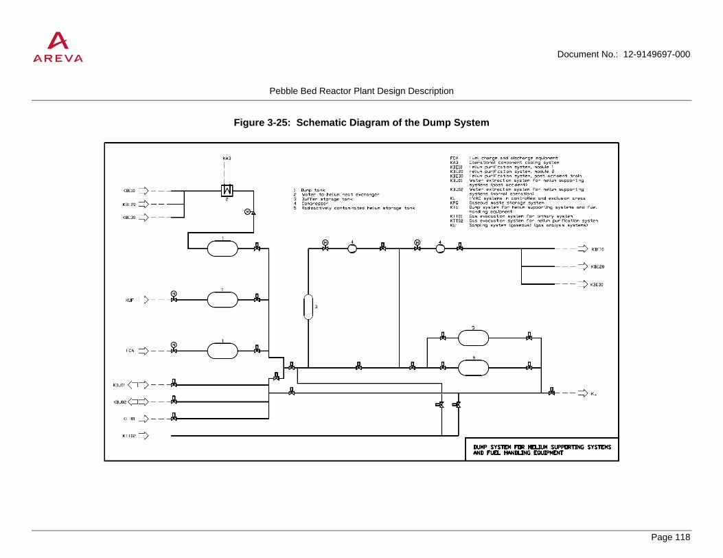
Document No.: 12-9149697-000
Pebble Bed Reactor Plant Design Description
Page 118
PROPRIETARY
Figure 3-25: Schematic Diagram of the Dump System

Document No.: 12-9149697-000
Pebble Bed Reactor Plant Design Description
Page 119
PROPRIETARY
Figure 3-26: Schematic Diagram of the Gas Evacuation System

Document No.: 12-9149697-000
Pebble Bed Reactor Plant Design Description
Page 120
PROPRIETARY
3.6 Fuel Handling and Storage System
The fuel handling and storage system (FHSS) comprises all the equipment that handles and stores the fuel elements during their lifetime: from the fresh fuel shipping casks through the core to the spent fuel storage/shipping casks or the failed fuel casks.
The moderator and absorber spheres, used during the first core load, are also circulated and stored by the FHSS.
Part of the FHSS is shared by the two reactors of the HTR-Module and part of it is independent, as shown on the high level scheme of Figure 3-27.
3.6.1 Fuel Handling System
The fuel handling system (FHS) continuously supplies the core with fuel. It fulfills the following functions:
• Charging new fuel elements into the fuel cycle
• Removal of fuel elements from the fuel discharge tube
• Recirculation of partially depleted fuel elements
• Separation of fuel element fragments and out-of-shape fuel elements
• Discharge of spent fuel elements and transfer to storage/shipping casks
• Loading of the first core
• Exceptional function: Transfer of the core inventory of an HTR-Module to storage/shipping casks and reloading the HTR-Module from these casks
The overwhelming majority of discharged fuel elements (approximately 5000 per day) has not yet reached final burn-up and is returned to the core (re-circulated). The daily requirement for new fuel elements is approximately 360 per full-load day per reactor.
Fuel elements are forwarded in horizontal and vertical tubes either by gravity or pneumatically mainly by primary coolant at primary system pressure (Figure 3-29).
Monitoring of fuel element transport and of buffer and lock line fill levels is performed with the aid of measurement and counting instruments whose signals actuate the working devices and valves of the forwarding system. These components include:
• Isolation valves at lock entry and exit to separate pressurized primary coolant-carrying portion (60 bar) from the atmospheric charge station (leakage monitored double seat valves and connection to the dump system for helium supporting Systems and fuel handling equipment)
• Rotary escapements for single-release of fuel elements into the following sub-systems (locks, buffer lines, forwarding lines)

Document No.: 12-9149697-000
Pebble Bed Reactor Plant Design Description
Page 121
PROPRIETARY
• Rotary pressure locks having the same function as the rotary escapements but with additional seals between regions at different carrier gas pressures
• Collecting points (passive components) for joining two converging tubes into one tube
• Diverting points to separate one tube into two diverging carrier lines
• Carrier gas inlets at the start and carrier gas outlets at the end of vertical and horizontal tubes
All fuel forwarding tubes and their valves and working parts are laid in shielded ducts and shafts and arranged in such a way that mechanical components can be replaced from accessible compartments.
Fuel elements are forwarded between the reactor and lock lines by gravity or pneumatically by primary coolant at approximately 60 bar and approximately 250°C.
Forwarding gas and braking gas are extracted from the region of the top reflector and fed to the suction side of the booster circulator. From the delivery side of the circulator the gas passes to the admission equipment at the start of the forwarding line. Arriving fuel elements are carried along by the flow of carrier gas from there. At the end of the carrier line, the gas flows back to the suction side of the circulator. Braking gas is returned to the primary system. Filters are provided in the carrier gas system to retain solids. Control, adjustment and switching of carrier gas flows is performed by motor-driven and manual adjustment, control and changeover valves; the carrier gas flow rates in the individual carrier gas lines are monitored by flow-meters.
A further pneumatic forwarding system with the necessary components such as circulators, filters, valves etc. is provided for forwarding spent and partially depleted fuel elements to the storage/shipping casks. This forwarding system operates with air or nitrogen at approximately 1 bar.
In exceptional cases, such as initial loading of the core or refueling of the core after emptying for repairs, pneumatic forwarding is performed with air or nitrogen at a pressure of approximately 1 bar with the reactor pressure vessel open. When filling the fuel discharge tube and the lower region of the core, the feed tube is extended to keep fuel element impact velocity within acceptable limits. The feed tube is accessible through an isolable opening in the top thermal shield and can be manipulated with the aid of suitable devices.
Systems of the fuel handling equipment are operational systems and connected to the normal auxiliary power supply (Section 3.11).
The fuel handling system equipment consists of two subsystems:
• The fuel feed equipment, which supplies the system with fresh fuel elements from the new fuel shipping casks.
• The fuel discharge equipment, which collects the fuel elements exiting the core and transfers them to the appropriate location (recirculation through the core or failed fuel cask or spent fuel storage/shipping casks).
3.6.1.1 Fuel Feed Equipment
The fuel feed equipment fulfills the following functions:

Document No.: 12-9149697-000
Pebble Bed Reactor Plant Design Description
Page 122
PROPRIETARY
• Removing of new fuel elements from shipping casks and transferring them to the charge lock
• Inserting the fuel elements into the fuel cycle through locks
• Forwarding the fuel elements to the core through the central fuel feed tube
• Forwarding partially depleted fuel elements back to the core after burn-up measurement
• Exceptional function: forwarding partially spent fuel elements from storage/shipping casks to the core
The following items are provided for these functions (Figure 3-29)
• The fuel charging unit for new fuel elements, shared by both modular units
• The charge lock for new fuel elements shared by both reactors, comprising process equipment of facilities such as purge air system and gas evacuation system for fuel handling equipment, dump system for helium supporting systems and fuel handling equipment and the helium supply and storage system through the helium purification system
• Systems for reloading the core with partially spent fuel elements from the storage/shipping casks after the core has been emptied
• Gravity fuel forwarding lines from the shared charge lock to each reactor's fuel discharge compartment
• Pneumatic elevation of new and partially depleted fuel elements from the fuel discharge compartment to the core
• One carrier gas system per modular unit
• Valves, working items, counters
New fuel elements are fed through a charging unit which is shared by both reactors but which is duplicated for availability reasons.
The new fuel shipping cask is flanged onto the charging unit and tipped. The fuel elements are removed one by one from the casks through a single-exit gate and travel under gravity to an inspection line in which they pass through a calibration device for a final check for possible oversize. If necessary, the fuel elements can be inspected visually.
The fuel elements pass along the connected buffer line under gravity and are then released one by one into the charging lock by a rotary escapement.
The processes described above take place in an air atmosphere and at ambient pressure.
When the lock line contains the required number of fuel elements (maximum capacity of approximately 360 per reactor, equivalent to daily requirement), the charge lock is placed under primary system atmosphere by such process actions as
• Operation of Isolation valves

Document No.: 12-9149697-000
Pebble Bed Reactor Plant Design Description
Page 123
PROPRIETARY
• Gas evacuation
• Filling of lock with purified helium up to equal pressure with the primary system
On completion of the locking process, the fuel elements are released one by one from the charge lock for forwarding to the core for one of the two reactors. On leaving the lock, the fuel elements run down gravity lines to the fuel discharge compartment beneath the reactor concerned. The fuel elements are then conveyed to the core through the connected pneumatic elevator, the forwarding tube and the central feed tube in the top reflector. The carrier gas is primary coolant at cold gas temperature.
A common nozzle which ends in a valve bank in the fuel discharge compartment is provided for the carrier tube/carrier gas return tube penetration through the reactor pressure vessel; this valve bank contains an isolation valve and a primary system isolation valve.
The fuel feed system is connected to the following systems:
• Dump system for helium supporting system and fuel handling equipment
• Fuel discharge equipment, equipment for reloading the core with partially depleted fuel elements from the storage/shipping casks.
• Purge air system, gas evacuation system for fuel handling equipment
• Helium supply and storage system, through the helium purification system
Design data for the fuel feed system are shown in Table 3-19.
Inspection and repair facilities during operation:
The actuators, including supply connections for valves and working parts, are located in accessible areas and can be inspected during reactor operation and repaired and replaced within limited periods of time without restricting reactor operation.
In addition, it is possible to replace valves and working parts, counters and the carrier gas circulator and its dust removal filter with the aid of suitable tools and fixtures (shielded where necessary).
This can be done while continuing power operation by isolating the fuel feed system from the primary system via double isolation valves. The fuel feed system can then be shut down, depressurized, and purged with air. It is not necessary to reduce or restrict operation if the repair periods are brief so that limits of operation in technical specifications are not exceeded.
3.6.1.2 Fuel Discharge Equipment
3.6.1.2.1 Overall Description
The fuel discharge system fulfills the following functions:
• Removal of fuel elements from the fuel discharge tube

Document No.: 12-9149697-000
Pebble Bed Reactor Plant Design Description
Page 124
PROPRIETARY
• Separation of failed and damaged fuel elements and transfer to the so-called failed fuel cask
• Fuel element forwarding to the pneumatic feed system (recirculation) or to the discharge buffer, as dictated by the results of burn-up measurement
• Discharge of spent fuel elements and forwarding to the storage/shipping casks
• Exceptional function: emptying of core into storage/shipping casks (without burn-up measurement or locking operations)
The following systems are provided for performing these actions (Figure 3-29):
• The fuel discharge equipment consisting of two fuel element single-exit gates with failed fuel separators and the fuel element buffer line (for each reactor)
• One failed fuel cask in the fuel discharge compartment of each reactor
• Connections to the fuel feed equipment
• The fuel forwarding system from the fuel discharge compartment of each reactor to the discharge lock (vertical: pneumatic, horizontal: under gravity)
• The fuel discharge lock shared by the two reactors in conjunction with the dump system for helium supporting systems and fuel handling equipment
• The pneumatic fuel elevator, including the carrier gas system from the fuel discharge lock shared by the two reactors to the fuel filling station
• The fuel filling station with process equipment for filling the storage/shipping casks with spent fuel and, in the special case of emptying the core, with partially depleted fuel elements
The fuel elements are conveyed from the core through the fuel discharge tube to the fuel discharge equipment. The fuel discharge tube is closed by two single-exit gates, each of which is connected to a failed fuel separator. Only one single-exit gate/failed fuel separator unit is in operation at any given time. The single-exit gate extracts the fuel elements from the fuel discharge tube. The fuel elements pass directly to the failed fuel separator from the single-exit gate. The failed fuel separator is a chute of trapezoidal cross-section with a helical path. Since the chute is open at the bottom, damaged fuel elements and fuel element fragments fall out of the chute into the failed fuel cask.
The failed fuel cask is a pressure vessel located in mobile shielding and shipping casks. The fill level is monitored by measuring instruments. The failed fuel cask is connected to the primary system by two connecting lines with one primary system isolation valve each.
Intact fuel elements pass out of the fuel discharge equipment, through a connected valve assembly consisting of an isolation valve and a primary system isolation valve, then through a buffer line to an escapement which releases each fuel element one by one for burn-up measurement. If final burn-up has not yet been reached, the fuel elements are returned to the core through the feed equipment.

Document No.: 12-9149697-000
Pebble Bed Reactor Plant Design Description
Page 125
PROPRIETARY
Spent fuel elements are collected in a buffer line provided for this purpose and then conveyed to a discharge lock shared by both reactors.
All operations described above take place under primary system atmosphere at 60 bar and system temperature of 250°C maximum. When the lock line contains the required number of fuel elements (max. 360 = daily requirement) the discharge lock is adjusted to the conditions of the subsequent forwarding system (max. 1.5 bar, about room temperature) by such process actions such as
• Operation of isolation valves
• Depressurization
• Filling with air or nitrogen
The fuel elements are released one by one from the discharge lock and are forwarded pneumatically by air or nitrogen to the loading positions of the two storage/shipping casks. They are dropped in a loose pile.
The fill level is monitored by counters. When a storage/shipping cask is full, changeover to the loading system of the second cask is effected, the fill port (approximately 65 mm) is closed, the filling bank uncoupled and the cask is conditioned for removal.
The fuel discharge equipment is connected to the following systems
• Dump system for helium supporting systems and fuel handling equipment
• Gas evacuation system for fuel handling equipment
• Helium supply and storage system, through the helium purification system
• Fuel feed equipment, storage/shipping casks
Design data for the fuel discharge system are shown in Table 3-20.
Inspection and repair facilities are equivalent to those described in Section 3.6.1.1.
3.6.1.2.2 Burn-up Measurement Unit
In a multiple-recycle HTR-Module, measurement of fuel element burn-up is needed to decide whether a particular fuel element can be returned to the core or should be placed into storage for disposal. The burn-up measurement unit provided to determine the burn-up of each fuel element is a computer-controlled operational instrumentation system. Each reactor is provided with a separate fuel element measurement unit. The degree of burn-up is determined by gamma spectroscopic evaluation of the 662 keV gamma line of the isotope Cs-137. Since this fission product has a half-life of 30.1 years the intensity of this gamma line is proportional to burn-up. The fuel element reaches its target burn-up of approximately 80,000 MWd/MgU, which is equivalent to a Cs-137 activity of approximately 7.7 x 10¹⁰ Bq, on average after the 15th cycle through the core and is then discarded.
After leaving the core area the time taken for a fuel element to pass through the fuel discharge tube to the rotary pressure lock and from there to the fuel element burn-up measuring unit is approximately 55 hours. During this period the total fission product activity of the fuel element falls by a factor of three approximately, thereby

Document No.: 12-9149697-000
Pebble Bed Reactor Plant Design Description
Page 126
PROPRIETARY
improving the signal (Cs137) to background ratio. The associated interference lines of the nuclides I132 and Nb97 are also reduced at the same time.
The components of the burn-up measuring unit are located in the compartment below the fuel element discharge. The electronic equipment (main amplifier, high voltage supply, etc.) connected to the detector and preamplifier is located in a separate transducer compartment. A nitrogen storage tank is also provided for cooling of the detector.
The gamma spectrum of the fuel element is measured by the burn-up measuring unit. Part of the radiation from the fuel element is focused by a collimator on a nitrogen-cooled high-resolution HP germanium semiconductor detector with an energy resolution (half-amplitude width) of about 3 keV. The events registered by the semiconductor detector are transmitted by the associated electronic amplifier circuit to a multi-channel analyzer to produce the pulse amplitude spectrum (distribution and intensity of gamma energy) of the fission products contained in the fuel element.
The multi-channel analyzer passes a section of the pulse amplitude spectrum (range approximately 600 to 750 keV) to a microcomputer which determines the content of the Cs137 line at 662 keV. The gamma lines of other nuclides – I132 (668 keV) and Nb97 (658 keV) – associated with Cs137 (gamma energy 662 keV) are taken into account in the evaluation by expanding the spectrum in the area of the Cs137 line. The Cs137 line, its contents cleaned of background and adjacent gamma lines, is very nearly proportional to the fuel element burn-up and forms the basis for the decision (control signal) whether the fuel element is returned to the core or discarded.
With a time of measurement limited to about 10 seconds, the instrumentation hardware can be expected to provide an accuracy of ±5%. Fuel elements with a burn-up higher than 88,000 MWd/MgU are discarded with a probability of 98%.
From the pulse amplitude spectrum it is also possible to identify the moderator and absorber balls which are mixed with the fuel elements in the first core load and must be gradually withdrawn from the core in the course of the running-in phase.
3.6.2 New Fuel Storage
Double-walled series-produced 200 L hooped drums (new fuel shipping casks) with enough capacity for about 1000 fuel elements per cask are used. The gap between the outer and inner walls of the drums is filled with fine-grained Ferro boron with a boron content of approximately 18% by weight. The casks can thus be stored in any number and arrangement. No complex technical or administrative measures need to be taken with respect to criticality. The fuel elements are stored in the tightly closed casks in an air atmosphere in the reactor auxiliary building.
The new fuel storage holds a stock of shipping casks and is designed to contain one-year's fuel requirements, i.e. approximately 200,000 fuel elements, equivalent to about 200 casks.
Suitable hoists and trucks are provided for handling and transporting the casks within the new fuel storage area. A storage buffer is provided in the fuel charging station because of the physical separation of the new fuel storage from the fuel charging station in the reactor building. Trucks are used to transport the casks to the reactor building and then to the storage buffer, which is in one compartment within the fuel charging station. The casks are stacked as in the new fuel storage. The storage buffer is designed for a minimum of 10 casks.

Document No.: 12-9149697-000
Pebble Bed Reactor Plant Design Description
Page 127
PROPRIETARY
3.6.3 Spent Fuel Storage
Each full power day, 360 spent fuel elements are brought to the spent fuel store for each reactor. Therefore, approximately 263,000 elements per full power year are to be stored.
Spent fuel elements are emptied from the filling station into storage/shipping casks in a loose pile.
The cask is ready for removal after it has been filled and the technical operations have been completed (see Section 3.6.1.2) and after the cover system has been fully assembled and a leakage test and contamination check have been carried out.
The cask is transported vertically from the fuel filling station on a rail-mounted truck into the area served by the reactor building crane. It is then carried through the erection shaft to the transport floor by the reactor building crane and loaded onto a truck. The cask is placed in temporary storage in the spent fuel store provided on the power plant site (see Section 3.14.6). Section 3.14.6 addresses spent fuel storage capacity.
3.6.3.1 Storage/Shipping Casks
The storage/shipping cask that has been developed for the PWR fuel elements is taken over for the HTR-Module fuel elements regarding transport and interim storage. It consists of nodular cast iron (material GGG 40.3) and has the following dimensions:
• length (overall dimensions, including shock absorber) approximately 7000 mm
• outside diameter (overall dimension) approximately 2500 mm
The capacity amounts to approximately 30,000 fuel elements.
Sealing and shielding of the filling opening is performed by a double cover system that is made out of stainless steel casting and bolted to the base body using metallic gaskets.
An internal lining which consists of stainless steel and boron steel is designated for the uptake of the fuel elements.
The interstice in the double cover system will be monitored regarding leak-tightness control via outwardly leading terminals.
Considering the capacity of the storage/shipping cask, the filling time is about 42 EFPD out of the two reactors.
The decay heat generation from the fuel elements produces a maximum of approximately 19 kW in the cask immediately after loading. The temperature that results for the upright standing cask in freely circulating air immediately after filling and closure is approximately 80°C.
By utilizing the slight decay power density or the low specific activity inventory, the casks can be optimized to increase their capacity up to 45,000 fuel elements, depending on the requirements for temperatures and dose rates.
The casks are designed and fabricated under strict quality control to assure that the following functional requirements are met:
• Shielding of fuel element radiation

Document No.: 12-9149697-000
Pebble Bed Reactor Plant Design Description
Page 128
PROPRIETARY
• Retention of fission or activation products released from the fuel elements (Kr85, H3)
• Removal of decay heat without unacceptably high temperature build-up
• Maintenance of integrity during events such as dropping, collision, fire, earthquake, explosion, airplane crash, wreckage load etc.
3.6.3.2 Core Emptying and Reloading
The HTR-Module power plant is designed in such a way that the core does not need to be emptied. For reasons of availability, however, dedicated storage / shipping casks are available so that the entire contents of the core can be emptied in case of extraordinary repairs.
In principle, the storage/shipping casks are loaded and handled when emptying the core in the same manner as for normal operational disposal. However, before the casks are loaded, they are fitted with a special cover in the shipping cask handling compartment (elevation -12.7 m) and a single-exit disc is integrated into this special cover for later emptying of the cask.
During emptying the core the shipping casks are identified with numbers for assuring the correct order for later reloading of the core.
After loading, the casks are sealed with an additional secondary cover and stored in the spent fuel store on the power plant site pending reloading of the core (see Section 3.14.6). Dose rates and surface temperatures in this case are similar to those for temporary storage of spent fuel elements.
When emptying the casks for core refueling, the secondary cover must first be replaced with a special cover in the handling compartment mentioned above. This special cover contains the drive mechanism for the single-exit gate, the extraction device for the plug in the discharge opening and a fuel discharge duct. The casks are emptied at elevation ±0.0 m.
This is done by tipping the casks on the transport cars using special equipment and the hall crane, thus emptying them by gravity. The fuel discharge duct of the special cover is then connected to a shielded feed line of the fuel feed equipment provided for this operation. After having left the cask, the fuel elements are first conveyed to a failed fuel separator before they reach the operational carrier system under gravity.
The possibility of intervening in the cask emptying in the event of accident has been provided for.
3.6.3.3 Failed Fuel Storage
Fuel is discharged into the separate failed fuel casks below each reactor and below the refueling equipment by way of a failed fuel separator which removes fuel element fragments or fuel elements with geometric flaws. The failed fuel is dumped in a loose pile.
This failed fuel cask has a capacity of approximately 2000 fuel elements. Based on the failed fuel element rate of the AVR (about 5x10⁻⁵ failed fuel elements per circulated fuel element), this cask will be filled within about 20 full-load years. After filling, the failed fuel cask will be transported to the fuel element interim storage in a shielded cask, which fulfills the requirements for a shipping and storage cask (see Section 3.14.6).

Document No.: 12-9149697-000
Pebble Bed Reactor Plant Design Description
Page 129
PROPRIETARY
3.6.4 Handling of Components for Maintenance and Repair of Fuel Feed and Discharge Equipment
3.6.4.1 Valves and Mechanical Components
The various valves under primary system pressure, such as isolation and primary system isolation valves, escapements, rotary pressure locks, collecting points, diverting points, etc., are arranged in valve banks. Fuel element forwarding tubes and carrier gas supply tubes are connected to these banks. The pneumatic actuators for these valves are located outside the primary system.
Routine inspections, maintenance operations and minor repairs are carried out during reactor operation with the fuel feed and discharge equipment shut down. For these operations, the fuel feed and discharge equipment is cut off from the primary system by the isolation valves at the reactor pressure vessel, then depressurized, evacuated and purged. Preventive replacement of wear parts such as antifriction bearings, dynamic gaskets etc. in frequently cycled items such as rotary escapements, rotary pressure locks, lock valves etc. is carried out during planned outages.
The valve banks are designed such that a dose rate of 0.5 mSv/h (50 mrem/h) is not exceeded during reactor operation.
Drive units, rotary escapements, rotary pressure locks, lock valves etc. are disassembled, reassembled and removed using a system of handling devices equipped with suitable handling tools.
Disassembly and reassembly of contaminated internals is performed with the aid of shielded handling devices mounted on suitable carriers.
The following principal requirements are placed on the systems concerned:
• Limitation of radiation exposure in work areas
• Prevention of contamination in the vicinity of the equipment location
• Pulling and gripping tools adapted to the internals concerned to minimize working time
• Ability to be decontaminated
After decontamination, the valve bank internals are further treated in the hot workshop. The equipment handling flask containing the disassembled items is transported by means of trucks and/or lifting gear.
3.6.4.2 Handling of Failed Fuel Casks
The failed fuel cask for the fuel discharge equipment is a pressure vessel designed for primary system pressure.
The cask can be changed with the reactor shut down and the primary system depressurized.
The failed fuel casks are enclosed by a mobile shielding cask which meets the requirements placed on the storage/shipping casks.
When the failed fuel cask has been filled to full capacity, it is changed together with its shielding cask. For this purpose, the complete cover system is put on and subsequently a leak test and a contamination check are carried

Document No.: 12-9149697-000
Pebble Bed Reactor Plant Design Description
Page 130
PROPRIETARY
out. The cask is transported upright out of the fuel discharge compartment into the area served by the reactor building crane. It is further transported by the reactor building crane through the erection shaft to the transport floor, where the cask is transferred to a transport truck for removal.
After the core has been reloaded, the separate failed fuel cask beneath the refueling equipment is disposed of.
3.6.4.3 Failed Fuel Separator
After the fuel elements have passed through the core, they travel down the cast steel, internally shielded portion of the fuel discharge tube to the forged block attached to the reactor pressure vessel. This block contains two single-exit gates with a failed fuel separator and also provides shielding against radiation of the stack of fuel elements in the fuel discharge tube.
Inspections, maintenance operations and repairs to the failed fuel separator components outside the primary gas envelope can be carried out during reactor operation.
For inspections and replacement of wear parts (bearings, seals) of internals of the forged block, which is part of the primary gas envelope, the failed fuel separator is removed at the required maintenance intervals with the reactor shut down and the primary system depressurized. This also applies also to unforeseen repairs.
The design of the single-exit gate makes removal unnecessary; however, it is possible in principle after emptying the core.
The forged block containing the failed fuel separators is designed, like the valve banks, to be self-shielding.
The failed fuel separator internals are disassembled, reassembled and transported with a shielded equipment handling flask equipped with the necessary handling tools. A gate valve is flanged to the body of the flask as a gastight and radiation-reducing seal. The equipment handling flask is connected up via a separately flanged, shielding gate valve on the forged block. A rail-mounted truck which allows radial, horizontal and vertical movement serves to carry the equipment handling flask on its side and the gate valve.
After the failed fuel separator has been decontaminated, it is further treated in the hot workshop. The loaded equipment handling flask is transported by trucks and/or lifting gear.

Document No.: 12-9149697-000
Pebble Bed Reactor Plant Design Description
Page 131
PROPRIETARY
Table 3-19: Design Data of Fuel Feed Equipment
Item Value Total fuel elements fed through feed tube per equivalent full-power day (EFPD) and per modular unit Of these, partially depleted (re-circulated) per EFPD
approx. 5360 approx. 5000
New fuel elements fed per EFPD and per modular unit approx. 360 Average travel time per fuel element through forwarding block approx. 16 s Change time for new fuel tanks – for one charging position – for two charging positions
approx. 33 h approx. 67 h
Charging lock fuel element capacity approx. 360 Number of feed tubes per modular unit 1 Operating pressure ahead of charging lock Design pressure ahead of charging lock
max. 1.5 bar 2 bar
Operating pressure after charging lock Design pressure after charging lock
60 bar 70 bar
Operating temperature ahead of charging lock Design temperature ahead of charging lock
20°C 50°C
Operating temperature after charging lock Design temperature after charging lock
250°C 350°C

Document No.: 12-9149697-000
Pebble Bed Reactor Plant Design Description
Page 132
PROPRIETARY
Table 3-20: Design Data of Fuel Discharge Equipment
Item Value Total fuel elements fed through feed tube per equivalent full-power day (EFPD) and per modular unit Of these, partially depleted (re-circulated) per EFPD
approx. 5360 approx. 5000
Spent fuel elements discharged per EFPD and per modular unit approx. 360 Average travel time per fuel element approx. 16 s Anticipated failed fuel at discharge tube per modular unit and per year approx. 90 Fuel element capacity of failed fuel casks approx. 2000 Filling time of failed fuel cask approx. 20 years Fuel element capacity of discharge lock approx. 360 Fuel element capacity of spent fuel storage/shipping casks approx. 30000
or approx. 45000 Number of spent fuel storage/shipping casks in reactor building 2 Operating pressure ahead of discharge lock Design pressure ahead of discharge lock
60 bar 70 bar
Operating pressure after discharge lock Design pressure after discharge lock
max. 1.5 bar 2 bar
Operating temperature ahead of discharge lock Design temperature ahead of charging lock
250°C 350°C
Operating temperature after discharge lock Design temperature after charging lock
20°C 50°C

Document No.: 12-9149697-000
Pebble Bed Reactor Plant Design Description
Page 133
PROPRIETARY
Figure 3-27: High Level Scheme of Fuel Handling and Storage System

Document No.: 12-9149697-000
Pebble Bed Reactor Plant Design Description
Page 134
PROPRIETARY
Figure 3-28: Burn-up Measurement Unit

Document No.: 12-9149697-000
Pebble Bed Reactor Plant Design Description
Page 135
PROPRIETARY
Figure 3-29: Fuel Handling Equipment

Document No.: 12-9149697-000
Pebble Bed Reactor Plant Design Description
Page 136
PROPRIETARY
3.7 Reactor Auxiliary Systems
3.7.1 Component Handling Equipment
Equipment is provided for disassembling, reassembling, and transporting irradiated and contaminated plant items. Shielding of the equipment is designed as appropriate to the level of radiation anticipated for the item being handled.
Set down and storage facilities, decontamination equipment, and workshops are provided in the reactor building and the reactor auxiliary building for further treatment and storage of irradiated and contaminated plant items and/or components and handling equipment.
The principal components which would require handling are:
• Reflector rod
o Drive mechanism Contaminated
o Reflector rod Activated
• Small ball shutdown unit
o Storage vessel Contaminated
o Shielding plug Activated
• Neutron source Activated
• Shielding plug Activated
• Fuel feed tube (elbow) Activated
• Circulator unit Contaminated
• Failed fuel separator Contaminated
It is expected that activated components will be disassembled and reassembled with shielded, gastight equipment handling vessels, and contaminated components with thin walled, gastight equipment handling vessels.
The main requirements for the equipment handling vessels and their closures are the following:
• Limitation of radiation exposure in work areas
• Prevention of contamination of the work area
• Prevention of unacceptable ingress of air into the primary system and unacceptable leakage of primary coolant
• Adaptation of pulling and gripping tools to the components being handled
Document No.: 12-9149697-000
Pebble Bed Reactor Plant Design Description
Page 137
PROPRIETARY
• Decontaminability
The equipment handling vessels are transported within the reactor hall by the reactor building crane. The sequence of operations is controlled and monitored using mechanical, electrical, and optical devices on the flasks and lifting gear. After disassembly and reassembly, the equipment handling vessels are purged and, if necessary, decontaminated.
3.7.2 Sampling System (Gas Analysis System)
Contaminants in the primary helium system, in auxiliary systems, and at various locations in the helium purification system are monitored by gas analysis for early detection of disturbances.
High-sensitivity humidity measurement is required of the gas analysis equipment. Leakage is monitored to detect steam generator tube breaks. Detected leakage generates an input signal for the reactor protection system.
Contamination of the primary system is caused by water, air, or oil leakage. The ingress rate of these materials is monitored by measuring the concentration of chemical contaminants.
Fuel element performance and other variables are monitored by measuring radioactive contamination.
3.7.2.1 System Description
The measuring locations, measuring instruments and analyzers, and the specific contaminant constituents measured are listed in Table 3-21. Measurements are described below.
The individual gas sampling lines from the monitored system components to the individual measuring instruments/analyzers are routed separately to minimize delayed readings due to adsorption and desorption and sample travel time. Samples are taken with sampling collectors (e.g. gas sampling cartridges) for contaminants requiring an increase in concentration prior to analysis (e.g. C-14, Kr-85, tritium).
In general, all measuring instruments operate at normal pressure. Only the hygrometers require increased pressure to improve accuracy and precision.
The sampled gas from all instruments/analyzers is collected in a dump tank to prevent helium losses and reduce radioactivity releases. Only small quantities of gas from intermittent gas chromatography are released directly into the exhaust air.
3.7.2.2 Measuring Instruments and Analyzers
For availability reasons, two gas chromatographs, two hygrometers and two oxygen meters are provided. Redundancy in infrared devices is provided in that concentrations of CO and CO2 are proportional to each other as described by Boudouard equilibrium.
The gamma spectrometer provides automatic determination of the individual specific activities.
For tritium analysis, an increase in concentration and simultaneous separation from other active fractions are necessary. The sampled gas is passed through an oven with a copper oxide bed in which the tritium-containing components CH3T and HT are converted to HTO. This HTO is trapped in a water seal together with the originally present HTO and then measured with a liquid scintillation spectrometer.
Document No.: 12-9149697-000
Pebble Bed Reactor Plant Design Description
Page 138
PROPRIETARY
The sampled gas for Kr-85 measurement must also be increased in concentration prior to analysis. This is done using a small pump in a compressed gas bottle. The sample must cool off for a few days before measurement to allow decay of most of the short-lived noble gas isotopes.
C-14 is present as 14CO and 14CO2 in the helium. 14CO is converted together with inactive CO to 14CO2 and inactive CO2 in a copper oxide bed. Since 14C is only a weak beta emitter, it must be chemically separated for beta spectroscopy. This is done by precipitating the CO2 as barium carbonate. Beta activity is measured in the washed BaCO3 precipitate.
3.7.2.3 Measurements
The infrared analyzers, hygrometers and the beta detectors operate continuously. The gas chromatographs operate intermittently. According to operational experience at the AVR and at Peach Bottom, daily measurement is sufficient for monitoring the primary system and the helium purification system. Tritium measurement, gamma spectroscopy, and Kr-85 measurement is performed at longer intervals.
Significant amounts of water or air are detected by the hygrometers and the infrared devices. They detect the chemical reaction products due to water in-leakage, CO and CO2.
Slight in-leakage of water of a few grams per hour is not detected reliably by the hygrometers alone because water is rapidly converted by chemical reactions in the core. However, small leakages are detected by the infrared analyzer which detects the reaction product CO. To discern whether a slight increase in CO is due to water or air in-leakage, an additional measurement is carried out with by a gas chromatograph. If the concentration of H2 has increased as well, then water in-leakage is the cause. This analysis and monitoring approach is possible because plant operation is not endangered by slight air or water in-leakages. Sufficient periods of time are available before it would be necessary to take corrective action.
3.7.3 Core Barrel Leak Testing System
Before opening the reactor pressure vessel for maintenance operations, it is necessary to check that the core barrel, the core barrel support, and the top thermal shield with its flanged superstructures are sufficiently leak-tight by conducting an integral leak test.
3.7.3.1 System Description
The leak testing system for the core barrel consists of piping and a vacuum gauge. The vacuum gauge is sufficient for low vacuum measurements.
An isolation valve of the gas evacuation system for the primary system cuts the leak testing system off from the gas evacuation system for the primary system during leak testing.
During reactor operation, the leak testing system is not connected to the primary system, but rather isolated by a blanking flange (Figure 3-26) since the system has no functions to fulfill during reactor operation; consequently, it is not subject to the design requirements of the primary system (pressure, temperature).
3.7.3.2 Leak Test Performance
The leak testing system is connected up to the nozzles provided in the pressure equalizing system (closed by a blanking flange during reactor operation) after the primary system has been depressurized and the isolation valve

Document No.: 12-9149697-000
Pebble Bed Reactor Plant Design Description
Page 139
PROPRIETARY
in the pressure equalizing system closed. The area above the core barrel support is evacuated to approximately 10 mbar. The gas evacuation system is then cut off from the leak testing system by the isolation valve. The leak test is carried out using the pressure rise method. Leak-tightness is sufficient if the pressure rise does not exceed 5 mbar/h.
3.7.4 Radioactive Waste Processing Systems
3.7.4.1 Liquid Waste System
The system for storing and processing radioactive liquid waste collects and treats radioactive effluents from the controlled area. The liquid waste is not pumped out of the monitoring tank (released) until gamma activity measurement has shown that the radionuclide concentration of the liquid in the monitoring tank is no greater than 1.85x10⁷ Bq/m3 (5x10⁻⁴ Ci/m3) Cs-137 equivalent. (Refer to Table 3-22 and Figure 3-30.)
Storage of radioactive liquid waste
Liquid waste is collected separately according to its chemical condition and activity as follows:
• Group I: Active liquid waste
o Sump and leak-off liquid waste
o Liquid waste from hot laboratory
o Liquid waste from decontamination compartment
o Decanted liquid from the concentrates tank in the liquid waste system
o Liquid waste from the liquid waste system evaporator
o Liquid waste from the concentrates processing system
• Group II: Low-level to inactive liquid waste
o Liquid waste from laundry
o Liquid waste from showers and washrooms
Liquid waste from showers and washrooms is normally inactive and passes directly to the monitoring tanks. If its activity changes in the course of operation, it can be passed to the Group II liquid waste collecting tanks.
Liquid waste collecting tanks
Liquid waste is collected in separate liquid waste collecting tanks for each of the two groups. Two tanks are provided per group. To determine activity and chemical composition, the contents of the tank are mixed and a sample is taken.
Solid sediments are collected in the cones of the tanks and are pumped intermittently to the concentrate tank.
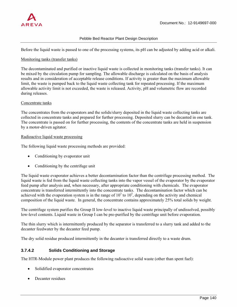
Document No.: 12-9149697-000
Pebble Bed Reactor Plant Design Description
Page 140
PROPRIETARY
Before the liquid waste is passed to one of the processing systems, its pH can be adjusted by adding acid or alkali.
Monitoring tanks (transfer tanks)
The decontaminated and purified or inactive liquid waste is collected in monitoring tanks (transfer tanks). It can be mixed by the circulation pump for sampling. The allowable discharge is calculated on the basis of analysis results and in consideration of acceptable release conditions. If activity is greater than the maximum allowable limit, the waste is pumped back to the liquid waste collecting tank for repeated processing. If the maximum allowable activity limit is not exceeded, the waste is released. Activity, pH and volumetric flow are recorded during releases.
Concentrate tanks
The concentrates from the evaporators and the solids/slurry deposited in the liquid waste collecting tanks are collected in concentrate tanks and prepared for further processing. Deposited slurry can be decanted in one tank. The concentrate is passed on for further processing, the contents of the concentrate tanks are held in suspension by a motor-driven agitator.
Radioactive liquid waste processing
The following liquid waste processing methods are provided:
• Conditioning by evaporator unit
• Conditioning by the centrifuge unit
The liquid waste evaporator achieves a better decontamination factor than the centrifuge processing method. The liquid waste is fed from the liquid waste collecting tanks into the vapor vessel of the evaporator by the evaporator feed pump after analysis and, when necessary, after appropriate conditioning with chemicals. The evaporator concentrate is transferred intermittently into the concentrate tanks. The decontamination factor which can be achieved with the evaporation system is in the range of 103 to 105, depending on the activity and chemical composition of the liquid waste. In general, the concentrate contains approximately 25% total solids by weight.
The centrifuge system purifies the Group II low-level to inactive liquid waste principally of undissolved, possibly low-level contents. Liquid waste in Group I can be pre-purified by the centrifuge unit before evaporation.
The thin slurry which is intermittently produced by the separator is transferred to a slurry tank and added to the decanter feedwater by the decanter feed pump.
The dry solid residue produced intermittently in the decanter is transferred directly to a waste drum.
3.7.4.2 Solids Conditioning and Storage
The HTR-Module power plant produces the following radioactive solid waste (other than spent fuel):
• Solidified evaporator concentrates
• Decanter residues

Document No.: 12-9149697-000
Pebble Bed Reactor Plant Design Description
Page 141
PROPRIETARY
• Solid operational waste
• Filters from the HVAC systems and other controlled area systems
• Wear parts of nuclear components
• Filter drums from the decontamination facilities
The waste is collected in containers or 200 L hooped drums and stored in the power plant pending conditioning.
Solids Conditioning
The solid radioactive waste generated in the power plant is conditioned to meet the storage requirements.
Evaporator concentrates are solidified in 200 L hooped drums.
Decanter residues are filled into 200 L hooped drums and are stored pending transfer to an offsite incineration plant. After offsite conditioning the decanter residue ashes, which are immobilized in cement, are returned to the plant in 200 L hooped drums.
Solid operational waste is collected in containers and sorted into combustible and non combustible waste. The solid operational waste is then shipped to an offsite conditioning plant and, after conditioning, is returned to the plant in 200 L hooped drums in the form of waste or ash which has been immobilized in cement.
The filters from the HVAC systems of the controlled area are sealed in plastic sheet and collected in containers. After offsite conditioning, the filter ashes, which have been immobilized in cement, are returned to the plant in 200 L hooped drums.
Wear parts from nuclear systems are filled into 200 L hooped drums and are cast in cement lime in a mobile processing unit.
Filter drums from decontamination systems are dewatered and cast in cement lime in a mobile processing facility.
Evaporator condensate liquids can be treated in mobile treatment units in the power plant, or the waste can be transported in liquid form to an offsite conditioning plant.
Solids Storage
After conditioning of the solid waste, about 90 hooped drums (200 L each) are expected on average per year. These drums are temporarily stored in the drum storage area in the reactor auxiliary building. The capacity of the drum storage area is approximately 200 assuming that 200 L hooped drums are used. Radiological protection considerations are taken into account in the design of the drum storage. This also applies to handling equipment. The drums are transferred to an off-site ultimate repository.
3.7.4.3 Decontamination Equipment
To minimize the dose to workers, mobile decontamination equipment is used for decontaminating activity-carrying items such as heat exchangers, tanks, and vessels in the reactor auxiliary building before in-service inspection or repairs. The system must be capable of removing contaminants from surfaces without causing unacceptable damage to the base material. A high decontamination factor must be achieved using a minimum

Document No.: 12-9149697-000
Pebble Bed Reactor Plant Design Description
Page 142
PROPRIETARY
amount of chemical decontamination agents. The equipment is installed on two mobile trucks - a decontamination truck and a filter truck – and consists of a chemical mixing and circulating tank with decontamination pump, agitator, discharge pump, filter and heater. Various spray heads in different sizes (according to vessel type with suitable fixtures for inserting the heads) allow for spraying of the interior walls of the item. Various cleaning processes can be implemented using this unit as appropriate for the extent and type of contamination.
Small contaminated machine components - valves, tools, rubber gloves, etc. - are decontaminated in the decontamination compartment of the reactor auxiliary building using acid, lye, and demineralized water in wash tubs. For larger parts requiring decontamination, a decontamination box is set up in which the items can be treated with water, wet steam, or acid. Items in which slight metal thinning is acceptable can be cleansed using a jetting unit. The decontamination equipment is fitted with air extractors.
3.7.4.4 Water Extraction System for Helium Supporting Systems
The water extraction system performs the following functions:
• During water in-leakage accident, the system removes and stores condensate collected in the post-accident water separator of the third train of the helium purification system.
• During normal operation, the system removes and stores the condensate which is collected during regeneration of the trains of the helium purification system.
3.7.4.4.1 System Description
Water extraction system for helium supporting systems (post-accident)
This subsystem receives the water and condensate collected in the post-accident water separator after a water in-leakage accident. The dump system for helium supporting systems and fuel handling equipment adjusts the gas pressure downstream of the float traps to approximately atmospheric pressure. The condensate is accommodated in storage tanks for condensate collected during accidents (volume: approximately 2.5 m3).
The condensate collected during commissioning is also discharged into this subsystem through the post-accident water separator in the post-accident train of the helium purification system.
Water extraction system for helium supporting system (normal operation)
This subsystem receives condensate collected during operation; in essence, this is tritium-laden liquids from regeneration of the trains of the helium purification system. The dump system for helium supporting systems and fuel handling equipment adjusts the gas pressure after the float traps to approximately atmospheric pressure.
The condensate is first collected in a holding tank in the reactor auxiliary building. From the holding tank, the condensates are conveyed to a storage tank for condensate collected during operation. The tank is designed for earthquakes and is located in the reactor building (volume: approximately 2.5 m3).
Approximately 560 L of tritium-laden liquid waste is expected to be produced by regeneration over a reactor service life of 32 equivalent full-power years.

Document No.: 12-9149697-000
Pebble Bed Reactor Plant Design Description
Page 143
PROPRIETARY
3.7.5 Nuclear Buildings Drainage System
The Nuclear Buildings Drainage System collects liquid waste from leaks and system draining in the controlled area (reactor building, reactor building annex, reactor auxiliary building), and transfers it to the radioactive liquid waste system.
3.7.5.1 System Description and Operation
The liquid waste flows through floor drains in the compartments to building drainage sumps in the various sections of the structures. The pipes connecting the floor drains to the building drainage sumps are laid at downward gradients. The floor drains in compartments at the various subatmospheric pressure levels required by the design requirements for the HVAC systems have constantly filled loop seals (hydraulic seals).
The floor drains are connected to the central building drainage sumps. The building drainage sumps are located at the lowermost levels of the building sections.
Depending on structure layout, there are:
• Holding sumps for building drainage
• Pumped sumps for building drainage
Liquid waste is conveyed from the pumped sumps, which are integrated into the plumbing networks of the building drainage system, through discharge lines to the liquid waste system in the reactor auxiliary building.

Document No.: 12-9149697-000
Pebble Bed Reactor Plant Design Description
Page 144
PROPRIETARY
Table 3-21: Gas Measurement Locations and Instruments and Analyzers
Measurement Location Instrument/Analyzer Contaminants
Primary systems (letdown line of the helium purification system)
Hygrometer H2O
Infrared analyzer CO, CO2
Gas chromatograph H2, CO, CO2, N2, CH4, Ar, O2
Beta detector Total noble gas activity
Gamma spectrometer Kr and Xe isotopes
Sampling Tritium, Kr85, C14
Helium purification system (after CuO bed) O2 monitor O2
After helium purification system (ahead of branch to purified gas store)
Gas chromatograph
H2, CO, CO2, N2, CH4, Ar, O2
Beta detector Total noble gas activity
Gamma spectrometer Kr and Xe isotopes
Sampling Kr-85
Dump system of helium supporting systems and fuel handling equipment
Gas chromatograph
H2, CO, CO2, N2, CH4, Ar, O2
Gamma spectrometer Kr and Xe isotopes
Storage tank for radioactively contaminated helium
Gas chromatograph
H2, CO, CO2, N2, CH4, Ar, O2
Beta detector Total noble gas activity
Sampling Tritium, Kr-85, C-14

Document No.: 12-9149697-000
Pebble Bed Reactor Plant Design Description
Page 145
PROPRIETARY
Table 3-22: Radioactive Liquid Waste Processing and Storage System
Parameter Value Average weekly liquid waste production Group I Approx. 27 m3 Group II Approx. 70 m3 Processing capacity Evaporator 0.28 kg/s Centrifuge unit 0.7 kg/s Storage capacity Liquid waste collecting tanks 4 x 20 m3 = 80 m3 Monitoring tanks 3 x 20 m3 = 60 m3 Concentrate tanks 2 x 10 m3 = 20 m3

Document No.: 12-9149697-000
Pebble Bed Reactor Plant Design Description
Page 146
PROPRIETARY
Figure 3-30: Liquid Waste Processing and Storage System Schematic Diagram

Document No.: 12-9149697-000
Pebble Bed Reactor Plant Design Description
Page 147
PROPRIETARY
3.8 Energy Conversion Plant
The energy conversion plant (ECP) receives steam from the steam generators for electricity generation or process applications, and returns feedwater to the steam generator. The boundary between the nuclear heat source and the ECP is on the ECP side of the second series steam generator isolation valve in each line.
3.8.1 Water/Steam Cycle
The steam/power conversion system is designed for maximum operational reliability, availability and cost-effectiveness with the simplest possible and manageable configuration.
To satisfy the availability requirements with respect to power and process steam generation, the steam/power conversion system consists of two identical, suitably interconnected half-duty units. This permits uninterrupted continuation of operation, possibly at reduced output, during overhauls or failure of plant equipment.
The one turbine per reactor configuration is the reference design used in this design description report. The cost estimate in the accompanying cost and schedule report uses a reference design where the two reactor units supply steam to a shared turbine.
3.8.1.1 Main Steam System
One main steam line runs from each steam generator in the reactor building to the turbine building.
Each steam generator is protected by a safety valve and can be isolated by the main steam valves on actuation by the reactor protection system. A warm-up control valve is provided in parallel to the main steam valves. These valves are located in the reactor building.
In the turbine building, one supply line branches off each of the main steam lines to the separate sets of process steam pressure reducing stations assigned to each turbine generator.
The main steam lines in the steam turbine building and hence the two turbine generators are interconnected by means of connecting lines. The configuration chosen for normal operation is such that each turbine generator is aligned with one steam generator.
For reasons of availability, it is possible to connect either turbine generator set with either steam generator via the connecting lines. During malfunctions or regular overhauls of a turbine generator set or components of the water/steam cycle, it is also possible to maintain a symmetrical steam supply from both steam generators via the still available connecting lines.
Pressure, temperature and volumes are equalized between all trains and hence identical inlet pressures and temperatures are achieved ahead of the combined stop and control valves.
Steam is condensed in the associated condenser after expanding in the single-flow low-pressure section provided in each turbine.

Document No.: 12-9149697-000
Pebble Bed Reactor Plant Design Description
Page 148
PROPRIETARY
3.8.1.2 Feedwater System
Each of the two steam generators is supplied from separate, dedicated feed water trains. Each train is provided with two electrically driven feed water pumps.
During normal operation the pumps supply feed water from the two feed water tanks to the steam generators via one control valve bank in each train. Both control valve banks are located in the reactor building annex and consist of one full-load and one part-load control valve.
On reactor scram, the feed water supply is interrupted by separate reactor protection system-actuated valves for each steam generator. These valves are located in the reactor building.
3.8.1.3 Steam Generator Isolation System
The steam generator isolation system separates the nuclear heat source from the conventional water/steam cycle, which is not subject to safety requirements in the event of any accident or malfunction in which the reactor is tripped.
Whenever a reactor is tripped, the associated steam generator is isolated by the reactor protection system, which shuts off the main steam and feedwater sides by closing two series-connected isolation valves in each line. The reactor protection system also isolates the startup and shutdown circuit whenever the reactor is tripped during startup and shutdown operation.
3.8.1.4 Steam Generator Relief (Dump) System
In the event of a steam generator tube break, the water or steam entering the reactor coolant system is limited by means of rapid steam generator relief. On completion of relief, primary system depressurization via the steam generator leak is prevented by closing the relief valves. Figure 3-31 presents a schematic of the steam generator relief (dump) system.
After the accident, the steam generator, together with the primary system to which it is connected through the break, is emptied completely into the helium purification system. Any remaining water vapor is condensed.
Steam generator relief is performed through the feedwater piping. No requirements are placed on the steam generator relief system regarding overpressure protection of the steam generator secondary side. This task is performed by a separate safety valve connected to the steam side.
The relief system of each steam generator consists of two parallel pressure relief lines, each of which is provided with two relief valves in series. The parallel and series connection of the relief valves ensures redundancy for reliable opening and closing. Both relief lines discharge to a flash tank. The depressurized feed water is collected in a relief tank connected to the flash tank.
The relief valves are actuated by the reactor protection system. The valves close once pressure equalizes between the secondary and primary side. The steam generator relief system is designed in such a way that no more than 600 kg of water can enter the primary system in the event of a steam generator tube break with only one of the two pressure relief trains operating.

Document No.: 12-9149697-000
Pebble Bed Reactor Plant Design Description
Page 149
PROPRIETARY
3.8.1.5 Startup and Shutdown Circuit
The startup and shutdown circuit is like that of wetstart once-through forced flow boiler. The system is purely operational and is not safety-related. Figure 3-32 presents a schematic of the startup and shutdown circuit.
The startup and shutdown circuit is used for operational startup and shutdown, for operational residual heat removal. The startup and shutdown system is kept at operating temperature as far as the valves ahead of the flash tank so as to be ready for operation on demand.
The startup and shutdown circuit has a heat sink in the form of a condenser/cooler presided by a flash tank.
In the various water-only phases of the startup and shutdown processes, the system discharges via a throttle valve into the flash tank and from there into the condenser/cooler. The water steam mixture and finally the steam at the end of startup operation or at the start of shutdown passes through a parallel steam conditioning valve provided with a spray attemperator into the flash tank and then into the condenser/cooler.
According to operating mode the condenser/cooler has the task of cooling or condensing. In water-only operation this heat sink can perform residual heat removal and reactor cooldown.
The residual heat can be removed continuously in the recirculation mode.
The condenser/cooler is cooled by a closed cooling water system and a service water system.
The electric drives in the startup and shutdown circuit and in the associated closed cooling water and service water circuit are powered by the normal auxiliary power supply.
The isolation valves required for steam generator isolation – on reactor scram during startup and shutdown operation - are actuated by the reactor protection system.
The condenser/cooler block is designed to condense approximately 20% of the nominal steam output during startup and shutdown
Feedwater is sprayed into the superheated steam to reduce its pressure to approximately 7 bar.
3.8.1.6 Main Condensate System and Low-Pressure Feedwater Heating System
Each of the two turbines has a separate condensate system. The systems for both turbines are replicated so that the layout of only one condensate system needs to be described herein.
The main condensate passes from the condenser hotwell to the main condensate pump system.
The low pressure condensate pump transfers the condensate through two parallel runoff control valves, the single-train low-pressure feedwater heating system and a header into the feedwater deaerator tank.
The level in the hotwell is maintained by means of the two parallel run-off control valves.
Two in-series low-pressure feedwater heaters are supplied with separate steam extractions from the LP turbine; a bypass is provided.

Document No.: 12-9149697-000
Pebble Bed Reactor Plant Design Description
Page 150
PROPRIETARY
The main condensate enters the feedwater deaerator tank via deaerating sprays. The feedwater is heated in the feedwater tanks by direct contact with steam from two extraction stages in the HP turbine.
On load shedding to auxiliary power level concurrent with 100% process steam generation, pegging steam is supplied to the feed water tank from the main steam line via reducing stations.
Steam is fed into the feedwater deaerator tank under all conditions below water level and over the entire length of the tank (sparger pipes). The tank operates at approximately 7 bars. The feedwater is kept below the boiling point at all times. On entering, the main condensate is atomized by the automatic sprays which assure effective deaeration by the steam rising from the spargers. Vents in the area of the sprays enable the removal of non-condensable gases.
3.8.1.7 Process Steam System
The process steam system design described in this section differs from the reference HTR-Module configuration and was selected as a representative configuration for this technology assessment.
Extraction steam from the HP turbine is used to generate HP and LP process steam in two reboilers. Extraction steam at 45.5 bars is fed to a process steam reboiler to generate HP process steam. The process steam is delivered to a HP process steam header.
Extraction steam at 34 bars is used to generate LP process steam in a separate reboiler.
Process feed water is supplied from the process system steam feed water system. Two feed water pumps supply the feed water from the process steam condensate system to the reboilers.
Condensate from the reboilers is directed to the LP turbine condenser.
3.8.2 Turbine Generator
The steam turbine generator plant comprises two replicated turbine generator sets each rated at 50% of total load and each consisting of a two-stage steam turbine, an air cooled generator and a condensing system.
3.8.2.1 Steam Turbine
Each steam turbine is composed of the following sections:
High-pressure turbine – The high-speed high-pressure (HP) turbine is of the back-pressure type. It has two branches for steam extraction to the process steam reboilers and additional extraction stages for feed water heating and to heat the deaerator.
Condensing turbine – The condensing (LP) turbine is rigidly coupled with the generator. Two extraction stages are provided to heat feed water.
Power is transmitted from the high pressure to the condensing turbine by a reduction gear box.
In the event of a partial reduction in process steam demand, surplus steam can be sent to the condenser via the bypass spray system or via expansion through the steam turbine up to the limits of the steam turbine design (or a combination of both). In the event of a full loss in process steam demand, the steam turbine blade loading may

Document No.: 12-9149697-000
Pebble Bed Reactor Plant Design Description
Page 151
PROPRIETARY
limit how much steam can be expanded to produce additional electric power. For the present study, which assumes that the HTR-Module 200 will be supplying steam and power to a large integrated process facility, this scenario is considered highly unlikely.
Bearings and Couplings
The rotors in each of the turbine sections are supported in a journal bearing in each of the front and rear bearing housings. Additional, thrust bearings are located in the front bearing housings of the high-pressure and the condensing turbines.
The high pressure and the low pressure condensing turbine and generator are rigidly coupled.
Stop and Control Valves
Immediately before entering the turbine the main steam line is provided with a combined stop and control valve.
The bodies of the stop valve and the control valve are joined by welding.
The stems of the valves are arranged at right angles to each other. The stop valve and the control valve operate independently of one another. The purpose of the stop valves is to prevent steam from entering the turbine after turbine trip.
The stop valves are pure on-off valves without control action.
In normal operation the control valves regulate the flow of steam into the turbine in accordance with the required output. The control valves are also closed in the event of a trip. The control valves of the extraction and the condensing turbines govern pressure in the process steam system.
Stop Valve in the Extraction Lines
The extraction check valves in the extraction lines prevent reverse steam flow into the turbine from the lines and the feed water heaters on load reductions.
Each extraction line is provided with two swing check valves of which the first check valve is also provided with a servo. Both check valves close automatically when the flow in the extraction line is reversed. Closure of the first check valve is assisted by the servo.
3.8.2.2 Turbine Condenser
Condensation of the exhaust steam from the condensing turbine is effected in a surface condenser located below the exhaust transverse to the centerline of the turbine. An exhaust steam pipe connects the exhaust steam branch of the turbine with the condenser which is rigidly mounted on the foundation plate. Thermal expansion of turbine and condenser is accommodated by a bellows expansion joint welded into the exhaust steam pipe. The water boxes are made of steel lined with plastic.
The cooling water side is divided into two parallel channels, enabling isolation of one half of the cooling surface during operation. Vacuum pumps are provided for maintaining the vacuum.

Document No.: 12-9149697-000
Pebble Bed Reactor Plant Design Description
Page 152
PROPRIETARY
3.8.2.3 Bypass Station
The purpose of the bypass stations is to dump steam supplied by the steam generator but not accepted by the turbines or the process steam system, into the condenser.
The steam is diverted by the bypass stop and control valves which are followed by flow restrictors and the desuperheating condensate spray system.
On degraded condenser vacuum, the turbine is tripped first, if the loss of vacuum continues the bypass stop and control valves are closed when a further setpoint is reached.
3.8.2.4 Generator
The purpose of the generator is to convert mechanical energy from the rotating turbine set into electrical energy.
Both rotor and stator windings are air-cooled. The air-to-water coolers are located in a cavity in the foundation below the generator.
The essential components of the generator are:
• Stator (frame, laminated stator core, winding)
• Rotor (shaft, winding, retaining rings)
• Bearings
• Exciter
3.8.3 Other Energy Conversion Plant Systems
The systems in this section are not described in the HTR-Module Safety Analysis Report that serves as the basis for this design description. Typical systems are described here for completeness.
3.8.3.1 Condensate Polishing
The function of the condensate polishing (or demineralizer) service vessels is to remove positively and negatively charged ions from the condensate to maintain the condensate water quality within the necessary boiler water chemistry specifications.
The system demineralizes condensed steam and makeup water prior to its return to feedwater heaters. Condensate demineralizer booster pumps discharge to the five condensate demineralizer service vessels arranged in parallel. Condensate flows through the condensate demineralizer service vessels from the top downward for return to the feedwater header.
The condensate demineralizers have regeneration vessels which are used to separate and regenerate exhausted anion and cation resins. Resins are transferred to the separation vessel (which also serves as the cation regeneration vessel), and the anion resin is transferred to the anion regeneration vessel. (The anion regeneration vessel also serves as the resin mixing vessel.) Following regeneration by dilute caustic or acid solutions, the resins are remixed and eventually returned to a condensate demineralizer vessel.

Document No.: 12-9149697-000
Pebble Bed Reactor Plant Design Description
Page 153
PROPRIETARY
Concentrated acid is supplied from an outside bulk acid storage tank to the acid day tank. The concentrated acid is transferred to the day tank by the acid transfer pump. The acid day tank supplies suction to the acid metering pump. Concentrated acid is mixed with water to form a solution of the proper strength which is used to regenerate the cation resins in the cation regeneration vessel.
Concentrated caustic soda (also called caustic) is supplied from the bulk caustic storage tank. This tank, which is equipped with an internal heater, supplies the caustic day tank. Concentrated caustic is transferred to the caustic day tank by the caustic transfer pump. The caustic day tank supplies the caustic metering pump's suction. The caustic metering pump discharges to the caustic mixing tee where the concentrated caustic is diluted with hot demineralized water. The resulting caustic solution is supplied to the anion regeneration vessel.
The liquid waste produced by regeneration of the ion exchangers of the condensate polishing system is collected and the activity monitored by sampling before it is mixed with other water or discharged to the wastewater treatment system.
3.8.3.2 Heater Drains System
The heater drains system within the energy conversion plant consists of equipment and piping for the transport of feedwater heater condensate drains from the feedwater heater shell to a lower pressure heater inlet, or to the condenser. Condensate liquid level in the feedwater heater is controlled by two valves, a normal heater drain valve and an emergency heater drain valve. The emergency heater drain valve bypasses the feedwater heater cascade, routing drains directly to the condenser. Its function is to open on high liquid level in the heater, preventing liquid induction into the steam turbine; it is also used during startup and shutdown procedures.
3.8.3.3 Chemical Addition
The chemical addition system supplies chemicals to the feedwater stream to control the water chemistry. Proper water chemistry reduces the corrosive potential of the feedwater, and prevents deposits from forming within the steam generator or on the steam turbine blades. The system typically consists of skid mounted metering pumps and equipment, along with chemical feeds supplied in Tote type containers. Typical chemicals consist of the following:
• Amines – Neutralize acids generated by dissolution of carbon dioxide in the condensate and pH control.
• Oxygen scavengers – Remove small amounts of oxygen remaining in the feedwater after air removal in the deaerator.
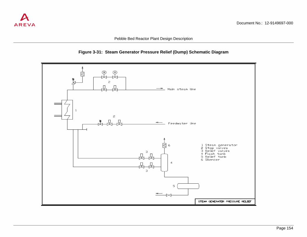
Document No.: 12-9149697-000
Pebble Bed Reactor Plant Design Description
Page 154
PROPRIETARY
Figure 3-31: Steam Generator Pressure Relief (Dump) Schematic Diagram
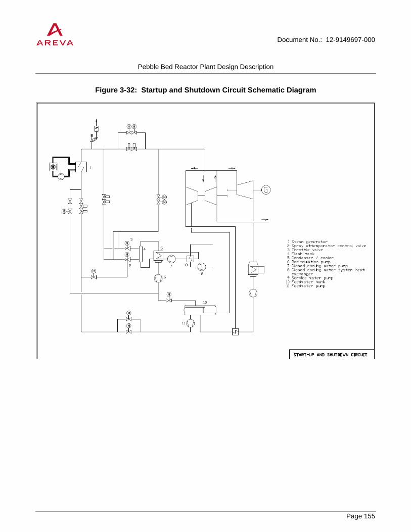
Document No.: 12-9149697-000
Pebble Bed Reactor Plant Design Description
Page 155
PROPRIETARY
Figure 3-32: Startup and Shutdown Circuit Schematic Diagram

Document No.: 12-9149697-000
Pebble Bed Reactor Plant Design Description
Page 156
PROPRIETARY
3.9 Cooling Water Systems
3.9.1 General Systems Configuration
The general flow diagrams (Figure 3-33 and Figure 3-34) show the inter-relationship among the following cooling water systems:
• Circulating water system and wet/dry cooling tower
• Closed cooling water systems
o Conventional closed cooling water system
o Operational component cooling system
o Secured cooling system
o Closed cooling water system for the startup and shutdown circuits
• Service water systems
o Conventional service water system
o Nuclear service water system
o Secured service water system
o Service water system for the startup and shutdown circuits
Water for the cooling water circuits (circulating water and service water systems) is taken from the mechanically cleaned (coarse and fine bar screens and traveling screen) and filtered (gravel filter) cooling water supply. This is also used for make-up water for these systems.
The circulating water system is a recirculation system using a wet/dry cooling tower. The circulating water passes from the cooling tower basin to the circulating water pumps. These pump the water through the condensers of the condensing turbines and back to the cooling tower. It passes first through the dry and then the wet section back into the cooling tower cold water basin thereby transferring the heat from the turbine condensers to the updraft of air.
In addition to the circulating water system, the conventional and nuclear service water and the service water for the startup and shutdown circuits also passes through the wet/dry cooling tower.
The circulating water system, the service water system and closed cooling water system for the startup and shutdown circuits, the conventional service water system and closed cooling water system as well as the nuclear service water system and operational component cooling system are all non-safety-related because they serve only cooling loads which do not have safety functions.
The secured service water system, together with the secured cooling system is arranged in two trains and is recirculation-cooled by two separate in-line wet induced-draft cooling towers.

Document No.: 12-9149697-000
Pebble Bed Reactor Plant Design Description
Page 157
PROPRIETARY
3.9.2 Circulating Water System with Wet/Dry Cooling Tower
3.9.2.1 Circulating Water System
The circulating water system transfers the heat extracted from the condensers to the atmosphere by means of a forced draft wet/dry cooling tower. Design data is shown in Table 3-23.
The four circulating water pumps deliver the circulating water from the cooling tower cold water basin through one circulating water supply main to each of the turbine condensers and back through the circulating water return main to the dry section of the wet/dry cooling tower. The water then passes to the distribution system and falls back into the cooling tower coldwater basin, transferring the heat absorbed in the turbine condensers to the up draft of air.
The function of the circulating water system and cooling tower is non-safety-related, and power is therefore supplied from the normal auxiliary network.
3.9.2.2 Wet/Dry Cooling Tower
Function
During wet/dry operation, the water to be cooled enters the top of the tubular heat exchanger of the dry section. After passing through the dry section, the partially cooled water is sprayed into the second stage, the wet section, for cooling to the final temperature.
The air flows in the dry section are in cross counter flow to the water and in counter flow in the wet section; both air streams merge below the fan.
The following operating modes are possible:
• Wet mode
• Wet/dry mode
• Dry mode
The dry section is shut down during the summer and the unit operates entirely as a wet cooling tower. The damper doors for the dry section are closed and the openings into the wet section are opened wide.
In the transition phase from the warm to the cold season, the dry section is gradually placed in service. The dry cooling proportion of the total heat removal is thus regulated so that no visible plume appears at the diffuser rim.
If visible plumes form as the ambient air temperature continues to fall with the dry section fully open, the wet stage is run back until recondensation in the cooling tower exhaust air ceases. The wet section also has to be run back to avoid icing of the fill grids at low ambient air temperatures.
Recirculation cooling is effected by convection and evaporation. To avoid unacceptable solids concentration in the circulating water, a portion of the flow is blown down. Evaporation losses, drift losses and the blow down flow are compensated for by make-up water.
Cooling Tower Dry Section

Document No.: 12-9149697-000
Pebble Bed Reactor Plant Design Description
Page 158
PROPRIETARY
The heat exchange elements of the dry section in the upper portion of the wet/dry cooling tower are polyethylene tube bundles.
Cooling Tower Wet Section
The wet section, in the lower half of the cooling tower, is provided with conventional polypropylene fill grids. It is designed for 100% heat removal so that in summer only wet operation is necessary.
Plume Control Equipment
The internals required for mixing the airflows from the wet and the dry section are located behind the heat exchanger units. The plume control equipment consists of V-shaped inward and upward sloping channels which guide the dry air into the central region of the cooling tower. Isobaric mixing of the two cooling air streams occurs on their outside edges due to turbulence.
3.9.3 Closed Cooling Water Systems
The closed cooling water systems include the conventional closed cooling water systems, the operational component cooling system and secured cooling system and closed cooling water system for startup and shutdown circuits. These are described below.
3.9.3.1 Conventional Closed Cooling Water Systems
The conventional closed cooling water system transfers the heat dissipated by cooling loads such as
• Chillers
• Turbine (including generator)
• Feedwater pumps
to the conventional service water system.
The design data are as follows:
• Cooling water mass flow 210 kg/s
• Cool temperature 34 °C
• Return temperature 46 °C
• Operating Pressure (approx.) 5 bar
• Nominal design pressure 10 bar
The conventional closed cooling water system is a closed circuit. It consists of two circulation pumps, two heat exchangers, a surge tank, interconnecting piping and valves. The components are installed in the turbine building. During normal operation and startup or shutdown of the plant, one circulation pump delivers water to a header for distribution to the various components.

Document No.: 12-9149697-000
Pebble Bed Reactor Plant Design Description
Page 159
PROPRIETARY
After flowing through the individual components the warm water is delivered to the two heat exchangers by a return header.
Demineralized water is used in the closed cooling water system. The oxygen content of the demineralized water is limited to inhibit corrosion.
A surge tank is provided on the suction side of the circulation pumps to equalize the flow within the system. Filling of the system and leakage make-up is performed by drawing water from the demineralized water supply according to the water level in the surge tank.
The conventional closed cooling water system is not safety-related. The electric motors are therefore connected to the normal auxiliary power supply.
3.9.3.2 Operational Component Cooling System
The operational component cooling system transfers the heat dissipated cooling loads such as
• Main circulator
• Coolers and circulators in the helium purification system
• Fuel handling system
• Liquid waste system
to the nuclear service water system.
The design data are as follows:
• Cooling water mass flow 60 kg/s
• Cool temperature 34 °C
• Return temperature 46 °C
• Operating Pressure (approx.) 5 bar
• Nominal design pressure 40 bar
In addition to the above named components the operational component cooling system also supplies the third train of the cavity cooler, provided for reasons of availability, the support coolers for the pressure vessel unit as well as the cooler of the nozzle in the reactor vessel bottom head (fuel discharge tube).
The operational component cooling system is a closed circuit. It consists of two circulation pumps, two heat exchangers, a surge tank, interconnecting piping and valves. The components are installed in the reactor building and reactor building annex. During normal operation and startup/shutdown of the plant, one circulation pump delivers water to the various components via a header.

Document No.: 12-9149697-000
Pebble Bed Reactor Plant Design Description
Page 160
PROPRIETARY
After flowing through the individual components the warm water is delivered to the two heat exchangers via a return header.
Demineralized water is used in the cooling system. The oxygen content of the demineralized water is limited to inhibit corrosion.
A surge tank is provided on the suction side of the nuclear component cooling pumps to equalize the flow within the system. Filling of the system and leakage make-up is performed by drawing water from the demineralized water supply according to the water level in the surge tank.
The operational component cooling system is not safety-related. Electric motors are therefore connected to the normal auxiliary power supply.
3.9.3.3 Secured Cooling System
3.9.3.3.1 System Description
The secured cooling system transfers the heat dissipated by the following loads to the secured service water system:
• Cavity cooler
• Supports for pressure vessel unit
• Nozzle in the reactor pressure vessel bottom head (fuel discharge tube)
The design data are as follows:
• Cooling water mass flow 20 kg/s
• Cool temperature 34°C
• Return temperature 46°C
• Operating pressure (approx.) 5 bar
• Nominal design pressure 40 bar
This system must be operational during startup, normal operation, shutdown, under emergency power conditions and in the event of accidents.
The secured cooling system is a closed circuit in a two-train configuration. Each train consists of a heat exchanger, a circulation pump, a surge tank, interconnecting piping and valves. The components of this system are installed in the reactor building and the reactor building annex.
Demineralized water is used in the secured component cooling system. The oxygen content of the demineralized water is limited to inhibit corrosion.

Document No.: 12-9149697-000
Pebble Bed Reactor Plant Design Description
Page 161
PROPRIETARY
A surge tank is provided on the suction side of the secured cooling system pumps to equalize the flow within the system.
In the event of loss of auxiliary power, the electric motors are powered by the emergency power supply.
The components and piping of the system are designed for earthquake. All cooling loads and piping to the fire brigade connections are designed for aircraft crash and blast wave. In the event of failure of the secured cooling train, the above cooling loads may be cooled with water injected at the fire brigade connections.
3.9.3.3.2 Cavity Cooler and other Cooling Loads of the Secured Cooling System
Dissipated heat must be removed from the primary cavity during normal operation. This includes the heat transmitted into the reactor cavity or its surrounding walls from the uninsulated part of the reactor pressure vessel by radiation and convection, the heat transmitted through the supports of the pressure vessel unit and from the fuel discharge tube. In the event of loss of main heat transfer system function, the cavity cooler installed in the reactor cavity removes the residual heat from the reactor.
Design, Boundary Conditions
A three-train configuration is used for all cooling loads. Two trains are served by the secured cooling system and one by the operational component cooling system. Each of these three trains is designed to handle the cooling loads.
The secured cooling system is additionally able to remove the thermal energies of other operational cooling loads.
For each reactor, the following thermal energy must be removed:
• From the cavity cooler in normal operation approx. 400 kW
• From the cavity cooler in residual heat removal operation approx. 850 kW
• From supports of the pressure vessel unit approx. 5 x 5 kW
• From the fuel discharge tube approx. 6 kW
The cavity cooler is subject to a maximum heat flux during power operation of approximately 1.5 kW/m² and in residual heat removal operation approximately 3 kW/m².
Cavity cooler
Refer to Section 3.4.2 for a discussion of residual heat removal by the cavity cooler.
The cavity cooler surrounds the reactor pressure vessel at a distance of approximately 1.5 m. It takes the form of a closed tube wall and is attached at a distance of approximately 10 cm inside the concrete wall of the reactor cavity. The space between cavity cooler and concrete is sealed to prevent ingress of hot air streams.
The tubes are installed vertically and joined by welding to form a welded membrane panel wall. Three inlet headers are located in the lower section of the reactor cavity and three outlet headers in the upper section. The inlet and outlet piping is routed separately through the wall of the reactor cavity. It is therefore possible to isolate each cooling train from a safely accessible point.

Document No.: 12-9149697-000
Pebble Bed Reactor Plant Design Description
Page 162
PROPRIETARY
The three-train configuration is achieved by joining every third tube to the same inlet and outlet headers. This enables even heat removal from the entire circumference in the event of the failure of one or two trains.
Other cooling loads in the primary cavity
The supports for the pressure vessel unit are water-cooled. In keeping with the multi-train configuration, the cooling loads each have three inlet and outlet headers which are connected to the corresponding cavity cooler headers.
The nozzle for the fuel discharge tube is insulated inside the reactor cavity and cooled in the area of the penetration through the base of the reactor cavity. For this purpose, U-shaped cooling water tubes are located in the space between the reactor pressure vessel nozzle and the shielding concrete liner tube. The free space below is filled with granular shielding material. The cooling water supply is arranged in three trains.
3.9.3.4 Closed Cooling Water System for Startup and Shutdown Circuits
The closed cooling water system for the startup and shutdown circuits removes heat from the condenser/coolers of the startup and shutdown circuits.
It runs in the following operating modes:
• Operational startup and shutdown
• Operational residual heat removal
• Disconnection and reconnection of a reactor during power operation.
The design data are as follows:
• Cooling water mass flow 446 kg/s
• Cool temperature (approx.) 64 °C
• Return temperature (approx.) 88 °C
• Operating Pressure (approx.) 10 bar
• Nominal design pressure 16 bar
If a smaller heat load must be removed, the cool and return temperatures and their temperature spread decrease.
The cooling system for the startup and shutdown circuits is a closed circuit. It consists of two closed cooling water system pumps, two closed cooling water system heat exchangers, a surge tank, piping and valves. The components are installed in the turbine building.
Both closed cooling water system pumps are run in the operating modes listed above and feed water to the condenser/cooler in operation via a header. After flowing through the condenser/cooler the warm water passes through a header to the two closed cooling water system heat exchangers.

Document No.: 12-9149697-000
Pebble Bed Reactor Plant Design Description
Page 163
PROPRIETARY
Demineralized water is used in the closed cooling water system. The oxygen content in the demineralized water is limited to inhibit corrosion.
A surge tank on the suction side of the closed cooling water system pump equalizes the flow in the system. Filling of the system and leakage make-up is performed by drawing water from the demineralized water supply according to the water level in the surge tank.
The closed cooling water system for the startup and shutdown circuits is not safety-related. The electric loads are therefore connected to the normal auxiliary power supply.
3.9.4 Service Water Systems
The service water systems circulating through the wet/dry cooling tower are as follows:
• Service water systems for the startup and shutdown circuits
• Service water system for the conventional plant
• Operational service water system for secured and operational cooling systems
The service water pumps of the service water system for the startup and shutdown circuits and the operational and conventional service water pumps are located in the pump structure alongside the circulating water pumps.
Individual induced-draft cooling towers provide cooling for the secured service water system.
The design data of the service water systems are listed in Table 3-24.
3.9.4.1 Service Water System for the Startup and Shutdown Circuits
The service water pumps transfer the cooling water from the pump structure through a header pipe to the closed cooling water system heat exchangers in the turbine building. After flowing through the closed circuit cooling water heat exchangers, the warm service water is cooled in the wet/dry cooling tower.
The service water system for the startup and shutdown circuits is not safety-related and is therefore connected to the normal auxiliary power supply.
3.9.4.2 Service Water System for Conventional Plant
The service water pumps transfer the cooling water from the pump structure to the conventional closed cooling water system heat exchangers in the turbine building via a header line. After flowing through the closed cooling water system heat exchanger, warm service water is cooled in the wet/dry cooling tower.
The service water system for conventional plant is not safety related and is therefore connected to the normal auxiliary power supply.

Document No.: 12-9149697-000
Pebble Bed Reactor Plant Design Description
Page 164
PROPRIETARY
3.9.4.3 Service Water System for Operational Component Cooling System
The service water pumps for the operational component cooling system transfer the cooling water from the pump house through a header to the operational component coolers in the reactor building annex. After flowing through the operational component coolers, warm service water is cooled in the wet/dry cooling tower.
The service water system for the operational component cooling system is not safety related and is therefore connected to the normal auxiliary power supply.
3.9.4.4 Service Water System for Secured Cooling System
The service water system for the secured cooling system is a two-train configuration.
The service water for the secured cooling system is recirculation-cooled in separate induced-draft cooling towers.
The service water pumps for the secured cooling system supply the secured cooling system heat exchangers in the reactor building annex.
The service water system for the secured cooling system is supplied from the emergency power supply because it is safety-related. The system is designed for earthquake.

Document No.: 12-9149697-000
Pebble Bed Reactor Plant Design Description
Page 165
PROPRIETARY
Table 3-23: Circulating Water System with Wet/Dry Cooling Tower
Parameter Value Cooling water mass flow 2 x 1400 kg/s Cold water temperature 27°C Warm water temperature 38°C Cooling range 11 K Damp air temperature 16°C Waste heat 2 x 71 MW Condenser pressure 0.1 bar Operating pressure (approx.) 2.5 bar Nominal design pressure 10 bar

Document No.: 12-9149697-000
Pebble Bed Reactor Plant Design Description
Page 166
PROPRIETARY
Table 3-24: Service Water System Design Data
System Flow Temperature Pressure Cool Return Operating Design
Conventional service water system 230 kg/s 27°C 38°C 2.5 bar 10 bar Nuclear service water system 82 kg/s 27°C 38°C 2.5 bar 10 bar Service water system for startup and shutdown circuits
1070 kg/s 27°C 38°C 2.5 bar 10 bar
Secured service water system 38 kg/s 28°C 39°C 2 bar 10 bar
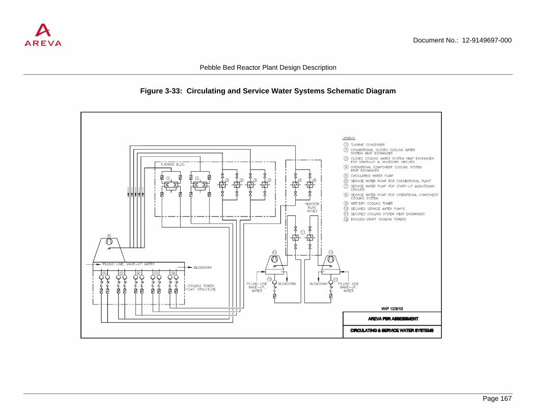
Document No.: 12-9149697-000
Pebble Bed Reactor Plant Design Description
Page 167
PROPRIETARY
Figure 3-33: Circulating and Service Water Systems Schematic Diagram

Document No.: 12-9149697-000
Pebble Bed Reactor Plant Design Description
Page 168
PROPRIETARY
Figure 3-34: Closed Cooling Water System Schematic Diagram

Document No.: 12-9149697-000
Pebble Bed Reactor Plant Design Description
Page 169
PROPRIETARY
3.10 HVAC Systems
The HVAC systems are divided according to the use of the buildings. The Nuclear HVAC systems serve the controlled area in the reactor building and the reactor auxiliary building and the conventional HVAC systems serve the conventional balance of plant.
The HVAC systems are cooled by the Conventional Chilled Water System. The air conditioning system of the central control room, computer and electronic equipment rooms are cooled by the Secured Chilled Water System.
3.10.1 Nuclear HVAC Systems for the Controlled Area
3.10.1.1 Design of Nuclear HVAC Systems
The Nuclear HVAC Systems in the controlled area perform the following functions:
• Supply of fresh air to the buildings.
• Maintenance of specified air conditions in compartments.
• Maintenance of sub-atmospheric pressure and directions of flow.
• Heat removal from mechanical and electrical equipment.
• Removal of air-borne radioactive gases and aerosols by purging and filtering.
• Controlled venting of filtered exhaust air to minimize environmental impact.
For depressurization accidents, the systems provide pressure relief from the reactor building and the helium tract in the reactor auxiliary building via pressure relief ports to atmosphere.
For the purposes of ventilation, the controlled area in the reactor and reactor auxiliary buildings is subdivided as follows:
• Reactor building primary cavities
• Reactor building equipment and service compartments
• Reactor building services tract and reactor hall including the reactor building annex area containing the cooling systems
• Reactor auxiliary building equipment compartment (helium tract)
• Reactor auxiliary building equipment compartments (water tract)
• Reactor auxiliary building laboratory and common rooms
Ventilation of reactor building and reactor building annex (component cooling system area)

Document No.: 12-9149697-000
Pebble Bed Reactor Plant Design Description
Page 170
PROPRIETARY
All compartments in the reactor building, with the exception of the primary cavities, are accessible during normal operation. Conditioned fresh air is supplied to all compartments except the primary cavities to maintain the required compartment air quality and to remove heat. The exhaust is extracted from areas where the possibility of contamination is greater than in the adjacent compartments. Extraction from the primary cavities is confined to removal of inleakage (approximately 2000 m3/d), so that the lowest pressure level in the reactor building is maintained in the primary cavities. This form of flow control ensures a directional air flow from compartments of low activity into compartments of higher activity.
The desired sub-atmospheric pressure is maintained by regulating the air intake flow for a constant extraction rate from the equipment and service compartments and the service tract. In normal operation the exhaust air is released unfiltered via the vent stack to atmosphere. During repairs or overhauls the exhaust air from the area concerned can be switched to the exhaust filter unit. Following accidents involving activity releases the area concerned is switched to the secured sub-atmospheric pressure system.
Compartments having large thermal burdens, such as the fuel discharge compartment and the equipment compartments, are provided with recirculation air coolers where required.
In the event of a break in a primary coolant-carrying pipe or water/steam cycle line, depressurization occurs into the reactor hall, and to atmosphere via two pressure relief ports.
Ventilation of reactor auxiliary building
The reactor auxiliary systems (except the fuel handling equipment described in Section 3.6), laboratory, and common rooms are located in the reactor auxiliary building. The principle of directional air flow governs air intake and extraction. The required sub-atmospheric pressure is maintained by regulating the air intake for a constant exhaust rate. The air exhausted from the equipment compartments (helium tract or water tract) areas can be switched to the exhaust air filter system if required. After accidents involving activity releases in the area of equipment compartments (helium tract) the area concerned is switched to the secured sub-atmospheric pressure system. The exhaust air from the laboratory and common rooms is released without being filtered. For the postulated break of a pipe in the helium purification system in the reactor auxiliary building pressure is relieved to atmosphere via a pressure relief duct.
Air-borne activity monitoring
The radioactivity of the extracted air from the Nuclear HVAC systems is monitored. For this purpose, portions of the exhaust air flow are bypassed through a sampling pipe network to activity monitors. The measurements are indicated in the air-borne activity monitoring compartment and some in the central control room as well.
3.10.1.2 System Description
Table 3-25 contains design data for the Nuclear HVAC Systems. Figure 3-35 provides a schematic diagram of the Nuclear HVAC Systems.
Air Intake Unit
This equipment is constructed as a common air intake for the reactor building and the reactor auxiliary building. It provides all areas with the required amount of heated or cooled fresh air. It is installed in the reactor auxiliary building and consists essentially of an air heater, filter, cooler, fans, silencer, humidifier and a network of concrete or galvanized steel air ducts. From the air distribution compartment the supply air flows to the various areas via

Document No.: 12-9149697-000
Pebble Bed Reactor Plant Design Description
Page 171
PROPRIETARY
separate air ducts. A control damper in each line of ducts provides the required sub-atmospheric pressure. Fire dampers, which close in case of fire, are provided where air ducts penetrate fire barriers.
The supply air ducting in the two areas, equipment and service compartments, and service tract in the reactor building, are each provided with an isolation damper which is closed when required or after a depressurization accident.
Exhaust Air Unit
The exhaust air from the compartments is discharged to atmosphere via the vent stack. The exhaust air unit is located in the reactor auxiliary building and consists of fans, non-return dampers and the exhaust air duct network. In normal operation, the entire exhaust air flow from the controlled area is discharged unfiltered. Fire dampers which close in case of fire are provided where air ducts penetrate fire barriers.
Exhaust Air Filter Unit
An exhaust air filter unit consisting of prefilter, HEPA filter and booster fan make up the exhaust air unit described above. For repairs or overhauls during which radioactive aerosols could be released, the exhaust air from the area concerned switched manually to this exhaust air filter unit. The exhaust air filters are designed to handle an air flow of approximately 5.55 m3/s (11,800 cfm).
Pressure Relief
In the design of the reactor building, it is postulated that a primary coolant-carrying pipe or a water/steam cycle line can break. The overpressure resulting from this accident is relieved via pressure relief ports within the building into the reactor hall and to atmosphere. Pressure relief to atmosphere is via two physically separate pressure relief ports provided with pressure relief dampers which open at a pressure of 0.1 bar at the latest. One mechanically operated, normally open damper is provided downstream of each pressure relief damper. The pressure relief damper closes automatically when pressure has been equalized and the mechanically operated damper can be closed manually. This ensures HVAC system isolation and maintenance of sub-atmospheric pressure even if the pressure relief damper is stuck open. A pressure relief facility is also provided for the equipment compartments (helium tract) in the reactor auxiliary building.
Secured Sub-Atmospheric Pressure System
The sub-atmospheric pressure in the controlled area is governed by the air intake and exhaust units during normal operation. The secured sub-atmospheric pressure system is provided to minimize the release of activity into the atmosphere and to maintain sub-atmospheric pressure after accidents. This equipment is installed in the reactor auxiliary building and consists of:
• Fans
• HEPA filters
• Activated-carbon adsorbers
• Final filter
• Isolation dampers
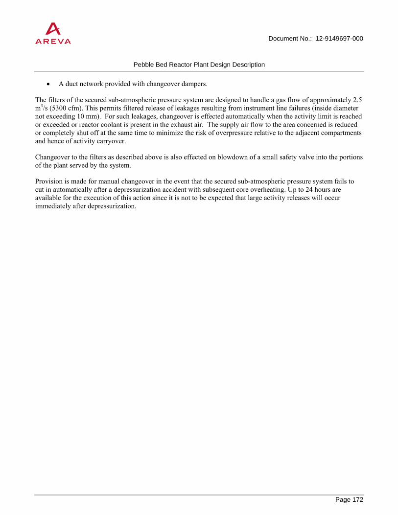
Document No.: 12-9149697-000
Pebble Bed Reactor Plant Design Description
Page 172
PROPRIETARY
• A duct network provided with changeover dampers.
The filters of the secured sub-atmospheric pressure system are designed to handle a gas flow of approximately 2.5 m3/s (5300 cfm). This permits filtered release of leakages resulting from instrument line failures (inside diameter not exceeding 10 mm). For such leakages, changeover is effected automatically when the activity limit is reached or exceeded or reactor coolant is present in the exhaust air. The supply air flow to the area concerned is reduced or completely shut off at the same time to minimize the risk of overpressure relative to the adjacent compartments and hence of activity carryover.
Changeover to the filters as described above is also effected on blowdown of a small safety valve into the portions of the plant served by the system.
Provision is made for manual changeover in the event that the secured sub-atmospheric pressure system fails to cut in automatically after a depressurization accident with subsequent core overheating. Up to 24 hours are available for the execution of this action since it is not to be expected that large activity releases will occur immediately after depressurization.

Document No.: 12-9149697-000
Pebble Bed Reactor Plant Design Description
Page 173
PROPRIETARY
Table 3-25: Principal Data for Nuclear HVAC Systems
Parameter Value
Air Intake Unit/Exhaust Air Unit Fans 2 x 100% Volumetric flow rate 30.5 m3/s (64,600 cfm) Power supply Normal system Exhaust Air Filter Unit Fan 1 x 100% Volumetric flow rate 5.55 m3/s (11,800 cfm) Power supply Normal HEPA filter Series S (DIN 24184) Separation efficiency 99.97% DOP Duty 2 x 50% Secured Sub-atmospheric Pressure System Fans 2 x 50% Volumetric flow rate 2.5 m3/s (5,300 cfm) Power supply Emergency system HEPA filter Series S (DIN 24184) Separation efficiency 99.97% DOP Duty 1 x 100% Activated-carbon adsorber Separation efficiency for methyl iodide 99%2 for elemental iodine 99.99% Duty 1 x 100%
2 The separation efficiency given is a minimum, and the duty conforms to BMI Guideline for iodine adsorption filter systems, 02.76 edition.

Document No.: 12-9149697-000
Pebble Bed Reactor Plant Design Description
Page 174
PROPRIETARY
Figure 3-35: Nuclear HVAC Systems

Document No.: 12-9149697-000
Pebble Bed Reactor Plant Design Description
Page 175
PROPRIETARY
3.10.2 HVAC Systems in the Switchgear and Emergency Supply Building
The HVAC systems in the switchgear and emergency supply building perform the following functions:
• Supply of fresh air.
• Maintenance of specified room temperature and humidity.
• Removal of waste heat from cables and electrical components.
• Extraction of fumes from the battery compartments.
• Controlled fume extraction in case of fire.
The building is subdivided into two sections for separation of redundant equipment. In accordance with this subdivision the configuration of the HVAC systems is as described below.
Table 3-26 contains design data for the HVAC systems in the switchgear and emergency supply building. Figure 3-36 provides a schematic diagram of the HVAC systems.
Air intake unit
The entire fresh air requirement of the building is conditioned in the air intake unit and supplied to the individual compartments by the recirculation units and to the air conditioning system of the central control room, computer and electronic equipment rooms. The air intake unit consists of an air heater, filter, cooler, fans and a concrete supply air duct. All compartments which are not supplied from the recirculation units for the associated sections of redundant equipment or from the air conditioning system for the central control room, computer and electronic equipment rooms are connected to the common air intake unit.
The chilled water supply of the air intake unit is performed by conventional chilled water system.
Exhaust air unit
Like the air intake unit, the exhaust air unit serves for the entire building. It consists of fans, dampers and the exhaust air header duct. In normal operation a portion of the air flow from the recirculation units equal to the amount of fresh air taken in is discharged in order to achieve the prescribed air change rate.
For fume removal, the entire exhaust air from the affected section of the building is discharged to atmosphere by the exhaust air unit. For this purpose the supply and exhaust air dampers for this section are fully opened and the recirculation fan is cut out. The exhaust air damper in the compartment containing the seat of the fire remains shut, the smoke venting and supply air dampers (or door) are opened manually. During this period only recirculated air is available for the other compartments. To increase the air change rate, the second exhaust air fan can also be cut in. The fans are designed for operation at high temperatures (approximately 250°C) to cope with the special requirements for fume extraction.
Air recirculation units
The air recirculation units for the two building sections operate at a fixed fresh air fraction. Each unit consists of a fan, a cooler and an air filter. The supply air is drawn in through vertical concrete shafts and supplied to the

Document No.: 12-9149697-000
Pebble Bed Reactor Plant Design Description
Page 176
PROPRIETARY
various levels of the building where it is distributed through galvanized steel air ducts. The exhaust air is extracted from the compartments and passed to the suction side of the central air recirculation unit also via vertical concrete shafts.
The chilled water supply of the air recirculation units is performed by the conventional chilled water system.
In the event of failure of one air recirculation unit, ventilation of the affected section of the building can be maintained by the air intake and exhaust units.
In the event of loss of power, the air recirculation units do not operate. However, the diesel generators are cooled by the engine radiator using fresh air.
Air conditioning unit for central control room, computer and electronic equipment rooms
The air used in the control room complex must satisfy the requirements for the well-being of the control room staff and the specified air conditions for the process computer and the electronic equipment rooms and the control station of the diesels. This equipment is therefore a multizone air conditioning unit with a fixed fresh air fraction. It consists of:
• Air humidifier
• Air cooler
• Fans
• Filter
• Reheating coil
• Silencer
• Air duct network for air distribution.
In normal operation and under emergency power conditions the coolers are supplied from the secured chilled water system in the switchgear and emergency supply building. Two air-cooled water chillers provide the required chilled water. The chiller compressors and fans draw power from the emergency power supply.
The air recirculation unit operates at a fixed fresh air fraction in normal operation. In the event of failure of one of the air recirculation units of the two sections, the air intake unit is switched to the affected section and the air conditioning unit for the central control room, computer and electronic equipment rooms goes into recirculation-only mode. In the event of failure of the entire air conditioning system, limited ventilation can be maintained by using the common air intake and exhaust units.
Ventilation of battery compartment
One battery compartment supplying power to the secured direct current loads is provided in each of the two sections of the building. One extraction fan is provided in each battery compartment to remove the fumes generated during battery charging; the fan discharges to atmosphere above roof level. The supply air is drawn from the associated air recirculation unit.

Document No.: 12-9149697-000
Pebble Bed Reactor Plant Design Description
Page 177
PROPRIETARY
Figure 3-36: Switchgear and Emergency HVAC

Document No.: 12-9149697-000
Pebble Bed Reactor Plant Design Description
Page 178
PROPRIETARY
3.10.3 Ventilation of Remote Shutdown Station in the Reactor Building
The remote shutdown station ventilation system performs the following functions:
• Supply of fresh air
• Maintenance of specified room temperature and humidity
• Removal of waste heat from cables and electrical components
• Extraction of fumes from the battery compartment
A separate air conditioning unit with variable fresh air fraction (Figure 3-35) is provided for the remote shutdown station. If required, it can be run in recirculation-only mode.
The unit consists of isolation dampers, air heater, filter, cooler, air intake fans (2 x 100%-duty), dampers, sheet metal duct network and exhaust air fans (2 x 100%-duty). One of each pair of fans draws power from the normal/emergency power supply system and the other is battery-powered.
The chilled water supply of the ventilation of Remote Shutdown Station in the Reactor Building is performed by conventional chilled water system.
A separate exhaust air fan discharges the battery compartment exhaust air to atmosphere.
In case of recirculation-only mode, the exhaust air fan is switched off.
The openings in the outside walls are provided with blast panels.

Document No.: 12-9149697-000
Pebble Bed Reactor Plant Design Description
Page 179
PROPRIETARY
Table 3-26: Principal Data of the HVAC System in the Switchgear and Emergency Supply Building and for the Remote Shutdown Station
Parameter Value Switchgear and Emergency Supply Building Supply air unit Fans 2 x 100% Volumetric flow rate 10.27 m3/s Power supply Normal system Filter Series EU 4 (DIN 24185) Exhaust air unit Fans 2 x 100% Volumetric flow rate 10.27 m3/s Power supply Normal system Central control room, computer and electronic equipment rooms
Fans 2 x 100% Volumetric flow rate 15.34 m3/s Power supply Emergency system Filter Series EU 7 (DIN 24185) Battery compartment exhaust air (2 times) Fans 1 x 100% each Volumetric flow rate 0.37 m3/s Power supply Emergency system Air recirculation units (2 times) Fans 1 x 100% each Volumetric flow rate 10.27 m3/s Power supply Normal system Remote Shutdown Station Air conditioning unit Supply air / exhaust air 2 x 100% Volumetric flow rate 0.55 m3/s Power supply 1 on emergency system 1 on emergency system (batteries) Battery compartment exhaust air Fan 1 x 100% Volumetric flow rate 0.16 m3/s Power supply Emergency system

Document No.: 12-9149697-000
Pebble Bed Reactor Plant Design Description
Page 180
PROPRIETARY
3.10.4 Other HVAC Systems
Other HVAC systems are of standard conventional design.
3.11 Plant Electrical Distribution System
The electric power systems supply power to the plant safety and non-safety equipment for normal plant operation, startup and normal shutdown, and for accident mitigation and safe shutdown.
The one-line diagram (Figure 3-37) shows a simplified arrangement of the plant electrical distribution system and components.
The two unit generators each feed into the 110 kV high voltage grid through their respective step up transformer. Under normal operation, one generator (G2) exclusively feeds into the grid while the second generator (G1) feeds into the grid and also provides the auxiliary power supply.
For normal startup and shutdown, auxiliary power is drawn from the 110 kV grid via generator G1 transformer. After synchronization of the generator with the grid the auxiliary power supply is taken from generator G1. In the event of loss of the 110 kV grid, the turbine generator set can continue to provide auxiliary power. In the event of loss of Unit 1 turbine generator set or reactor, the auxiliary supply is drawn from the grid via the generator transformer. If the generator transformer or the short-circuit limiter fails, the 10.5 kV standby offsite power supply will provide the required auxiliary power.
3.11.1 Auxiliary Power Supply
The auxiliary power supply provides electric power at 10.5kV, three-phase, and 690 V or less, three-phase and single-phase, to electrical switchgear to feed the plant's auxiliaries. The auxiliary power supply requirement is normally taken from one Generator G1. During outages auxiliary power will be taken from the 110 kV grid connection via short-circuit current limiters to two separate sections of the 10.5 kV busbar system. A second auxiliary power supply connection to the 10.5 kV site supply will be available in the event of a failure of the 110 kV grid supply.
The major auxiliary power loads and the transformers for the low-voltage distribution system are connected to the two 10.5 kV bus sections.
The arrangement of the 10.5 kV Medium Voltage (MV) switchgear allows supply of redundant equipment loads from separate buses and provides reliability and flexibility.
The MV switchgear supplies power to larger loads (motors, heaters, etc. 400 kW and over).
The 690 Vac low voltage (LV) distribution system supplies power to motors, heaters, etc. 132 kW to 450 kW.
The 400 Vac low voltage (LV) distribution system supplies power to loads 132 kW and below.
The 24 Vdc supplies power to the Remote Shutdown Station.

Document No.: 12-9149697-000
Pebble Bed Reactor Plant Design Description
Page 181
PROPRIETARY
3.11.2 Emergency Power System
The emergency power system supplies power to loads which are required for maintaining safe conditions in the event of loss of auxiliary power.
The following subsystems are provided in accordance with the requirements of the loads for continuity of power supply:
• 400 Vac emergency power supply for three-phase or single-phase alternating current loads, capable of accepting a break in supply while waiting for the emergency diesel generators startup after loss of auxiliary power.
• 220 Vdc power supply for DC loads, required to remain in operation without interruption on loss of auxiliary power or to be cut in during diesel startup.
• 400 Vdc inverter supply for three-phase or single-phase AC loads with the same supply needs as the above DC loads.
These subsystems are arranged in two trains and designed in accordance with the 2 x 100% redundancy requirements of the process.
Loads are assigned to the appropriate busbar systems according to the train to which they are allocated and according to their power supply requirements.
The output of one diesel generator set equals the maximum power demand of one train. The diesels are started automatically on loss of auxiliary power, a delay is introduced to prevent inadvertent diesel starts in the event of auxiliary power recovery or other short-term breaks in supply. The design of the HTR-Module also permits extended breaks in the 400 V emergency power supply. Diesels can be started at any time after loss of power.
The connection to the 400 Vac normal grid is automatically broken before a diesel start. Reconnection on return of the normal grid supply is effected manually.
Each diesel generator set is independent as regards the supply of fuel, lubricants and coolant, starting equipment, air intake and exhaust systems and its local control station.
The 220 Vdc charger units are designed for supplying the loads in the associated trains and also the diode-isolated loads in the adjacent train. This ensures that diode-isolated loads in both trains can be supplied with power during repairs.
The design of the batteries is such that, on loss of auxiliary power concurrent with postulated repairs, they provide an uninterruptible supply to the DC loads until load acceptance by the diesel generator sets.
With rectifiers unavailable, the 220 Vdc batteries can meet the demand of the associated section for at least 60 minutes.
The inverters are designed for the three-phase loads in the associated train requiring uninterruptible power supply.
The emergency power generating equipment and associated switchgear are located in the switchgear and emergency supply building and are designed for earthquake in accordance with the criteria ruling for this building. Fire breaks separate the redundant trains. Cross connections are reduced to the minimum necessary.

Document No.: 12-9149697-000
Pebble Bed Reactor Plant Design Description
Page 182
PROPRIETARY
A remote shutdown station is located in the reactor building for monitoring the plant on loss of central control room function. The loads in the remote shutdown station are supplied by connections with both 400V emergency power supplies in normal operation and, on their failure, from the 24V batteries in the reactor building. The equipment is in a single-train configuration. The batteries are designed to operate for 10 hours. Additionally, an ad hoc supply from a local source or from a mobile emergency generator is provided for by the installation of a 400V cable connection.
In normal operation the entire emergency power supply system draws power by connection of the 400 Vac normal to the 400 Vac emergency power busbars. The DC busbars are connected to the 400 Vac emergency power busbars through rectifiers and the inverter busbars are fed from the 220 Vdc busbar system through inverters.
The power supply for the computer systems is provided by the 400 Vac inverter busbars.
Batteries are connected in parallel with the incoming feeders of the DC busbars; they are constantly on standby and are kept fully charged by the rectifiers.
The three redundancies of the reactor protection system and the loads in the control and monitoring equipment are supplied from both trains through isolating diodes from the DC distribution boards.
The loads in the remote shutdown station are fed from the single-train supply equipment in the reactor building.
The batteries provide an uninterruptible supply to DC loads on loss of auxiliary power. The three-phase and single-phase AC loads requiring uninterruptible supply are fed from the inverters. On reaching speed, the emergency power diesel generators take over the direct supply of the 400 Vac emergency power loads and feed the remaining loads relying on the emergency power supply through rectifiers.
3.11.3 Grounding and Lightning Protection
Equipment grounding ensures personnel safety by connecting the plant's noncurrent-carrying metallic parts to the grounding grid. System grounding provides fast, selective clearing of the plant's ground faults to limit equipment damage.
Lightning Protection provides a metallic, low-impedance path to earth to direct lightning strokes, preventing lightning current from passing through the nonconductive parts of a building or structure in the plant.
3.11.4 Communication Systems
The Communication Systems provide separate, independent, and diverse types of intraplant communications between essential plant areas and the central control room and plant-to-offsite communications to locations remote from the plant during normal operation or under emergency conditions. Radio paging is also included in the design.
3.11.5 Alarm System
A single-train alarm system for transmission of various alarm signals is used.

Document No.: 12-9149697-000
Pebble Bed Reactor Plant Design Description
Page 183
PROPRIETARY
3.11.6 Lighting and Service Power System
The Lighting System provides normal ac and emergency ac and dc lighting to support plant activities. The Service Power System provides ac power to service outlets located throughout the plant for use with portable equipment, tools, and lighting.

Document No.: 12-9149697-000
Pebble Bed Reactor Plant Design Description
Page 184
PROPRIETARY
Figure 3-37: Electrical Distribution System One-Line Diagram

Document No.: 12-9149697-000
Pebble Bed Reactor Plant Design Description
Page 185
PROPRIETARY
3.12 Plant Instrumentation and Control Systems
The plant instrumentation and control systems perform the measurement, monitoring, and control of the plant. Instrumentation and control equipment is subdivided into operational systems, protection systems, and accident monitoring systems.
The operational instrumentation and control system is non-safety related and is used to operate the plant under normal conditions and to monitor operating conditions. Information required for monitoring operating conditions is displayed in the central control room.
The instrumentation and control equipment for the reactor protection system is safety-related and serves to prevent unacceptable loading on important components and systems and to minimize the effects of accidents upon the environment.
The equipment protection system is non-safety related and is designed to ensure automatic protection of important equipment units.
The accident monitoring system is safety related and ensures that adequate information is provided on plant conditions and on effects upon the plant and the environment during and after accidents and beyond-design basis event sequences.
Reactor control and shutdown systems are described in Section 3.2.4 and core instrumentation is described in Section 3.2.5.
3.12.1 Reactor Protection System
Each reactor in the HTR-Module has a separate, independent, and dedicated Reactor Protection System.
The reactor protection system (RPS) is required to monitor and process variables essential to the safety of reactor and the environment, to detect accidents and to automatically initiate protective actions. In the event of an accident, the reactor protection system shuts down the reactor and actuates the protective actions required for mitigation. The RPS has separate and redundant channels configured in such a way as to satisfy physical and electrical independence and separation requirements.
The monitored process variables, derivation of suitable initiation criteria and the generation of actuation signals for protective actions are performed based on the HTR-Module accident analyses.
In case of abnormal events, the protection system implements the automatic and manual actuation of safety systems and the relevant monitoring functions necessary to reach a controlled state by initiating reactor trip and starting the safety systems:
• Reactivity control;
• Residual heat removal;
• Limitation of radioactive releases at the site boundary to an acceptable limit and maintaining integrity of the primary and secondary systems.

Document No.: 12-9149697-000
Pebble Bed Reactor Plant Design Description
Page 186
PROPRIETARY
Each module has a dedicated reactor protection system. The RPS of each reactor in the module are independent from each other. Each include the data acquisition and automation of the:
• Reflector rods;
• Main circulator;
• Primary system isolation valves;
• Secondary system isolation valves;
• Steam generator relief valves
The RPS is designed to ensure that fulfillment of its safety functions is assured in the event of accidents occurring simultaneously with a postulated equipment failure or unavailability due to maintenance.
The reactor protection system is designed such that flooding, lightning, storms or earthquake cannot cause failure of subsystems.
3.12.2 Operational Instrumentation and Control System
The operational instrumentation and control system consists of process supervisory and control equipment for normal plant operation. Functions of operational control include plant power and load management, balance of plant and auxiliary subsystem control, energy conversion facility control, and general plant indication in both the control room, remote shutdown station, and at local control stations where appropriate.
Operational control is comprised of distributed control systems and subsystems such as fire protection, plant data, and equipment monitoring.
3.12.3 Accident Monitoring System
The accident monitoring system includes control room indication and plant instrumentation for the monitoring system plant conditions during and after an accident.
• Sufficient information on the condition of the plant to enable additional measures to be taken if required;
• An overview of automatically manually initiated protective actions and the plant response;
• Information for assessment of radiological effects upon the environment;
• Recording of the accident sequence for event reconstruction;
• Information to assist in determination of the loading sustained on important components.
The accident monitoring system consists of accident indication and recording equipment. The accident indication equipment is subdivided into accident surveillance, accident detail and wide range indication equipment.

Document No.: 12-9149697-000
Pebble Bed Reactor Plant Design Description
Page 187
PROPRIETARY
3.12.4 Main Control Room
The main control room provides central control for operation of the plant. It houses the operating and indicating equipment for managing and monitoring both reactors. Manual control, process setpoint adjustment and monitoring of the primary systems, the reactor auxiliary systems, the water/steam cycle, the turbines, the generators, the process steam system and the auxiliary power supply systems can be performed from the MCR as required.
Display equipment for the accident monitoring system and fire alarm systems are also located in the control room complex.
The main control room includes equipment for communication, measurement and recording required during and after accidents and beyond-design basis event sequences to;
• Provide adequate information on the condition of the plant to enable the required protective actions to be taken to protect personnel and equipment;
• Indicate and record trends;
• Permit assessment of any impact on the environment.
The main control room is equipped considering that the HTR-Module is provided with automated instrumentation and control equipment to satisfy safety and availability requirements. It relieves the personnel of the routine activities of normal running of the plant. Operators are able to intervene in the automated control process by means of the indication and control equipment provided in the main control room, remote shutdown station and local control stations.
3.12.5 Remote Shutdown Station
The remote shutdown station is provided as a second location for the display of safety-related information from the plant in addition to the main control room. It is located in the reactor building which is proof against external events. To ensure that access can be gained during the event sequences considered, a separate entrance from outside is provided. Operation of the remote shutdown station is not impaired by system failures in the switchgear and emergency power supply building. Equipment is designed to provide isolation of these controls and instrumentation. Electric power required for operation is provided by batteries designed to cover a period of 10 hours. If required, peripheral systems such as ventilation, lighting and communication can be supplied from these batteries.
The control action which can be initiated from the remote shutdown station is trip of the small ball shutdown system which transfers the reactor to a long-term subcritical condition. The remote shutdown station is not normally manned and is used for monitoring the plant in the event of loss of central control room function.
The remote shutdown station includes the following indications:
• Neutron flux (intermediate range);
• Primary system pressure;
• Moisture in reactor coolant;

Document No.: 12-9149697-000
Pebble Bed Reactor Plant Design Description
Page 188
PROPRIETARY
• Temperature of pressure vessel unit (wide range indication);
• Pressure in steam generator;
• Operation of the secured cooling system;
• Level in the storage vessels of the small ball shutdown system;
• Radiological data;
• Meteorological data.
These indications describe the condition of the plant from the safety standpoint and give information for any required actions to be taken or any radioactive releases. Recording of these variables permits reconstruction of an accident sequence.
Means of communications are provided in the remote shutdown station for voice contact with other parts of the plant and off-site.
3.13 Power Plant Auxiliary Systems
Numerous auxiliary systems are required to support plant operation. This section identifies the following systems and equipment:
• Cranes and elevators
• Compressed air system
• Demineralized water supply system
• Auxiliary steam system
• Space heating system
• Chilled water system
• Fire protection equipment
• Other balance of plant auxiliary sytems
3.13.1 Cranes and Elevators
An overhead traveling crane of all-welded steel construction is provided in the reactor building for assembly and overhaul work. The capacity is governed by the weight of the fuel element storage/shipping cask.
The reactor building crane has three hoists, the main hoist being designed for the storage/shipping cask and the auxiliary hoists for the largest equipment handling vessels. Variable-speed electric drives are used for all motors. The crane is operated from a mobile control board.

Document No.: 12-9149697-000
Pebble Bed Reactor Plant Design Description
Page 189
PROPRIETARY
Small hoists are provided in the reactor building for dismantling and maintenance of individual components. Fork lifts and trolleys are available for the movement of new fuel shipping casks.
The following additional cranes are provided for assembly and maintenance:
• Crane in reactor building vehicle entrance
• Crane in refueling station (reactor building)
• Crane for shipping cask covers (reactor building)
• Crane for failed fuel separator (reactor building)
• Crane in spent fuel store
• Crane in reactor auxiliary building erection compartment
• Crane in reactor auxiliary building entrance
• Crane in helium purification area (reactor auxiliary building)
• Crane in hot workshop
• Crane for decontamination compartment
• Crane spanning the electrical workshop (reactor auxiliary building)
• Turbine building crane
• Crane over feedwater pump bay (turbine building)
• Crane over feedwater tank bay (turbine building)
• Crane over erection hatch in the switchgear and emergency supply building
Elevators are provided in the reactor building, reactor auxiliary building, and turbine building.
3.13.2 Compressed Air System
A centralized compressed air supply is provided. Only operational loads are connected to the compressed air system. The compressors are located in the turbine building.
3.13.3 Demineralized Water Supply System
The demineralized water required for the various water and steam circuits is provided by a demineralizing system. The water is held in demineralized water storage tanks and is distributed by the demineralized water system.

Document No.: 12-9149697-000
Pebble Bed Reactor Plant Design Description
Page 190
PROPRIETARY
3.13.4 Auxiliary Steam System
The 4 bar steam manifold of the auxiliary steam system supplies the auxiliary steam loads of the plant under all operating conditions. The steam is required primarily for the space heating system, for the turbine seal steam system, and for the evaporator in the liquid waste processing system.
During operation of the plant, the required steam is taken from a steam extraction line. During outages and during startup and shutdown operation, auxiliary steam is supplied from an existing steam supply network.
3.13.5 Space Heating System
The space heating system provides space heating to plant buildings. Its primary loads are heat exchangers in the HVAC systems, hot water heaters, and heating panels and radiators.
3.13.6 Chilled Water System
Conventional chilled water system
The conventional chilled water system provides chilled water for cooling loads in the conventional and in the nuclear area (mainly HVAC heat exchangers). The chilled water required for normal operation is provided by chillers in the turbine building and is distributed to all chilled water loads in the power plant buildings via a common chilled water main. The working fluid is demineralized water. To inhibit corrosion of the heat exchangers and piping the oxygen content in the working fluid is monitored and controlled. The heat from the condensers of the chillers is removed by the closed cooling water system for conventional plant.
The operational chilled water system is a 2 x 100% design.
Secured chilled water system
A two-train (2 x 100%) chilled water system, one of which is a standby train, supplies the air-conditioning system for the control room and the computer and electronic equipment rooms in normal operation and under emergency power conditions. When required, changeover is effected manually.
For this reason, two small chiller sets with emergency power backup are located in the switchgear and emergency supply building.
The air-cooled condensers are located on the roof of the switchgear and emergency supply building.
3.13.7 Fire Protection Equipment
3.13.7.1 Fire Alarm System
Automatic alarm equipment
A fire alarm system with automatic fire detectors is used as an early fire warning system.
The installation of the automatic fire detectors considers the fire load and behavior of flammable materials, the significance to safety of components or equipment, personnel protection, and initiation criteria for fire protection equipment.

Document No.: 12-9149697-000
Pebble Bed Reactor Plant Design Description
Page 191
PROPRIETARY
The automatic fire detectors are connected to alarm lines and grouped so that:
• The location of the reported area is easily and immediately identifiable.
• A detector group extends over one level only (exception: stairwells, cable riser shafts, etc.).
• The area monitored by one alarm line may cover only one fire zone but may extend over several rooms/compartments separated by fire breaks if necessary.
• Detectors from inside and outside the control area may not be grouped together.
Manual alarms
Manual alarms (pushbutton alarms) within buildings are located outside doors and near landings of secure stairwells at the very least. Telephones are provided in these areas for direct communication.
Design and function of the fire alarm system
The system complies with the relevant regulations covering the design and operation of fire alarm systems. All fire and fault alarm signals received from fire alarms are annunciated visually and acoustically at the fire alarm central unit in the central control room complex. The alarm lines are monitored for continuity and ground faults by normally energized circuitry. The fire alarm system is powered by a battery which is trickle-charged by a rectifier from the emergency power supply.
3.13.7.2 Fire Fighting Equipment
Fire water supply
The fire water supply is designed to be capable of simultaneously supplying the largest stationary fire fighting system and hydrants in the open air or in the buildings with an additional water requirement of approximately 1600 L/min in total.
A ring main system is provided for fire water, fed from the existing fire water supply network and the site water supply via two permanent inlets. Sections of the ring main can be isolated (Figure 3-38) so that in the event of a break at any point in the ring main, an adequate supply of fire water is available for the buildings.
A head of at least 3 bar is assured at all outlets for hydrants.
For drawing fire water from the ring main, there are yard hydrants in the open and wall-mounted hydrants in the buildings. Inside the buildings, foam water hydrants are provided in areas subject to oil fire hazard.
Fire fighting equipment
The fire fighting equipment complies with the relevant regulations and the appropriate standards. The units are designed so as not to be detrimental to the operability of safety equipment as a result of malfunction, damage, or improper operation.
Compartments containing considerable fire loads which are inaccessible by reason of inadequate smoke venting and heat extraction or high local dose rates (e.g., cable ducts) are provided with sprinkler systems, spray deluge or gas extinguishing equipment as appropriate.

Document No.: 12-9149697-000
Pebble Bed Reactor Plant Design Description
Page 192
PROPRIETARY
The manner of actuation of stationary fire fighting equipment (automatic, manual in situ, or remote manual) is established as appropriate for the type of extinguisher and the local conditions in the area.
Spray deluge/sprinkler systems are supplied from two trains of the fire water system, so as to ensure a supply of fire water in the event of failure of one train. The valve stations for spray deluge/sprinkler systems are located outside the area served.
Fire fighting equipment (small mobile appliances)
Fire extinguishers are provided for fighting fires at the source. They are grouped at suitable points along the escape routes at intervals of no more than 40 m.
3.13.7.3 Fire Protection for HVAC Systems
The spreading of fire between fire zones and fire suppression zones is prevented by appropriate duct design or by the provision of fire dampers. Operability of HVAC systems is ensured for the central control room and remote shutdown station complexes even when an adjacent fire zone (except fire in the associated HVAC system) is on fire.
Secure escape routes, like the necessary stairwells, are kept free from smoke by natural convection or forced draft systems.
Local fire fighting is supported by the provision of suitably designed mobile and, in some instances, stationary smoke venting systems.
The HVAC system provided may also be used for the venting of cold smoke.

Document No.: 12-9149697-000
Pebble Bed Reactor Plant Design Description
Page 193
PROPRIETARY
Figure 3-38: Fire Water System

Document No.: 12-9149697-000
Pebble Bed Reactor Plant Design Description
Page 194
PROPRIETARY
3.13.8 Other Balance of Plant Auxiliary Systems
Various other conventional systems are required for a complete power plant. The following functional systems are not described in the HTR-Module Safety Analysis Report that serves as the basis for this design description, but are representative of balance of plant systems expected to be supplied as part of a complete power plant design. The systems are not described but are identified to support the PBR cost estimate report.
• Water systems
o Raw water system
o Potable water system
o Sanitary wastewater system
o Storm water system
• Monitoring systems
o Environmental monitoring system
o Radiation monitoring systems
• Gas storage and supply system
• Auxiliary steam system
• Security system
3.14 Plant Structures
3.14.1 Overall Plant; General Layout
The general layout of the HTR-Module power plant is shown on the site general arrangement plan (Figure 3-39).
3.14.1.1 Layout of Structures
The main structures of the power plant are the:
• Reactor building with the reactor building annex
• Reactor auxiliary building
• Switchgear and emergency power supply building
• Turbine building
The service structures include the:

Document No.: 12-9149697-000
Pebble Bed Reactor Plant Design Description
Page 195
PROPRIETARY
• Spent fuel storage building
• Operations building
• Central gas supply systems building
• Cooling towers and cooling tower pump structures
• Other auxiliary structures such as the substation, demineralized water tanks, pipe bridges, yard electrical raceways, vent stack, etc.
The site general arrangement plan shows the general layout of these structures.
The reactor building is at the center of the overall plant and consists of largely replicated rectangular modular units.
The reactor building annex is part of the reactor building structure located outside the confinement boundary.
The reactor auxiliary building is directly adjacent to the reactor building. This arrangement is necessary to minimize the length of the many system connections and for personnel access. The reactor building and the reactor auxiliary building are separate structures whose interconnections can accommodate relative displacement.
The vent stack is supported by the reactor auxiliary building.
The spent fuel storage building and the central gas supply systems building are separate structures located a short distance from the reactor auxiliary building.
The switchgear and emergency power supply building is located to the side of and separate from the reactor building; its long side runs the full width of the reactor building. The switchgear and emergency power supply building, which houses the control room for the overall plant, is connected to the reactor building by raceways. The cable connections to the reactor auxiliary building and to the turbine building are in separate, non-intersecting raceways.
The turbine building is separated from the reactor building. The two turbine generators are installed with shafts parallel to each other, arranged to reduce the probability of turbine missiles striking the modular reactor buildings.
The cooling towers and cooling tower pump structures are located near the turbine building.
The main personnel entrance to the reactor building, the reactor auxiliary building, and the switchgear and emergency power supply building is via the operations building, which is adjacent to the switchgear and emergency power supply building. A bridge connects it to the reactor auxiliary building, through which the reactor building is reached. All structures with non-nuclear systems are accessible directly from yard areas.
The gate house is located at the main entrance to the plant.
3.14.1.2 Confinement Envelope
The confinement envelope of the HTR-Module acts in conjunction with other barriers to the release of radioactive substances to minimize the radiological impact on the environment of accident conditions.

Document No.: 12-9149697-000
Pebble Bed Reactor Plant Design Description
Page 196
PROPRIETARY
The following features contribute to the confinement function:
• Reactor building
• Secured subatmospheric pressure system
• Building pressure relief System, HVAC systems isolation
Because the fuel elements provide reliable retention of radioactive fission products, the confinement function is not required to comply with regulatory release limits. In principle, it is possible to discharge the primary coolant unfiltered directly into the environment in the event of accident-induced depressurization of the primary system. Nevertheless, to minimize the radiological impact on the environment of a depressurization accident, the escaping primary coolant is filtered in the secured subatmospheric pressure system before discharge from the vent stack. The design basis for the system is a primary system break with a diameter less than or equal to 10 mm.
For larger postulated breaks which lead to a significant pressure build-up in the reactor building, building pressure is relieved by direct discharge of primary coolant into the environment. After depressurization, the pressure relief ports are closed and further discharges via the secured subatmospheric pressure system can be filtered.
Reactor Building
No leak-tightness demands are made of the reactor building as part of the confinement envelope or of its penetrations and entrances. The maximum leakage of the reactor building is 50 vol.%/day with a differential pressure of 2 mbar. A subatmospheric pressure system and a pressure relief system are provided in the reactor building merely to minimize the impact on the environment after a postulated break in the primary system. The entrances to the building consist of interlocked doors, which assure that a directional air flow in the building can be maintained at all times.
Since it is possible to relieve building pressure directly into the atmosphere in the event of a depressurization accident, it is unnecessary to design the building for high interior pressures. The reactor building is designed for the pressures and temperatures which are postulated to occur in the event of a primary coolant pipe break or main feedwater line break and building pressure relief to the environment.
The primary cavities and outside walls of the reactor building are designed against a pressure of 0.3 bar. The shielding effect of the primary cavities provides reliable protection of the environment from direct radiation.
Secured Subatmospheric Pressure System
Areas containing primary coolant pipes are monitored for helium leakage. If specified limits are exceeded, the affected area of the building is switched from the unfiltered air exhaust system to the secured subatmospheric pressure system.
The secured subatmospheric pressure system is designed for a volumetric flow rate of 2.5 m3/s and receives emergency power backup. The system is equipped with a HEPA filter and an activated-carbon adsorber.
Building Pressure Relief System
The arrangement of the compartments in the reactor building and the HVAC Systems assure that air flows from rooms with low airborne activity levels into rooms with higher airborne activity levels in order to limit any spread of radioactive materials in the building under normal operating conditions.

Document No.: 12-9149697-000
Pebble Bed Reactor Plant Design Description
Page 197
PROPRIETARY
As far as possible, the secured subatmospheric pressure system is used to minimize radioactive releases in the event of accidents.
Relief ports fitted with rupture discs or dampers which connect the modular units with the reactor hall are provided to control depressurization accidents (DN 65). Building pressure is relieved into the environment via the vent stack. Each port is equipped with:
• A pressure relief damper which opens at a response pressure of approx. 0.1 bar and closes automatically after pressure equalization
• An isolation damper which is normally open and can be closed manually after a depressurization accident in case the pressure relief damper sticks open.
Subatmospheric pressure can thus be restored after pressure relief.
A pressure relief system, discharging to the vent stack, is also provided for the equipment compartments (helium tract) in the reactor auxiliary building.
3.14.1.3 Foundations, Groundwater Protection, Roofing, Heights of Essential Plant Buildings
The plant buildings relied on for safety are supported by mat-type reinforced concrete foundations. Adjacent buildings are separated by joints.
The reactor building and the reactor auxiliary building are protected against groundwater, as necessary, by a suitable sealing system. This seal against water at pressure is sized as appropriate for the groundwater elevation and load, taking into account local conditions. It is raised to plant grade level, including the upper flashing.
The exterior walls of the other buildings are made of water-tight cement up to plant grade level. Building penetrations in the area of the groundwater seal or through the water-tight cement are sealed against water at pressure.
All plant buildings have flat roofs. Roofing materials, thermal insulation and sealing details will be used as appropriate. Table 3-27 gives the heights of the essential plant buildings.
3.14.1.4 Controlled Area Boundaries, Personnel and Equipment Access
The controlled area for the HTR-Module design includes the following plant buildings:
• Reactor building (excluding the remote shutdown station)
• Reactor building annex (middle area only)
• Most of the reactor auxiliary building
• Spent fuel storage area (setdown positions and only when needed for handling fuel storage / shipping casks or inspections, the truck entrance and transport aisle)

Document No.: 12-9149697-000
Pebble Bed Reactor Plant Design Description
Page 198
PROPRIETARY
The main entrance to that portion of the controlled area comprising the reactor building and the reactor auxiliary building is in the reactor auxiliary building.
The reactor building and reactor auxiliary building each have two closed stairwells with exits to the outside. These exits fulfill the requirements for plant security and escape routes.
A truck entrance is provided for the transport of materials and equipment to the reactor auxiliary building. Transport within the reactor auxiliary building is through access aisles and hoistways with the aid of lifting gear or the service elevator.
Materials and equipment also are transported into the reactor building through the truck entrance of the reactor auxiliary building. The horizontal movement route and the hoistway in the reactor building are connected to this truck entrance by a driveway. The reactor building crane can reach all necessary destinations in the reactor building.
3.14.1.5 Escape Routes
Reactor Building
The two enclosed stairwells in the reactor building, which are located near the exterior walls, serve as personnel exits. From the first stairwell, personnel can reach the reactor auxiliary building through the double door of the controlled area entrance or the exterior through a direct exit. The second stairwell, next to the service elevator, exits to the exterior. The exits to the exterior are fire protected as necessary to conform to life safety requirements for escape routes.
Reactor Building Annex
The reactor building annex is divided, as appropriate to its functions, into three areas. The middle area is part of the controlled area. Three exits from this area lead to a fire protected stairwell in the reactor building. The remaining areas of the reactor building annex are provided with enclosed stairwells and exits to the exterior.
Remote Shutdown Station
The remote shutdown station has a fire exit to the outside.
Reactor Auxiliary Building
The two enclosed stairwells serve as escape routes to the exterior. All exits to the exterior are fire protected as necessary to conform to life safety requirements for escape routes.
Switchgear and Emergency Supply Building
Two enclosed stairwells near the exterior wall are provided as escape routes to the exterior. The exits to the exterior are fire protected as necessary to conform to life safety requirements for escape routes.
All rooms in which plant electrical equipment is installed are locked. In an emergency, personnel in these rooms can open any door from the inside with the panic hardware provided.
Turbine Building

Document No.: 12-9149697-000
Pebble Bed Reactor Plant Design Description
Page 199
PROPRIETARY
Three stairwells located on the outside of the building serve as escape routes with direct exits to the exterior.
Pump structures
A fire protected stairway leads from each structure to the exterior as necessary to conform to life safety requirements.
Other buildings and structures
Other plant buildings and accessible structures such as the spent fuel storage area, central gas supply systems building, cable tunnels, and pipe bridges are provided with escape routes and exits which conform to the applicable life safety requirements.
3.14.2 Reactor Building
The Reactor Building general arrangement is shown in Figure 3-40, Figure 3-41, Figure 3-42, Figure 3-43, Figure 3-44, and Figure 3-45.
3.14.2.1 Functions, Compartment Arrangement and Equipment Layout
The reactor building contains the primary system, important auxiliary and supporting systems and the remote shutdown station. An external shield structure envelopes the inner structure, fulfilling the requirement for protection of the reactor building internals from external events.
The reactor building is subdivided into the following areas:
• The two PBR modular units
• The services areas
• The erection floor and hall above it (reactor hall)
• The remote shutdown station
• The reactor building annex
The reactor building and reactor building annex are designed against the effects of earthquakes. The reactor building, not including the reactor building annex, is designed against aircraft and explosion blast wave loads. The outer walls and roof are sized to provide complete protection against an airplane crash. The inside structure is uncoupled from the outside structure; the only link between the two is the foundation slab.
At the center of the PBR modular units are the two primary cavities, each consisting of one reactor cavity and one steam generator cavity. These cavities enclose the pressure vessels. Beneath the reactor cavities are the fuel discharge compartments.
The primary cavities are surrounded by compartments with various functions. These compartments contain:
• Entrances to the primary cavities

Document No.: 12-9149697-000
Pebble Bed Reactor Plant Design Description
Page 200
PROPRIETARY
• Piping and valve stations of the water/steam cycle, the operational component cooling system and the safety-related component cooling system
• Transducers
• Service systems for the main circulator
• Auxiliary and supporting systems for the nuclear steam supply
The services areas consist of two distinct areas. One is between the modular units, the other is in front of them. The modular units are separated in such a way that maintenance and inspection can be carried out on one module while the other is in power operation.
The services areas contain:
• Portions of the fuel handling systems common to both modules, i.e., charge stations for new and partially depleted fuel elements, discharge station for spent and partially depleted fuel elements
• Remote shutdown station
• Principal components of air removal systems
• The two enclosed stairwells
• The elevator
The remote shutdown station is a separate group of compartments in the reactor building; it has a separate HVAC system. The remote shutdown station is accessed from a secure entrance during normal operation and on demand. The services areas are also accessible from the remote shutdown station.
The remote shutdown station includes the following rooms and compartments:
• The remote shutdown room with first aid equipment
• A power distribution board compartment
• A battery compartment
• An HVAC system and incoming feeder compartment
• An emergency equipment compartment
• A sanitary facilities room
The incoming connection for power supply and the hose connections for the secured cooling system (fire hydrants) are in the vicinity of the secure entrance from the exterior.
The reactor building is served by horizontal and vertical pipe and cable shafts and by equipment transport aisles and hoistways, and personnel traffic routes.

Document No.: 12-9149697-000
Pebble Bed Reactor Plant Design Description
Page 201
PROPRIETARY
The reactor building annex is outside the reactor building shield structure. It houses pumps and coolers of the operational and secured cooling systems, components of the steam generator relief system, and components of the startup and shutdown systems.
The following compartments in the reactor building have limited personnel accessibility during reactor operation:
• Primary cavities not accessible
• Equipment compartments accessible under certain conditions
• Service compartments accessible
The primary cavity contains the reactor pressure vessel unit with internals. The equipment compartments contain the fuel discharge system, fuel handling tube ducts and shafts, fuel handling valves, and the main steam inlet branch. The service compartments include the reactor hall, areas around primary cavities, large portions of the services areas, and the reactor building annex.
During normal operation, the HVAC system maintains a controlled flow of air from the service compartments through the equipment compartments to the primary cavities. Because of reliable retention of radioactive fission products in the fuel elements and the resulting low level of radioactivity in the primary coolant, there are no special leak-tightness requirements for the reactor building.
Piping and cable penetrations and entrances are designed in such a way as to assure maintenance of the prescribed airflow direction by the HVAC system.
Pressure relief parts which vent overpressure to the outside are provided to control building pressure in the event of a depressurization accident. The design pressure for the building is set at 0.3 bar.
3.14.2.2 Entrances and Stairways
During reactor operation, the reactor building is entered exclusively through interlocked doors from the controlled area entrance in the reactor auxiliary building.
All equipment transport operations necessary during operation for transferring heavy components, including fuel shipping casks, in and out of the reactor building are performed through the equipment hatch directly adjacent to the truck entrance in the reactor auxiliary building. The entrances for personnel and transport vehicles function as airlocks.
Two continuous, closed stairwells and various short stairways in the service compartments connect the seven main floors of the reactor building from elev. -12.70 m to elev. +25.4 m. Two stairwells provide access to the three floors of the reactor building annex. The middle part of the reactor building annex (controlled area) is connected to the reactor building by entrances.
Access to the remote shutdown station is gained through a secure controlled entrance from the exterior.
3.14.2.3 Compartment Habitability
During normal power operation, only a few persons are temporarily present in the reactor building for periodic monitoring activities, and to deliver new and remove spent fuel elements. All compartments accessible during

Document No.: 12-9149697-000
Pebble Bed Reactor Plant Design Description
Page 202
PROPRIETARY
normal operation serve solely for plant maintenance and repairs. There are no compartments that are continuously occupied.
The remote shutdown station can be occupied for longer periods of time if necessary.
3.14.2.4 Description of Civil Works
The reactor building is approximately 46 m long and approximately 36 m wide. Below plant grade level, the width including the reactor building annex is approximately 44 m.
The building has a mat foundation below plant grade, which makes the reactor building partially embedded in the subgrade. The bottom of the mat foundation is founded approximately at elevation -15.50 m.
The building’s internal structure is separated from the outer shield structure by flexible joints where sealing is needed in order to avoid transmission of forces due to external events.
The dimensions of the floors and walls of the reactor building conform to radiological protection (shielding) requirements, even where thinner floors and walls would be structurally adequate.
The reactor building and the reactor auxiliary building are separated by a joint at their boundary in order to compensate for differential settlement without restraint.
The thickness of the shield structure makes additional noise control and thermal insulation measures unnecessary.
3.14.3 Reactor Auxiliary Building
The Reactor Auxiliary Building general arrangement is shown in Figure 3-46, Figure 3-47, Figure 3-48, and Figure 3-49.
3.14.3.1 Functions, Compartment Arrangement, and Element Layout
The reactor auxiliary building contains auxiliary systems for the reactor system and the central monitored entrance to the controlled area. The arrangement and layout of the structure allow short connections to the reactor building.
The reactor auxiliary building and the reactor building are located in a common seal structure. The seal structure of the reactor auxiliary building and the main load-bearing structures that support it are designed to functionally survive an earthquake to prevent releases of radioactivity into the ground. The other main load-bearing structures of the reactor auxiliary building are designed to be stable at the intensity of the safe shutdown earthquake to prevent unacceptable effects on the seal structure and the adjacent reactor building.
The lowest level is at elevation -9.5 m. The building is constructed of 6 full floors and 1 partial floor.
The following systems are housed in the reactor auxiliary building:
• Helium purification system and helium supporting systems
• Systems for handling radioactive waste (storage and processing)

Document No.: 12-9149697-000
Pebble Bed Reactor Plant Design Description
Page 203
PROPRIETARY
• HVAC systems such as air intake and exhaust and the secured subatmospheric pressure system
Other facilities in the reactor auxiliary building are:
• New fuel storage
• Hot workshop
• Decontamination compartment
• Laboratories
• Stockrooms for parts and components
• Change rooms
In the event of an accident-induced pressure rise in the helium system areas, pressure is relieved by a pressure relief duct to the exterior.
3.14.3.2 Entrances and Stairways
The +7.0 m level of the reactor auxiliary building is dedicated to the facilities necessary for personnel traffic in the controlled area of the reactor building and the reactor auxiliary building. All persons entering and leaving the controlled area of the reactor building and the reactor auxiliary building are monitored.
Rooms are reached by means of central passageways on all floors. Two stairwells with direct access to the passageways join the floors to each other and provide exit routes.
An equipment transport entrance is located at a central point at elevation 0.0 m of the reactor auxiliary building and directly adjoins the equipment access aisle in the reactor building. The portion of the equipment access aisle in the reactor auxiliary building functions as an airlock for the equipment entrance into the reactor building.
The hot workshop, decontamination compartment and other important facilities in the reactor auxiliary building adjoin the truck entrance on both sides.
3.14.3.3 Compartment Habitability
The rooms which are constantly occupied in the reactor auxiliary building are the laboratory rooms and the controlled area with the adjoining change area (changing rooms, washrooms, shower rooms, and the hot laundry). Work is performed in the hot workshop and the decontamination compartment only if necessary. All other rooms are occupied for short periods of time for maintenance and repair purposes.
3.14.3.4 Description of Civil Works
The reactor auxiliary building is approximately 46 m long and approximately 26 m wide and has full below-grade floors.
The reactor auxiliary building is built on a reinforced concrete foundation mat separate from the adjoining foundation mat of the reactor building.

Document No.: 12-9149697-000
Pebble Bed Reactor Plant Design Description
Page 204
PROPRIETARY
The dimensions of the floors and walls conform to radiological protection requirements, even though thinner floors and walls would be structurally adequate. In addition, the exterior walls of the reactor auxiliary building are designed to provide the necessary thermal insulation.
The stairway enclosures are reinforced concrete.
In accordance with radiological protection requirements, some interior walls consist of prefabricated concrete shielding blocks, either set in mortar or dry-laid.
3.14.4 Turbine Building
The Turbine Building general arrangement is shown in Figure 3-50, Figure 3-51, and Figure 3-52.
3.14.4.1 Functions, Compartment Arrangement, and Equipment
The turbine building contains the two turbine generator sets and the components of the water/steam cycle. The structure has a main bay and a service bay. The main bay is divided into two replicated sections, each having one turbine-generator set and the associated components of the feedwater heating system, and an additional section containing the erection opening and the truck entrance. The service bay contains the feedwater tanks and feedwater pumps.
The upper level of the main bay is the turbine floor (elevation +9.5 m) and the hall above. It contains the turbine building overhead traveling crane. Intermediate platforms at elevation +5.2 m are provided where they are needed.
The circulating water lines, drains coolers, and components and piping of the conventional closed cooling water system are at elevation -4.0 m of the turbine building. The main cable runs to the cable riser shafts are in a cable tunnel also at this level.
The condensers are positioned transverse to the turbine axis approximately at elevation 0.0 m in the main bay. The feedwater pumps are located beneath an overhead crane in the service bay.
The low-pressure feedwater heaters are in the immediate proximity of the turbines. All of these vessels can be served by the turbine building overhead crane.
Piping and reducing stations are accommodated at elevations below the turbines. The turbine oil supply system with oil tank and pumps is in a separate fire-rated compartment on the intermediate platform in front of the turbine. The generator cooling system is beneath the generator. The generator leads are routed through the exterior wall of the building to the transformers.
The turbine floor is open and has laydown space for placing individual parts during maintenance and overhauls. The feedwater tanks are in the service bay at the turbine floor elevation. Above the feedwater tanks is the deaerator platform.
3.14.4.2 Entrances and Stairways
All material and equipment access during construction and operation is via the vehicle entrance at elevation +0.00 m. A full width construction opening enables rigging the largest components up to the turbine floor with the aid of the turbine building overhead crane.

Document No.: 12-9149697-000
Pebble Bed Reactor Plant Design Description
Page 205
PROPRIETARY
Personnel access to the turbine building is through doors at grade and stairwells.
The floors of the turbine building are reached by the three enclosed stairwells and an elevator.
3.14.4.3 Compartment Habitability
All areas of the turbine building are continually habitable.
3.14.4.4 Description of Civil Works
The turbine building is approximately 63 m long and 49 m wide overall, and has a full basement.
The building has reinforced concrete foundations.
The service bay runs the entire length of the turbine building and is approximately 9.00 m wide.
The turbine building's load-bearing structure up to the turbine floor at +9.50 m consists of a reinforced concrete skeleton. Ceilings and joists are made of in-situ concrete. The superstructure framing above the turbine floor at +9.50 m is structural steel.
The load of the turbine generator sets is transmitted into the low-tuned, reinforced-concrete girder grid foundations through spring assemblies on pedestals. Deformations can be monitored by an instrumentation and recording system.
The reinforced-concrete foundations for the feedwater pumps at elevation +0.00 m in the service bay are structurally isolated from the surrounding structural parts of the turbine building. The feedwater pumps are supported on spring assemblies.
The sheathing of the turbine building is designed to comply with noise control regulations and thermal insulation requirements.
3.14.5 Switchgear and Emergency Supply Building
The Switchgear and Emergency Supply Building general arrangement is shown in Figure 3-53, Figure 3-54, and Figure 3-55.
3.14.5.1 Functions, Compartment Arrangement, and Equipment Layout
The switchgear and emergency supply building contains switchgear and I&C systems which are arranged in separate compartments consistent with the requirements for physical separation of redundant SSCs. Each redundant section has its own cableways and HVAC.
The switchgear and emergency supply building is designed against the effects of earthquakes.
The building has five floors. The bottom floor comprises the cable spreading area, below which are the cable tunnels in the foundation slab. The next floor houses the switchgear, DC distribution boards, batteries, and diesel generators. The next floor is only for cables. The I&C cabinets are on one side of the floor above this. The control room with the control room annex, computer room, and anterooms are on the other side of the floor.

Document No.: 12-9149697-000
Pebble Bed Reactor Plant Design Description
Page 206
PROPRIETARY
A floor with compartments for the building HVAC systems is above the I&C cabinet floor. The building is supplied with fresh air through air intake and exhaust ducts by the HVAC system on the upper floor. An air conditioning system is provided for the control room, its annexes, and the I&C compartments.
In addition to ventilation ducts, the building has cable riser shafts. The cables are run out through the tunnels in the foundation slab to the turbine building and the pump structures, and in divided tunnels for each redundant train to the reactor building and reactor auxiliary building.
3.14.5.2 Entrances and Stairways
Personnel access to the switchgear and emergency supply building is from the operations building at the control room elevation.
There is an entrance for materials and equipment at grade. The diesel compartments have separate entrances. The five floors are reached through the two stairways at either end and the central corridor which runs the full length of the building. Materials and equipment can be transported to any floor through via the hoistway.
3.14.5.3 Compartment Habitability
The main control room floor can be continuously occupied. The other compartments are entered as needed for repair and maintenance.
The control room with its annex and anterooms has no windows. The requirements for a working environment are fulfilled by properly designed lighting and an HVAC system for these rooms.
3.14.5.4 Description of Civil Works
The switchgear and emergency supply building is approximately 39 m long and approximately 38 m wide and has a full basement.
The building has a reinforced concrete foundation mat.
The load bearing structure of the building consists of a reinforced concrete frame with reinforced concrete floors and walls.
The concrete exterior elements satisfy thermal insulation requirements.
3.14.6 Spent Fuel Storage Area
The Spent Fuel Storage Area general arrangement is shown in Figure 3-56.
3.14.6.1 Functions, Compartment Arrangement, and Equipment Layout
The spent fuel storage area can accommodate eight (8) fuel storage/shipping casks, corresponding to a storage capacity of 1 to 1.5 years of reactor operation. The building is designed to allow an extension of eight storage locations for storage of an entire core unloading. Additionally, the storage capacity can be extended by erection of building annexes to allow storage of fuel shipping casks for 10 years of reactor operation.
The spent fuel storage area has the following features:

Document No.: 12-9149697-000
Pebble Bed Reactor Plant Design Description
Page 207
PROPRIETARY
• Outdoor weatherproof, prefabricated reinforced concrete shielding boxes arranged in rows
• A gantry or overhead crane (supported by a separate steel girder structure)
• Removal of decay heat by passive ventilation (natural convection cooling through ventilation openings in the boxes)
The expandable spent fuel storage area is divided into three areas:
• Truck entrance
• Transport aisle
• Shielded setdown positions, each having four reinforced concrete boxes adjacent to the transport aisle
The layout of the spent fuel storage area makes it possible to access any position without having to relocate or hoist material above a cask.
At the entrance, the fuel shipping casks are lifted off the transport vehicle and transferred to the setdown positions by the gantry crane, after the shielding box closure (access to box) has been removed.
The transport aisle is configured to minimize the lift height of the gantry crane and achieve a compact arrangement.
3.14.6.2 Entrances and Stairways
The facility is at grade elevation. The shielding box closures in the transport aisle must be removed for access to the boxes. The gantry crane is reached by a ladder.
3.14.6.3 Compartment Habitability
The structure is occupied by personnel only when loading, shipping, or receiving the casks. The layout of the spent fuel storage area and automation of transport operations minimize the occupation time.
3.14.6.4 Description of Civil Works
The spent fuel storage area is approximately 40 m long and 16 m wide and is founded at grade elevation on a slab which is subdivided where necessary by joints. The structures are cast-in-place concrete. The box closures are precast concrete.
The box covers serve as weatherproofing.
3.14.7 Central Gas Supply Systems Building
The central gas supply systems building is to store pure helium and nitrogen and feed them into the controlled area. The central gas supply systems building have the following features:
• Outdoor purified gas storage tanks and nitrogen tank

Document No.: 12-9149697-000
Pebble Bed Reactor Plant Design Description
Page 208
PROPRIETARY
• Compressors, buffer tanks and valve stations for gas forwarding are enclosed by steel building, possibly a standard pre-engineered design
3.14.7.1 Entrances and Stairways
The central gas supply systems building is at grade elevation.
3.14.7.2 Compartment Habitability
The structure has unlimited accessibility.
3.14.7.3 Description of Civil Works
The purified gas storage tanks and the nitrogen tank are at grade elevation on separate foundations.
The steel building has a mat foundation.
The building is approximately 11 m long and 5 m wide, and is sheathed with insulated metal siding and roofing.
A concrete pipe/cable tunnel removable covers connects the central gas supply systems building to the reactor auxiliary building.
3.14.8 Cooling Towers and Cooling Tower Pump Structures
3.14.8.1 Hybrid Cooling Tower
The function of the cooling tower is described in Section 3.9.2.
The basin and the vertical housing walls up to the lower edge of the ventilation deck are made of cast-in-place concrete. All other parts are prefabricated.
The load-bearing construction, the stator frame shell as well as rotating ring and diffuser are made out of ferro-concrete.
A water baffle is located at the top in the air inlet of the wet section. A wind wall in the middle of the cell is parallel to the air inlet which is made out of fiber cement profiles.
3.14.8.2 Cooling Tower Pump Structures
3.14.8.2.1 Cooling Tower Pump Structure (Circulating Water)
The cooling tower pump structure is attached to the hybrid cooling tower. In order not to obstruct air flow into the cooling tower, the top edge of the building is roughly level with the top edge of the area.
The corresponding cooling water pumps (circulation water pump, conventional auxiliary service water pump, auxiliary service water pump of the startup and shutdown circuit, nuclear auxiliary service water pump) are positioned in a row on the structure base in a joint room. The pumps take suction from a collecting main which is

Document No.: 12-9149697-000
Pebble Bed Reactor Plant Design Description
Page 209
PROPRIETARY
positioned between the pump building and the cooling tower. The collecting main is connected to the cooling tower ponds which can be locked individually with dam boards.
The pump room will be accessed only for control and maintenance purposes.
3.14.8.2.2 Cooling Tower Pump Structures (Secured Service Water)
The pump structure is located below the induced-draft cooling towers. It is separated into two chambers; in each one, a secured service water pump is positioned on the structure base.
3.14.9 Ducts and Routes for Cables and Pipes in the Outside Area
The essential cable routes and pipes in the outside area are as follows:
• Cable ducts between the reactor building and switchgear and emergency supply building (separated into three redundancies)
• Cable routes between switchgear and emergency supply building and reactor building annex (secured closed cooling water system) as well as cooling tower and pump structures
• Secured service water pipe between reactor building annex (secured closed cooling water system) and cooling tower and pump structure
• Cable ducts to the reactor auxiliary building and turbine building
• Pipe bridges for main steam and feed water pipes to the turbine building
• Circulation and service water pipes
The cable ducts are laid into the soil and are accessible from the attached building. The cable routes and cooling water pipes consist of exposed cables or pipes in the outside area. The line bridges are installed at a sufficient height to allow the underpass of trucks. They are accessible from the turbine building or from outside by a ladder.
3.14.10 Vent Stack
The function of the vent stack is to discharge the exhaust air from the HVAC system of the reactor building and the reactor auxiliary building. Furthermore the pressure relief of the reactor building and the reactor auxiliary building takes place via the vent stack. The vent stack is connected to the reactor building via two channels at a height of 32 meters for the pressure relief. The inlet in case of pressure relief in the reactor auxiliary building takes place at the bottom of the vent stack.
The vent stack is located on the roof of the reactor auxiliary building directly above the exhaust air duct of the HVAC systems.
The vent stack is constituted of a plate-steel structure with an inside diameter of approx 2.60 meters. Because of stability reasons, the plate-type vent stack flow is reinforced with ribs and is tightly anchored to the as foundation serving roof construction at a height of approx. +18.20 meters. An additional anchorage of the vent stack is designated at a height of approx. +38.00 meters. The anchorage is made on the reactor building.

Document No.: 12-9149697-000
Pebble Bed Reactor Plant Design Description
Page 210
PROPRIETARY
The vent stack outlet is at a height of +60.00 meters.

Document No.: 12-9149697-000
Pebble Bed Reactor Plant Design Description
Page 211
PROPRIETARY
Table 3-27: Heights of Essential Structures (Above Plant Grade Level)
Structure Height
Reactor building approx. 39 m Reactor auxiliary building approx. 17 m Vent stack approx. 60 m Switchgear and emergency supply building approx. 13 m (switchgear) and 17 m Turbine building main bay approx. 25 m Service bay approx. 19 m Cooling tower and cooling tower pump structure approx. 25 m

Document No.: 12-9149697-000
Pebble Bed Reactor Plant Design Description
Page 212
PROPRIETARY
Figure 3-39: Site Plan

Document No.: 12-9149697-000
Pebble Bed Reactor Plant Design Description
Page 213
PROPRIETARY
Figure 3-40: Reactor Building Plan View: -12.7M
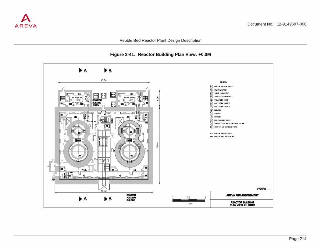
Document No.: 12-9149697-000
Pebble Bed Reactor Plant Design Description
Page 214
PROPRIETARY
Figure 3-41: Reactor Building Plan View: +0.0M

Document No.: 12-9149697-000
Pebble Bed Reactor Plant Design Description
Page 215
PROPRIETARY
Figure 3-42: Reactor Building Plan View: +12.7M

Document No.: 12-9149697-000
Pebble Bed Reactor Plant Design Description
Page 216
PROPRIETARY
Figure 3-43: Reactor Building Plan View: +25.4M

Document No.: 12-9149697-000
Pebble Bed Reactor Plant Design Description
Page 217
PROPRIETARY
Figure 3-44: Reactor Building Section A-A

Document No.: 12-9149697-000
Pebble Bed Reactor Plant Design Description
Page 218
PROPRIETARY
Figure 3-45: Reactor Building Section B-B

Document No.: 12-9149697-000
Pebble Bed Reactor Plant Design Description
Page 219
PROPRIETARY
Figure 3-46: Reactor Auxiliary Building Plan View: -6.5M

Document No.: 12-9149697-000
Pebble Bed Reactor Plant Design Description
Page 220
PROPRIETARY
Figure 3-47: Reactor Auxiliary Building Plan View: +0.0M

Document No.: 12-9149697-000
Pebble Bed Reactor Plant Design Description
Page 221
PROPRIETARY
Figure 3-48: Reactor Auxiliary Building Plan View: +7.0M

Document No.: 12-9149697-000
Pebble Bed Reactor Plant Design Description
Page 222
PROPRIETARY
Figure 3-49: Reactor Auxiliary Building Section A-A

Document No.: 12-9149697-000
Pebble Bed Reactor Plant Design Description
Page 223
PROPRIETARY
Figure 3-50: Turbine Building Plan View: +0.0M

Document No.: 12-9149697-000
Pebble Bed Reactor Plant Design Description
Page 224
PROPRIETARY
Figure 3-51: Turbine Building Plan View: +9.5M

Document No.: 12-9149697-000
Pebble Bed Reactor Plant Design Description
Page 225
PROPRIETARY
Figure 3-52: Turbine Building Section A-A
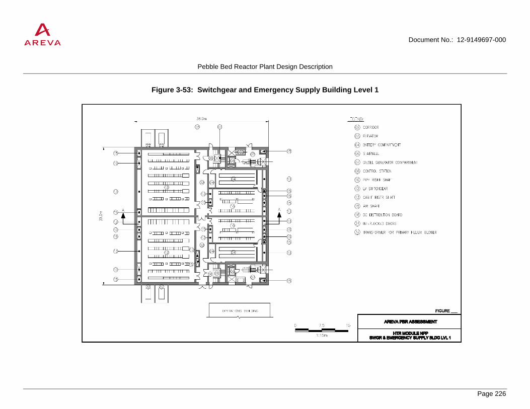
Document No.: 12-9149697-000
Pebble Bed Reactor Plant Design Description
Page 226
PROPRIETARY
Figure 3-53: Switchgear and Emergency Supply Building Level 1

Document No.: 12-9149697-000
Pebble Bed Reactor Plant Design Description
Page 227
PROPRIETARY
Figure 3-54: Switchgear and Emergency Supply Building Level 2

Document No.: 12-9149697-000
Pebble Bed Reactor Plant Design Description
Page 228
PROPRIETARY
Figure 3-55: Switchgear and Emergency Supply Building Section A-A
Document No.: 12-9149697-000
Pebble Bed Reactor Plant Design Description
Page 229
PROPRIETARY
Figure 3-56: Spent Fuel Storage Area Arrangement

Document No.: 12-9149697-000
Pebble Bed Reactor Plant Design Description
Page 230
PROPRIETARY
4.0 PLANT PERFORMANCE ASSESSMENT
This section details the plant performance in three critical areas:
• Steady state operation
• Plant transients
• Fuel performance
The steady state operation section provides a heat balance for the plant. The assessment shows that the plant will run at the projected level of efficiency and meet design requirements.
The plant transient performance assessment focuses on the response of the HTR-Module to different potential events applicable to high temperature gas-cooled reactors and more specifically the HTR-Module. Overall the assessment finds that the HTR-Module is capable of operating safely in all projected accidents and that the reactor will perform as necessary in all projected events and in all operating modes. The transient assessment includes a plant duty cycle.
The fuel performance assessment focuses on the development of TRISO particle fuel in Germany as part of the AVR and THTR projects. The current performance of UO2 fuel is shown to have very low fission product releases, even at accident level temperatures of approximately 1600°C, maintaining a high level of quality in manufacturing. This element is crucial for fuel design given heavy importance of fuel integrity in pebble bed reactor designs.
4.1 Steady-State Thermal Analysis
The purpose of the steady-state thermal design analysis is to develop a plant primary side heat balance, perform confirmatory calculations/estimates for the heat transfer and pressure drop data for the heat balance, and to consider the impact of design margins on plant performance. The full analysis is documented in Reference [6].
Figure 3-14 shows a cross-section of the reference plant primary side with the reactor on the left and the steam generator on the right attached via the cross-connect. Figure 4-1 shows the corresponding schematic of the reference plant and the primary state points along the primary flow path.
The primary fluid exits the cold gas duct at Point 1 at the primary inlet temperature of 250°C. Some heat loss through the Reactor Cavity Cooler System (RCCS) reduces the temperature of the primary fluid slightly at point 2 (entrance of the reactor vessel) The RCCS actually would remove heat through point 3, but the RCCS heat removal is all accounted for between Points 1 and 2. Then the helium rises up the cold gas columns to the inlet plenum at the top of the pebble bed reactor (Point 3). As it rises up, it is heated by the primary flow through the pebble bed and its temperature increases by 10°C. It passes through the reactor and is heated. A portion of the primary flow bypasses the reactor core. The helium actually enters the core at many locations (complex flow bypass) through the graphite block gaps. The effect of all of the bypass flow (net effect of all of the partial core bypass flow) is assumed to be 5% complete core bypass flow (represented by path 2a in Figure 4-1). The main core flow and the bypass flow mix at the reactor outlet and enters the hot gas duct (Point 4), at the design primary outlet temperature of 700°C. Through the hot gas duct assembly, some regenerative heat transfer between the hot and cold gas stream takes place, and the temperature of the hot fluid is decreased slightly before entering the steam generator (Point 5). The primary fluid passes through the steam generator, heating the secondary fluid

Document No.: 12-9149697-000
Pebble Bed Reactor Plant Design Description
Page 231
PROPRIETARY
(water), before exiting the steam generator (Point 6). The flow then enters the main circulator and is compressed back to the primary designed pressure of 6 MPa (Point 7).
Analytical inputs for heat transfer and pressure drops are identified in Table 4-1 and Table 4-2.
4.1.1 Design Operation vs. Expected Operation
Two heat balances are compared. The first heat balance, entitled design operation, is defined as when all design margins are used (pressure drop and steam generator heat transfer area). The expected operation heat balance uses no design margin. Design margins cover uncertainties – such as analytical and potential future design changes (unknown final design). Design margins considered are steam generator heat transfer surface area (15% margin: difference between installed and required surface area) and primary helium loop pressure drop (15% margin: 1.5 bar vs. 1.3 bar). The results of the two heat balances, using above heat transfer and pressure drop data along with appropriate margins, are illustrated below.
For each state point, the pressure and temperature are determined. The pressure is determined from pressure drop information. The temperature is determined from heat transfer data.
4.1.2 Design Point Heat Balance
All design pressure drop margin is used (total primary loop pressure drop of 1.5 bar) and all steam generator heat transfer surface area is needed. Table 4-3 summarizes the primary state points and the assignment of design conditions.
The results are summarized in a process diagram for the primary circuit of a single reactor/steam generator loop in Figure 4-2. The conditions shown in bold characters are the design conditions for the referenced plant.
The heat balance on the secondary (steam) side is shown in Figure 4-3, Figure 4-4, Figure 4-5, and Figure 4-6 based on an steam generator heat duty of 201.9 MWt from the primary side design point heat balance from Figure 4-2. The steam plant assumes two reactors, two steam generators, and two turbines, along with a single cooling tower and is operating during summer conditions. The steam plant is operating in cogeneration mode.
4.1.3 Expected Operating Point Heat Balance
The second heat balance, described below, shows the impact on steady-state plant performance when not all of the design margins are used. In this case, the primary helium loop pressure drop is 130.4 kPA (expected operating pressure drop) without the 15% margin added (as in the design point heat balance). Also, a 15% increase in steam generator heat transfer area is considered (i.e. there is 15% more steam generator tube bundle surface area than required to meet design conditions of reactor inlet/outlet temperatures of 250°C and 700°C, respectively).
The result of an increase in steam generator heat transfer surface area of 15% beyond required is a decrease in primary side helium temperature of about 8°C. Therefore reactor inlet and outlet temperatures would drop to approximately 242°C and 692°C, respectively, assuming mass flowrate remains at the design flowrate of 85.3 kg/sec (see Figure 4-2).
In reality, the plant control system would adjust the circulator speed (primary helium flowrate) to control the reactor outlet temperature to 700°C and let the reactor inlet temperature float. In this case, primary helium flowrate would be reduced about 2% from 85.3 kg/sec to 83.3 kg/sec. Reactor inlet temperature would adjust to about 239°C with reactor outlet temperature fixed at 700°C. Reactor power remains fixed at 200 MWt.

Document No.: 12-9149697-000
Pebble Bed Reactor Plant Design Description
Page 232
PROPRIETARY
Circulator power input requirements are reduced from 2.32 MWt to 1.83 MWt (2.57 MWe to 2.04 MWe) which slightly reduces steam generator heat duty from 201.9 MWt to 201.4 MWt.
Table 4-4 summarizes the primary state points and assignment of operating conditions. The corresponding expected point heat balance on the primary side, with adjustments made on helium flowrate (as described above) to control reactor outlet temperature to 700°C, is shown in Figure 4-7.
4.1.4 Comparison of Heat Balances
Figure 4-8 compares the steam generator temperature profile for both the design point (Figure 4-2) and expected point (Figure 4-7) heat balances. The horizontal axis in Figure 4-8 represents the three water/steam side sections of the steam generator. Point 3 to 2 on the horizontal axis represents the single phase region of feedwater heating up to saturation conditions, point 2 to 1 represents the constant temperature phase change from all liquid to all steam, and finally, point 1 to point 0 represents saturated to superheated steam conditions. The difference between the two heat balances for helium side steam generator temperatures is small (about 9°C to 10°C).
Table 4-5 compares electrical loads and output for the design point and expected operating point. The results in Table 4-5 for the design point are taken from steam plant heat balances. The expected point data in Table 4-5 were scaled from the design point numbers. The scaling used is as follows. For heat transfer related data (cooling tower), the scale factor used is the ratio of steam generator heat duty for expected point operation (201.4 MWt) divided by the design point steam generator heat duty (201.9 MWt), which equals 0.9975. The scale factor used for flow rate related data (pump losses) was the ratio of flow rates to the third power. The helium mass flowrate for the expected operation is 83.3 kg/sec while the design point flowrate is 85.3 kg/sec helium. The scale factor, therefore is (83.3/85.3)3 = 0.931. The third power is used because the pump power is proportional to flowrate x pressure drop of a loop. Loop pressure drop is proportional to flowrate squared, therefore pump power is proportional to mass flowrate to the third power. The above analysis assumes that the feedwater flowrate scales with steam generator heat duty (0.9975) so that steam conditions remain identical for expected operation and design point operation.
The expected operating point produces about 1.3 MWe more net electricity than the design case (110.6 MWe vs. 109.40 MWe). There is only a small difference in electrical output as is expected.
4.1.5 Conclusions
In conclusion, the impact of unused pressure drop margin and steam generator heat transfer margin have minimal impact on plant performance. The reactor inlet temperature would drop 11°C to 239°C and primary helium flowrate would drop about 2.3% from 85.3 kg/sec to 83.3 kg/sec. Steam generator heat duty would drop very slightly due to reduced primary helium circulator load from 201.9 MWt to 201.4 MWt.

Document No.: 12-9149697-000
Pebble Bed Reactor Plant Design Description
Page 233
PROPRIETARY
Table 4-1: Heat Transfer Input Data
Parameter Design Value
Description
RCCS heat load 400 kW Normal operation. For RHR mode, the design value is 850 kW
Regenerative heat in hot gas duct assembly
22.5 kW 5 kW/m x 4.5 m
Regenerative heat in cold gas columns
10°C Represents the temperature difference between Point 3 and Point 2
Steam generator regenerative heat 300 kW 0.15% of SG thermal power Steam generator heat loss to the ambient
10 kW 0.005% of steam generator thermal power

Document No.: 12-9149697-000
Pebble Bed Reactor Plant Design Description
Page 234
PROPRIETARY
Table 4-2: Pressure Drop Input Data
Pressure Drop Data
Reference Value
(without margin)
With 15% Margin)
Notes
Nominal Operating Pressure
6 MPa Table 3-9
Circulator total static head
1.3 bar 1.5 bar Table 3-15 (1.5 bar/1.15)
Pressure drop across core
0.68 bar @ 0.39 porosity
0.78 bar Section 3.2.2.3
Pressure drop across bottom reflector
0.13 bar 0.15 bar Section 3.2.2.3
Reactor Internals (inlet)
0.04 bar 0.046 bar Estimate
Pressure drop across top reflector
≈ 0 (negligible) ≈ 0 (negligible) Section 3.2.2.3
Steam generator pressure drop
0.44 bar 0.51 bar Calculated such that the total pressure drop is 130 kPa or 0.44 bar (without margin)
Cold gas duct 0.01 bar 0.011 bar Estimate Total: 1.3 bar 1.5 bar
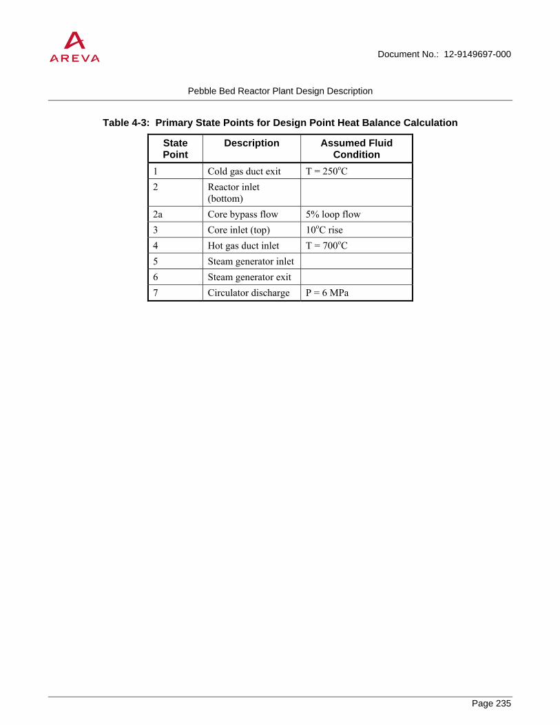
Document No.: 12-9149697-000
Pebble Bed Reactor Plant Design Description
Page 235
PROPRIETARY
Table 4-3: Primary State Points for Design Point Heat Balance Calculation
State Point
Description Assumed Fluid Condition
1 Cold gas duct exit T = 250oC 2 Reactor inlet
(bottom)
2a Core bypass flow 5% loop flow 3 Core inlet (top) 10oC rise 4 Hot gas duct inlet T = 700oC 5 Steam generator inlet 6 Steam generator exit 7 Circulator discharge P = 6 MPa

Document No.: 12-9149697-000
Pebble Bed Reactor Plant Design Description
Page 236
PROPRIETARY
Table 4-4: Primary State Points for Expected Point Heat Balance Calculation
State Point
Description Assumed Fluid Condition
2 Reactor inlet (bottom)
2a Core bypass flow 5% loop flow 3 Core inlet (top) 10oC rise 4 Hot gas duct inlet T = 700oC 5 Steam generator inlet 6 Steam generator exit 7 Circulator discharge P = 6 MPa

Document No.: 12-9149697-000
Pebble Bed Reactor Plant Design Description
Page 237
PROPRIETARY
Table 4-5: Comparison of Electrical Output and Loads for Design Point and Expected Operating Point
Design Point Heat Balance (two turbines/summer conditions) (from steam side heat balance)
Expected Point Heat Balance
(scaled from
Design Point Heat Balance)
ECP Loads Cooling tower 491 kWe 489.78 kWe Cooling water circ pump 459 kWe 427.47 kWe Condensate pump x 2 172 kWe 160.18 kWe HP Feedwater pump x 2 5,730 kWe 5,336.33 kWe Process feedwater pumps (3) 207 kWe 193 kWe
Total ECP loads 7,059 kWe 6,607 kWe ECP house loads 1,000 kWe 1,000 kWe BOP house loads 2,000 kWe 2,000 kWe Nuclear island house loads 2,000 kWe 2,000 kWe
Total Estimated house loads 5,000 kWe 5,000 kWe ECP Loads + house loads: 12,059
12.059 kWe MWe
11,607 11.607
kWe MWe
Main circulator x 2 5.14 MWe 4.08 MWe Total Electrical Loads 17.20 MWe 15.69 MWe Gross Electrical Power 126.6 MWe 126.2865 MWe Net Electrical Power 109.40 MWe 110.60 MWe HP Process Steam 22 kg/s @ 42 bar and 316 C 21.95 kg/sec
@ 42 bar and 316 C LP Process Steam 26 kg/sec @ 15 bar 248 C 25.94 kg/sec
@ 15 bar and 248 C
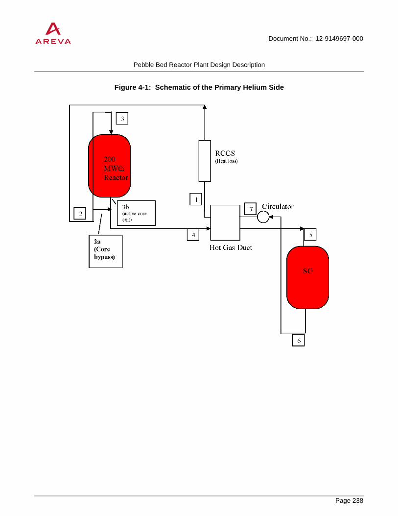
Document No.: 12-9149697-000
Pebble Bed Reactor Plant Design Description
Page 238
PROPRIETARY
Figure 4-1: Schematic of the Primary Helium Side

Document No.: 12-9149697-000
Pebble Bed Reactor Plant Design Description
Page 239
PROPRIETARY
Figure 4-2: Process Diagram for Primary Circuit at Design Point Operation

Document No.: 12-9149697-000
Pebble Bed Reactor Plant Design Description
Page 240
PROPRIETARY
Figure 4-3: Steam Plant Heat Balance for Design Point (Two Steam Generators)

Document No.: 12-9149697-000
Pebble Bed Reactor Plant Design Description
Page 241
PROPRIETARY
Figure 4-4: Steam Plant Heat Balance for Design Point (1st Turbine)

Document No.: 12-9149697-000
Pebble Bed Reactor Plant Design Description
Page 242
PROPRIETARY
Figure 4-5: Steam Plant Heat Balance for Design Point (2nd Turbine)

Document No.: 12-9149697-000
Pebble Bed Reactor Plant Design Description
Page 243
PROPRIETARY
Figure 4-6: Steam Plant Heat Balance for Design Point (Reboilers)

Document No.: 12-9149697-000
Pebble Bed Reactor Plant Design Description
Page 244
PROPRIETARY
Figure 4-7: Process Diagram for Reference Plant Primary Circuit at Expected Operating Point (without design margins)

Document No.: 12-9149697-000
Pebble Bed Reactor Plant Design Description
Page 245
PROPRIETARY
Figure 4-8: Comparison of Steam Generator Temperatures

Document No.: 12-9149697-000
Pebble Bed Reactor Plant Design Description
Page 246
PROPRIETARY
4.2 Plant Transient Evaluations
This section evaluates the control logic and response to the different transients that may occur throughout the operating life of the HTR-Module. It also presents a representative plant duty cycle for pebble bed reactors.
4.2.1 General Safety Considerations of the HTR-Module
The HTR-Module includes the typical beneficial design features of a gas/graphite system. Moreover, the HTR-Module is designed for continuous refueling, which results in only a small portion of excess reactivity. Therefore, the core can be shutdown using only the reactor shutdown rods, which are activated by the reactor protection system any time an abnormal condition is detected and will fall under gravity if power is lost. A second, manual system (small shutdown balls) is included that, in combination with the shutdown rods, can maintain the reactor in cold shutdown condition. The third way to shutdown the reactor is to turn off the main circulator. This results in a rise in core temperature causing it to go subcritical and shutdown due to a negative temperature coefficient.
The core power density and geometry are designed so that the maximum fuel temperature will be approximately 1600°C even in a worst-case accident when no active heat removal systems for the core are operating. The fuel elements are manufactured to high standards in order to maintain a low failure rate and retain almost all fission products even at the maximum temperature.
The core has a large thermal inertia and will heat slowly during an accident, which makes it possible to make repairs to the system and restore active heat removal before the peak fuel temperature is reached. If repairs cannot be made quickly, then the long, narrow design for the core allows for the maximum amount of passive heat removal in order to ensure that the peak fuel temperature does not exceed approximately 1600°C. The core height is also chosen in order to prevent undamped axial xenon oscillations. Overall, the HTR-Module relies on passive safety systems that either operate continuously, as in the case of the cavity cooler, or are automatically activated when accident conditions exist, as in the case of the shutdown rods.
4.2.2 Categories of Transients and System Response
The categories of transients follow the different service level categories similar to those of the ASME BPVC shown in Table 4-6. In general, Service Level A events will occur between hundreds and hundreds of thousands of times during the life of the plant. Service Level B events such as reactor trips can be expected to occur hundreds of times. Service Level C events, such as Loss of Coolant Accident (LOCA) or secondary system breaks, can be expected to occur only a few times over the life of the plant. The reactor is designed to be able to experience Service Level D events one time and still shutdown in a safe manner. A summary of events and approximate number of cycles for each service level can be found in Table 4-7. This duty cycle is essentially what was used in the design of the HTR-Module. The duty cycle estimates are based upon a 40 year plant life with 80% availability. Reactivity events, depressurization events, and loss-of-forced-cooling events will fall, depending on their frequency, into Section Level B, C, or D. Some types of events may fit more than one category at the same time.
During normal operation, the reactor systems will be used to heat up and start the reactor, or cooldown and shutdown the reactor. During power generation modes, the high thermal inertia of the reactor can be utilized to smooth out any short-term perturbations in total demand for either electricity or process heat; these are all Service Level A events.

Document No.: 12-9149697-000
Pebble Bed Reactor Plant Design Description
Page 247
PROPRIETARY
During Service Level B, C, and D events, the HTR-Module systems are primarily used to keep the radiological impacts below the allowable limits and to reduce the component and system loadings. If any of the following reactor protection initiation criteria are met, the reactor will scram:
• Thermally-corrected neutron flux greater than or equal to 120%
• Hot gas temperature greater than or equal to 750°C
• Cold gas temperature greater than or equal to approximately 280°C
• Negative variable limit for thermally-corrected neutron flux greater than or equal to 20% per minute
• Period less than or equal to approximately 20 seconds
• Intermediate-range neutron flux greater than or equal to maximum and release for power range not given
• Mass flow ratio (primary to secondary side) greater than or equal to 1.3 or less than or equal to 0.75
• Moisture in the primary side greater than or equal to approximately 800 ppmv
Reactor scram is initiated once the reactor protection limits have been reached. The system takes the following actions, regardless of the initiating event, for a reactor scram:
• The main circulator trips
• The reflector (control) rods drop
• The steam generator is isolated
In addition to these first three actions the following take place during specific event categories:
• During a depressurization event the primary system is isolated upon activity detection in the reactor building or water detection in the coolant.
• During a tube break event the steam generator relief (dump) valve opening is initiated
After the reactor is shutdown, it can be re-started from a hot condition for up to an hour. After an hour the xenon build-up prevents a hot startup and requires a cooldown of at least 24 hours before the reactor can restart.
4.2.2.1 Normal Operation
The HTR-Module is intended to provide electrical power generation, process heat or a combination of both. It is designed to operate in a range of 50 to 100 percent of power and the reflector rod worth is sufficient to shutdown the reactor in this power range. The Level A transients cover startup, shutdown, power operation, and load following capability.
Cold startup of the reactor is accomplished by:
• Charging the primary loop with helium from the helium purification system;

Document No.: 12-9149697-000
Pebble Bed Reactor Plant Design Description
Page 248
PROPRIETARY
• Activating the main circulator;
• Withdrawing reflector rods and taking the reactor critical;
• Beginning primary loop heatup at 2K/minute using the startup/shutdown circuit until steaming is initiated in the secondary loop; and
• Continuing heatup with the main loop until full power is achieved in 6 to 8 hours.
Once the startup process is complete (reactor at a minimum of 50 percent power), then electricity generation, process heat generation or cogeneration can begin. Any transfers between combined process heat and electrical output in cogeneration mode to the electricity-only mode or process heat-only mode is accomplished by operating the appropriate valves within the secondary and tertiary loops. The transition has no impact on the HTR-Module primary loop assuming the HTR-Module is operating at 100% power. The high thermal inertia of the reactor can be utilized to smooth out any short-term perturbations in total demand caused by the switch-over. All changes in total load are accommodated by first increasing or decreasing the feedwater flow and then adjusting the main circulator speed accordingly. If the plant is already operating at 100% power in cogeneration mode, an increase in the process heat demand can also be accommodated by running back the electrical output, or vice-versa; in either case there is no impact on the primary loop.
Cold shutdown of the HTR-Module is accomplished as follows:
• Runback reactor power to 20% by reducing primary coolant flow;
• Decrease core outlet temperature to 550°C at 2K/min using the reflector rods;
• Bring on the startup and shutdown circuit and continue cooldown at 2K/min with the feedwater at 20% until there is only water on the secondary side of the steam generator;
• Fully insert the reflector rods to shut down the reactor and continue cooldown using the primary heat transfer system;
• Depressurize the primary system once cold conditions have been achieved by discharging the helium inventory to the helium purification system.
The shutdown ball elements along with the reflector rods are required to maintain the reactor in a subcritical state at cold conditions.
4.2.2.2 Reactivity Events
Several events can change the reactivity of the core, including: inadvertent reflector rod or small shutdown ball movements, sudden over- or under-cooling of the core, water ingress and seismic events. The severity of the increase or decrease in the reactivity for uncontrolled movement of the reflector rods depends on the initial condition of the core (cold startup, full power, etc.) and the rate of the change of the reflector rod position.
Changes in feedwater flow to the steam generator or in the speed of the main circulator result in sudden over- or under-cooling of the core, which will increase or decrease reactivity. The reactor protection system will trigger a scram when it detects changes in the mass flow ratio or the gas temperature.
Document No.: 12-9149697-000
Pebble Bed Reactor Plant Design Description
Page 249
PROPRIETARY
Water ingress into the system can happen due to leakage from the steam generator tubes. In the worst-case scenario evaluated in the HTR-Module safety analysis, the peak local corrosion is approximately 3.3%. Since more than 40% corrosion is required to erode the unfueled graphite outer shell of the fuel elements, their integrity as fission product retention barriers is not significantly degraded (and the integrity of the fuel particles within the fuel elements is not impacted in any case).
During a seismic event, the pebble bed can compact. A compacted bed will have reduced neutron leakage and the upper surface will move downward relative to the reflector rods. If the reactivity increases due to these changes are small, compensation via reflector rod position adjustments and/or circulator speed adjustments will restore the previous operating condition.
For all of these events, reactor scram is initiated once the reactor protections limits are reached. As a result, the reflector rods drop into the lowest position, the main circulator is tripped and the steam generator is isolated on the feedwater and steam side. These actions safely render the plant subcritical. In addition to these measures, when moisture is detected in the primary loop, the pressure in the steam generator is relieved until the pressure is less than the primary side in order to limit the amount of water inserted into the core. Prior to re-start, the steam generator and primary system will be processed by the helium purification system to condense out the water.
It is possible that during a minor earthquake none of the initiating criteria will be met for a reactor trip. Analysis of this case showed that the maximum temperature for the fuel would fall within the operating experience for the fuel. For all the reactivity events analyzed, the fuel elements and components did not experience unacceptable loadings. Inadvertent withdrawal of the reflector rods is the bounding accident for reactivity events. The worst case condition is withdrawal of all rods when the reactor is at full load after a return to full power from a part load condition. In this case, the fuel temperature can rise to approximately 950°C before the reactor protection limits are reached and the reactor scrams. This temperature is well below the temperatures that will lead to significant failures in the fuel elements.
4.2.2.3 Depressurization Events
System depressurization events can occur due to breaks in a system connected to the pressure vessel unit or inadvertent opening of a safety valve in the pressure relief system. The break may be large or small. For a small break some helium will continue to circulate and cool the core resulting in a slightly lower peak fuel temperature than when a large break in the primary loop occurs. The reactor will scram once the reactor protection limits are reached, and in addition to normal actions taken by the reactor protection system (RPS), the primary system will be isolated due to an increase in activity in the reactor building and the sub-atmospheric pressure system will be actuated.
For a large break in the primary coolant system, convection processes in the reactor core will be of no significance and heat will be removed by the cavity cooler through conduction out of the core. The peak core temperature of approximately 1600°C is reached after about 30 hours, a peak core barrel temperature of 490°C is reached, and the peak vessel temperature does not exceed 350°C. Any fission products in the coolant will be released into the building during depressurization and from there into the environment as long as the building pressure exceeds the 0.1 bar pressure relief port set point. The fuel elements will not have significant failures at the maximum temperature and will retain the majority of the fission products. Less than 1% of the fuel elements will reach a temperature in excess of 1500°C and will remain at this temperature for no more than 20 hours.

Document No.: 12-9149697-000
Pebble Bed Reactor Plant Design Description
Page 250
PROPRIETARY
4.2.2.4 Loss of active cooling events
Transients that involve the loss of active cooling for the HTR-Module can include events involving leaks in the system that result in depressurization or water ingress in the reactor core, which are discussed in previous sections. This section discusses the system response when there are no breaks in the system and the primary loop remains pressurized.
The type of event that occurs will determine which accident initiation criteria will trigger a reactor scram. For example, loss of auxiliary power leads to failure of the main circulator and feedwater pumps. The reactor protection system will detect either a mass flow ratio greater than or equal to 1.3 or a negative variable limit for thermally corrected neutron flux greater than or equal to 20%/minute. In all cases, the reactor will trip and will experience a pressurized cooldown.
For a pressurized cooldown, assuming the circulator damper closes, natural circulation will be established within the reactor vessel. The core internal temperatures redistribute accordingly and start to rise. Excess heat is radiated through the vessel to the cavity coolers which run all the time. The maximum temperature on the core centerline at the top reaches 1130°C in about 6 hours and then begins to decline. The maximum vessel temperature is 320°C (at 75 hours). The maximum core barrel temperature is 400°C. The peak load on the cavity coolers is 815 KW. This scenario is bounded by the depressurized cooldown. The peak fuel temperature is well below the level where failure occurs. The design limits of 500°C for the core barrel and 350°C for the reactor pressure vessel are not exceeded (Ref. [7]), so it can be concluded that the thermal load on relevant components are in an acceptable and reasonable range.
4.2.2.5 Other Events for Consideration
Other events have been identified through reviews of high temperature reactor plant duty cycles and are recommended for inclusion in the final duty cycle. Many of these events are implicitly included in Table 4-7 but should be explicitly addressed in the plant duty cycle. These events include:
• Transition between full electrical mode to full process heat mode to cogeneration mode
• Reactor trips at power less than 100%
• Load rejection in any operating mode
• Events related to turbine and condenser malfunction
• Loss of onsite or offsite power and combination with other events
• Earthquake other than the safe shutdown earthquake
4.2.3 Summary / Assessment
The HTR-Module design provides controls to meet requirements for normal operation and accident conditions without exceeding design limits. The HTR-Module is designed to respond to the demands of various normaland off-normal operating transients that can be expected during the life of the plant. When necessary, the reactor will response automatically to design basis events and safely shutdown the reactor to prevent excess loads on the system and radiological releases to the environment. Further discussion of plant operations and the plant response to safety events is provided in the scoping safety study.

Document No.: 12-9149697-000
Pebble Bed Reactor Plant Design Description
Page 251
PROPRIETARY
Table 4-6: Service Levels (per ASME BPVC, Section III)
Service Level ASME B&PV Code Descriptions
A Loadings arising from system startup, operation in the design power range, hot standby, and system shutdown.
B
Events that are anticipated to occur often enough that design should include a capability to withstand them without operational impairment. These events include any abnormal incidents not resulting in a forced outage and also forced outages for which the corrective action does not include any repair of mechanical damage.
C
Events that require shutdown for correction of the loadings or repair of damage in the system. These conditions have a low probability of occurrence, but are included to provide assurance that no gross loss of structural integrity will result as a concomitant effect of any damage developed in the system.
D Combinations of loadings associated with extremely low probability, postulated events whose consequences are such that the integrity and operability of the nuclear energy system may be impaired to the extent that only considerations of public health and safety are involved.

Document No.: 12-9149697-000
Pebble Bed Reactor Plant Design Description
Page 252
PROPRIETARY
Table 4-7: Plant Duty Cycle Summary
Service Level
Total Number Of
Occurrences
Events
Startup out of plant condition zero load cold Startup out of plant condition hot zero power Shut-down into plant condition zero load cold out of nominal operation Shut-down into plant condition hot zero power out of nominal operation Max. power change: ± 50% with load change velocity: 5%/min Max. power change: ± 20% with load change velocity:10%/min Max. power change: ± 5% with maximum load change velocity of 1%/s
A 70,400 +
Unlimited power changes of ±1% at 1%/s Reactor trip (Scram) Hot standby up to 1 h after Scram (pressurized loss of coolant) Hot standby up to 24 h after Scram (pressurized loss of coolant) Hot startup after Scram Shut-down after Scram in hot zero power Restart after Scram out of hot zero power Emergency power case (Duration ≤ 1 h) Failure of primary mass flow Failure of feed water mass flow Small absorber ball column drop False closure of a main steam isolation valve Increase or decrease of main circulator due to control error Run up Increase or decrease of feed water mass flow due to control error Continuing operation with an incorrectly inserted reflector rod Reduced main steam removal Increased main steam removal Continuing reactor operation during failure of a cavity cooler train (secured train) Failure of the nuclear cavity cooling system (operational train) Hot standby > 24 h (pressurized loss of coolant) Targeted pressure relief for repairs in the primary circuit Failure of feedwater heating Excessive feedwater heating due to control error
B 2000
Inadvertent closure of a main steam valve during operation with only one Module Steam generator tube bundle leakage with response of the steam generator pressure relief Safe shutdown earthquake (SSE) Long-term emergency power case with unavailable emergency power system
C 11
Complete pressure relief of the primary circuit with subsequent shutdown to cold

Document No.: 12-9149697-000
Pebble Bed Reactor Plant Design Description
Page 253
PROPRIETARY
Service Level
Total Number Of
Occurrences
Events
condition Rupture of a DN 65 connection pipe directly on the pressure vessel unit with subsequent core heat up Main steam pipe break Feed water pipe break Airplane crash
D 5
Explosion blast wave

Document No.: 12-9149697-000
Pebble Bed Reactor Plant Design Description
Page 254
PROPRIETARY
4.3 Fuel Performance Assessment
This section summarizes the experience of the UO2 pebble bed fuel design in Germany with an emphasis on its performance in retaining fission products and consistent manufacturing of the TRISO particle. This assessment is based solely on UO2 fuel. The technology readiness report addresses the use of UCO fuel.
4.3.1 Introduction
The German High Temperature Reactor Fuel Development Program successfully developed, licensed and manufactured many thousands of spherical fuel elements that were used to power the experimental AVR reactor and the commercial THTR reactor. In the 1970s, this program extended the performance envelope of HTGR fuels by developing and qualifying the TRISO-coated particle system. Irradiation testing in real-time AVR tests and accelerated MTR tests demonstrated the superior manufacturing process of this fuel and its irradiation performance.
In the 1980s, another program direction change was made to a low enriched (LEU) UO2 TRISO-coated particle system coupled with high-quality manufacturing specifications designed to meet new HTGR plant design needs. These needs included requirements for inherent safety characteristics under normal operation and all design-basis accident conditions. The German fuel development program was able to qualify and license the LEU UO2 TRISO fuel system for all modern HTGR designs.
4.3.2 TRISO Particle Design and Function
The primary function of the TRISO coating is to retain the fission products produced within the fuel kernels. As discussed in Section 3.1.2.1, the fuel particle is the primary barrier against releases of radioactivity.
For the HTR-Module, each TRISO coated particle is a miniature spherical ceramic UO2 fuel material protected by four successive ceramic coating layers that perform specific design functions. TRISO particle designs were continuously refined throughout the 1980s and 1990s to develop what is generally accepted as the modern or reference design for the HTR-Module. The design characteristics for the reference fuel element are shown in Table 4-8.
The fuel kernel, at the center of the TRISO fuel particle, is the primary power source for the HTR-Module and produces almost all of the fission products. The fuel kernel also serves as a significant barrier to radionuclide release by immobilizing many of the fission products as stable oxide compounds and delaying the diffusive release of others, allowing them to decay into more stable isotopes. These processes substantially reduce fission product release from particles.
The buffer layer bonds to the fuel kernel and is a low-density, porous carbonaceous layer. The buffer layer provides void volume for the accumulation of gaseous fission products released from the fuel kernel, accommodates fuel kernel swelling, and serves as a sacrificial layer for fission fragments.
The inner pyrocarbon (iPyC) layer, between the buffer and SiC layer, is a gas-tight coating that protects the kernel from hot gaseous chlorine compounds during SiC decomposition and provides a smooth substrate for SiC deposition. The iPyC retains fission gases xenon, krypton, and iodine completely and also serves as a diffusion barrier to metallic fission products. During irradiation this layer shrinks and the contraction helps to reduce tensile stresses on the SiC.

Document No.: 12-9149697-000
Pebble Bed Reactor Plant Design Description
Page 255
PROPRIETARY
The third layer is a near-theoretical density SiC layer which serves as the pressure bearing component of the particle and the primary metallic fission product diffusion barrier as well as retains all gaseous fission products. The SiC layer is the primary load bearing layer of the particle.
The fourth and outer layer is another high-density, isotropic layer, called the outer pyrocarbon (oPyC). This layer serves as a further diffusion barrier for gaseous and metallic fission products, and like the iPyC layer, it too contracts during irradiation helping to reduce tensile stress on the SiC. The oPyC also protects the SiC during particle handling and sphere/compact formation and provides a bonding surface to the carbon matrix in the fuel element.
The fuel element (FE) for the HTR-Module is a 60 mm diameter sphere consisting of a spherical fuel zone of approximately 50 mm diameter, in which the TRISO-coated particles are randomly distributed in the graphitic matrix material. A fuel-free shell of graphite matrix of about 5 mm in thickness is then molded to the fuel zone. The matrix material consists of a carbonized organic binder and nuclear-grade graphite material that acts as a fission neutron moderator, heat transfer medium, and protection against external forces. The graphitic matrix material exhibits high density, high thermal conductivity, high mechanical strength, low thermal expansion, low anisotropy, low Young’s modulus, good corrosion resistance, good dimensional stability under neutron irradiation, and a very low concentration of impurities.
4.3.3 Fuel Quality and Performance
As mentioned before fuel quality is extremely important for the safety of the HTR-Module. For this reason a major effort was carried out to test varying types of fuel in the AVR and THTR reactors in the 1980’s. The most important layer in TRISO particle fuel is the SiC layer because it is the primary fission product boundary. In order to test for manufacturing defects, a burn-leach test using nitric acid is performed to test for deficiencies in the SiC layer. The SiC layer will normally withstand the attack, but if an area of the kernel is exposed the uranium will be leached out into the nitric acid. From the quantity of uranium in the solution an analysis can be performed to determine the amount of defective fuel particles. Two eras of testing took place, before 1985 and after. Since the post-1985 manufacturing process is more representative of the reference fuel design for the HTR-Module, the post 1985 data is presented in Table 4-9 and is a good benchmark for the effectiveness of the manufacturing capabilities.
In order to adequately assess the fuel particle integrity under operating and accident conditions several tests and analyses of the fuel were done at various temperatures and fluence levels. For MTR testing a total of 9 TRISO particles failed out of 240,452 particles irradiated. These 9 particles were non-reference fuel elements. Of the 159,880 reference fuel particles irradiated zero particles failed, giving a failure fraction of ≤ 1.87 x 10⁻⁵ at the upper 95% confidence limit. For elements irradiated in the AVR, 240 of the high performing reference fuel elements were collected and measured for 85Kr release and fuel failure. The release data showed that, with a few exceptions, the release fraction of 85Kr was < 10-6 at a temperature range of 1250°C to well beyond 1400°C. Of the 393,600 TRISO fuel particles analyzed, there were zero failures, producing a ≤7.6 x 10⁻⁶ failure fraction with a 95% confidence level.
The KÜFA tests conducted in Jülich from 1985-1995 and in Karlsruhe from 2005-2010 demonstrated the fuels capability to operate at accident temperatures. During these tests there was no particle failure nor any noticeable cesium or strontium release during the first few hundred hours of operation at 1600°C. This temperature is close to the maximum achieved in the HTR-Module in accident conditions and shows high fuel integrity even at the postulated worst-case accident temperatures. It was shown that at 1700°C only one failure occurred. Above this temperature multiple failures occurred. From these high temperature tests it was observed that krypton is always

Document No.: 12-9149697-000
Pebble Bed Reactor Plant Design Description
Page 256
PROPRIETARY
released later than cesium, due to the additional retention provided by the dense intact pyrocarbon layers. However, if these layers are not intact then krypton is released as readily as cesium.
The KÜFA tests showed that if the maximum burnup in the UO2 fuel element is kept strictly below 11% fissions per initial heavy metal atom (FIMA), as is typical with the HTR-Module design, the allowable fuel temperature limit may be higher than 1600°C. If the burnup of UO2 TRISO-coated particle fuel is pushed to 15% FIMA, fuel temperature must be rigorously limited to ≤ 1600°C.
There were a multitude of tests conducted on the fuel pebbles during the time frame from 1981 until 2010. All tests conducted during this time period, not excluding failed designs or past designs no longer quantifiable under the reference fuel particle, are combined to show the overall performance of the German High Temperature Reactor Fuel Development Program and is presented in Table 4-10. This is a conservative estimate for the fuel failure rate because it encompasses lower quality non-reference fuel. As discussed previously, the fuel manufacturing process has been redefined multiple times and significantly improved since its introduction. With that being said, Table 4-10 shows that the fuel failure is at or below the NGNP requirements of 4.6 x 10⁻⁵ with a 95% confidence level for normal operation and well below 5.0 x 10⁻⁴ with a 95% confidence level for accident conditions.
Figure 3-3 presents the limiting fuel failure rates used as the HTR-Module design basis. Additional statistical modeling of fuel failure rates due to irradiation have been completed since this curve was produced based on the tests described above. These models have shown a decrease in the failure rate of the fuel compared to the HTR-Module design basis. It is safe to assume, then, that the HTR-Module design basis is conservative and lower fuel failure rates can be expected..

Document No.: 12-9149697-000
Pebble Bed Reactor Plant Design Description
Page 257
PROPRIETARY
Table 4-8: HTR-Module Reference Design
Component Material Dimensions (µm) Density (Mg/m3) as fabricated
Fuel Kernel Uranium Dioxide (UO2) Diameter: 500 ≥ 10.4 Buffer Layer Porous PyC Thickness: 95 1.0 Inner PyC Layer Dense PyC Thickness: 40 ≥ 1.85 Fission Product Barrier Dense SiC Thickness: 35 ≥ 3.2 Outer PyC Layer Dense PyC Thickness: 40 1.85

Document No.: 12-9149697-000
Pebble Bed Reactor Plant Design Description
Page 258
PROPRIETARY
Table 4-9: Manufacturing Failure Statistics for Post-1985 TRISO Coated Fuel
Defective / Failed Particle Fraction
Fuel Element
Type Year Particles
per FE FEs
Tested Particles
Tested (N)Defects
Found (n) expect d=(n/N)
Upper 95%
AVR 21-2 1985 9560 40 382400 3 8 x 10⁻⁶ 2.0 x 10⁻⁵
Module Proof Test 1988 14600 10 146000 3 2.1 x 10⁻⁵ 5.3 x 10⁻⁵

Document No.: 12-9149697-000
Pebble Bed Reactor Plant Design Description
Page 259
PROPRIETARY
Table 4-10: Fuel Performance of All Fuel Tested under the German HTGR Fuel Development Program
No. of Fuel Bodies
No. Coated Particles (N)
No. Failed Particles (n)
Failure Fraction, 95% Confidence Limit
Manufacture 175 2,202,200 86 4.67 x 10⁻⁵
Irradiation Testing 88 751,124 9 2.09 x 10⁻⁵
Accident 19 287,480 5 3.66 x 10⁻⁵

Document No.: 12-9149697-000
Pebble Bed Reactor Plant Design Description
Page 260
PROPRIETARY
5.0 NGNP DESIGN REQUIREMENTS
Design requirements applicable to the NGNP program are identified in References [8] and [9]. The HTR-Module design was not governed by these design requirements. However, a review of the NGNP requirements was performed and the HTR-Module was assessed against the relevant NGNP requirements (Ref. [10]). The requirements review identified requirements that were particularly relevant to PBR designs and that were useful in assessing the design’s suitability for the NGNP program. Additional requirements were considered beyond what is specified in the NGNP requirements documents. The results of the assessment are presented in the PBR Technology Readiness Assessment Report.
The following key PBR requirements were identified:
• Must have a heat source based on the HTGR concept.
• Must use forced circulation helium as the heat transport fluid.
• Must have a plant design lifetime of 60 years.
• Must meet NRC regulations (as agreed upon for HTGR technology).
• Must be designed such that it can be design certified for a broad range of applications and sites.
• Must meet all applicable federal, state and local codes and standards.
• Must support complete design, licensing, construction and startup testing for initial operation by 2021 (per EPAct 2005).
• Must supply high temperature steam.
• Must be applicable to a broad range of cogeneration application supplying, singly or in combination, electricity, steam, and hot gas.
• Must have a reactor gas outlet temperature in the range of 750ºC to 800ºC.
• Must support process steam, electricity, and cogeneration.
• Must be able to distribute electricity on the commercial grid.
• Must be capable of co-location with process heat users.
• Must be economically competitive with long-term fossil fuel prices.
• Must have passive decay heat removal to cool the core from full power to safe shutdown conditions.
• Must be safe for plant personal, general population, and the environment.

Document No.: 12-9149697-000
Pebble Bed Reactor Plant Design Description
Page 261
PROPRIETARY
6.0 POTENTIAL DESIGN ADVANCEMENTS
The PBR concept description in Section 3.0 is based on the HTR-Module design. If pebble bed reactor technology were pursued for the NGNP program, modifications to the design concept would be expected. This section identifies and recommends a number of potential advancements to the HTR-Module design for consideration in later design stages.
The purpose of this section is not to provide a comprehensive list of proposed modifications to the design. Design modifications that would be expected as part of the normal design process are generally not identified here. For instance, upgrades to the instrumentation and control systems are not identified, even though it would be expected that the I&C systems for NGNP would use modern equipment. In general, it is assumed that the design process would apply the current state of the art. The potential advancements listed in this section focus on design modifications that reflect changes in major design requirements or that have interesting implications worth discussing in a technology assessment.
The potential advancements listed here are separated into two categories: near-term and long-term. Near-term advancements should be considered for the first generation of PBR plants developed through the NGNP project, though not necessarily the first-of-a-kind plant. Long-term advancements may be considered in future generations of PBR plants and are included in this report to highlight the capability of the technology.
6.1 Near-Term Advancements
The following near-term advancements should be considered for the first generation of PBR plants developed through the NGNP project.
6.1.1 Increase Reactor Power from 200 MWt to 250 MWt
6.1.1.1 Objective
This assessment will focus on the considerations, methods, and effects of increasing the reactor power for the HTR-Module from 200 MWt to 250 MWt. The main purpose for this increase is to improve the economics of the plant. An increase in power has the potential to reduce the $/kWh for the reactor. The following design constraint must be observed before the assessment can be done. The fuel must operate within the range of its current expected qualified design envelope. Thus the amount of uranium within the fuel particle will stay the same due to excess cost for qualification of a new fuel particle. The most logical ways to increase the core power without major fuel design would be to either increase the core volume or increase the core power density. Finding a balance between these two parameters will need to be reached when optimizing the design. The main issues of concern from an increase in power include fuel handling capacity, post accident heat removal, maintaining safe shutdown margin, fuel operating temperatures, and steam generator and circulator design.
6.1.1.2 Considerations
The ability to passively remove core residual heat is a feature of the HTR-Module that must be maintained and needs to be addressed when considering an increase in core power output. An increase in thermal power will increase the amount of residual heat that would need to be removed from the core. The amount of heat that must be removed from the core in the passive form of the RHRS limits the core diameter to approximately 3 m. The cavity cooling system, under normal and accident conditions, must be able to remove enough heat from the core so as to not compromise the safety limits of the reactor components. This not only includes the maximum fuel
Document No.: 12-9149697-000
Pebble Bed Reactor Plant Design Description
Page 262
PROPRIETARY
temperature, but also the temperatures of the core internals, structure, supports, nozzles, and the concrete that surrounds the core. These structures all aid in passively storing heat that must be removed by the cavity cooling system. Their material safety limits will need to be analyzed in addition to their heat removal capacities when analyzing the capacity of the cavity cooling system during normal and passive heat removal of the 250 MWt core.
Passive heat removal has not been shown to be a risk for other designs of 250MWt pebble bed cores, and does not pose a significant risk in the feasibility of a power increase.
The HTR-Module has eliminated control rods or shutdown units that penetrate the active core. For this reason shutdown units are inserted around the parameter of the reactor and active core radius is critical for the maintaining enough margin to shut down the reactor. Maintaining a safe shutdown margin, using shutdown units inserted into the parameter of the core, limits the core diameter to 3 m. For this reason, in order to increase the core volume, the core height will need to be increased.
6.1.1.3 Increasing Reactor Power
The core operational margins allow for some power increase due to the significant amount of margin that was built into the original design. In particular, new computation capabilities would allow reducing some design margin to relax certain limits.
Two possibilities are considered here to increase the overall core power:
• Increasing the core power density (power per pebble)
• Increasing the core volume
Power increase can be achieved with an increase in thermal conductivity (heat transfer coefficient) of the fuel element matrix. This would lead to a power increase of approximately 10% in each fuel element and hence to the same increase in the core power density.
Independently, it is also possible to increase reactor power with an increase in the core volume. The core radius is limited to 3 m due to limitations of shutdown margin and passive heat removal. Increasing the core height, however, has no significant impact on manufacturability, shutdown margin, or peak fuel temperature. A large increase in core height will require an analysis of the xenon concentration to ensure that appropriate dampening occurs under all operating conditions.
The HTR-Module is designed to operate between 50% - 100% thermal power when in equilibrium. In addition the core must be able to make power swings from 100% - 50% - 100% in accordance with the plant duty cycle requirements. During these power swings the main concern is xenon build up and burnout and the effect of dampened peak and burnout oscillations of xenon on the local power density. If during a power swing a de-pressurization accident occurs, which is the most limiting accident for the HTR-Module, it must be shown that the peak fuel temperature is acceptable during the decay heat removal following this specific accident.
An increase in core volume would increase the amount of fuel within the core without increasing the core power density, thus increases in fuel temperatures would be negligible. The Chinese pebble bed design (HTR-PM) increased the core height to 11 m and was able to maintain a core power density close to that of the HTR-Module.
Consequently, increasing the power from 200 MWt to 250 MWt implies the number of fresh fuel elements added each day should be increased from 360 to 450. This also implies increasing the amount of fuel elements being

Document No.: 12-9149697-000
Pebble Bed Reactor Plant Design Description
Page 263
PROPRIETARY
circulated by the fuel handling system each day from 5360 to 5450. This does not represent a significant increase in the circulation rate regarding potential feasibility issues (see the discussion of on-line refueling in the technology readiness assessment report).
Increasing the core power would lead either to an increase in the mass flow of the helium coolant or to an increase in the temperature gain across the core. One approach would be to keep the temperature gain across the core relatively constant and operate the fuel within the current qualification range. Increasing the mass flow rate to satisfy this condition would lead to an increase from 85 kg/s to approximately 106 kg/s. An increase in the mass flow would lead to an increase in the load of the main circulator. This would impact the qualification and design effort of a single circulator that could produce 106 kg/s of helium, while maintaining its physical size constraints and operating parameters.
There are two possibilities to limit the required main circulator driving force increase:
• Increasing the primary circuit pressure
• Increasing the helium temperature rise through the core
An increase in mass flow rate will increase the required driving power of the main circulator to circulate more coolant through the pebble bed core. This driving power being proportional to the volumetric flow rate (not the mass flow rate), this increase may be limited by increasing the primary circuit pressure, taking advantage of existing design margins. In this case, it would be essential to analyze the impacts on the pressure vessel unit design for this increase in system pressure. Any component changes based upon this pressure increase will need to be assessed. Even a small increase in mass flow rate would produce a large increase in the circulator power.
In addition, the potential of increasing the core outlet temperature up to 750°C may be investigated as a solution to limit the increase of the main circulator driving power.
For example, the current main circulator power is approximately 3 MWe. An increase of 25% reactor power would lead to a main circulator power increase up to about 4.4 MWe with increasing the primary pressure from 60 bar to 70 bar and also increasing the core outlet temperature to 750°C. A main circulator design above 4 MWe would lead to a significant increase in cost for research and design.
An alternative to increasing the size of the circulator to consider would be to install two circulators. Parallel main circulators have been successfully operated at Fort St. Vrain. The specific case of the present design should, however, be evaluated.
A steam generator would need to be designed that could produce 250 MWt of steam. A 250 MWt helical tube steam generator has not been manufactured, but does not pose a significant problem for design.
The particle fuel temperatures during normal and accident conditions must be analyzed to assure their operation within the qualified envelope. The design of the pebble bed reactor and fuel keeps operating fuel temperatures well below the material temperature constraints and would not be a limiting bases for an increase in power. Safe operating procedures will need to be maintained with the increase in thermal output in order to maintain safe operating temperatures. Plant accidents that produce the highest peak fuel temperatures, such as a depressurized loss of coolant, would need to be analyzed to ensure the design constraints of the particle fuel is not breached. The coated particle fuel, at all times, needs to contain fission products, and the maximum fuel temperature should not exceed acceptable accident performance temperatures due to increased coating failure probability. This would maintain adherence to the initial qualifications temperature of the fuel.

Document No.: 12-9149697-000
Pebble Bed Reactor Plant Design Description
Page 264
PROPRIETARY
6.1.1.4 Conclusion
Increasing the power from 200 MWt to 250 MWt is feasible for the HTR-Module. Power increase will be achievable by increasing the core volume or increasing the mean power density or a combination of both. Passive removal of the excess residual heat due to the power increase will need to be shown achievable within the safety limits and the safe shutdown margin must be maintained during power increase. These safety concerns should be achievable due to other design optimizations that are taking place of pebble bed reactors by South Africa and China. Fuel design temperatures should be able to stay within margin and should not pose a significant hurdle for a power increase. The fuel handling system will need to be optimized with the core flux to determine the number of new pebbles necessary for a power increase. Because larger steam generators have been licensed, a 250 MWt steam generator should be licensable as well. The main circulator design will need to be optimized. Increasing the primary system pressure and/or the core outlet temperature would limit the required power increase of this component. From this optimization, a determination will need to be made to pursue a dual circulator design or invest in the research and development necessary for a single circulator. All things considered, a power increase to 250 MWt is realistic and achievable.
6.1.2 Shared Turbine
The use of a shared steam turbine-generator is recommended for the NOAK and FOAK HTR-Module ECPs for the following reasons:
• Economics – The use of a single shared turbine reduces the number of pieces of equipment and therefore, the overall installed cost for the ECP;
• Cycle Efficiency – The efficiency of one larger steam turbine is better than two smaller turbines because of the higher percentage of steam leakage through the clearances and other blade-end effects of smaller units;
The primary argument against a shared turbine is the decrease in availability as compared to the use of two turbines. This is less of a concern in the present case where the HTR-Module is envisioned to be installed as part of a larger facility where access to reliable power is a given. However, even without this assumption, a previous trade study conducted for the High Temperature Gas-Cooled Reactor (HTGR) program concluded that the economic benefits of a single unit outweighed the improved availability provided by two turbines (Ref. [11]). This conclusion is bolstered by the fact that steam turbines are almost universally considered to be high reliability items.
Therefore, based on the prevailing practices and recommendations in the HTGR turbine selection trade study (Ref. [11]), with installations that include up to four HTGRs, the economies of scale indicate that a single steam turbine shared amongst the four reactors is more economical than four turbines or two turbines. As the technology advances, introducing greater steam generator outlet pressures and temperatures, the economic and cycle efficiency advantages of sharing a single large turbine are only increased.
There are no technical impacts or research and development requirements to implement this change. However, there will be considerable experience gained in demonstrating the HTR-Module with two reactor-steam generator bundles supporting a single turbine-generator. The experienced gained from such a demonstration will address concerns about the control of steam supply from two HTR-Modules to a single steam turbine. Most importantly, however, the manufacture of a NOAK-size high pressure throttle steam turbine will benefit the future development of the HTGR.

Document No.: 12-9149697-000
Pebble Bed Reactor Plant Design Description
Page 265
PROPRIETARY
There could be instances where two turbines would be considered, such as in remote locations where a high availability of power is a premium. A requirement for higher availability would be set by the user at the time of project initiation. However, without a project-specific requirement, the use of a shared turbine is preferred.
6.1.3 Alternate Reactor Cavity Cooling Design
The element of the reactor cavity cooling design which has been identified for potential advancement is its thermal hydraulic performance during loss of active cooling accident conditions. The current design lacks long term cooling under such conditions because motorized pumps drive the cooling water through the system, absorbing and carrying away heat from the reactor cavity. This heat removal becomes crucial during accident conditions when residual heat created by the nuclear fuel within the reactor core must be conducted away from the surface of the RPV.
Immediately following a loss of active cooling, with the current cavity cooling design, natural circulation of the fluid in the cavity cooler is established due to the geometry of the system. The cooler, denser water in the lower headers displaces the water being heated in the vertical risers of the cooling panels as RPV heat is absorbed by conduction. This creates a flow to the upper headers which continues on to the heat exchangers. However, the heat exchangers which normally remove heat from the water before it returns to the cavity cooling panels are not functioning during the postulated event; therefore, the entire cavity cooling water inventory eventually heats up and loses its ability to cool the reactor cavity. It has been demonstrated that cooling via the current cavity cooler in natural circulation mode is effective for 15 hours to maintain all safety-related components within design limits. Longer time periods were beyond the design basis for HTR-Module in Germany.
The proposed solution for long-term residual heat removal (Figure 6-1) is to redesign the cavity cooling loop for full-time natural circulation utilizing a large water reservoir, which can be sized to provide cooling for extended duration standalone passive cooling. The tank is cooled by a supporting non-safety system. During accident conditions, the heat removed from the reactor cavity is absorbed by the considerable water volume and eventually by boil-off of excess water in the tank. Preliminary calculations and simulations have demonstrated the thermal hydraulic feasibility of the concept, and pave the way for detailed design calculations.
One advantage of this system is that heat removal from the cavity works the same under all conditions (normal operation and accidents) hence there is no question whether the system will work in an accident. No valves or pumps are required to change state, and the flow field does not have to change or be reestablished. Moreover, heat removal by the system can be continuously monitored under all conditions.
Once designed, the construction of a natural circulation cavity cooling system would not present technical challenges beyond those involved in constructing a forced circulation system. Operation and maintenance would be simpler due to the lack of active components.
Assessing the cost impacts, elimination of the pumps would save capital costs; however, the addition of a reservoir and the engineering associated with resizing of the hydraulic components to operate at the lower flow rates and pressure drops involved in natural circulation systems would add to the capital cost. Overall, this potential advancement of the RCCS should be considered as a cost-effective and reliable solution to the requirement for completely passive decay heat removal.

Document No.: 12-9149697-000
Pebble Bed Reactor Plant Design Description
Page 266
PROPRIETARY
Figure 6-1: Proposed Cavity Cooling System

Document No.: 12-9149697-000
Pebble Bed Reactor Plant Design Description
Page 267
PROPRIETARY
6.1.4 Improved Plant Availability
6.1.4.1 Objective
The following availability targets are proposed for an Nth-of-a-kind PBR based on the HTR-Module:
• Equivalent availability factor (EAF) 95.0%
• Equivalent unplanned outage factor (EUOF) 2.5%
• Equivalent planned outage factor (EPOF) 2.5%
These targets are provided to be used as input for design improvement recommendations and economic modeling. The targets are based on a five year outage interval for the reactor module. The presentation below assumes that the reactor design life will be extended to 60 years, as is current industry best practice. It is demonstrated that these targets are achievable and realistic based on historic experience and calculation.
Terminology used in this section is consistent with the North American Electric Reliability Corporation (NERC) Generation Availability Data Services (GADS) Generating Availability Report (GAR) report (Ref. [16]).
6.1.4.2 Historical Data and Benchmarking
The HTR-Module declared a modest unit capability factor and planned unavailability targets of 80% and 10% respectively for the first-of-a-kind (FOAK) plant.
This target is modest by present standards where the fleet average EAF is approximately 90%, with the top quartile performing between 92 and 97% EAF. Figure 6-2 illustrates the performance of the North American Electric fleet for the period 1985 to 1990.
The PBMR-CG declares availability targets of unit capability factor (UCF = EAF) of 95% with 2.4% allocated for unplanned forced outages (EFOR). (Ref. [12]).
6.1.4.3 Principles
The frequency and duration of planned outages are determined by maintenance requirements for major equipment. In conventional light water reactors, these outages are also determined by the requirement to take the reactor offline for refueling every 18 -24 months.
The HTR-Module is designed for continuous fueling therefore would not require planned refueling outages. For this reason on line maintenance activities should be used wherever possible to avoid unnecessary outages. Maintenance activities that cannot be performed online should be scheduled to be done simultaneously so as to minimize the amount of planned outages.
This leads to establishing the following principles that, when implemented in the design, lead to a design with a high availability.
• Only equipment used for power generation (power train) shall affect availability (lead to forced outages, or require scheduled maintenance for which the plant is to be taken off line).

Document No.: 12-9149697-000
Pebble Bed Reactor Plant Design Description
Page 268
PROPRIETARY
• All other equipment will either:
o be maintainable / repairable online, or
o match maintenance outage interval and duration requirements with the primary equipment. (This leads to a requirement for primary system isolation and requirement for non safety systems necessary for continued plant operation.)
6.1.4.4 Planned Outages
As a PBR outage interval is not driven by the need to shut down for refueling, PBRs have the opportunity to reassess a suitable outage frequency and design the equipment to match this frequency. The selected frequency and allocated maintenance activities are discussed in 6.1.4.4.2.
It is important to inspect equipment to ensure that its condition is adequate to support on-going operation. The in-service inspection activities and the impact of the proposed outages on in-service inspection are discussed in 6.1.4.4.3.
6.1.4.4.1 Identified Activities
Major maintenance and inspection activities defined for each of the major items of equipment in the power train are identified below:
• Reactor
o Control rod drive refurbishment
o Control rod replacement
o Small absorber sphere (SAS) inspection
o Inspection of reactor internals
o Pressure vessel inspections
o Replacement of reactor internals
• Heat Transport System – Steam Generator
o Steam generator tube inspections
o Other steam generator inspection
• Heat Transport System – Circulator
o Circulator refurbishment
o Magnetic bearing replacement (if magnetic bearings are used)

Document No.: 12-9149697-000
Pebble Bed Reactor Plant Design Description
Page 269
PROPRIETARY
• Energy Conversion Plant
o Steam-turbine and generator overhauls (major and minor)
• I&C, instrument replacement and upgrades
For the HTR-Module, the graphite core components are designed for the life of the plant. Based on the current level of knowledge on new graphite grades, this can no longer be assured. Considering a likely plant design life of 60 years, this means that replacement of these structures may be necessary. This evaluation thus incorporates a midlife refurbishment for the plant that includes replacement of graphite reactor internals.
Finally, the maintenance requirements on the steam turbine-generator should be based on the requirements for a fossil, and not a nuclear steam turbine as the operating conditions are approximately equivalent. Some examples of turbine outage requirements can be found in reviews such as the one provided by the International Association of Engineering Insurers (Ref. [15]).
6.1.4.4.2 Planned Outages and Activities
The outages proposed for the NOAK plant are identified in Table 6-1.
To maintain an EPOF of 2.5%, approximately 540 days of planned outage is available. Minor and major outages will happen at offset frequencies throughout the 60 year design life. One major and midlife refurbishment is planned for the design life. The current durations allocated here are not substantiated by detailed outage planning. It is, however, expected that this allocated duration has some margin in it, for two reasons:
• Similar outages performed on both fossil and nuclear power plants are completed within the time allocated here. There is an opportunity to shorten these outages.
• The major outage for midlife refurbishment of the plant is scheduled once in the plant’s 60 year life.
For a FOAK plant, the EPOF may be increased by introducing more frequent outages for inspection and other maintenance activities to build up a basis to support the later change to this outage description.
6.1.4.4.3 In-Service Inspection
In the US, in-service inspection (ISI) is completed in accordance with the ASME Boiler & Pressure Vessel Code, Section XI, Division 1. This code is aimed at the ISI of components (primarily the pressure boundary) of light water reactors. The schedule is synchronized with the outage intervals required for refueling.
To achieve the target planned outage factor, all inspections should be completed only when the plant is shut down for maintenance. ISI need not lead to increase in outage frequency or duration.
A key element of this is moving to a Section XI, Division 2 Reliability and Integrity Management (RIM) program. This program allows for parameters (such as frequency and extent of inspections) of the inspection program to be adjusted while ensuring plant reliability goals are met. This code is still in draft and is targeted to be approved by the ASME in 2011.

Document No.: 12-9149697-000
Pebble Bed Reactor Plant Design Description
Page 270
PROPRIETARY
Dose rates associated with online inspection should not be underestimated when planning for inspection locations and equipment to be inspected. Additional surveillance related activities should be completed during the scheduled outages, but ISI should not increase outage frequency or duration.
6.1.4.5 Unplanned Outages
To consider a reasonable allocation for unplanned or forced outages, two areas are examined:
• Forced outages for similar systems in operating nuclear plants, to determine typical Forced Outage Rates, and
• Operating experience from other gas cooled reactors to verify that issues that have caused significant downtime in previous systems have been addressed by design and are thus not expected to increase the forced outage rates significantly.
6.1.4.5.1 Allocation of Availability Requirements to Systems
In this section the forced outage rates for similar systems in operating nuclear plants are examined. This provides a source of data against which the required 2.5% EUOF, proposed for the specification, can be benchmarked.
When completing a full reliability, availability, maintainability, and inspectability (RAMI) analysis, the EUOF target would be decomposed into sets of events characterized by mean time between failures (MTBF) and mean time to repair (MTTR) values. For the purpose of this study, only the combined values (number of hours lost per year) are considered, acknowledging that this may introduce additional reliability and maintainability requirements to the system or component.
The data used for benchmarking is retrieved from the GAR (Ref. [16]).The causes for forced outages and derating for all types of nuclear plants of all sizes operating between 2005 and 2009 are used.
A summary of this data is presented in Table 6-2. This data only includes cause codes directly related to the equipment, items such as external events, operator error and regulatory interactions are omitted.
The question is whether the 2.5% allocation for forced outages is realistic in terms of current reactor performance. The data provided shows that for the entire fleet of approximately 100 reactors over the duration of 5 years:
• The mean forced outage duration was 165 hours/ unit year, and
• The mean duration of forced derates was 50 hours/ unit year.
This implies a loss of availability of about 215 hours /unit year with translates to a EUOF of 2.46%.
The data in Table 6-2 shows loss of availability attributed to some components that are not included in the HTR-Module design, or alternatively where the design of a reactor module uses fewer components (one circulator vs. between 2 to 4 reactor coolant pumps). A case may be made that the HTR-Module is simpler than the plants considered here and that this may lead to improved reliability. Also, the differences in performing maintenance on the HTR-Module should be considered. A specific example is the need to remove the RPV head to perform maintenance on the control rod drives. These issues may affect the MTTR of the components. Issues such as these are not considered as they are beyond the scope of this analysis. A full RAMI, when completed, will address these issues.

Document No.: 12-9149697-000
Pebble Bed Reactor Plant Design Description
Page 271
PROPRIETARY
6.1.4.5.2 Operating Experience
This section examines some key operating experience from other gas cooled reactors to verify that issues that have caused significant downtime in previous systems have been addressed by design and are thus not expected to increase the forced outage rates significantly.
Performance data for the AVR test reactor and the THTR are taken from the IAEA’s Power Reactor Information System (PRIS) database. AVR in (Ref. [13]), and THTR in (Ref. [14]). This availability data is summarized in Figure 6-3.
Time based availability figures are by definition slightly higher than the EAF values that are addressed in this report. It is apparent that neither of the reactors performed particularly well with respect to availability. AVR was used as a test reactor as well so this may contribute to its performance. AVR, however, performed better than THTR.
It must be considered how a PBR could be expected to perform well when both previous examples performed so poorly. This issue is addressed by looking at the issues that resulted in the low availability figures and verifying that this operating experience is included in the design. The major issues, their impacts and how they are (or should be) addressed is described below.
• THTR Online refueling
The operation was hampered by the failure of the core unloading device (CUD) of the FHSS to remove fuel at high power levels. The higher gas flows at these power levels were resulting in the fuel not entering the singularizer. This was repaired in THTR by providing additional flow paths for the gas. This is also addresses in the later CUD designed used by HTR-Module as well as PBMR South Africa.
• THTR Fuel Sphere Damage
Significantly higher numbers of fuel spheres were damaged during initial operation of the THTR. This high breakage is attributed to the insertion of the in-core control rods without the injection of ammonia as a lubricant. High breakage is also attributed to the scrap separator and the fuel element flow path that was unique to the THTR.
The breakages resulted in clogging of the scrap separator in the CUD as well as other fuel handling and storage components and forced a more frequent replacement of the casks that were provided to contain the scrap spheres.
Eliminating the in-core control rods, redesigning the scrap separator, and redesigning the fuel element flow path addresses these issues. Also considering higher fuel manufacturing quality, fuel sphere damage is significantly diminished in the HTR-Module design.
• THTR Exhaust Air Temperature
The THTR power level had to be restricted due to high temperatures in parts of the reactor building. This would presumably have been addressed by upgrading the HVAC in these areas, had THTR operation not been abandoned.
• THTR Outlet Duct Insulation Bolt Failure

Document No.: 12-9149697-000
Pebble Bed Reactor Plant Design Description
Page 272
PROPRIETARY
Some of the bolts retaining the thermal insulation in the duct between the reactor and the steam generator failed. In future designs this is addressed by accounting for this failure mechanism when selecting materials for these areas.
• THTR Displacement of Graphite Dowels
Some of the dowels that connected the blocks of the graphite core assembly were displaced during operation. This was a result of a design that had dowels that were not captive but held in place by their own weight. All new designs make use of captive dowels exclusively.
• AVR Initial Startup Shielding Issues
During initial operation of AVR, it was discovered that some of the components were not sufficiently well shielded. The higher than expected dose rates led to delays in maintenance outages. This was addressed by introducing shielding and changing the maintenance procedures.
• AVR Steam Generator Failure (1977-78)
The steam generator in AVR was positioned directly above the core. A tube in the superheater section of the steam generator failed while the reactor was shut down for maintenance. This failure was not detected and 27 tonnes of water was dumped directly into the core.
The failed tube was located and repaired quickly. The duration of the outage was due to the lack of provision in the design to drain the water from and dry out the core.
The HTR-Module addressed this problem in two ways: Firstly, the steam generator is in a separated pressure vessel, adjacent to the core. The vessel forms a sump in the case of tube failure. This limits water from entering the core and provides for drainage. Secondly, the helium purification system, is equipped to dry out the core.
• AVR Extended Inspection Outage – Top Reflector (1984)
One final significant loss of availability in AVR was due to the extended inspection outage where the graphite core structures were inspected. This was completed as part of an assessment into the feasibility of extending the reactor’s life.
This was not a planned activity and it is recommended that provision be made in the current design to allow for ease of inspection of all reactor components.
All issues that resulted in significant outages are and will be addressed in a future PBR design.
6.1.4.6 Issues and Risks
Some preliminary risks and issues are identified. (This list is not comprehensive as it does not represent an expert review of the completed RAMI assessment.)
• Manual maintenance – reactor top head. The effect of this on the MTTR of the components must be quantified.

Document No.: 12-9149697-000
Pebble Bed Reactor Plant Design Description
Page 273
PROPRIETARY
• Effect of high impact (long MTTR) low probability events (such as possible failure of the seal at the top of the reactor) was not accounted for in this study but needs to be assessed. The consequence of these events needs to be limited by design.
• Replacement of reactor internals needs to be incorporated into the design. The original HTR-Module design allowed for the wholesale replacement of the core barrel and all of its contents. It may be advisable to consider this as part of the baseline design.
6.1.4.7 Conclusions
The targets proposed for the availability and reliability appear realistic and achievable. Past experience and lessons with the THTR and AVR have contributed significantly to the reliability of the HTR-Module design. This is especially true for a NOAK plant where it is expected that the average plant should be able to meet or exceed these targets.

Document No.: 12-9149697-000
Pebble Bed Reactor Plant Design Description
Page 274
PROPRIETARY
Table 6-1: Proposed NOAK Outages
Outage Type Major Activities Approximate Duration (days) Minor Turbine minor overhaul
Circulator minor overhaul Inspection activities
20
Major Same as Minor outage + Turbine major overhaul Circulator major overhaul
40
Major and Midlife Refurbishment
Same as Major outage + Reactor internal replacement
150

Document No.: 12-9149697-000
Pebble Bed Reactor Plant Design Description
Page 275
PROPRIETARY
Table 6-2: Forced Outage and De-rate Data from the GAR
Cause Code Description Forced Outage (Hrs/UY)
Forced De-rate
(Hrs/UY) 2010-2999 NUCLEAR REACTOR 77.84 18.69 2010-2090 Core/Fuel 9.7 2.68 2110-2160 Control Rods And Drives 5.79 0.69 2170-2199 Reactor Vessel And Internals 2.22 0.19 2200-2399 Reactor Coolant System 32.74 6.79 2400-2599 Steam Generators And Steam System 4.72 3.03 2600-2649 Core Cooling/Safety Injection 6.16 3.5 2650-2699 Electrical Safety Systems 7.47 0.46 2700-2799 Containment System 1.88 0.24 2805-2819 Chemical And Volume Control/React 0.79 0.09 2820-2839 Nuclear Cooling Water Systems 3.32 0.17 2840-2890 Auxiliary Systems 1.43 0.11 2900-2999 Miscellaneous (Nuclear Reactor) 1.61 0.74 3110-3999 BALANCE OF PLANT 35.17 23.47 3110-3199 Condensing System 4 2.2 3210-3299 Circulating Water Systems 2.27 3.21 3300-3399 Condensate System 3.86 2.26 3401-3499 Feedwater System 5.86 6.19 3501-3509 Heater Drain Systems 1.01 2.7 3520-3549 Extraction Steam 1.14 0.33 3600-3730 Electrical 13.26 1.68 3800-3899 Auxiliary Systems 3.56 2.16 3950-3999 Miscellaneous (Balance Of Plant) 0.2 2.73 4000-4499 STEAM TURBINE 39.13 5.32 4000-4099 High Pressure Turbine 1.08 0.63 4100-4199 Intermediate Pressure Turbine 0 0 4200-4250 Low Pressure Turbine 23.33 0.17 4260-4269 Valves 2.28 1.22 4270-4279 Piping 0.35 0.05 4280-4289 Lube Oil 2.35 0.34 4290-4314 Controls 5.65 1.21 4400-4499 Miscellaneous (Steam Turbine) 4.08 1.72 4500-4899 GENERATOR 12.96 2.85 4500-4580 Generator 1.93 1.43

Document No.: 12-9149697-000
Pebble Bed Reactor Plant Design Description
Page 276
PROPRIETARY
Cause Code Description Forced Outage (Hrs/UY)
Forced De-rate
(Hrs/UY) 4600-4609 Exciter 1.05 0.03 4610-4650 Cooling System 4.05 0.89 4700-4750 Controls 2.79 0.28 4800-4899 Miscellaneous (Generator) 3.14 0.22
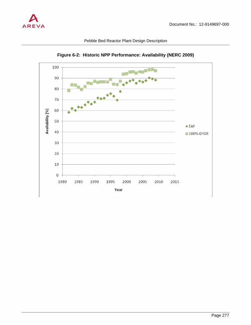
Document No.: 12-9149697-000
Pebble Bed Reactor Plant Design Description
Page 277
PROPRIETARY
Figure 6-2: Historic NPP Performance: Availability (NERC 2009)

Document No.: 12-9149697-000
Pebble Bed Reactor Plant Design Description
Page 278
PROPRIETARY
Figure 6-3: AVR and THTR Availability

Document No.: 12-9149697-000
Pebble Bed Reactor Plant Design Description
Page 279
PROPRIETARY
6.1.5 Magnetic Circulator Bearings
Magnetic bearings are presented as an alternative design in Section 3.3.6. This potential advancement recommends the consideration of the alternative bearing design. (Ref. [17], [18], [19])
6.1.5.1 Incentives to Consider Magnetic Bearings for the Main Circulator
Active magnetic bearings are increasingly being used instead of conventional oil lubricated bearings for a large variety of rotating machines in the conventional industry (oil and gas production, power generation, etc).
Among the incentives that motivate industrials to adopt magnetic bearings, the following can be mentioned:
• Lubricant leakage risk is reduced to zero
• Wear reduced to zero in normal operation
• Improved vibration management possibilities (higher rotating speeds hence are achievable)
• Improved diagnostic intrinsically provided by the regulation system (e.g. detection of loss of a blade by vibration measurement)
• Lower maintenance needs
In the particular case of a 200 MWt PBR, the main incentive would be the oil leakage risk suppression for two reasons:
• The oil ingress inside the primary circuit shall be avoided because the management of primary helium corrosion potential on structures relies on a tight control of its impurities concentrations. Complementary, it shall be mentioned that moisture monitor cells performance may be affected by oil deposit on its surface, as shown by Peach Bottom experience (see hereafter)
• The experience feedback with conventional bearings in past HTGR is mixed. The German AVR and THTR have operated very well with oil lubricated bearings (no leak reported) whereas the American HTGR experienced several difficulties (Ref. [20]):
o Peach Bottom: It was shown that oil ingress originated in the compressor (oil lubricated bearings). Approximately 100 kg of oil entered the reactor.
o Fort Saint Vrain had a helium circulator with water-lubricated bearings. Leakages of these bearings caused several water ingresses. It was a common problem at FSV, responsible for a large portion of the reactor unavailability.
6.1.5.2 Description of Active Magnetic Bearings associated with Catcher Bearings
6.1.5.2.1 Magnetic Bearings
Magnetic bearings shall control and maintain the rotor stability and support radial and axial loads in all operating modes. They must be emergency-supplied by specific means (batteries…).

Document No.: 12-9149697-000
Pebble Bed Reactor Plant Design Description
Page 280
PROPRIETARY
There are two radial bearings (upper and lower instead of the journal oil bearings) and one axial bearing (instead the oil thrust bearing), each associated with a catcher bearing as a backup. Each magnetic bearing is arranged with a catcher bearing in a single unit.
Magnetic bearings are associated with a control system. Sensors detect the shaft position and generate a signal, for the magnetic bearings control system, in order to correct the shaft position if required.
The radial magnetic bearing is a cylindrical magnetic guide composed of electromagnetic steel sheets fixed on a bush which is fitted on the shaft. Each radial bearing has a set of radial displacement sensors. The sensing elements are inductance coil mounted on ferromagnetic core. They are rigidly fixed to an intermediate bush which is itself fixed to the magnetic bearing’s stator.
An example is given in Figure 6-4 for illustration.
As for the radial bearing, the axial magnetic bearing consists of a stator part, a rotor part, displacement sensors (to measure rotor axial displacement in this case) and an electronic control system.
6.1.5.2.2 Catcher Bearings
The catcher bearings are conventional bearings provided to prevent contact between the rotor and the static circulator parts upon magnetic bearings unintended loss of power or malfunctions (see Figure 6-5). They can also support loads from the rotor during maintenance operation, stand-by conditions and during normal startup and trips.
Catcher bearings are complex systems consisting of friction cones and ball bearings.
The catcher bearings are not directly connected to the rotor (small gap) and do not rotate during normal operation of the magnetic bearings. The contact to the rotor is provided by the friction cones in case of failure of the magnetic bearings system.
The friction cones avoid unacceptable high acceleration of the ball bearings (they provide a “soft” acceleration) and serve as an emergency redundancy in case of blockage of the ball bearings. The cones also contribute to adjust the eccentricity and to reduce vibrations and precession movements of the vertical rotor. The latter function is supported by a spring mechanism.
The balls can be made of silicone nitride (more robust than steel) or a particular grade of steel. They should be covered with a lubricating material such as MoS2.
Dry lubrication has to be developed for bearings and cones.
Figure 6-6 details the principle of the Axial – Radial Catcher Bearing and the Radial Catcher bearing.

Document No.: 12-9149697-000
Pebble Bed Reactor Plant Design Description
Page 281
PROPRIETARY
6.1.5.3 First Overview of Technology Readiness
6.1.5.3.1 State-Of-The-Art Power Levels and Feasibility of Active Magnetic Bearings
A rapid survey shows that state-of-the-art magnetic bearings are used in conventional turbo-machinery at power levels comparable to, and even higher than, the 2.95 MWe main circulator of the HTR-Module. One can cite, for examples:
• Eight 3.3 MW turbo-expanders in North Sea Natural Gas Sleipner East and West are operated by the Norwegian Statoil. The turbo-expanders are manufactured by the French Cryostar and the magnetic bearings provided by the French S2M. (Ref. [21])
• The German Thyssengas operates a 2300 km natural gas distribution pipeline between the North Sea and the Ruhr area. The Hünxe compression station uses three Man Turbo booster compressors of powers of around 6 MW. The compressors are manufactured by the German Man and the magnetic bearings provided by the French S2M. (Ref. [22])
• The new Rutledge natural gas compressor station, owned by Columbia Gas Transmission Corp. at Fallston in Harford County, MD. (USA) uses three compressors driven by 3 MW electrical motors (Alstom). The compressor units were built by Sulzer Turbo and the magnetic bearings were provided by S2M. (Ref. [23])
• The American Dresser-Rand’s DATUM® C centrifugal compressor is an integrated, electric motor-driven compressor designed for natural gas pipeline and process gas applications that uses magnetic bearings for its compressor as well as for its motor. Powers of 10 MW are achievable. (Ref. [24])
• Man Diesel & Turbo proposes the HOFIM™ Sealed compressor line, equipped with magnetic bearings (S2M). The proposed powers range from 3 to 25 MW. (Ref. [25])
• GE is developing the Blue-C compressor line for subsea gas boosters or re-injection compressors. This product line development intends to propose industrial solutions for subsea compressors of up to 15 MW using magnetic bearings by 2014. (Ref. [26])
• Waukesha Bearings Corp. is a world-wide supplier of engineered magnetic bearing solutions for turbo-machinery applications in the oil and gas, power generation, and marine industries. Their reference list includes over 40 installations in turbo-machinery larger than 20 MW. (Ref. [27])
These examples account neither for the feasibility nor for the interest of magnetic bearings for a 200 MWt PBR (many HTGR specificities may be ignored), but show that the power of the main circulator of a 200 MWt PBR should not be a priori considered unfeasible with regard to state-of-the-art magnetic circulator technology.
Nonetheless, previous experience on HTGR circulators shows there are no major feasibility issues for magnetic bearings on HTGR main circulators of a power of less than 4 MWe. Magnetic bearings have been applied in applications up to a rotating mass of approximately 80 tonnes.
A particular care should however be accorded to the associated catcher bearings. Operation in dry helium particularly is a major specificity for these systems.

Document No.: 12-9149697-000
Pebble Bed Reactor Plant Design Description
Page 282
PROPRIETARY
6.1.5.3.2 Previous Test Results on Catcher Bearings for the HTR-500 Project
The catcher bearings described in Section 6.1.5.2.2 have been tested on the FLP 500 experimental facility in the framework of the HTR-500 German Project, following the THTR Project. The facility is located at the Technical High school in Zittau, Germany, which is the largest experimental facility for magnetic bearings with a vertical rotor operating in helium, representative pressure and temperature.
The reference design for the test of the catcher bearings was the HTR-500 auxiliary circulator with an impeller radius of 1250 mm. On the experimental facility, the vertical rotor is suspended by magnetic bearings and is provided with an electrical braking device. The maximum speed is 7200 rpm and its weight is 1320 kg.
Considering the HTR-Module circulator dimensions (impeller radius of 950 mm), rotational speed (4400 rpm) and rotating mass (1400 kg), the experimental tests should, to a certain extent, be representative of the HTR-Module needs. A specific study would however be needed to precise this point by exhaustively identifying the parameters of importance (in particular, moments of inertia should be compared, rather than rotating mass).
The feasibility of this type of catcher bearings with friction cones and ceramic balls is not an issue, a feasibility threshold being estimated for a rotating mass of approximately 80 tonnes (that of the HTR-Module main circulator is 1.4 tonnes).
However, catcher bearings can only withstand a limited number of actuations (magnetic bearings unintended loss of power or malfunctions), notably because the wear of the friction cones. Up to now, tests carried out on the FLP 500 facility have shown maximum numbers of actuations between 3 and 13, depending on the material considered and the lubrication.
In the 200 MWt PBR, an appropriate design number of actuations of the catcher bearings would have to be defined.
Most of the time, the power supply of the magnetic bearings would not be switched off when the main circulator is tripped, so that the catcher bearings would not be used for every circulator trip.
On the other hand, each unexpected loss of power to the magnetic bearings would request the catcher bearings back-up. So, the catcher bearings number of actuations will be closely linked to the reliability of this power supply, which would be another parameter that may be optimized (e.g. with redundancy) in case the catcher bearings technology does not sustain a sufficient number of actuations.
Tests will need to be run in helium to study the achievable number of actuations, and hence the lifetime of the catcher bearings with consideration to the power supply reliability.
6.1.5.3.3 Integrated System
Individual systems development is not sufficient to proceed to final design of the circulator with magnetic bearings. The development and qualification of the regulation system associated with the integrated magnetic bearings / catcher bearings / shaft would be a major step to be completed before the final design of the circulator.
In addition, the impact of magnetic bearings and catcher bearings on the overall dimensions of the circulator, on electrical systems complexity inside the cavity and their cooling system, as well as on the steam generator pressure vessel design should be determined before selecting the magnetic bearings option.

Document No.: 12-9149697-000
Pebble Bed Reactor Plant Design Description
Page 283
PROPRIETARY
6.1.5.4 Design Data Needs (DDN): Primary Gas Circulator Rotating Assembly with the Magnetic Bearings and Catcher Bearings
Tests objective
The aim of the tests is to achieve the demonstration of the magnetic bearings with the rotating equipment assembly (motor, bearings, and rotor) and its regulation system throughout the whole range of operating conditions. The tests will enable to detect potential vibrations issues and revise either the regulation software or the bearing and rotor design if required.
The tests should also demonstrate the ability of the catcher bearings to be activated the appropriate number of times (to be defined with consideration, notably, to the power supply reliability) without any loss of functionality.
Test conditions
A test in helium is highly recommended since the tribology of the catcher bearings under helium is much different to that in air. The tests should cover the full operation range in high temperature and pressurized helium environment.
An integrated rotating equipment assembly is required for this test. It could be performed in a facility such as the FLP 500 experimental facility in Zittau, Germany, as long as the facility could operate in a helium atmosphere (presently only operating in air, but feasibility studies of helium operation have been performed).
If these tests are not carried out in helium but in air, the commissioning phase will have to integrate specific tests in helium before starting the plant.
6.1.5.5 Conclusion on Magnetic Bearings
Magnetic bearings are widely used in large industrial turbo-machinery of large power because they have the potential of several operational advantages, including reliability. The American HTGR experience feedback suggests that suppression of the lubricant ingress risk would be an attractive feature of future HTGR main circulators.
Therefore, the magnetic bearings may be an attractive option for a future 200 MWt PBR and should be evaluated in details against lubricated bearings to support an appropriate choice.
Special consideration should however be granted to the associated catcher bearings and their ability to withstand a sufficient number of actuations in dry helium.
Integrated tests accounting for the behavior of both magnetic bearings, catcher bearings and their regulation system in representative environment will be needed for qualification. The impact of this change on the overall design of the circulator, its cooling and electrical systems as well as the impact on the steam generator pressure vessel design should be evaluated before going from conventional lubricated bearings to advanced magnetic bearings.

Document No.: 12-9149697-000
Pebble Bed Reactor Plant Design Description
Page 284
PROPRIETARY
Figure 6-4: Radial Stator of a magnetic bearing and sensors, diameter 360 mm (FLP 500)

Document No.: 12-9149697-000
Pebble Bed Reactor Plant Design Description
Page 285
PROPRIETARY
Figure 6-5: Example of Rotor Supported by Magnetic Bearings and Catcher Bearings
Axial – Radial Catcher Bearing
Axial Magnetic Bearing
Top Radial Sensor
Top Radial Magnetic Bearing
Asynchronous motor
Bottom Radial Sensor
Radial Catcher Bearing

Document No.: 12-9149697-000
Pebble Bed Reactor Plant Design Description
Page 286
PROPRIETARY
Figure 6-6: Principle of Axial-Radial and Radial Catcher Bearings
Axial – Radial Catcher Bearing
Radial Catcher Bearing
Shaft
Shaft
Wear / Friction point
Ball bearings
Ball bearings
Compression spring
Friction cone
Friction cone
Friction cone

Document No.: 12-9149697-000
Pebble Bed Reactor Plant Design Description
Page 287
PROPRIETARY
6.2 Long-term Advancements
The following long-term advancements may be considered in future generations of PBR plants. These advancements are identified to highlight the capability of the technology.
6.2.1 Long-Term Potential for Pebble Bed Reactor Technology
The current HTR-Module PBR concept was developed to serve a wide variety of potential applications including efficient electricity production, supply of high temperature process steam, and various cogeneration configurations. In addition, since the HTR-Module was first developed, various potential advancements have been identified that would improve the performance and reliability of the concept without changing its basic characteristics. Some of these advancements are discussed in adjacent subsections.
The focus of this section is to understand the long-term potential of the technology, going beyond the basic HTR-Module configuration. The potential of HTGR technology to go beyond traditional configurations and applications has long been recognized. HTGRs, including PBRs, have the potential to go to even higher temperatures to serve very high temperature applications, they have the potential to support diverse power generation and energy transfer configurations, and they have exceptional fuel cycle flexibility.
6.2.1.1 Very High Temperature Capability
The current HTR-Module concept can already support numerous applications with high temperature process steam in the range of 500-550°C. With additional incremental development, the potential exists to supply heat at even higher temperatures, enabling the direct supply of process heat to higher temperature chemical processes and increasing the efficiency and yields of current chemical processes.
With current materials, core outlet temperatures in the range of 700-750°C are readily achievable. Core structural materials are capable of temperatures well beyond this range. Fuel operating temperatures are placed under increased strain as reactor outlet temperature is increased, but core designs with outlet temperatures in the range of 900-950°C are achievable. Limited operating experience already exists at these temperatures from the AVR and HTR-10 PBRs. Of course, safety analyses would take into account the higher fuel operating temperatures for such applications.
The greatest challenge to very high temperature applications is the heat delivery system. Direct heat delivery systems require some form of intermediate heat exchanger (IHX) to transfer the heat from the primary loop to a secondary heat transport loop. Various IHX and heat transport configurations have been studied (Ref. [28], [29], [30]) during the NGNP program. Significant materials challenges remain to be resolved for very high temperature IHXs. Metallic alloys exist which have the potential to operate at reactor outlet temperatures as high as 950°C with resulting heat delivery temperatures in the range of 900°C. However, these alloys are very close to their limit at those temperatures, and component lifetimes would be limited. Completely ceramic concepts offer the potential of significant performance advances, but substantial development work remains to be done. Traditional tubular IHX concepts have been demonstrated at 950°C, but these are expected to result in high plant cost. (For HTR-Module, there was a conceptual design for a tubular IHX operating at 950°C.) On the other hand, compact plate IHX concepts would be more attractive in terms of cost, but are much more demanding in terms of material performance and design. Nonetheless, while additional IHX development will be needed, workable solutions are thought to be achievable with adequate research and design innovation.

Document No.: 12-9149697-000
Pebble Bed Reactor Plant Design Description
Page 288
PROPRIETARY
For any process heat application, the potential transport of tritium to downstream chemical processes must be considered. Tritium is produced as a natural consequence of reactor operation. Like other forms of hydrogen, tritium has high permeability in most materials and is readily transferred to the secondary heat transport loop. In water/steam secondary loops, tritium is more readily captured in the water molecules. However, in a gas secondary heat transport loop such as might be used for very high temperature applications, the tritium would remain mobile and could ultimately be transferred to process products.
Various measures are available to remove tritium from the primary and secondary loops. Measures are also available to limit the transfer of tritium between the primary and secondary loops and between the secondary and process loops. In addition, the acceptable concentration for tritium in process products varies significantly depending on the nature of the chemical product and its use as well as what locality governs the facility. Ultimately, detailed analysis and design will be required to ensure acceptable management of tritium contamination in the process heat facility.
The PBR concept clearly has the potential to serve higher temperature direct process heat markets in the future. The challenges imposed by the required temperatures for the reactor itself are fairly manageable. The greater challenge lies with the energy transport system and the IHX.
Moreover, the PBR concept is particularly well suited for very high temperature applications requiring a large temperature difference between core inlet and outlet temperatures. The thermal hydraulics of the PBR core makes it very attractive to use moderate reactor inlet temperatures even for very high outlet temperatures. This makes it practical to use more conventional materials for most of the primary circuit, since the reactor cold leg temperature (which accounts for most of the loop) can still be relatively low.
6.2.1.2 Direct Power Generation
The PBR concept is also adaptable to future power generating systems. While the reference HTR-Module provides good power generation efficiency through the Rankine cycle using high temperature steam, improved performance may be achievable using advanced systems such as the direct Brayton cycle (Ref. [28]).
The direct Brayton cycle uses the primary helium coolant directly as the working fluid in the gas turbine engine. This has the advantage of eliminating significant secondary equipment, and it avoids the thermodynamic inefficiency of heat transfer to a secondary working fluid. Moreover, at high reactor outlet temperatures (e.g., 850°C or above), the inherent net generating efficiency of the direct Brayton cycle is naturally higher than for a comparable Rankine cycle.
The high outlet temperature potential of the PBR is a good fit with the direct Brayton cycle. The turbine inlet temperature is essentially equal to the reactor outlet temperature. As this temperature is increased above 850°C, the Brayton cycle efficiency increases dramatically. Since PBR operating experience has demonstrated reactor outlet temperatures of 950°C, very high turbine inlet temperatures should be achievable with resulting performance advantages.
However, the high pressure drop of the PBR core negates some of this advantage. Bayton cycle efficiency is very sensitive to pressure losses due to flow resistance in the system, especially in the high temperature part of the loop. Thus the flow resistance of the pebble bed core has a negative impact on plant performance.
In order to obtain reasonable pressure ratios, most direct HTGR Brayton cycle concepts are recuperated. This is significant for PBR systems in particular, since it means that the core inlet temperature is relatively higher than it

Document No.: 12-9149697-000
Pebble Bed Reactor Plant Design Description
Page 289
PROPRIETARY
would be for a typical PBR. This might necessitate extra thermal protection or cooling of the helium pressure boundary. This also requires a relatively higher coolant flow rate which further increases core pressure drop.
The most challenging aspect of deploying a PBR direct Brayton cycle system is the development and integration of the power conversion system hardware. The helium turbine and compressor and the high effectiveness recuperator will all require state of the art technology.
Clearly a PBR direct cycle power generating system is feasible. Ultimately, the selection of a more advanced power generating system for the PBR would be a complex decision involving development cost, capital cost, and system performance. Other options such as the supercritical steam cycle would also pose attractive options.
6.2.1.3 Alternate Fuel Cycles
The neutronic characteristics of HTGRs allow substantial fuel cycle flexibility. The graphite moderated core of the modular HTGR provides a neutron spectrum that is more adaptable than typical LWRs (Ref. [31], [32]). This advantage applies to all HTGRs, including PBRs.
Fuel cycle studies have evaluated a variety of scenarios to take advantage of this flexibility. Cycles using MOX and even pure plutonium fuel have been evaluated in detail. Special cycles designed to burn minor actinides and cycles using LWR spent fuel as input have been widely discussed. There is also some renewed interest in HTGR thorium cycles, building on early HTGR development which was based heavily on thorium cycles.
Many of the more advanced fuel cycle concepts that have been proposed include the use of multiple fuel forms. For example, some actinide burning schemes use both driver fuel and burner fuel. Other schemes use different fissile and fertile fuel components. A critical consideration for the PBR is how these different components are arranged in the core. The homogenous well-mixed PBR core does not allow effective spatial zoning. In PBR designs, different regions can be supplied with a different type of pebble, but detailed control is not possible. Moreover, axial zoning is not possible. Clearly precise zoning of different types of fuel forms within the core is not practical for the PBR.
However, the PBR does offer an alternate type of fuel loading flexibility that is very unique. Due to the fact that the average pebble makes several passes through the core over its lifetime, the possibility exists to have different residence times in the core for different constituents. Some fuel elements could be passed through the core many times, while other elements with a different fuel type might only make a few or even just one pass. This would allow different fuel forms to be targeted for different fluences and burnups within the same operating reactor.
The online refueling capability of the PBR is also beneficial for alternate fuel cycles which may require relatively short irradiation times. This permits such cycles to be implemented without the need for frequent refueling shutdowns.
6.2.1.4 Additional Development Needs for Long-Term Concepts
In general, additional incremental development would be required to deploy the advanced systems discussed in this section. This research and development is beyond the limited development that would be needed to deploy the reference steam cycle concept for the near-term high temperature steam market.
For very high temperature applications, substantial additional work will be required for the IHX. Large tubular IHX concepts have been successfully demonstrated for very high temperature conditions. However, such configurations are relatively expensive, and additional work would be necessary to deploy such a component in

Document No.: 12-9149697-000
Pebble Bed Reactor Plant Design Description
Page 290
PROPRIETARY
today’s environment. Compact IHXs may offer advantages for cost reductions of the heat exchanger, but substantial additional development would be required for these more advanced concepts. Ultimately, the ideal IHX would be a ceramic heat exchanger. Ceramic IHXs will require far more development work than metallic heat exchangers, but if the technology can be brought to maturity, it will offer substantial performance advantages.
For the direct Brayton cycle, further work developing and qualifying helium turbomachinery is needed. Perhaps the greater challenge for such systems is in the optimization and verification of integrated Brayton cycle power generating systems. The integration of the overall system will have a very large impact on the system’s performance and reliability.
For all of the advanced systems, further development of high temperature materials will be required. In particular, the development and qualification of high temperature ceramic composites for primary circuit structures would be very beneficial. While very high temperature PBR systems can theoretically be developed using current materials, new materials and extended capabilities for existing materials will make these systems much more practical by providing greater design flexibility and increased margins.
For all applications additional fuel development work would be either beneficial or mandatory. For the advanced fuel cycle concepts, qualification of alternate fuel particle designs for plutonium and/or actinides would be necessary. For very high temperature concepts, the development and qualification of advanced fuel particle designs such as ZrC-based systems may offer significantly improved margins for high temperature operation.
6.2.1.5 Conclusion
The reference steam cycle PBR concept offers a sound starting point for further development. The PBR concept inherently offers a broad range of capabilities that can support additional new markets and energy needs.
With suitable additional development work tailored to the specific application of interest, the experience gained demonstrating the current PBR concept will provide a solid foundation for advanced concepts in the future.
6.2.2 Supercritical Steam Cycle
The pebble bed reactor (PBR) is a helium cooled design with the primary coolant loop operating at a temperature of approximately 1292°F (700°C). Unlike other nuclear reactor designs with lower reactor operating temperatures, the ability to generate higher temperature and pressure superheated steam allows more efficient power conversion. Raising steam generator temperature and pressure increases power conversion efficiency, but is limited by available materials and the economics associated with construction of increasingly high pressure vessels and steam turbines. Higher efficiency power cycles, such as current supercritical and proposed ultrasupercritical designs, increase the amount of useful energy which can be produced.
This is important for capital intensive nuclear reactor designs because increasing the conversion efficiency has the same economic effect as reducing the capital cost. High power conversion efficiencies dramatically improve economics, since the $/kW value (considering power as the primary product) is inversely proportional to conversion efficiency. A nuclear island supporting a higher power conversion efficiency will have correspondingly higher value relative to conventional power and cogeneration units. When comparing pebble bed reactor technology to proposed small light water reactor (LWR) designs, the benefits are substantial. A small LWR would have to produce almost twice the energy and utilize almost twice the nuclear fuel to produce the same electricity that would be needed for a PBR reactor with a high efficiency power cycle.

Document No.: 12-9149697-000
Pebble Bed Reactor Plant Design Description
Page 291
PROPRIETARY
There is considerable experience with supercritical coal fired power generation units. However, given the differences in boiler and auxiliary power requirements unique to coal power plants, it is more useful to consider turbine heat rate rather than overall net plant heat rate to understand how steam cycle improvements could impact nuclear power cycles. State of the art subcritical coal fired units have turbine heat rates on the order of 7600 BTU/kWh (efficiencies on the order of 45%). Turbine heat rate neglects boiler losses and plant auxiliary loads such as emissions control equipment and coal handling). Current state of the art supercritical coal fired boiler designs have turbine heat rates approaching 7000 BTU/kWh (efficiencies exceeding 48%) and further advancements in higher temperature steam cycles could raise these efficiencies considerably higher, exceeding 60%.
Supercritical cycles require higher cost equipment primarily due to higher pressure piping and heat transfer surfaces, as well as higher discharge pressure feed pumps and, due to the higher inlet pressure and temperature, more expensive turbine generators. When applying supercritical cycles to a PBR plant, these higher energy conversion capital costs leverage the effectiveness of the much higher cost nuclear island and can dramatically reduce the cost per kW produced. The efficiency advantage of supercritical steam cycles over subcritical steam cycles increases with steam turbine size because efficiency losses due to leakage around turbine blades are greater with very small turbine blade lengths. At larger capacities, the additional efficiency and output make supercritical steam cycles more economical than subcritical steam cycles at moderate or higher electricity prices. It is likely that small nuclear plants will be more economical at higher electricity prices, encouraging the application of higher efficiency conversion cycles.
The trend that large new fossil units are utilizing supercritical steam cycles should continue in the future, driven by the need to improve efficiency in response to higher values of electricity and the economics of reducing emissions. The current state of the art for ultra supercritical (USC) plants in Europe and Japan are steam conditions of 4350 psig (300 bar) and 1112°F/1148°F (600°C/620°C) corresponding to a net plant thermal efficiency of 38.5% on a higher heating value (HHV) basis. Steam conditions for U.S. supercritical plants are expected to gradually increase to match the overseas experience by ~2015. Steam temperatures in the 1400-1600°F (760-871°C) range, which would allow net plant thermal efficiency to approach 50%, are not likely to be achieved for several decades, but could conceivably become available in the 2030+ time frame.
The major high temperature components in a Rankine cycle plant that provide the greatest challenge to further development are (1) tubing material for the final superheater and reheater, (2) material for superheater outlet headers, reheater outlet headers, main steam piping, and hot reheat steam piping (all thick-wall components), and (3) material for the high temperature steam turbine components. The major roadblock to further advances in steam conditions and efficiency for USC plants are materials for high temperature components. The issues of greatest concern are (1) creep resistance, (2) resistance to high temperature external corrosion, (3) resistance to internal oxidation at high temperature, and (4) thermal fatigue and creep-fatigue damage in thick-walled components. The problems with external corrosion at high temperature are peculiar to coal fired boilers and would not be an issue in the helium environment of a PBR steam generator. However, the other issues are directly applicable to the PBR application. Creep resistance is always a focus of high temperature materials research but less is known about resistance to internal steam oxidation. Steam oxidation, which will be equally an issue in the PBR application, may be more of a limiting factor than creep resistance at temperatures exceeding 1100°F (593°C).
Because of their low cost and other advantages, ferritic alloys will continue to be used extensively (used in more than 50% of pressure parts) in USC boilers. However, their relatively low chromium content makes them vulnerable to high temperature coal ash corrosion and steam side oxidation. This weakness will limit their use at very high metal temperatures. As discussed earlier, coal ash corrosion will not be a problem for the PBR application but internal oxidation will. For very high metal temperatures, advanced nickel based “super alloys”

Document No.: 12-9149697-000
Pebble Bed Reactor Plant Design Description
Page 292
PROPRIETARY
are being developed which could satisfy USC operating conditions in steam generator components. Leading candidates for consideration are Inco 740, Haynes 250, HR6W, and Inco 617. These materials have the required creep strength and their high chrome content provides resistance to steam side oxidation. These materials have the potential to allow metal temperatures up to 1450°F (788°C).
A preliminary comparison of a subcritical and supercritical steam cycle was completed for an anticipated PBR commercial plant power-only configuration. Results indicate that the net plant thermal efficiency can be increased from about 40% to about 44% by increasing main steam conditions from 2755.6 psia/986°F (190 bar/530°C) for a non-reheat subcritical power cycle to 3704 psia/1125°F/1125°F (255.4 bar/607.2°C/607.2°C) supercritical single reheat configuration. This 10% improvement in efficiency corresponds to a reduction in cost/kW, although higher costs for high energy equipment and piping have to be considered. For this comparison, power for feedwater pumps, condensate pumps, circulating cooling water pumps, cooling tower fans, and an allowance for balance of plant loads plus the helium circulators was deducted from power production to provide a more meaningful comparison of efficiencies
The conclusion of this limited review is that significant improvements to the PBR power generation efficiency are available by employing supercritical and possibly ultrasupercritical steam cycles if they become available before commercialization of the PBR technology. The ability to achieve higher conversion efficiencies distinguishes HTGRs from other reactor designs with lower operating temperatures. Research to develop key components which enable higher conversion efficiencies should be considered to leverage the value of HTGR technology. Economic analysis of higher efficiency steam power cycles should be considered to further evaluate the merit of such research for HTGR applications.

Document No.: 12-9149697-000
Pebble Bed Reactor Plant Design Description
Page 293
PROPRIETARY
7.0 SITE CONSIDERATIONS
This section addresses the selection and development of a suitable site for deployment of a pebble bed reactor. Key parameters that affect the planning and cost estimating process are identified and a representative site is defined to support portions of the technology assessment, particularly the cost and schedule report.
7.1 Land and Improvements
Site Location
The representative site is located in the southeast United States, in the Gulf Coast states. The land slopes gently to a distant river and is inland. The area has extensive wetlands surrounding the plant. The proposed site is generally level.
The geographical location of the proposed project will be defined based on a site selection report. The site selection will be based on maintaining the required distance from property boundaries and achieving the maximum distance from existing industrial manned facilities. The project site is located close enough to industrial facilities that it requires no self-contained utilities.
Geotechnical Features
For this project, descriptions of typical site characteristics were used.
The depth to the groundwater table is approximately 5 feet below grade.
The top 15 feet of soil is clay and silty clay with silt and sand lenses. The consistency of the soil is soft to medium. Because of the loads of the structures, a deep soil boring program will be required. Supplemental geotechnical investigations, including drilling borings, obtaining samples of subsurface materials, performing laboratory tests, field tests, and geophysical investigations, are required during the conceptual design phase of the project to develop site-specific subsurface information for design of the facilities in accordance with recommendations in US NRC regulatory guides.
Site wide engineered fill and build up the site is not required. It is noted that differential settlement is an issue for all small structures on the site and over excavation and select backfilling are common practices.
The reactor building is partially embedded into the project site to provide a stable foundation and to reduce seismic amplified response. A future study is recommended to optimize the depth of bury taking into consideration seismic design and requirements to protect the reactor from natural and manmade phenomena.
Additional assumptions:
• There are no underground obstructions on this site.
• There is no expected environmental contamination on this greenfield site.
• Hydrology, climatology, and seismic requirements require further study in the site selection process.
• The orientation to prevailing winds is considered in the context of surrounding chemical facilities.

Document No.: 12-9149697-000
Pebble Bed Reactor Plant Design Description
Page 294
PROPRIETARY
Roads, Parking, and Paving
The representative site has high groundwater and poor soil conditions. The pavement design would be required to support traffic loads and reduce the effects of uneven settlement of the base material.
The roadway system supports all the vehicular transportation throughout the site. The roadway system will be developed and will incorporate the requirements of material transport vehicles, normal roadway loadings, on site handling (cranes, fork trucks etc.), passenger vehicles, and pedestrians. The system will also incorporate parking needs and vehicle storage needs. Concrete pads will be located at all receiving, queuing, and holding areas. Concrete pad and spill containment structures are provided for diesel fuel storage tank /vault and diesel fuel fill stations. The roadway system must be coordinated with the building general arrangement and the earthwork and landscaping requirements of the site.
The roadway system is to be physically, dimensionally, and functionally compatible with trucks transporting fuel materials, as well as all service and support vehicles. All roadways are designed and constructed of sufficient size and strength to routinely carry truck traffic according to AASHTO guidelines. The size and configuration of the roads and queuing area in the protected area and access into the generating area are able to readily accommodate transport of the fuel and waste material shipments. The areas around the reactor and support buildings are paved to facilitate maintenance and to locate additional equipment as it is identified.
Paved parking areas are provided at all buildings to accommodate the anticipated organizational vehicles, supply vehicles, maintenance vehicles, etc. The design of pedestrian walkways complies with OSHA requirements. Parking is provided outside the perimeter fences for operations and construction forces.
Earthwork activities are based on the criterion that the site will be graded to achieve a relatively consistent elevation, while providing storm water drainage during construction and operations. Grades ensure that storm water flows away from the facilities and overland to the drainage system. Erosion control measures are included as necessary and are required to minimize the impacts to areas adjacent to the site. Landscaping consists of shrubs, trees perennials and groundcover commensurate with the site location and architectural treatments.
Access Control
The plant shall be fenced. The number of entrances for emergency assess will have to be studied further when an actual site is decided. As a minimum, all entrances will have secure access control. The gatehouse will be located adjacent to the roadway entrance.
The Nuclear Controlled Area shall be inside a separate security fence. This area is also called the nuclear island and shall include storage areas for nuclear fuel and nuclear waste. The entrance road into the area shall be controlled by the security building.
Utilities
Normal industrial site utilities include potable water, fire protection, plant water, sanitary sewer, and wastewater are to be supplied by the existing plant. Other site utilities, including communications and electricity, are to be supplied by municipal system sources. The details regarding utility needs, availability, connection locations will be site specific and developed at a future design study. In addition, construction methods and piping details will be required. The site chosen for this example has high groundwater and would require buoyancy calculations for all underground structures and piping. The structures and pipes would require sand backfill and could require mats over large trenches to reduce the effect of uneven settlement.

Document No.: 12-9149697-000
Pebble Bed Reactor Plant Design Description
Page 295
PROPRIETARY
The project will be located adjacent to an existing plant with capacity to supply water to the project. The potable water system for domestic use will be required for distribution to every manned building in the project. The demand will be limited due to the relatively small population. The fire protection system is required for distribution to every manned building in the project. The potable water system trunk line into the project could serve both domestic use and fire protection. However, supply to each building will have to be separate feeds from the trunk line. The plant water system is a larger capacity, has few connection points, is not a potable water system, and shall be kept separate from the potable water system. It is suggested that both system trunk lines be installed under the roadway system. Because of the poor soil conditions bedding and backfilling the pipe trenches with select material will be required.
The project will be located adjacent to an existing plant with capacity to receive wastewater from the project. The sanitary sewer from domestic usage will be discharged from every manned building. The flow will be minimal and shall be gravity flow within the project area. A lift station can be added at the connection point to the existing system if grades are unfavorable. The wastewater collection will be mainly from the cooling tower blow down. After the collection, the wastewater will be pumped to the existing system. The domestic sanitary sewer and wastewater systems shall be separate systems. There shall be no contaminated water from the reactor building introduced to these systems.
Solid waste handling should be to normal roll off dumpsters. No solid waste receptacles should be stationed within the nuclear island area. Radioactive waste handling is addressed in the PBR design description.
Storm water System
The storm water drainage system is in accordance with state and local standards. This site shall be designed for a 10-year, 1 hour rainfall event as a minimum design criteria. The drainage system layout is designed to best meet the operational requirements of the facility. The system is constructed as economically as practical, taking into consideration topography, ultimate development of the drainage area possible future expansion outfall locations, and coordination with any existing drainage systems and other existing or future underground utilities.
Environmental Monitoring System
Erosion control facilities will be designed in accordance with state regulations. The best management practices for stormwater treatment could include several categories. Channel systems could be water quality swales or biofilter swales. The detention/retention basin systems combine many sizes and shapes of basins that can be blended into the site landscaping. The filter system could be organic filters or sand filters. Mechanical water quality inlets such as oil grit separators can be used if strict requirements need to be satisfied.
Construction Transportation (Major equipment)
Transportation of major equipment such as the reactor vessel and steam generator to the site by a combination of barging to the closest location and then transporting over rail or road should be studied as the first option. Often this approach is very costly due to the extent that modifications to bridges and other road structures are required to accommodate the size and weight of these two components. Discussion on an alternative approach of transporting the major components in transportable pieces and then performing assembly at or the near the site should be studied. Once an actual site is chosen then detailed studies of the transportation routes and potential modularization for major components are recommended for early in the conceptual design phase.

Document No.: 12-9149697-000
Pebble Bed Reactor Plant Design Description
Page 296
PROPRIETARY
7.2 Geotechnical Considerations
The representative site is located in the southeast United States, in the Gulf Coast states. One important geotechnical consideration for site selection is the shear wave velocity Vs at the founding level of the safety-related structures. If Vs is too low, the soil is likely to be too compressible and structure settlements are likely to be unacceptably high. Therefore, a lower bound shear wave velocity needs to be considered for the site selection process. This section discusses the shear wave velocity ranges identified for the HTR-Module design and briefly summarizes subsurface conditions at four nuclear power plant sites in the Gulf Coast area, with emphasis on the shear wave velocity at the founding level of safety-related structures. A minimum shear wave velocity value is proposed. The potential need for a common mat for the reactor building and reactor auxiliary building also is discussed.
HTR-Module reactor building founding depth and shear wave velocities
The HTR-Module safety analysis report (Ref. [5]) indicates the reactor building will be founded on a rigid mat, with the top of mat located 41.7 ft (12.7 m) below grade, and the bottom of mat approximately 50.8 ft (15.5 m) below grade.
The safety analysis report also identifies two shear wave velocity (Vs) profiles for the purpose of establishing response spectra for the safe shutdown earthquake and operating basis earthquake:
A. Vs < 1300 ft/sec (<400 m/sec)
B. 1,300 ft/sec < Vs < 3,600 ft/sec (400 m/sec < Vs < 1,100 m/sec)
Regarding Range A, materials with Vs of 1,300 ft/sec typically include heavily overconsolidated sand or clay, or glacial till. Values of Vs for soft clays can be as low as approximately 200 ft/sec.
Regarding Range B, materials with Vs up to 3,600 ft/sec typically include sedimentary rocks such as shale, and highly fractured or decomposed metamorphic or igneous rocks. Such materials are unlikely to be encountered at or near the founding level of safety related structures in the Gulf Coast region.
Grand Gulf ESP Site
The Grand Gulf site is being considered for one or more reactor units to be constructed west of existing Unit 1 (operational) and Unit 2 (not completed). Subsurface information was obtained from the U.S. NRC safety evaluation report (SER) (Ref. [33]) on the application for an early site permit.
The Grand Gulf site is located near Port Gibson, Mississippi, approximately 25 miles south of Vicksburg, Mississippi. The site is located within the Mississippi Alluvial Valley subprovince of the Gulf Coastal Plain. The subprovince includes several interdistributary lowlands, basins, and ridges. Elevations within the subprovince range from 50 ft to 250 ft. The topographic highs along the Mississippi River are remnants of older alluvial deposits that were mostly eroded and removed from the valley. The Mississippi Alluvial Valley is relatively flat with a gentle southward gradient and is characterized by fluvial geomorphic features typical of a braided stream and meandering river system.
The applicant’s plant parameter envelope (PPE) for the Grand Gulf Site referenced the following reactor designs:
• Advanced Canada Deuterium Uranium (CANDU) Reactor (ACR-700) (Atomic Energy of Canada, LTD)

Document No.: 12-9149697-000
Pebble Bed Reactor Plant Design Description
Page 297
PROPRIETARY
• Advanced Boiling-Water Reactor (General Electric)
• AP1000 (Westinghouse Electric Company)
• Economic and Simplified Boiling-Water Reactor (General Electric)
• Gas Turbine Modular Helium Reactor (General Atomics)
• International Reactor Innovative and Secore (IRIS) Project (consortium led by Westinghouse)
• Pebble Bed Modular Reactor (PBMR (Pty) Ltd.)
The proposed Early Site Permit (ESP) site is relatively flat with an elevation of 135 feet. The site is located immediately adjacent to the existing nuclear power plant on the bluff just east of the Mississippi River, with an area about 30 acres. The applicant advanced four cone penetration test (CPT) soundings to a depth of about 100 feet and three borings to a depth of 180–240 feet. The combination of these recent data with previously available boring and sample data provides information on site stratigraphy to a depth of about 240 feet. The applicant stated that information regarding seismic site response characteristics at depths below 240 ft comes from other generic information available for the broad region around the site.
The applicant divided the shallow part of the subsurface materials into five zones, described as follows, from the surface downward:
(1) Localized fill—At various locations across the site, fill was placed to relatively shallow depths to stabilize existing swales while constructing the existing Grand Gulf Nuclear Station (GGNS). These relatively localized fills are no more than 20 feet thick.
(2) Loess—Loess (wind-deposited soil) with a thickness of 55–85 feet forms the surface layer across the site. It is generally composed of relatively uniform inorganic silts of low to moderate plasticity, with some silty clay intervals. The loess shows layering defined by difference in clay contents, color, shell content, and consistency. The engineering properties for different loess layers do not show significant variation. Regionally and locally, the loess shows some minor cementation and soil structures that allow it to stand vertically in cuts and river banks. The CPT soundings show that the loess exhibits layering with a thickness from 6 inches to 40 feet. Standard penetration test (SPT) sample blow counts indicate that the loess is medium-stiff to stiff and has undrained shear strengths from 750 to 1500 psf. Measured shear wave velocities for the loess vary from 590 fps to 1450 fps.
(3) Upland Alluvium—Immediately below the loess is the Upland Alluvium, which consists of an interbedded sand and silty sand material to silty sands with little or no plasticity. Discontinuous layering ranges between 6 inches and 3 feet. The Upland Alluvium is typically well sorted with low fines content and low plasticity. Some of this material may also contain plastic fines interspersed in this zone. The Upland Alluvium is typically a medium-dense to dense formation that the CPT soundings penetrated to some extent. The thickness of the Upland Alluvium varies across the site from as little as 20 feet to as much as 100 feet. Undrained shear strength (ranging from 4000 psf to 8000 psf) of the Upland Alluvium is somewhat higher than that of the loess, and its shear wave velocities vary from 740 fps to as much as 1750 fps.
(4) Old Alluvium—The Old Alluvium consists of interbedded clayey sands, sandy clay, silty sand, and gravelly sand. The Old Alluvium is poorly to well sorted and typically exhibits much poorer grading than the overlying Upland Alluvium. The Old Alluvium also exhibits layering with a thickness between 3 inches and 4 feet. Gravel-size clasts include a large percentage of soft clay and claystone rip-up clasts. Finer grained layers of the Old

Document No.: 12-9149697-000
Pebble Bed Reactor Plant Design Description
Page 298
PROPRIETARY
Alluvium exhibit low to moderately high plasticity, and the Old Alluvium contacts with the overlying Upland Alluvium unconformably. The SPT blow counts in available samples indicate the Old Alluvium to be dense to very dense. The few subsurface profiles presented by the applicant indicate that the layer extends to a depth of approximately 200 feet. The applicant also noted that measured shear wave velocities of the Old Alluvium vary from as little as 530 fps to as much as 3360 fps. Cross-sections across the site show that the Old Alluvium appears as lenses between the overlying Upland Alluvium and underlying Catahoula formation.
(5) Catahoula formation—The Catahoula formation consists of gravelly sands, hard clays, and claystone. The claystone is highly plastic, indicating some fracturing characteristics encountered in samples or recovered core, and possesses some slaking characteristics when soaked in water for several minutes. Based on SPT blow count correlations, the Catahoula formation (blow counts = 82) is defined as hard to very hard and is classified as a soft rock-like material. Its shear wave velocities vary from 1500 to 2830 fps. The Catahoula formation was only encountered in one of the deepest borings, which penetrated to a depth of 240 feet.
The ground water table at the Grand Gulf ESP site was inferred from the seismic velocity logging conducted in three borings during the geophysical testing program. These indicate that the ground water table to be approximately 70–100 feet below grade, where the compression (P)-wave velocity data show a significant increase in value in all three borings. This increase in velocity is typically associated with saturation of the soil and indicates the effect of ground water on soil compressibility.
The SER indicates that new facilities would be founded at a depth of about 50 ft below grade in the Upland Alluvium. If a future, more extensive subsurface investigation were to indicate that soft or compressible soils exist below the proposed foundation level, the applicant would excavate to the required depth and replace these materials with appropriate engineered fill having the required characteristics. The applicant indicated that the excavation would result in the removal of at least about 7 kips/sq ft (ksf) of overburden pressure, and that several inches of predominantly elastic rebound (heave) would be expected to occur as a result of this excavation. Based on the applicant’s review of the performance of the existing containment and turbine buildings, several inches of excavation rebound occurred. Settlement due to building and backfill loads recovered a significant percentage of the rebound.
The applicant stated that for all of the example reactor types considered, the minimum required shear wave velocity at the foundation level was considered to be 1000 fps, and that data from the existing three deep borings at the ESP site suggested that this criterion is marginally met in the Upland Alluvium and is easily met in the Upland Old Alluvium. The applicant committed to perform additional site investigations throughout the ESP site during the Combined Construction and Operating License phase and to confirm that soils at the plant foundation depth have a minimum shear wave velocity of 1000 fps. The NRC SER states that locating the new plant foundations on soil with a minimum shear wave velocity of 1000 ft/sec is a site characteristic, i.e. a requirement.
River Bend Site
The River Bend site houses the River Bend nuclear generating station. The subsurface information was obtained from the station’s updated final safety analysis report (Ref. [34]).
The River Bend Station site in West Feliciana Parish is located 3 mi southeast of St. Francisville, and approximately 24 mi northwest of Baton Rouge. The site lies within the Southern Hills section of the Gulf Coastal Plain physiographic province approximately 85 mi from the Gulf of Mexico. The plant area is situated on the uplands adjacent to the Mississippi Alluvial Valley. These uplands are composed of the fluvial deposits of the Pliocene-Pleistocene Citronelle Formation and the Pleistocene Port Hickey Terrace Formation, with a thin blanket of overlying loess. The Citronelle Formation is underlain by hard Pascagoula clay.

Document No.: 12-9149697-000
Pebble Bed Reactor Plant Design Description
Page 299
PROPRIETARY
Five to 20 ft of overburden was removed to establish plant grade at El 95 ft. A construction dewatering system was used to lower the groundwater level to El 0 ft, from its normal elevation of approximately El 57 ft. A 75 ft deep general excavation was performed to El 20 ft, to reach a dense deposit of sand and gravelly sand. This deposit was 60 to 70 ft thick, and had shear wave velocities that were 1,100 to 1,200 ft/sec. The underlying Pascagoula clays had been loaded in the geologic past to a pressure of approximately 10 tons/sq ft. Shear wave velocities in the Pascagoula clays were 1,200 to 1,300 fps. The reactor building was founded at El 60 ft, on 40 ft of compacted sand backfill.
To ensure continuous operation of the dewatering system during construction, a completely redundant power supply was installed and maintained in full operating condition at the site at all times. To minimize the risk of any disturbance to the in situ soils, a fully redundant dewatering system with additional wells, redundant discharge lines from the system, redundant power supply lines to each pump, and an independent auxiliary power supply for each pump was provided. The system was designed so that portions of it could be isolated for routine maintenance or in the event of accidental damage without affecting the operation of the remainder of the system. This redundant system prevented any accidental shutdown of the dewatering program, thereby eliminating any adverse effects on the stability of the foundation soils. The contractor performed operational testing to demonstrate the capability of his dewatering systems prior to commencement of the work, and the required minimum drawdown beneath the excavation was established on the basis of these tests. Based on the observed rate of water level rise and the time required to activate the standby power system, it was decided to maintain groundwater at least 10 ft below the excavation or backfill surface. This was required to ensure that the water level stayed at least 3 ft below the lowest point in the excavation or backfill surface at all times.
The dewatering system consisted of forty-four (44) 12-in diameter wells that were installed to El-35 ft to El -45 ft, i.e. into the top of the clay layer immediately below the lowest large sand layer in the Upland Terrace Aquifer. The wells were drilled in a rectangular pattern around the periphery of the excavation. Each well was equipped with a 700-gpm vertical turbine pump and a 30-ft section of well screen. Inside the rectangle of wells, a series of 12-in diameter sand drains was used to transmit perched water down to the Upland Terrace Aquifer. The average discharge rate of the dewatering system during the first phase of dewatering was approximately 7,700 gpm. The maximum discharge rate was approximately 21,700 gpm.
The side slopes of the general excavation included benches (terraces) at depths equal to approximately ¼, ½ and ¾ of the maximum excavation depth. The composite side slope, including the benches, was approximately 2.4 horizontal to 1 vertical (2.4H: 1V). Compacted sand backfill was placed to raise the bottom of the excavation to El 65 ft, where the reactor building was founded, and the groundwater level was allowed to rise to approximately El 57 ft. As construction of the reactor building and other buildings permitted, additional backfill was placed from El 65 ft to El 95 ft, and the groundwater level was permitted to recover to approximately El 57 ft.
The reactor building was founded on a 150 ft diameter mat that was separate from those of adjacent plant structures. These included the radwaste building, auxiliary building and fuel building. Tabulated below are the approximate foundation dimensions, founding elevation, gross and net average pressures for these four structures.
Soil rebound (heave) beneath the dewatered excavation amounted to approximately 7 in. Based on measurements at various elevations beneath the excavation, it was concluded that the soil below El -200 ft accounted for at least three-quarters of the measured movements, and that the clays from El -40 ft to El -200 ft contributed much more deformation than the dense sands between El -40 ft and El 20 ft.
Measured total settlements of selected structures were as follows:
• Reactor building (2.5 – 2.6 in)

Document No.: 12-9149697-000
Pebble Bed Reactor Plant Design Description
Page 300
PROPRIETARY
• Auxiliary building (2.2 – 2.7 in)
• Fuel building (1.7 – 2.6 in)
These values do not include settlement that occurred due to placement of the thick zone of compacted fill from the base of the general excavation to the bottom elevation of the structure foundations.
Waterford Site
The Waterford site houses the Waterford nuclear generating station. The subsurface information was obtained from the station’s final safety analysis report (Ref. [35]).
The Waterford site is located along the west bank of the Mississippi River, about 25 miles west of New Orleans, Louisiana. The site is located almost entirely upon the natural levee of the Mississippi River. The southernmost portion of the property, about two miles southwest of the plant site, is fresh-water swamp adjacent to the natural levee. The surface elevations of the natural levee on the property range between near sea level in the southwestern portion to about El 14 ft near the river, at the base of the man-made flood control levee. The crest of the Mississippi River flood-control levee is about El 30 ft.
Natural grade at the site was El 13 ft, and the groundwater level was El 8 ft. The soil down to El -40 ft consisted of recent alluvial deposits described as soft clays and silty clays with occasional sand lenses or pockets. At approximately 50 ft depth, or El -40 ft, and extending to great depths, there is a marked change in soil strata indicating the top of the Pleistocene soils. The upper part of these soils consists of stiff, gray and tan clays with occasional silt lenses. These clays extend to about El -320 ft and contain only two significant and continuous silty sand strata. One is from about El -77 ft to El -92 ft. These silty sands are dense to very dense. Below the stiff clays, from El -320 ft to at least El -500 ft (the deepest elevation penetrated), is a very dense gray silty sand.
The reactor building, fuel handling building and reactor auxiliary building were constructed on a common reinforced concrete mat, approximately 380 ft long by 268 ft wide, founded at El -47 ft. The shear wave velocity Vs was approximately 820 ft/sec at El -47 ft. It increased almost linearly to approximately 1200 ft/sec at El -317 ft, and averaged approximately 1,600 ft/sec below El -317 ft.
A 53 ft deep general excavation was performed to El -40 ft, followed by local excavation to El -47 ft at the location of the common mat. The general excavation was designed with side slopes of 4H: 1V, with benches at approximately 1/3 and 2/3 of the excavation depth. The overall excavation side slope was approximately 5H: 1V. To accommodate the turbine building, the general excavation was extended to that area approximately one year after the initial excavation. The drainage that had occurred during this one-year period increased the soil strength, and so in this area it was possible to use an excavation side slope of 3 H: 1V, without benches.
To minimize soil heave (rebound) that would be caused by these excavations, the groundwater level was temporarily lowered to cancel the reduction in vertical stress (buoyancy). Groundwater levels were further lowered to pre-load the foundation soils to the design average bearing pressure (4.5 ksf) exerted by the concrete structures with the groundwater level held below the bottom of the common mat. When groundwater levels were allowed to recover, the final mat level bearing pressure was 3.1 ksf, which is 0.2 ksf less than the in situ vertical effective pressure at the site. The technique required a large-scale dewatering system that consisted of 251 eductor wells located around the perimeter of the excavation, and 12 deep pump relief wells located around the common mat. Of the educator wells, 217 had their tips at El -40 ft and pumped from the recent alluvium. The remaining 34 wells had their tips at El -95 ft and pumped from the very dense silty sand, the top of which was encountered at El -77 ft. The 12 deep wells also pumped from the very dense silty sand.

Document No.: 12-9149697-000
Pebble Bed Reactor Plant Design Description
Page 301
PROPRIETARY
Soil heave (rebound) of the foundation materials beneath the central portion of the dewatered excavation amounted to between 5 and 10 in. After the structures were constructed and backfilled, and the dewatering system was completely shut down, the net average settlement was approximately 5.5 in. The settlement readings remained stable through the final readings, i.e. for a period of approximately three years after shutdown of the dewatering system.
South Texas Project Site
The South Texas Project (STP) site is being considered for two units to be constructed approximately 2,000 ft northwest of the operational Units 1 and 2. The subsurface information was obtained from the Units 3 and 4 final safety analysis report (Ref. [36]).
The STP site covers an area of approximately 12,220 acres and is located on the coastal plain of southeastern Texas in Matagorda County. The power station lies approximately 10 mi north of Matagorda Bay. Nearby communities include Palacios, approximately 10 mi to the southwest and Bay City, approximately 12 mi to the northeast. The closest major metropolitan center is Houston, approximately 90 mi to the northeast. The 7000-acre Main Cooling Reservoir (MCR) is the predominant feature at the STP site. The reservoir is fully enclosed with a compacted earth embankment, and encompasses the majority of the southern and central portion of the site. The existing units STP 1&2 facilities are located just outside of the MCR northern embankment. Proposed units STP 3 & 4 will be located approximately 2000 ft northwest from STP 1 & 2. A combined construction and operating license application (COLA) for STP 3 & 4 was submitted to the Nuclear Regulatory Commission in 2007.
Site grade for STP 3 & 4 will be El 34 ft MSL. Groundwater is at approximately El 17 ft. The soils at the STP 3&4 site surface consist of Beaumont Formation sediments, which are Pleistocene in age and were deposited by ancestral rivers during a period of high sea level. The Beaumont Formation extends to a minimum depth of approximately 750 feet below ground surface at the STP site, and is underlain by additional soil deposits of Pleistocene, Pliocene, and Miocene ages. These additional soil deposits extend to a depth of approximately 4400 feet below ground surface, at which point they transition to the underlying Oakville Sandstone Formation sediments, with a base depth at approximately 6,200 feet below ground surface. These sediments are, in turn, underlain by Cretaceous bedrock, followed by Pre-Cretaceous bedrock (“basement rock”) which occurs at a top depth of approximately 34,500 feet below ground surface.
The upper 600 ft of the soil profile generally consists of beds of very stiff clays alternating with dense to very dense sands and silty sands. The average shear wave velocity (Vs avg) increases from approximately 450 ft/sec at El 34 ft to 700 ft/sec at El 5 ft. It ranges from approximately 700 to 800 ft/sec between El 5 ft and El -30 ft, from approximately 1000 to 1,200 ft/sec between El -30 ft and El -55 ft, and from 900 to 1,000 ft/sec between El -55 ft and El -75 ft. Between El -75 ft and El -200 ft, Vs avg is generally at or above 1000 ft/sec, with a few values as high as 1,500 ft/sec. Between El -200 ft and El -600 ft, Vs avg is generally at or above 1,200 ft/sec, with a few values approaching 2,000 ft/sec.
Most of the major STP 3 & 4 structures will be founded either directly on dense sand strata, or on structural fill bearing on dense sand strata, except that the reactor buildings will be founded on concrete fill placed on a stratum of very stiff clay. Tabulated below for selected safety-related structures are the approximate foundation dimensions, founding elevation, founding depth and the approximate gross average pressure used for settlement calculations.
The general excavation for STP 3 & 4 will have temporary side slopes of 2H: 1V, with 20 foot wide benches (for slope maintenance and drainage) approximately every 20 ft vertically. This equates to a composite slope of approximately 3H: 1V. Note that the deepest structure excavations made for STP 1 & 2 construction were

Document No.: 12-9149697-000
Pebble Bed Reactor Plant Design Description
Page 302
PROPRIETARY
approximately 35 ft shallower than the deepest structure excavations planned for STP 3 & 4, and used a typical 1.5H: 1V temporary slope and a narrower (10 ft wide) bench width, for a composite slope of approximately 2H: 1V.
A soil-bentonite slurry cut-off will be installed outside the excavation areas, at least 30 ft from the top edge of the excavation and continuous around the perimeter. The purpose of the cut-off is to hydraulically isolate the excavation inside the cutoff and reduce the rate of pumping required to dewater the excavation. The cut-off will also minimize the effect of dewatering on groundwater levels outside the cut-off. The cut-off will be 3 to 5 ft wide and 125 ft deep, and will have a permeability coefficient no higher than 1 x 10⁻⁶ cm/sec. Its bottom will be keyed 3 ft into a clay stratum. Deep wells will be installed between the cut-off and the top edge of the excavation, and pumped to lower and maintain water levels and hydrostatic pressures within the excavation areas to a minimum of at least 3 ft below the bottom of the excavation. Depending on the hydrostatic pressure in the sand layer immediately below the clay into which the cut-off is keyed, a series of pressure relief wells may be required for the deepest excavations. If relief wells are necessary, a series of recharge wells may be installed outside the cut-off to maintain the groundwater levels outside the cut-off.
Soil rebound or heave resulting from the maximum 90 to 95 ft of excavation were estimated to range from approximately 3.5 in to 3.7 in using a lower bound method, to approximately 6.3 in to 6.5 in using an upper bound method. Actual soil rebounds are anticipated to vary between the calculated lower and upper bound values, depending on the sequence of construction and dewatering. At the STP 1 & 2 reactor building foundation excavations, which only extended to El -31 ft, measured soil rebounds were in the range of 3.5 in to 5 in.
Settlements will also depend on the sequence of construction and dewatering. At STP 1 & 2, measured foundation settlements were in the range of 2 inches to 3 inches. Larger, but still tolerable, settlements are expected at STP 3 & 4 because the reactor buildings have a plan area that is 73% larger than that of the STP 1 & 2 reactor buildings, and exert an average gross pressure approximately 36% higher than that at STP 1 & 2.
Conclusions
From published information regarding four nuclear power plant sites along the Gulf Coast, the following general conclusions can be drawn:
• A value of 1,000 ft/sec (fps) appears to be a reasonable lower limit for the shear wave velocity (Vs) at the foundation level of safety-related structures.
• Experience at Waterford shows it may be possible to accept a lower Vs if the reactor building and adjacent heavy structures are supported on a common mat and steps are taken to reduce excavation rebound and to pre-load the foundation soils.
• If soft or compressible soils exist to a limited depth below the proposed foundation level, these soils could be excavated and replaced with engineered fill, as was done at River Bend.
• Composite side slopes that include benches (terraces) and averaging 5H: 1V may be required in recent alluvium consisting of soft clays and silty clays, such as found at the Waterford site. Steeper side slopes can be used in stronger soils, such as those found at the River Bend and South Texas Project sites.
• At sites with high groundwater levels, construction dewatering can be a major cost item.

Document No.: 12-9149697-000
Pebble Bed Reactor Plant Design Description
Page 303
PROPRIETARY
• The effect that construction dewatering might have on nearby structures must be carefully evaluated, especially at existing nuclear plant sites, because lowering the groundwater level at an existing structure could cause the structure to settle. The need to avoid lowering groundwater levels at STP 1 & 2 is likely one reason why a soil-bentonite cut-off is planned for construction of STP 3 & 4, and why the need for recharge wells located outside the cut-off is to be evaluated.

Document No.: 12-9149697-000
Pebble Bed Reactor Plant Design Description
Page 304
PROPRIETARY
Table 7-1: River Bend Foundation Data
Reactor Radwaste Auxiliary Fuel Building Building Building Building Approx. Foundation Dimensions (ft) 150 dia. 156 x 105 154 x 117 124 x 105 Founding Elevation (ft) 60 60 65 64 Gross Avg. Pressure (ksf) 8 6 5 6 Net Avg. Pressure (ksf) 2.8 1.4 2.4 1.4
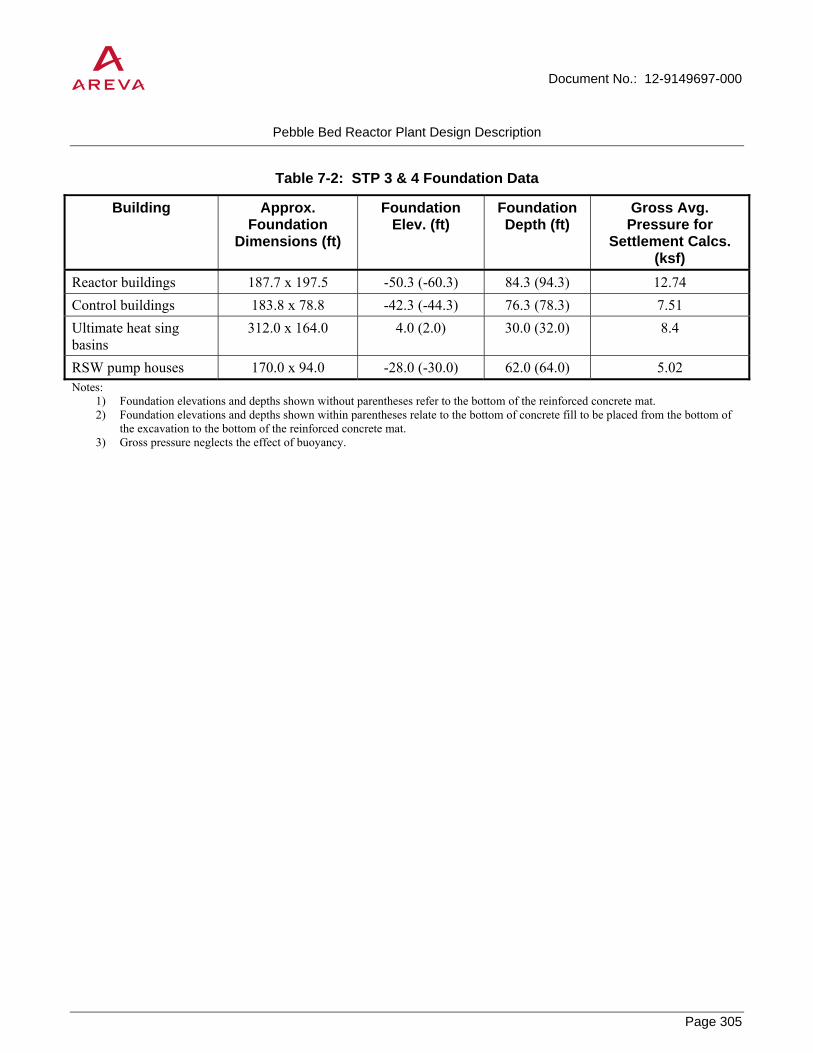
Document No.: 12-9149697-000
Pebble Bed Reactor Plant Design Description
Page 305
PROPRIETARY
Table 7-2: STP 3 & 4 Foundation Data
Building Approx. Foundation
Dimensions (ft)
Foundation Elev. (ft)
Foundation Depth (ft)
Gross Avg. Pressure for
Settlement Calcs. (ksf)
Reactor buildings 187.7 x 197.5 -50.3 (-60.3) 84.3 (94.3) 12.74 Control buildings 183.8 x 78.8 -42.3 (-44.3) 76.3 (78.3) 7.51 Ultimate heat sing basins
312.0 x 164.0 4.0 (2.0) 30.0 (32.0) 8.4
RSW pump houses 170.0 x 94.0 -28.0 (-30.0) 62.0 (64.0) 5.02 Notes:
1) Foundation elevations and depths shown without parentheses refer to the bottom of the reinforced concrete mat. 2) Foundation elevations and depths shown within parentheses relate to the bottom of concrete fill to be placed from the bottom of
the excavation to the bottom of the reinforced concrete mat. 3) Gross pressure neglects the effect of buoyancy.
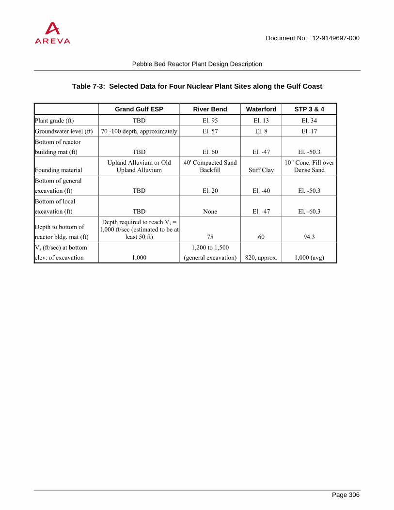
Document No.: 12-9149697-000
Pebble Bed Reactor Plant Design Description
Page 306
PROPRIETARY
Table 7-3: Selected Data for Four Nuclear Plant Sites along the Gulf Coast
Grand Gulf ESP River Bend Waterford STP 3 & 4
Plant grade (ft) TBD El. 95 El. 13 El. 34
Groundwater level (ft) 70 -100 depth, approximately El. 57 El. 8 El. 17
Bottom of reactor building mat (ft) TBD El. 60 El. -47 El. -50.3
Founding material Upland Alluvium or Old
Upland Alluvium 40' Compacted Sand
Backfill Stiff Clay 10 ' Conc. Fill over
Dense Sand
Bottom of general excavation (ft) TBD El. 20 El. -40 El. -50.3
Bottom of local excavation (ft) TBD None El. -47 El. -60.3
Depth to bottom of reactor bldg. mat (ft)
Depth required to reach Vs = 1,000 ft/sec (estimated to be at
least 50 ft) 75 60 94.3
Vs (ft/sec) at bottom elev. of excavation 1,000
1,200 to 1,500 (general excavation) 820, approx. 1,000 (avg)

Document No.: 12-9149697-000
Pebble Bed Reactor Plant Design Description
Page 307
PROPRIETARY
8.0 REFERENCES
1. IAEA-TECDOC-1198, Current Status and Future Development of Modular High Temperature Gas Cooled Reactor Technology, International Atomic Energy Agency, February 2001.
2. IAEA, Status Report 70 – Pebble Bed Modular Reactor (PBMR), International Atomic Energy Agency, updated September 20, 2010.
3. NGNP Industry Alliance white paper, NGNP Project Implementation Strategy, November 2009.
4. NGNP Program Planning Bases for Cost and Schedule Estimate, PLN-2970, December 2011.
5. High Temperature Reactor Modular Plant (HTR-Module) – Safety Analysis Report, August, 1988.
6. Point Design for the AREVA HTR-Module Assessment, AREVA, 12-9152894-000.
7. FZJ-IEK6-1.1.5.2, “Assessment of Transients during Normal Operation”, Dr.-Ing. Kay Nünighoff, Forschungszentrum Jülich, 12/30/2010.
8. NGNP System Requirements Manual, INL/EXT-07-12999 Revision 3, September 10, 2009.
9. Key Design Requirements for the High Temperature Gas-cooled Reactor Nuclear Heat Supply System, INL/EXT-10-19887, September, 2010.
10. Key Pebble Bed Reactor Design Requirements, AREVA, 12-9152036-000.
11. Stone & Webster Engineering Corp, “Turbine Selection Trade Study 4 x 250 MW(t) HTGR Plant Side-By-Side Steel Vessel Concept,” HTGR-85-017, July, 1985.
12. IAEA - ARIS. Status Report 70 - Pebble Bed Modular Reactor. 20 09 2010. http://aris.iaea.org/ARIS/download.cgi?requested_doc=report&doc_id=70&type_of_output=pdf (accessed 12 13, 2010).
13. IAEA. PRIS: Operating Experience, AVR Jeulich. 2010. http://www.iaea.org/cgi-bin/db.page.pl/pris.ophis.htm?country=DE&site=AVR%20JUELICH&units=&refno=4&opyear=1988&link=HOT (accessed 12 31, 2010).
14. IAEA. PRIS: Operating Experience History - THTR-300. 2010. http://www.iaea.org/cgi-bin/db.page.pl/pris.ophis.htm?country=DE&site=THTR-300&units=&refno=19&opyear=1989&link=HOT (accessed 12 31, 2010).
15. International Association of Engineering Insurers. “Maintenance and Overhaul of Steam Turbines.” International Association of Engineering Insurers 38th Annual Conference, IMIA – WGP 42 (05). Moscow, 2005.
16. North American Electric Reliability Corporation (NERC). Generating Availability Report (GAR). Princeton, NJ: NERC, 2009.

Document No.: 12-9149697-000
Pebble Bed Reactor Plant Design Description
Page 308
PROPRIETARY
17. HTR-E, High Temperature Reactor Components and Systems, Catcher Bearings Tests – Past Experience from the German HTR R&D Programme, FZJ.
18. HTRE0206D311, HTR – E AMBs and CBs – Functional requirements, 20/11/2002.
19. BU1 214/02 Rev B, HTR-E Magnetic bearing Concept proposal, Oct 2002.
20. INL/EXT-10-19329, High Temperature Gas-Cooled Reactors Lessons Learned Applicable to the Next Generation Nuclear Plant, J.M. Beck, C.B. Garcia, L.F. Pincock, September 2010.
21. S2M Magnetic Bearings and High Speed Motors Proposes Innovative Solutions for Turboexpanders, http://www.s2m.fr/E/4-APPLICATIONS/offshore.html, accessed 1/31/2011.
22. Flexible Electric Drive, http://www.magnetic-bearings-s2m.com/chap2/flexible-electric-drive.html, accessed 1/31/2011.
23. Mopico, http://www.magnetic-bearings-s2m.com/chap2/mopico.html, accessed 1/31/2011.
24. Dresser-Rand – Dresser-Rand Introduces and In-Line Electric Motor-Driven Compressor, http://investor.dresser-rand.com/releasedetail.cfm?ReleaseID=182847, accessed 1/31/2011.
25. MAN Diesel & Turbo, http://www.google.fr/url?q=http://mandieselturbo.com/files/news/filesof12079/27-50-10-40_Hofim_compressor_e.pdf&sa=U&ei=k1o0TcuKD4vQjAeRloWJBw&ved= 0CBgQFjAFOBQ&usg=AFQjCNHV3trYOEQmlZBc2xkuq3yP-h_Rag, accessed 1/31/2011.
26. GE Oil & Gas Blue-C Subsea Compressor, http://www.google.fr/url?q=http://www.gepower.com/ businesses/ge_oilandgas/en/literature/en/downloads/BlueC.pdf&sa=U&ei=mlU0Td_KIcOQjAe0o83aCg&ved=0CCEQFjAI&usg=AFQjCNEM0j67AmfHNd8mxcg9NOn-WuKcYg, accessed 1/31/2011.
27. Experience Magnetic Bearing Systems from Waukesha Bearings, http://www.waukbearing.com/en-US/systems/experience/, accessed 1/31/2011.
28. NGNP with Hydrogen Production Preconceptual Design Studies Report, AREVA, 12-9051191-001, June 2007.
29. NGNP with Hydrogen Production Preconceptual Design Report, Westinghouse, NGNP-xx-RPT-001, May 2007.
30. AREVA IHX Alternatives Report, AREVA, 12-9076325-001.
31. C. Rodriguez, A. Baxter, “Transmutation of Nuclear Waste Using Gas-Cooled Reactor Technologies,” 8th International Conference on Nuclear Engineering, April 2-6, 2000, Baltimore, MD.
32. L. Lommers, “Advanced Fuel Cycles and Actinide Burning in HTRs and the NGNP,” MIT Symposium on NGNP Goals and Challenges, February 23-24, 2005, Cambridge, MA.
33. NUREG-1840, Safety Evaluation Report for an Early Site Permit (ESP) at the Grand Gulf Site, Docket No. 52-009, April 2006, U.S. Nuclear Regulatory Commission.
34. River Bend Station, Updated Safety Analysis Report, Rev. 10. Gulf States Utilities Company, 1998.

Document No.: 12-9149697-000
Pebble Bed Reactor Plant Design Description
Page 309
PROPRIETARY
35. Waterford Steam Electric Station, Unit 3, Final Safety Analysis Report, Rev. 302. Louisiana Power & Light Co., 2008.
36. South Texas Project 3 & 4, Final Safety Analysis Report, Rev. 4, 2008.