
ARES: An Anti-jamming REinforcement System for 802.11...
12
ARES: An Anti-jamming REinforcement System for 802.11 Networks Konstantinos Pelechrinis Dept. of CS&E UC Riverside ∗ [email protected] Ioannis Broustis Dept. of CS&E UC Riverside [email protected] Srikanth V. Krishnamurthy CS&E, UC Riverside [email protected] Christos Gkantsidis Microsoft Research Cambridge, UK [email protected] ABSTRACT Dense, unmanaged 802.11 deployments tempt saboteurs into launching jamming attacks by injecting malicious interfer- ence. Nowadays, jammers can be portable devices that transmit intermittently at low power in order to conserve energy. In this paper, we first conduct extensive experi- ments on an indoor 802.11 network to assess the ability of two physical layer functions, rate adaptation and power con- trol, in mitigating jamming. In the presence of a jammer we find that: (a) the use of popular rate adaptation algorithms can significantly degrade network performance and, (b) ap- propriate tuning of the carrier sensing threshold allows a transmitter to send packets even when being jammed and enables a receiver capture the desired signal. Based on our findings, we build ARES, an Anti-jamming REinforcement System, which tunes the parameters of rate adaptation and power control to improve the performance in the presence of jammers. ARES ensures that operations under benign conditions are unaffected. To demonstrate the effectiveness and generality of ARES, we evaluate it in three wireless testbeds: (a) an 802.11n WLAN with MIMO nodes, (b) an 802.11a/g mesh network with mobile jammers and (c) an 802.11a WLAN with TCP traffic. We observe that ARES improves the network throughput across all testbeds by up to 150%. Categories and Subject Descriptors C.2.0 [General]: Security and Protection; C.2.3 [Computer Communication Networks]: Network Operations General Terms Design,Experimentation,Measurement,Performance,Security ∗ This work was done partially with support from the US Army Research Office under the Multi-University Research Initiative (MURI) grants W911NF-07-1-0318 and the NSF NeTS:WN / Cyber trust grant 0721941. Permission to make digital or hard copies of all or part of this work for personal or classroom use is granted without fee provided that copies are not made or distributed for profit or commercial advantage and that copies bear this notice and the full citation on the first page. To copy otherwise, to republish, to post on servers or to redistribute to lists, requires prior specific permission and/or a fee. CoNEXT’09, December 1–4, 2009, Rome, Italy. Copyright 2009 ACM 978-1-60558-636-6/09/12 ...$10.00. Keywords IEEE 802.11, Rate Control, Power Control, Jamming 1. INTRODUCTION The widespread proliferation of 802.11 wireless networks makes them an attractive target for saboteurs with jam- ming devices [1, 2, 3, 4]; this makes the defense against such attacks very critical. A jammer transmits electromagnetic energy to hinder legitimate communications on the wireless medium. A jamming attack can cause the following effects in an 802.11 network: (a) Due to carrier sensing, co-channel transmitters defer their packet transmissions for prolonged periods. (b) The jamming signal collides with legitimate packets at receivers. Frequency hopping techniques have been previously proposed for avoiding jammers [5] [6]. Such schemes however, are not effective in scenarios with wide- band jammers [7, 8]. Furthermore, given that 802.11 oper- ates on relatively few frequency channels, multiple jamming devices operating on different channels can significantly hurt performance in spite of using frequency hopping [9]. In this paper, we ask the question: How can legacy 802.11 devices alleviate the effects of a jammer that resides on the same channel used by a legitimate communicating pair, in real time? We address this challenge by developing ARES 1 , a novel measurement driven system, which detects the pres- ence of jammers and invokes rate adaptation and power control strategies to alleviate jamming effects. Clearly, not much can be done to mitigate jammers with unlimited re- sources in terms of transmission power and spectrum effi- ciency. Note however that in a plurality of cases the jamming device can be resource constrained, with capabilities similar to that of the legitimate device 2 . Portable, battery-operated jammers are typically configured to transmit intermittently and sometimes at low power, in order to conserve energy and harm the network for extended periods of time. In addition, misconfiguration of “legitimate” devices can transform them to resource-constrained jammers [3]. In such cases, ARES can effectively fight against the malicious entity, as we dis- cuss later. Our contributions are the following: 1 ARES [pron. “´aris”] was the god of war in Greek mythol- ogy; we choose the name as a symbol of the combat with jammers. 2 We implement a jamming utility on a commodity 802.11 NIC as described in more detail in Section 3. 181
Transcript of ARES: An Anti-jamming REinforcement System for 802.11...

ARES: An Anti-jamming REinforcement Systemfor 802.11 Networks
Konstantinos PelechrinisDept. of CS&EUC Riverside ∗
Ioannis BroustisDept. of CS&EUC Riverside
Srikanth V.Krishnamurthy
CS&E, UC [email protected]
Christos GkantsidisMicrosoft Research
Cambridge, [email protected]
ABSTRACTDense, unmanaged 802.11 deployments tempt saboteurs intolaunching jamming attacks by injecting malicious interfer-ence. Nowadays, jammers can be portable devices thattransmit intermittently at low power in order to conserveenergy. In this paper, we first conduct extensive experi-ments on an indoor 802.11 network to assess the ability oftwo physical layer functions, rate adaptation and power con-trol, in mitigating jamming. In the presence of a jammer wefind that: (a) the use of popular rate adaptation algorithmscan significantly degrade network performance and, (b) ap-propriate tuning of the carrier sensing threshold allows atransmitter to send packets even when being jammed andenables a receiver capture the desired signal. Based on ourfindings, we build ARES, an Anti-jamming REinforcementSystem, which tunes the parameters of rate adaptation andpower control to improve the performance in the presenceof jammers. ARES ensures that operations under benignconditions are unaffected. To demonstrate the effectivenessand generality of ARES, we evaluate it in three wirelesstestbeds: (a) an 802.11n WLAN with MIMO nodes, (b) an802.11a/g mesh network with mobile jammers and (c) an802.11a WLAN with TCP traffic. We observe that ARESimproves the network throughput across all testbeds by upto 150%.
Categories and Subject DescriptorsC.2.0 [General]: Security and Protection; C.2.3 [ComputerCommunication Networks]: Network Operations
General TermsDesign,Experimentation,Measurement,Performance,Security
∗This work was done partially with support from the USArmy Research Office under the Multi-University ResearchInitiative (MURI) grants W911NF-07-1-0318 and the NSFNeTS:WN / Cyber trust grant 0721941.
Permission to make digital or hard copies of all or part of this work forpersonal or classroom use is granted without fee provided that copies arenot made or distributed for profit or commercial advantage and that copiesbear this notice and the full citation on the first page. To copy otherwise, torepublish, to post on servers or to redistribute to lists, requires prior specificpermission and/or a fee.CoNEXT’09, December 1–4, 2009, Rome, Italy.Copyright 2009 ACM 978-1-60558-636-6/09/12 ...$10.00.
KeywordsIEEE 802.11, Rate Control, Power Control, Jamming
1. INTRODUCTIONThe widespread proliferation of 802.11 wireless networks
makes them an attractive target for saboteurs with jam-ming devices [1, 2, 3, 4]; this makes the defense against suchattacks very critical. A jammer transmits electromagneticenergy to hinder legitimate communications on the wirelessmedium. A jamming attack can cause the following effectsin an 802.11 network: (a) Due to carrier sensing, co-channeltransmitters defer their packet transmissions for prolongedperiods. (b) The jamming signal collides with legitimatepackets at receivers. Frequency hopping techniques havebeen previously proposed for avoiding jammers [5] [6]. Suchschemes however, are not effective in scenarios with wide-band jammers [7, 8]. Furthermore, given that 802.11 oper-ates on relatively few frequency channels, multiple jammingdevices operating on different channels can significantly hurtperformance in spite of using frequency hopping [9].
In this paper, we ask the question: How can legacy 802.11devices alleviate the effects of a jammer that resides on thesame channel used by a legitimate communicating pair, inreal time? We address this challenge by developing ARES1,a novel measurement driven system, which detects the pres-ence of jammers and invokes rate adaptation and powercontrol strategies to alleviate jamming effects. Clearly, notmuch can be done to mitigate jammers with unlimited re-sources in terms of transmission power and spectrum effi-ciency. Note however that in a plurality of cases the jammingdevice can be resource constrained, with capabilities similarto that of the legitimate device2. Portable, battery-operatedjammers are typically configured to transmit intermittentlyand sometimes at low power, in order to conserve energy andharm the network for extended periods of time. In addition,misconfiguration of “legitimate” devices can transform themto resource-constrained jammers [3]. In such cases, AREScan effectively fight against the malicious entity, as we dis-cuss later. Our contributions are the following:
1ARES [pron. “aris”] was the god of war in Greek mythol-ogy; we choose the name as a symbol of the combat withjammers.2We implement a jamming utility on a commodity 802.11NIC as described in more detail in Section 3.
181

1. Understanding the impact of jammers in an 802.11network with rate/power control. First, we performan in-depth measurement-based experimental study on ourindoor testbed, to quantify the impact of jamming whenemploying rate and/or power control. To the best of ourknowledge, there are no such studies to date. With ratecontrol, a transmitter can increase or lower its transmissionrate depending on the observed packet delivery ratio (PDR)at the receiver. With power control, nodes may increasetheir transmission powers and/or clear channel assessment(CCA) thresholds [10] in order to increase the probability ofsuccessful packet reception. The design of ARES is drivenby two key experimental observations:
i) Rate adaptation can be counter-productive: In thepresence of a jammer that is active intermittently (and sleepsin between), the use of rate adaptation is not always benefi-cial. We conduct experiments with three popular rate adap-tation algorithms: SampleRate [11], Onoe [12] and AMRR(Adaptive Multi Rate Retry) [13]. With every scheme, weobserve that the use of rate adaptation may work in favorof the jammer. This is because, rate adaptation wastes alarge portion of a jammer’s sleeping time in order to gradu-ally converge to the “best” rate. We analytically determinewhen fixed rate operations may be preferable to the use ofrate adaptation.
ii) Tuning the carrier sense threshold is beneficial:We collect throughput measurements with many differenttransmission powers and CCA thresholds. We find that:(a) In the presence of a jammer, legitimate transmissionswith maximum power could lead to significant benefits, onlywhen operating at low data rates. (b) Increasing the CCAthreshold can allow a transmitter that is being jammed tosend packets and in addition, facilitate the capture of pack-ets in the presence of jamming interference; together, theseeffects can significantly reduce the throughput degradation.2. Designing ARES, a novel anti-jamming system.The above observations drive the design of ARES. ARES pri-marily consists of two modules. The rate control modulechooses between fixed-rate assignment and rate adaptation,based on channel conditions and the jammer characteristics.The primary objective of this module is to effectively utilizethe periods when a jammer is asleep. The power controlmodule adjusts the CCA threshold to facilitate the trans-mission and the reception (capture) of legitimate packetsduring jamming. Care is taken to avoid starvation of nodesdue to the creation of asymmetric links [10]. This module isused to facilitate successful communications while the jam-mer is active. Although rate and power control have beenproposed as interference alleviation techniques, their behav-ior has not been studied in jamming environments. To ourknowledge, our work is the first to conduct such a study.3. Implementing and experimentally validating ARES.We implement and evaluate the modules of ARES on realhardware, thereby making ARES one of the few anti-jammingsystem implementations for 802.11 networks. ARES relieson the existence of an accurate jamming detection mod-ule. It is beyond the scope of our work to design a newdetection scheme, and thus we incorporate a mechanism pro-posed previously in [14]. To demonstrate the effectivenessand generality of our system, we apply it on three differ-ent experimental networks: an 802.11n WLAN with MIMOenabled nodes, an 802.11a/g mesh network with mobile jam-mers, and a static 802.11a WLAN with uplink TCP traffic.Our measurements demonstrate that ARES provides per-
formance benefits in all the three networks; throughput im-provements of up to 150% are observed.
2. BACKGROUND AND RELATED WORKIn this section, first we briefly describe the operations of a
jammer and its attack capabilities. Next, we discuss relevantprevious studies.
Types of Jamming Attacks. Jammers can be distin-guished in terms of their attack strategy; a detailed discus-sion can be found in [14].
Non-stop jamming: Constant jammers continuously emitelectromagnetic energy on a channel. Nowadays, constantjammers are commercially available and easy to obtain [1, 7].While constant jammers emit non-decipherable messages,deceptive jammers transmit seemingly legitimate back-to-back dummy data packets. Hence, they can mislead othernodes and monitoring systems into believing that legitimatetraffic is being sent.
Intermittent Jamming: As the name suggests, thesejammers are active intermittently; the primary goal is toconserve battery life. A random jammer typically alternatesbetween uniformly-distributed jamming and sleeping peri-ods; it jams for Tj seconds and then it sleeps for Ts seconds.A reactive jammer starts emitting energy only if it detectstraffic on the medium. This makes the jammer difficult todetect. However, implementing reactive jammers can be achallenge.
Attackers are motivated into using a random jammer be-cause putting the jammer to sleep intermittently can in-crease its lifetime and decrease the probability of detection[14]. Furthermore, it is the most generalized representationof a jammer; appropriately choosing the sleep times couldturn the jammer into a constant jammer or (with high prob-ability) a reactive jammer. Moreover, reactive jammers arenot easily available since they are harder to implement andrequire special expertise on the part of the attacker.
Related work. Most previous studies employ frequencyhopping to avoid jammers. Frequency hopping, however,cannot alleviate the influence of a wide-band jammer [7, 8],which can effectively jam all the available channels. In ad-dition, recent studies have shown that a few cleverly co-ordinated, narrow-band jammers can practically block theentire spectrum [9]. Thus, ARES does not rely on frequencyhopping. For a set of related studies based on frequencyhopping, please see [5], [6], [15].
Xu et al. [14] develop efficient mechanisms for jammerdetection at the PHY layer (for all the 4 types of jam-mers). However, they do not propose any jamming miti-gation mechanisms. In [16], the same authors suggest thatcompetition strategies, where transceivers adjust their trans-mission powers and/or use error correction codes, might al-leviate jamming effects. However, they neither propose ananti-jamming protocol nor perform evaluations to validatetheir suggestions. Lin and Noubir [17] present an analyti-cal evaluation of the use of cryptographic interleavers withdifferent coding mechanisms to improve the robustness ofwireless LANs. In [18], the authors show that in the ab-sence of error-correction codes (as with 802.11) the jammercan conserve battery power by destroying only a portion ofa legitimate packet. Noubir [19] also proposes the use ofa combination of directional antennae and node-mobility inorder to alleviate jammers. ARES can easily be used in con-junction with directional antennae or with error correctioncodes.
182

3. EXPERIMENTAL SETUPIn this section, we describe our wireless testbed and ex-
perimental methodology.Testbed Description: Our testbed consists of 37 Soekris
net4826 nodes [20], which mount a Debian Linux distribu-tion with kernel v2.6, over NFS. Thirty of these nodes areeach equipped with two miniPCI 802.11a/g WiFi cards, anEMP-8602 6G with Atheros chipset and an Intel-2915. Theother 7 nodes are equipped with one EMP-8602 6G and oneRT2860 card that supports MIMO-based (802.11n) commu-nications. We use the MadWifi driver [21] for the EMP-86026G cards. We have modified the Linux client driver [22] ofthe RT2860 to enable STBC (Space Time Block Coding)support. We use a proprietary version of the ipw2200 AP(access point) and client driver/firmware of the Intel-2915card. With this version we are able to tune the CCA thresh-old parameter.
Experimental Settings and Methodology: We ex-periment with different rate adaptation algorithms in thepresence of random jammers. We also perform experimentswith various transmission powers of jammers and powers/CCAthresholds of legitimate nodes. Our measurements encom-pass an exhaustive set of wireless links, routes of differentlengths, as well as static and mobile jammers. We exam-ine both SISO and MIMO links. We experiment with threemodes of operation: 802.11a/g/n (unless otherwise statedthroughout this paper, our observations are consistent forall three modes of operation). The experiments are per-formed late at night in order to isolate the impact of thejammers by avoiding interference from co-located WLANs.By default, all devices (legitimate nodes and jammers) settheir transmission powers to 18 dBm.
Implementing a random jammer: Our implementa-tion of a jammer is based on a specific configuration (CCA= 0 dBm) and a user space utility that sends broadcastpackets as fast as possible. By setting the CCA thresh-old to such a high value, we force the device to ignore alllegitimate 802.11 signals even after carrier sensing; packetsarrive at the jammer’s circuitry with powers less than 0 dBm(even if the distances between the jammer and the legitimatetransceivers are very small). We implement a random jam-mer but by setting the sleep time to zero, it can function asa constant jammer. We use a set of 4 nodes as jammers onour testbed; these are equipped with Intel-2915 cards whichallow CCA tuning.
Traffic characteristics: We utilize the iperf measure-ment tool to generate UDP data traffic among legitimatenodes; the packet size is 1500 bytes. The duration of eachexperiment is 1 hour. For each experiment, we first enableiperf traffic between legitimate nodes, and subsequently, weactivate the jammer(s). We consider both mesh and WLANconnectivity. We experiment with different jammer distri-butions, namely: (a) frequent jammers, which are active al-most all of the time, (b) rare jammers, which spend most oftheir time sleeping, and (c) balanced jammers that have sim-ilar average jamming and sleeping times. We have disabledRTS/CTS message exchange throughout our experiments (acommon design decision in practice [23]).
4. DERIVING SYSTEM GUIDELINESIn this section, we describe our experiments towards un-
derstanding the behavioral trends of power and rate adap-tation techniques, in the presence of jammer(s). Our goal isto determine if there are properties that can be exploited in
order to alleviate jamming effects. We perform experimentson both single-hop and multi-hop configurations.
4.1 Rate Adaptation in Jamming EnvironmentsRate adaptation algorithms are utilized to select an ap-
propriate transmission rate as per the current channel con-ditions. As interference levels increase, lower data rates aredynamically chosen. Since legitimate nodes consider jam-mers as interferers, rate adaptation will reduce the trans-mission rate on legitimate links while jammers are active.Hence, one could potentially argue that rate control on le-gitimate links increases reliability by reducing rate and thus,can provide throughput benefits in jamming environments.
To examine the validity of this argument, we experimentwith three different, popular rate adaptation algorithms,SampleRate [11], AMRR [13] and Onoe [12]. These algo-rithms are already implemented on the MadWifi driver thatwe use. For simplicity, we first consider a balanced randomjammer, which selects the sleep duration from a uniform dis-tribution U [1, 8] and the jamming duration from U [1, 5] (inseconds).
Details on the experimental process: We perform ex-periments with both single-hop and multi-hop configura-tions. In each experiment, we first load the particular rate-control Linux-kernel module (SampleRate, AMRR or Onoe)on the wireless cards of legitimate nodes. We initiate datatraffic between the nodes and activate the jammer after arandom time. We collect throughput measurements on eachdata link once every 500 msec. We use the following termi-nology:
1) Fixed transmission rate Rf : This is the nominal trans-mission rate configured on the wireless card.
2) Saturated rate Rs: It is the rate achieved when Rf ischosen to be the rate on the wireless card. In order to com-pute Rs, for a given Rf , we consider links where the packetdelivery ratio (PDR) is 100 % for the particular setting ofRf ; we then measure the rate achieved in practice. We no-tice that for lower values of Rf , the specified rate is actuallyachieved on such links. However, for higher values of Rf (asan example Rf = 54 Mbps), the achieved data rate is muchlower; this has been observed in other work e.g. [24]. Table1 contains a mapping, derived from measurements on ourtestbed, between Rf and Rs.
3) Application data rate Ra: This is the rate at which theapplication generates data.
Rf 6 9 12 18 24 36 48 54Rs 6 9 12 18 24 26 27 27
Table 1: The saturated-throughput matrix in Mbps.
It is difficult (if not impossible) to a priori determine thebest fixed rate on a link. Given this, we set:
Rf = {min Rf : Rf ≥ Ra},which is the maximum rate that is required by the applica-tion (we discuss the implications of this choice later). Ourkey observations are summarized below:
• Rate adaptation algorithms perform poorly onhigh-quality links due to the long times thatthey incur for converging to the appropriatehigh rate.
• On lossless links, the fixed rate Rf is better,while rate adaptation is beneficial on lossy links.
183

We defer defining what constitute lossless or lossy links tolater; conceptually, we consider lossless links to be thoselinks that can achieve higher long-term throughput using afixed transmission rate Rf , rather than by applying rateadaptation.
4.1.1 Single-hop ConfigurationsOur experiments with one-hop connectivity involve 80 sets
of sender-receiver pairs and one jammer per pair. We imposethat a jammer interferes with one link at a time and thatthe legitimate data links do not interfere with each other.Thus, we perform 20 different sets of experiments, with 4isolated data links and 4 jammers in each experiment.
Rate adaptation consumes a significant part of thejammer’s sleep time, to converge to the appropriaterate: As soon as the jammer“goes to sleep”, the link qualityimproves and thus, the rate control algorithm starts increas-ing the rate progressively. However, since the purpose of ajamming attack is to corrupt as many transmissions as pos-sible, the jammer will typically not sleep for a long time. Insuch a case, the sleep duration of the jammer will not beenough for the rate control to reach the highest rate possi-ble. To illustrate this we choose two links on our testbed,one that can support 12 Mbps and the other that can sup-port 54 Mbps. Figure 1 depicts the results. We observethat (a) irrespective of whether SampleRate or a fixed ratestrategy is used, during jamming the throughput drops tovalues close to zero since the jammer blocks the medium forthe sender, and (b) the throughput achieved with SampleR-ate is quite low, and much lower than if we fix the rate tothe constant value of 12 Mbps. Note that we have observedthe same behavior with AMRR and Onoe.
Fixed rate assignment outperforms rate adapta-tion on lossless links: As alluded to above, in order tofind the best rate on a link after a period where there is nothroughput due to a jammer, the rate adaptation mecha-nisms gradually increase the rate, invoking transmissions atall the lower rates interim, until the best rate is reached.For links that can inherently support high rates, this pro-cess might consume the sleep period of the jammer (as sug-gested by the results in Figure 1). If the best rate for a linkwas known a priori, at the instance that the jammer goes tosleep, transmissions may be invoked at that rate. This wouldutilize the sleep period of the jammer more effectively. Asobserved in Figure 2, the throughputs achieved with fixedrate assignment are much higher than those achieved withrate adaptation on such links.Determining the right transmission rate policy:
Implications of setting Rf = {min Rf : Rf ≥ Ra}:Since the application does not require the link to sustain ahigher rate, the highest throughput for that application rateis reached either with this choice of Rf or with some ratethat is lower than Ra. If the rate adaptation algorithm con-verges to a rate that results in a throughput that is higherthan with the chosen Rf , then the adaptive rate strategyshould be used. If instead, during the jammer’s sleep pe-riod, the rate adaptation technique is unable to converge tosuch a rate, the fixed rate strategy is better.
Analytically determining the right rate: In order to deter-mine whether it is better to use a fixed or an adaptive-rateapproach for a given link, we perform an analysis based onthe following parameters:
1. The distribution of the jammer’s active and sleep pe-riods (we call this the jammer’s distribution).
2. The application data rate, Ra.
3. The performance metric on the considered legitimatelink, i.e., PDR, link throughput, etc.
4. The rate adaptation scheme that is employed, i.e., Onoe,SampleRate, etc. The key scheme-specific factor is thetransition time from a lower rate to the next higherrate, under conducive conditions.
5. The effectiveness of the jammer F , measured by theachievable throughput while the jammer is on. Thelower the throughput, the more effective the jammer.
Let us suppose that the expected sleeping duration of thejammer during a cycle, is given by E[ts] and the expectedperiod for which it is active, by E[tj ]. The expected durationof a cycle is then E[ts]+E[tj ]. As an example, if the jammerpicks its sleeping period from a uniform distribution U [a, b]and its jamming period from U [c, d], E[ts] and E[tj ] areequal to b+a
2and d+c
2, respectively. For simplicity let us
assume that the link-quality metric employed3 is the PDR.With application data rate Ra and fixed transmission rateRf , the throughput achieved during a jammer’s cycle is:
Tfixed =E[ts]
E[ts] + E[tj ]· PDRf ·Rs +
E[tj ]
E[ts] + E[tj ]· F, (1)
where PDRf is the PDR of the link at rate Rf . Recall thatthe rate achieved in practice with a specified rate Rf is Rs.To compute the throughput with rate adaptation, we pro-ceed as follows. Let us assume that x(F, Rs) corresponds tothe convergence time of the rate adaptation algorithm (spe-cific to the chosen algorithm). We consider the followingtwo cases.1) x(F, Rs) < E[ts]. This case holds when the jammer’ssleep duration is sufficient (on average) for the rate controlalgorithm to converge to the best rate Rs. In this scenario,the achievable throughput is:
Tadapt =
[E[ts] − x(Rs)]·Rs +XRi
y(Ri)·Ri + E[tj ] · F
E[ts] + E[tj ],
where Ri ∈ S, S being the set of all intermediate rates fromF to Rs. y(Ri) is the time that the rate control algorithmspends at the corresponding rate Ri. The values of y(Ri) arespecific to the implementation of the rate control algorithm.Note that x(F, Rs) can be easily computed from y(Ri) byadding all the individual durations for the rates belongingto the set S.2) x(F, Rs) ≥ E[ts]. In this scenario, the average sleeptime of the jammer is insufficient for the rate control algo-rithm to converge to the desired rate. When the jammerwakes up, the rate will again drop due to increased interfer-ence. Here, the throughput that can be achieved during ajammer’s cycle is:
Tadapt =
nXi=1
y(Ri)·Ri+
"E[ts]−
nXi=1
y(Ri)
#·Rn+1 + E[tj ]·F
E[ts] + E[tj ]
where n = max{k :
kXi=1
y(Ri) ≤ E[ts] }.3Our analysis can be modified to adopt any other link-quality metric.
184

0
2
4
6
8
10
12
14
0 10 20 30 40 50 60
Thr
ough
put (
Mbp
s)
Time (sec)
Fixed rate 12MbpsSample rate 12Mbps
0
5
10
15
20
25
30
35
0 10 20 30 40 50 60
Thr
ough
put (
Mbp
s)
Time (sec)
Fixed rate 54MbpsSample rate 54Mbps
Figure 1: Rate adaptation algorithms may not find the bestrate during the sleep period of the jammer. We show cases forRa = 12 Mbps (left) and Ra = 54 Mbps (right).
0
5
10
15
20
25
54483624181296
Ave
rage
Thr
ough
put (
Mbp
s)
Rate(Mbps)
Fixed RateSample Rate
AMRRONOE
Figure 2: Fixed rates outperform rateadaptation for high-quality links, underrandom jamming. (Ra = Rf)
Based on the above analysis, we define a link to be lossy,when Tfixed ≤ Tadapt; the links on which Tfixed > Tadapt
are classified as lossless links. Clearly for lossy links itis better to use the rate adaptation algorithm. The anal-ysis can be used to compute PDRTH
f , a threshold valueof PDRf below which, a rate adaptation strategy performsbetter than the fixed rate approach. In particular, by settingTfixed = Tadapt and solving this equation, one can computePDRTH
f . Based on this, a decision can be made on whetherto enable rate adaptation or use fixed-rate assignment. Ifthe observed PDR is larger than the computed threshold,fixed rate should be used; otherwise, rate adaptation shouldbe used.
Validation of our analysis: In order to validate ouranalysis, we measure PDRTH
f on 80 different links in thepresence of a balanced jammer. We then compare themagainst the PDRTH
f values computed with our analysis.Note here that the analysis itself depends on measured val-ues of certain quantities (such as the jammer distributionand the function y(Ri)). In this experiment, we consider theSampleRate algorithm, and measure the values of x(F, Rs)and y(Ri). The jammer’s sleep time follows U [0, 4] and thejamming time follows U [1, 6]. Figure 3 plots the values offunction y for different values of Rf .
In Table 2, we compare the theoretically computed PDRthresholds with the ones measured on our testbed, for var-ious values of Rf . We observe that the PDRf thresholdscomputed with our analysis are very similar to the ones mea-sured on our testbed. There are slight discrepancies sinceour analysis is based on using measured average values whichmay change to some extent over time. We wish to stress thatwhile we verify our analysis assuming that the jammer is ac-tive and idle for uniformly distributed periods of time, ouranalysis depends only on expected values and is thereforevalid for other jammer distributions. Finally, Figure 4 showsthe advantage of using a fixed rate approach over SampleR-ate for various PDR values and with Rf = 54 Mbps. Weobserve that SampleRate provides higher throughput onlyfor very low PDR values.
Next, we consider two extreme cases of jamming: frequentand rare jammers (see section 3). The distributions that weuse in our experiments for these jammers are shown in Table3. Note that by choosing the jammer’s sleeping and jammingtime from distributions like that of the frequent jammer, weessentially construct a constant jammer. With frequent jam-mers, the difference in the performance between fixed rateassignment and rate adaptation is larger, while for a rarejammer it is smaller. This is because with rare jamming,
Rf Measured PDRTHf Analytical PDRTH
f
6 0.82 0.839 0.52 0.5512 0.40 0.4118 0.26 0.2724 0.19 0.2136 0.19 0.2048 0.17 0.18554 0.15 0.185
Table 2: PDRf thresholds
rate adaptation has more time to converge and therefore of-ten succeeds in achieving the highest rate possible; one ob-serves the opposite effect when we have a frequent jammer.The results are plotted in Figures 5 and 6.
- Sleep time (sec) Jamming time (sec)Balanced U[1,8] U[1,5]
Rare U[1,5] U[1,2]Frequent U[1,2] U[1,15]
Table 3: The jamming distributions that we use inour experiments.
4.1.2 Random Jamming in Multi-hop TopologiesNext, we examine the impact of a random jammer on the
end-to-end throughput of a multi-hop path. We experimentwith 15 different routes on our testbed. We fix static routesof various lengths (from 2 to 4 links per route) utilizing theroute Unix tool in order to modify the routing tables ofnodes. We place a jammer such that it affects one or morelinks. Along each route, links that are not affected by thejammer consistently use a rate adaptation algorithm. Onthe links that are subject to jamming, our analysis dictatesthe decision on whether to use fixed or adaptive rate assign-ment. We measure the end-to-end throughput on the route.We show our results for routes on which, in the absence ofa jammer, end-to-end throughput of 6 and 12 Mbps was ob-served. From Figure 7 we see that the behavior with rateadaptation on multi-hop routes, in the presence of a randomjammer, is the same as that on a single-hop link. In partic-ular, with low data rates, a sufficiently high PDR has to besustained over the route, in order for a fixed rate approachto perform better than rate adaptation. On the other hand,when routes support high data rates, fixing the rate on theindividual links (that are affected by the jammer) as per ouranalytical framework, provides higher benefits.
185

0
5
10
15
20
25
30
0 2 4 6 8 10 12 14
Rat
e
Time(sec)
6Mbps9Mbps
12Mbps18Mbps24Mbps36Mbps48Mbps54Mbps
Figure 3: Measured conver-gence times of the MadWifiSampleRate algorithm, for thedifferent application data rates.
-5
0
5
10
15
0 0.2 0.4 0.6 0.8 1
Thr
ough
put g
ain
(Mbp
s)
PDR
Figure 4: Throughput gain offixed rate Vs. SampleRate,for various link qualities andfor application data rate of 54Mbps.
0
5
10
15
20
25
30
54483624181296
Ave
rage
Thr
ough
put (
Mbp
s)
Rate(Mbps)
Fixed RateSample Rate
Figure 5: The performancewith rare jammers is alignedwith our observations for thecase with balanced jammers.(Ra = Rf)
0
1
2
3
4
5
6
7
8
54483624181296
Ave
rage
Thr
ough
put (
Mbp
s)
Rate(Mbps)
Fixed RateSample Rate
Figure 6: Fixed rate improvesthe performance more thanrate adaptation at high rates,with frequent jammers. (Ra =Rf)
0
1
2
3
4
5
126
Ave
rage
Thr
ough
put (
Mbp
s)
Rate(Mbps)
Fixed RateSample Rate
Figure 7: Rate adaptationpresents the same behaviorin multihop links; it provideslower throughput at high rates.
0
0.2
0.4
0.6
0.8
1
(18,5)(18,18)
Thr
ough
put (
%)
sust
aine
d
(PL dBm,PJ dBm)
6Mbps54Mbps
Figure 8: Percentage of theisolated throughput, for vari-ous PL and PJ combinations,for two different transmissionrates.
Choosing the right policy in practice: To summa-rize our findings, our analysis demonstrates that using afixed rate may be attractive on lossless links while it wouldbe better to use rate adaptation on lossy links. However,as discussed, determining when to use one over the otherin real time during system operations is difficult; the de-termination requires the knowledge of x(F, Rs), y(Ri) andestimates of how often the jammer is active/asleep, on av-erage. Thus, we choose a simpler practical approach thatwe call MRC for Markovian Rate Control. We will describeMRC in detail later (in section 5) but in a nutshell, MRCinduces memory into the system and keeps track of the feasi-ble rates during benign jamming-free periods; as soon as thejammer goes to sleep, legitimate transmissions are invokedat the most recent rate used during the previous sleeping cy-cle of the jammer. We also perform offline measurements bydirectly using our analytical formulation (with knowledge ofthe aforementioned parameters); these measurements serveas benchmarks for evaluating the efficacy of MRC (discussedin section 6).
4.2 Performance of Power Control in the Pres-ence of Random Jamming
Next, we examine whether tuning power levels can helpcope with the interference injected by a jammer. If we con-sider a single legitimate data link and a jammer, increment-ing the transmission power on the data link should increasethe SINR (signal-to-interference plus noise ratio) of the re-
ceived data packets. Thus, one could argue that increasingthe transmission power is always beneficial in jamming en-vironments [17].
We vary the transmission powers of both the jammer andlegitimate transceiver, as well as the CCA threshold of thelatter. Note that the jammer’s transmission distribution isnot very relevant in this part of our study. Our expectationis that tuning the power of legitimate transceivers will pro-vide benefits while the jammer is active. In other words,one can expect that the benefits from power controlwill be similar with any type of jammer. We define thefollowing:
• RSSIT R : The RSSI of the signal of the legitimatetransmitter at its receiver.
• RSSIRT : The RSSI of the signal in the reverse direc-tion (the receiver is now the transmitter).
• RSSIJT and RSSIJR : The RSSI values of the jam-ming signal at the legitimate transmitter and receiver,respectively.
• RSSIJ : The minimum of {RSSIJT , RSSIJR}.
• PL and CCAL : The transmission power and the CCAthreshold at legitimate transceivers.
• PJ : The transmission power of the jammer.
186
Our main observations are the following:
• Mitigating jamming effects by incrementing PL
is viable at low data rates. It is extremely dif-ficult to overcome the jamming interference athigh rates, simply with power adaptation.
• Increasing CCAL restores (in most cases) theisolated throughput (the throughput achievedin the absence of jammers).
We present our experiments and the interpretations thereof,in what follows.
4.2.1 Increasing PL to cope with jamming interfer-ence
Increasing PL will increase the SINR and one might expectthat this would reduce the impact of jamming interferenceon the throughput. In our experiments we quantify the gainsfrom employing such a “brute-force” approach.
Details on the experimental process: We perform mea-surements on 80 different links and with 4 jammers. We con-sider different fixed values for PJ (from 1 dBm to 18 dBm).For each of these values we vary PL between 1 and 18 dBmand observe the throughput in the presence of the jammer,for all possible fixed transmission rates. For each chosen pairof values {PL, PJ}, we run 60-minute repeated experimentsand collect a new throughput measurement once every 0.5seconds. Both end-nodes of a legitimate link use the sametransmission power.
The combination of high PL and low data ratehelps mitigate the impact of low-power jammers.We experiment with many different locations of the jam-mers. Our measurements indicate that when high transmis-sion rates are used, increasing PL does not help alleviatethe impact of jammers. Sample results are depicted in Fig-ure 8. In this figure, we plot the percentage of the isolatedthroughput achieved in the presence of jamming, for two rep-resentative combinations of PL and PJ and for 2 differentrates. In our experiments on the 80 considered links, therewere no links where incrementing PL increased the through-put at high data rates, even with very low jamming powers.While there could exist cases where incrementing PL couldyield benefits at high rates, this was not observed. In con-trast, we observe that with low data rates and when PJ islow, data links can overcome jamming to a large extent byincreasing PL. Figure 9 depicts another representative sub-set of our measurement results where all legitimate nodesuse PL=18 dBm, while PJ is varied between 1 and 18 dBm.We observe that the combination of high PL with low datarate helps overcome the impact of jamming, when PJ is low.Note also that when PJ is high, it is extremely difficult toachieve high average throughput.
The above observations can be explained by taking a care-ful look at the following two cases:
Strong jammer: Let us consider a jammer such thatRSSIJ > CCAL. This can result in two effects: (a) Thesender will sense that the medium is constantly busy andwill defer its packet transmissions for prolonged periods oftime. (b) The signals of both the sender and the jammer willarrive at the receiver with RSSI values higher than CCAL.This will result in a packet collision at the receiver. In bothcases, the throughput is degraded. Our measurements showthat it is not possible to mitigate strong jammers simply byincreasing PL.
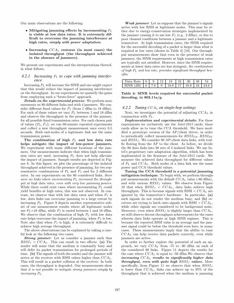
Weak jammer: Let us suppose that the jammer’s signalsarrive with low RSSI at legitimate nodes. This may be ei-ther due to energy-conservation strategies implemented bythe jammer causing it to use low PJ (e.g., 2 dBm), or due topoor channel conditions between a jammer and a legitimatetransceiver. At high transmission rates, the SINR requiredfor the successful decoding of a packet is larger than what isrequired at low rates (shown in Table 4) [10]. Our through-put measurements show that even in the presence of weakjammers, the SINR requirements at high transmission ratesare typically not satisfied. However, since the SINR require-ments at lower data rates are less stringent, the combinationof high PL and low rate, provides significant throughput ben-efits.
Data Rate 6 9 12 18 24 36 48 54SINR (dB) 6 7.8 9 10.8 17 18.8 24 24.6
Table 4: SINR levels required for successful packetdecoding, in 802.11a/g.
4.2.2 Tuning CCAL on single-hop settingsNext, we investigate the potential of adjusting CCAL in
conjunction with PL.Implementation and experimental details: For these
experiments we exclusively use the Intel-2915 cards; thesecards allow us to tune the CCA threshold. We have mod-ified a prototype version of the AP/client driver, in orderto periodically collect measurements for RSSITR, RSSIRT
and RSSIJ . We consider 80 AP-client data links, with traf-fic flowing from the AP to the client. As before, we dividethe 80 data links into 20 sets of 4 isolated links. We use In-tel’s proprietary rate adaptation algorithm, which has beenimplemented in the firmware of the Intel-2915 cards. Wemeasure the achieved data throughput for different valuesof PL and CCAL. Both nodes of a data link use the samepower and CCA threshold values.
Tuning the CCA threshold is a potential jammingmitigation technique. To begin with, we perform through-put measurements with the default CCAL value (-80 dBm),and with various RSSIJ values. We observe from Figure10 that when RSSIJ < CCAL, data links achieve highthroughput. This is because signals with RSSI < CCAL areignored by the transceiver’s hardware. In particular, (a)such signals do not render the medium busy, and (b) re-ceivers are trying to latch onto signals with RSSI > CCAL,while other signals are considered to be background noise.Moreover, even when RSSIJ is slightly larger than CCAL,we still observe decent throughput achievements for the caseswherein data links operate at high SINR regimes. This isbecause the reported RSSI value is an average and the jam-mer signal could be below the threshold even here, in manycases. These measurements imply that the ability to tuneCCAL can help receive data packets correctly, even whilejammers are active.
In order to further explore the potential of such an ap-proach, we vary CCAL from -75 to -30 dBm on each ofthe considered 80 links. Figure 11 depicts the results forthe case where CCAL is equal to -50 dBm.We observe thatincreasing CCAL results in significantly higher datathroughput, even with quite high RSSIJ values. Morespecifically, from Figure 11 we observe that when RSSIJ
is lower than CCAL, links can achieve up to 95% of thethroughput that is achieved when the medium is jamming
187

0
0.2
0.4
0.6
0.8
1
0 2 4 6 8 10 12 14 16 18
Thr
ough
put (
%)
PJ (dBm)
6 Mbps9 Mbps
12 Mbps18 Mbps
24 Mbps36 Mbps48 Mbps54 Mbps
Figure 9: Percentage of the iso-lated throughput in the pres-ence of a balanced jammer forvarious PJ and PJ values anddata rates.
Figure 10: Percentage of theisolated throughput in thepresence of a balanced jammerVs. RSSIJ , for CCAL= –80dBm.
Figure 11: Percentage of theisolated throughput, for vari-ous RSSIJ values, and for CCAL
= –50 dBm.
0
0.2
0.4
0.6
0.8
1
-80 -75 -70 -65 -60 -55 -50 -45 -40
Thr
ough
put (
%)
CCA(dBm)
PL 20dBmPL 15dBmPL 10dBmPL 05dBm
Figure 12: Percentage of theisolated throughput, for vari-ous CCAL values and various PL
values. PJ = 20 dBm.
0
0.2
0.4
0.6
0.8
1
-40-80
Thr
ough
put (
%)
CCA(dBm)
Figure 13: Careful CCA adap-tation significantly improvesthe end-to-end throughputalong a route.
0
5
10
15
20
25
54483624181296
Ave
rage
Thr
ough
put (
Mbp
s)
Rate(Mbps)
Fixed RateSample Rate
MRC with K=3MRC with K=30
Figure 14: MRC outperformscurrent rate adaptation algo-rithms, especially for high val-ues of K.
free. When RSSIJ ≈ CCAL, data links still achieve up to70% of the jamming-free throughput (capture of data pack-ets is still possible to a significant extent). As one mightexpect, if RSSIJ � CCAL, there are no performance ben-efits.
Our observations also hold in some scenarios where, PJ >PL. Figure 12 presents the results from one such scenario.We observe that appropriate CCA settings can allow le-gitimate nodes to exchange traffic effectively, even whenPJ � PL. This is possible if the link conditions between thejammer and the legitimate transceivers are poor and resultin low RSSIJ . Note here that one cannot increase CCAL
to arbitrarily high values on legitimate nodes. Doing so islikely to compromise connectivity between nodes or degradethe throughput due to failure of capturing packets as seenin Figure 12 for PL = 5dBm and PL = 10dBm.
4.2.3 Tuning CCAL in multi-hop configurationsWe perform experiments with various CCA thresholds
along a route. Previous studies have shown that in orderto avoid starvation due to asymmetric links, the transmis-sion power and the CCA threshold need to be jointly tunedfor all nodes of the same connected (sub)network [10]. Inparticular, the product C = PL · CCAL must be the samefor all nodes. Given this, we ensure that C is the same forall nodes that are part of a route. In particular, we set PL
to be equal to the maximum possible value of 20 dBm on allnodes of a route; for each run, CCAL is therefore set to bethe same on all of the nodes on the route. Throughout ourexperiments with multi-hop traffic, nodes on one route donot interfere with nodes that are on other routes. In scenar-ios where nodes belonging to different routes interfere with
each other, if all nodes use the same PL, their CCAL valuesmust be the same [10], [25]. However, we did not experimentwith such scenarios given that our objective is to isolate theimpact of a jammer and not to examine interference betweencoexisting sessions in a network.
We experiment with the same multi-hop settings as insection 4.1.2. Figure 13 presents the results observed onone of our routes. We observe that careful CCA tuning canprovide significant average end-to-end throughput benefitsalong a route.
5. DESIGNING ARESIn this section, we design our system ARES based on the
observations from the previous section. ARES is composedof two main modules: (a) a rate module that chooses be-tween fixed or adaptive-rate assignment, and (b) a powercontrol module that facilitates appropriate CCA tuning onlegitimate nodes.
Rate Module in ARES: As discussed in section 4.1, ourexperiments with three popular rate adaptation algorithmsshow that the convergence time of the algorithms affects thelink performance in random-jamming environments. Thisconvergence time is largely implementation specific. As anexample, our experiments with both SampleRate and Onoeshow that in many cases it takes more than 10 sec for bothalgorithms to converge to the“best”rate; [26] reports similarobservations. The rate module in ARES decides on whethera fixed or an adaptive-rate approach should be applied.
MRC: Markovian Rate Control: MRC is an algorithm–patch that can be implemented on top of any rate controlalgorithm. MRC is motivated by our analysis in section 4.
188

However, as discussed earlier, it does not directly apply theanalysis, since this would require extensive offline measure-ments (the collection of which can be time-consuming) andestimates of the jammer active and sleep periods. The keyidea that drives MRC is that a rate adaptation algorithmneed not examine the performance at all the transmissionrates during the sleeping period of the jammer. The algo-rithm simply needs to remember the previously used trans-mission rate, and use it as soon as the jammer goes to sleep.Simply put, MRC introduces memory into the system. Thesystem keeps track of past transmission rates and hops tothe stored highest-rate state as soon as the jammer goes tosleep. Since the channel conditions may also change dueto the variability in the environment, MRC invokes the re-scanning of all rates periodically, once every K consecutivesleeping/jamming cycles. When K = 1 we do not expectto have any benefits, since the scanning takes place in eachcycle.
Note here that the appropriate value of K depends on theenvironment and the sleep and active periods of the jammer.One could adaptively tune the K value. As an example,an additive increase additive decrease strategy may be usedwhere one would increase the value of K until a degradationis seen. The K value would then be decreased. The im-plementation of such a strategy is beyond the scope of thispaper and will be considered in the future.
Implementation details of MRC: The implementation (a)keeps track of the highest transmission rate used over a be-nign time period (when the jammer is asleep) and, (b) ap-plies this rate immediately upon the detection of the nexttransition from the jammer’s active period to the sleepingperiod.
Figure 14 presents a set of measurements with MRC, withintermittent SampleRate invocations (once every K cycles)for K = {3, 30}. We observe that MRC outperforms pureSampleRate in jamming environments, especially with largervalues of K. With small K, the rate adaptation algorithmis invoked often and this reduces the achieved benefits. Fur-thermore, MRC provides throughput that is close to themaximum achievable on the link (which may be either withfixed or adaptive rate, depending on whether the link is lossyor lossless).
Power Control Module in ARES: As discussed in sec-tion 4.2, increasing PL is beneficial at low rates; while athigh rates this is not particularly useful, it does not hurteither. Since our goal in this paper is to propose methodsfor overcoming the effects of jamming (and not legitimate)interference, we impose the use of the maximum PL by allnodes in the presence of jammers. The design of a powercontrol mechanism that in addition takes into account theimposed legitimate interference (due to high PL) is beyondthe scope of this paper.
More significantly, our power control module overcomesjamming interference by adaptively tuning CCAL. Themodule requires the following inputs on each link:
• The values of RSSITR, RSSIRT , RSSIJR, and RSSIJT .These values can be easily observed in real time.
• An estimation for the shadow fading variation of thechannel, Δ. Due to shadow fading, the above RSSIvalues can occasionally vary by Δ. The value of Δ isdependent on the environment of deployment. One canperform offline measurements and configure the valueof Δ in ARES.
We determine the variations in RSSI measurements via ex-periments on a large set of links. The measurements indicatethat Δ is approximately 5 dB for our testbed (a less con-servative value than what is reported in [27]). The value ofCCAL has to be at least Δ dB lower than both RSSITR
and RSSIRT , to guarantee connectivity at all times. Hence,ARES sets:
CCAL = min(RSSITR, RSSIRT ) − Δ, if
max(RSSIJT ,RSSIJR)≤min(RSSITR,RSSIRT) − Δ.
Otherwise, CCAL is not changed4. This ensures that legiti-mate nodes are always connected, while the jammer’s signalis ignored to the extent possible. Our experiments indicatethat, especially if
max(RSSIJT ,RSSIJR)≤min(RSSITR,RSSIRT) − 2Δ,
the data link can operate as if it is jamming-free.In order to avoid starvation effects, the tuning of the CCA
threshold should be performed only when nodes that par-ticipate in power control belong to the same network [25].Unless collocated networks cooperate in jointly tuning theirCCA (as per our scheme), our power control module willnot be used. Note that when jamming attacks become moreprevalent, cooperation between coexisting networks may beessential in order to fight the attackers. Hence, in such casescollocated networks can have an agreement to jointly in-crease the CCA thresholds when there is a jammer.
Implementation details: Our power control algorithmcan be applied in a centralized manner by having all le-gitimate nodes report the required RSSI values to a centralserver. The central server then applies the same CCAL
value to all nodes (of the same connected network). Thechosen CCAL is the highest possible CCA threshold thatguarantees connectivity between legitimate nodes. This re-porting requires trivial modifications on the wireless drivers.We have implemented a centralized functionality when ournetwork is configured as a multi-hop wireless mesh.
In a distributed setting, our algorithm is applicable aslong as legitimate nodes are able to exchange RSSI infor-mation. Each node can then independently determine theCCAL value. To demonstrate its viability, we implementand test a distributed version of the power control modulein a 802.11a/g WLAN configuration. In particular, we mod-ify the Intel prototype AP driver, by adding an extra field inthe “Beacon” template. This new field contains a matrix ofRSSI values of neighboring jammers and legitimate nodes.We enable the decoding of received beacons in the AP driver(they do not read these by default). Assuming that a jam-mer imposes almost the same amount of interference on alldevices (AP and clients) within a cell, the AP of the celldetermines the final CCAL after a series of iterations in amanner very similar to the approaches in [25], [10].
Combining the modules to form ARES: We combineour rate and power control modules to construct ARES asshown in Figure 15. The goal of ARES is to apply the in-dividual modules as appropriate, once the jammers are de-tected. For the latter, ARES relies on already existing jam-ming detection schemes and inherits their accuracy. For ex-ample, the mechanism that was proposed in [14] can be used;this functionality performs a consistency check between the
4We choose not to tune CCAL, unless we are certain thatit can help alleviate jamming interference.
189

Figure 15: ARES: our Anti-jamming Reinforcement System.
instantaneous PDR and RSSI values. If the PDR is ex-tremely low while the RSSI is much higher than the defaultCCAL, the node is considered to be jammed. We want toreiterate, that it is beyond the scope of our work to designa new, even more accurate, detection scheme.
ARES applies the power control module first, since withthis module, the impact of the jammer(s) could be com-pletely overcome. If the receiver is able to capture and de-code all packets in spite of the jammer’s transmissions, nofurther actions are required. Note that even if CCAL >RSSIJ , the jammer can still affect the link performance.This is because with CCA tuning the jamming signal’s poweris added to the noise power. Hence, even though the through-put may increase, the link may not achieve the “jamming-free performance” while the jammer is active. If the jammerstill has an effect on the network performance after tuningCCAL, (or if CCA tuning is infeasible due to the presence ofcollocated uncooperative networks) ARES enables the ratemodule. Note that the two modules can operate indepen-dently and the system can bypass any of them in case thehardware/software does not support the specific functional-ity.
6. EVALUATING OUR SYSTEMWe first evaluate ARES by examining its performance in
three different networks: a MIMO-based WLAN, an 802.11mesh network in the presence of mobile-jammers, and an802.11a WLAN setting where uplink TCP traffic is consid-ered.
ARES boosts the throughput of our MIMO WLANunder jamming by as much as 100%: Our objectivehere is twofold. First, we seek to observe and understandthe behavior of MIMO networks in the presence of jamming.Second, we wish to measure the effectiveness of ARES insuch settings. Towards this, we deploy a set of 7 nodesequipped with Ralink RT2860 miniPCI cards.
Experimental set-up: We examine the case for a WLANsetting, since the RT2860 driver does not currently supportthe ad-hoc mode of operations. MIMO links with Space-Time Block Codes (STBC) are expected to provide robust-ness to signal variations, thereby reducing the average SINRthat is required for achieving a desired bit error rate, as com-pared to a corresponding SISO (Single-Input Single-output)link. For our experiments, we consider 2 APs, with 2 and3 clients each, and two jammers. Fully-saturated downlinkUDP traffic flows from each AP to its clients.
Applying ARES on a MIMO-based WLAN: We firstrun experiments without enabling ARES. Interestingly, weobserve that in spite of the fact that STBC is used, 802.11n
links present the same vulnerabilities as 802.11a or g links.In other words, MIMO does not offer significant benefits byitself, in the presence of a jammer. This is due to the factthat 802.11n is still employing CSMA/CA and as a result thejamming signals can render the medium busy for a MIMOnode as well. Moreover, for STBC codes to work effectivelyand provide a reduction in the SINR for a desired bit errorrate (BER), the signals received on the two antenna elementswill have to experience independent multipath fading effects.In other words, a line of sight or dominant path must beabsent. However, in our indoor testbed, given the proximityof the communicating transceiver pair, this may not be thecase. Thus, little diversity is achieved [28] and does notsuffice in coping with the jamming effects.
Next, we apply ARES and observe the behavior. Thelogical set of steps that ARES follows (in Figure 15) is1 → 5 → 7 → 8 → 9. Since the CCA threshold is not tun-able with the RT2860 cards, ARES derives decisions with re-gards to rate control only. Figure 16 depicts the results. Weobserve that the configuration with ARES outperforms therate adaptation scheme that is implemented on the RT2860cards in the presence of the jammer, by as much as 100%.Note that higher gains would be possible, if ARES was ableto invoke the power control module.
In Figure 16 we also compare the throughput with MRCagainst the suggested settings with our analysis (these set-tings allow us to obtain benchmark measurements possiblewith global information). The parameters input to the anal-ysis are the following: (a) The jammer is balanced with ajamming distribution U [1, 5] and a sleep distribution U [1, 6].(b) We examine four Ra values: 13.5, 27, 40.5, 54 Mbps. (c)F = 0 Mbps. (d) We input estimates of the y(Ri) valueswhich are obtained via comprehensive offline measurements.(e) The offline measured PDRf . We observe that the per-formance with MRC is quite close to our benchmark mea-surements. These results show that in spite of having noinformation with regards to the jammer distribution or theconvergence times of the rate adaptation algorithms, MRCis able to significantly help in the presence of a random jam-mer.
ARES increases the link throughput by up to 150%in an 802.11a mesh deployment with mobile jam-mers: Next, we apply ARES in an 802.11a mesh networkwith mobile jammers and UDP traffic. We consider a fre-quent jammer (jamming distribution U [1, 20] and sleepingdistribution U [0, 1]). The jammer moves towards the vicin-ity of the legitimate nodes, remains there for k seconds, andsubsequently moves away. For the mobile jammer we useda laptop, equipped with one of our Intel cards, and carried
190

0
5
10
15
20
25
30
35
13.5 27 40.5 54
Ave
rage
Thr
ough
put (
Mbp
s)
Rate(Mbps)
Benchmark ResultsPerformance with ARES
Performance without ARES
Figure 16: ARESprovides significantthroughput benefitsin a MIMO networkin the presence ofjammers.
0
5
10
15
20
25
30
0 100 200 300 400 500 600 700
Thr
ough
put (
Mbp
s)
Time
With ARESWithout ARES
Figure 17: ARESprovides significantthroughput improve-ment in mobile-jamming scenarios.
0
5
10
15
20
25
30
0 20 40 60 80 100 120
Thr
ough
put (
Mbp
s)
Time
With ARESWithout ARES
Figure 18: ARES im-proves the client-APlink throughput by130% with TCP trafficscenarios.
0
5
10
15
20
3 APs2 APs1 AP
Ave
rage
AP
thro
ughp
ut (
Mbp
s)
Number of neighbor APs
Without ARESWith ARES
Figure 19: MRC im-proves the throughputof neighbor legitimatedevices, as compared toSampleRate.
it around. The power control module is implemented in acentralized manner. ARES increases CCAL in order to over-come the effects of jamming interference, to the extent possi-ble. In this case, due to the aggressiveness of the consideredjammer (prolonged jamming duration), the rate adaptationmodule does not provide any benefits (since rate controlhelps only when the jammer is sleeping). In this scenario,ARES follows the steps: 1 → 2 → 3 → 4 → 6 → 7 → 8 → 9.Figure 17 depicts throughput-time traces, with and withoutARES, for an arbitrarily chosen link and k ≈ 200. The useof ARES tremendously increases the link throughput duringthe jamming period (by as much as 150 %). We have ob-served the same behavior with a distributed implementationof the power control module in an 802.11a WLAN setting.
ARES improves the total AP throughput by upto 130% with TCP traffic: Next, we apply ARES on a802.11a WLAN. For this experiment, we use nodes equippedwith the Intel-2915 cards. We consider a setting with 1 APand 2 clients, where clients can sense each others’ transmis-sions. We place a balanced jammer (jamming distributionU [1, 5] and sleeping U [1, 8]) such that all 3 legitimate nodescan sense its presence. We enable fully-saturated uplinkTCP traffic from all clients to the AP (using iperf) andwe measure the total throughput at the AP, once every0.5 sec. In this scenario, ARES follows the logical steps:1 → 2 → 3 → 4 → 6 → 7 → 8 → 9. From Figure 18, weobserve that the total AP throughput is improved by up to130% during the periods that the jammer is active. The ben-efits are less apparent when the jammer is sleeping becauseTCP’s own congestion control algorithm is unable to fullyexploit the advantages offered by the fixed rate strategy.
Applying MRC on an AP improves the through-put of neighbor APs by as much as 23%: With MRC,a jammed node utilizes the lowest rate (when the jammer isactive) and highest rate (when the jammer is sleeping) thatprovide the maximum long-term throughput. With this,the jammed node avoids examining the intermediate ratesand, as we showed above, this increases the link through-put. We now examine how this rate adaptation strategyaffects the performance of neighbor legitimate nodes. Weperform experiments on a topology consisting of 4 APs and8 clients, with 2 clients associated with each AP, all set to802.11a mode. A balanced jammer with a jamming distri-bution U [1, 5] and a sleep distribution U [1, 6] is placed suchthat affects only one of the APs. Only the affected AP isrunning MRC; the rest of the APs use SampleRate. We
activate different numbers of APs at a time, and we en-able fully-saturated downlink traffic from the APs to theirclients. Figure 19 depicts the average total AP throughput.Interestingly, we observe that the use of MRC on jammedlinks improves the performance of neighbor APs that are noteven affected by the jammer. This is because the jammedAP does not send any packets using intermediate bit rates(such as with the default operation of rate adaptation al-gorithms). Since MRC avoids the transmission of packetsat lower (that the highest sustained) bit rates, the jammedAP does not occupy the medium for as prolonged periods aswith the default rate control techniques; the transmission ofpackets at the high rate (while the jammer is asleep) takesless time. Hence, this provides more opportunities for neigh-bor APs to access the medium, thereby increasing the APthroughput. Specifically, we observe that the throughput ofone neighbor AP is improved by 23% (when the topologyconsists of only 2 APs, one of which is jammed). As we fur-ther increase the number of neighbor APs, the benefits dueto MRC are less pronounced, due to increased contention(Figure 19).
ARES converges relatively quickly: Finally, we per-form experiments to assess how quickly the distributed formof ARES converges to a rate and power control setting. Ina nutshell, our implementation has demonstrated that thenetwork-wide convergence time of ARES is relatively small.With MRC, the rate control module can very rapidly make adecision with regards to the rate setting; as soon as the jam-mer is detected, MRC applies the appropriate stored lowestand highest rates.
With regards to the convergence of the power controlmodule, recall that our implementation involves the dissem-ination of the computed CCA value through the periodictransmission of beacon frames (one beacon frame per 100msec is transmitted with our ipw2200 driver) [25]. As onemight expect, the jammer’s signal may collide with beaconframes, and this makes it more difficult for the power con-trol module to converge. Note also that as reported in [25,29], beacon transmissions are not always timely, especiallyin conditions of high load and poor-quality links (such asin jamming scenarios). We measure the network-wide con-vergence time, i.e., the time elapsed from the moment thatwe activate the jammer until all legitimate devices have ad-justed their CCA threshold as per our power control scheme.First, we perform measurements on a multi-hop mesh topol-ogy consisting of 5 APs and 10 clients (2 clients per AP). In
191

order to have an idea about whether the observed conver-gence time is significant, we also perform experiments with-out jammers, wherein we manually invoke the power controlmodule through a user-level socket interface on one of theAPs. We observe that the convergence time for the specificsetting is approximately 1.2 sec. Then, we activate a contin-uously transmitting deceptive jammer in a close proximity to2 neighbor APs (MRC is disabled; the jammer affects onlythe 2 APs). Table 5 contains various average convergencetimes for the specific setting and for different PJ values.
PJ (dB) Convergence time (sec)1 1.82 2.43 2.84 3.5
Table 5: Average convergence times (in sec) for dif-ferent PJ values.
We observe that although the convergence time increasesdue to jamming, it still remains short. Furthermore, weperform extensive experiments with 8 APs, 19 clients and4 balanced jammers with PJ = 3 dBm, all uniformly de-ployed. We observe that in its distributed form the powercontrol module converges in approximately 16 sec in ournetwork-wide experiments. Although one may expect differ-ent (lower or higher) convergence times with different hard-ware/software and/or mobile jammers, these results showthat in a static topology the power control module convergesrelatively quickly in practical settings.
7. CONCLUSIONSWe design, implement and evaluate ARES, an anti-jamming
system for 802.11 networks. ARES has been built basedon observations from extensive measurements on an indoortestbed in the presence of random jammers, and is primar-ily composed of two modules. The power control moduletunes the CCA thresholds in order to allow the transmis-sion and capture of legitimate packets in the presence of thejammer’s signals, to the extent possible. The rate controlmodule decides between fixed or adaptive-rate assignment.We demonstrate the effectiveness of ARES in three differentdeployments (a) a 802.11n based MIMO WLAN, (b) an802.11a network infested with mobile jammers, and (c) a802.11a WLAN with uplink TCP traffic. ARES can be usedin conjunction with other jamming mitigation techniques(such as frequency hopping or directional antennas). Over-all, the application of ARES leads to significant performancebenefits in jamming environments.
Acknowledgments: We thank Ralink Corp. for pro-viding the source of the RT2860 AP driver, and Dr. Kon-stantina Papagiannaki from Intel Research for providing theprototype version of the ipw2200 driver.
8. REFERENCES[1] SESP jammers. http://www.sesp.com/.[2] Jamming attack at hacker conference.
http://findarticles.com/p/articles/mi m0EIN/is 2005 August 2/ai n14841565.
[3] Techworld news. http://www.techworld.com/mobility/news/index.cfm?newsid=10941.
[4] RF Jamming Attack. http://manageengine.adventnet.com/products/wifi-manager/rfjamming-attack.html.
[5] V. Navda, A. Bohra, S. Ganguly, and D. Rubenstein. UsingChannel Hopping to Increase 802.11 Resilience to JammingAttacks. In IEEE INFOCOM mini-conference, 2007.
[6] W. Hu, T. Wood, W. Trappe, and Y. Zhang. ChannelSurfing and Spatial Retreats: Defenses Against WirelessDenial of Service. In ACM Workshop on Wireless Security,2004.
[7] ISM Wide-band Jammers. http://69.6.206.229/e-commerce-solutions-catalog1.0.4.html.
[8] ISA: Users fear wireless networks for control.http://lists.jammed.com/ISN/2007/05/0122.html.
[9] K. Pelechrinis, C. Koufogiannakis, and S.V.Krishnamurthy. Gaming the Jammer: Is FrequencyHopping Effective? In WiOpt, June 2009.
[10] V. Mhatre, K. Papagiannaki, and F. Baccelli. InterferenceMitigation through Power Control in High Density 802.11WLANs. In IEEE INFOCOM, 2007.
[11] J. Bicket. Bit-rate Selection in Wireless Networks. In MSThesis, Dept. of Electr. Engin. and Comp. Science, MIT,2005.
[12] Onoe Rate Control.http://madwifi.org/browser/trunk/ath rate/onoe.
[13] S. Pal, S. R. Kundu, K. Basu, and S. K. Das. IEEE 802.11Rate Control Algorithms: Experimentation andPerformance Evaluation in Infrastructure Mode. In PAM,2006.
[14] W. Xu, W. Trappe, Y. Zhang, and T. Wood. TheFeasibility of Launching and Detecting Jamming Attacks inWireless Networks. In ACM MOBIHOC, 2005.
[15] R. Gummadi, D. Wetheral, B. Greenstein, and S. Seshan.Understanding and Mitigating the Impact of RFInterference on 802.11 Networks. In ACM SIGCOMM,2007.
[16] W. Hu, K. Ma, W. Trappe, and Y. Zhang. Jamming SensorNetworks: Attacks and Defense Strategies. In IEEENetwork, May/June 2006.
[17] G. Lin and G. Noubir. On Link Layer Denial of Service inData Wireless LANs. In Wireless Communications andMobile Computing, May 2003.
[18] G. Noubir and G. Lin. Low-power DoS Attacks in DataWireless LANs and Countermeasures. In ACM MOBIHOC(poster), 2003.
[19] G. Noubir. On Connectivity in Ad Hoc Network underJamming Using Directional Antennas and Mobility. InWired/Wireless Internet Communications, Vol.2957/2004, pp. 186-200, 2004.
[20] UCR Wireless testbed. http://networks.cs.ucr.edu/testbed.[21] The MadWiFi driver. http://madwifi-project.org/.[22] RT2860 wireless driver.
http://www.ralinktech.com/ralink/Home/Support/Linux.html.
[23] D. S. J. De Couto, D. Aguayo, J. Bicket, and R. Morris. AHigh Throughput Path Metric for MultiHop WirelessRouting. In ACM MOBICOM, 2003.
[24] J. C. Chen and J. M. Gilbert. Measured Performance of5-GHz 802.11a Wireless LAN Systems. In Atheros Comm.White Paper, August 2001.
[25] I. Broustis, K. Papagiannaki, S. V. Krishnamurthy,M. Faloutsos, and V. Mhatre. MDG: Measurement-DrivenGuidelines for 802.11 WLAN Design. In ACM MOBICOM,2007.
[26] SampleRate Bug. http://madwifi.org/ticket/989.[27] S. Zvanovec, P. Pechac, and M. Klepal. Wireless LAN
Networks Design: Site Survey or Propagation Models? InRadioengineering, Vol. 12, No. 4, Dec. 2003.
[28] H.Jafarkhani. Space-Time Coding: Theory and Practice.Cambridge University Press, 2005.
[29] S. Vasudevan et al. Facilitating Access Point Selection inIEEE 802.11 Wireless Networks. In ACM IMC, 2005.
192


![Channel Surfing and Spatial Retreats: Defenses against ... · IAB 11/18/2004 Jamming Style DoS ... Australian CERT [0]: Previously, attacks against the availability of IEEE 802.11](https://static.fdocuments.in/doc/165x107/5f6431022a4c79412b1e36e3/channel-surfing-and-spatial-retreats-defenses-against-iab-11182004-jamming.jpg)


