
Arena, G. , Groh, R., Theunissen, R., Weaver, P ...
15
Arena, G., Groh, R., Theunissen, R., Weaver, P., & Pirrera, A. (2016). Adaptive Nonlinear Structures for Flow Regulation: Modelling Fluid- Structure Interactions with Coupled Eulerian-Lagrangian Meshes. In 2016 SIMULIA UK Regional User Meeting Peer reviewed version Link to publication record in Explore Bristol Research PDF-document This is the accepted author manuscript (AAM). The final published version (version of record) is available via 3DS at http://www.3ds.com/events/simulia-regional-user-meetings/uk-regional-user-meeting/overview/. Please refer to any applicable terms of use of the publisher. University of Bristol - Explore Bristol Research General rights This document is made available in accordance with publisher policies. Please cite only the published version using the reference above. Full terms of use are available: http://www.bristol.ac.uk/red/research-policy/pure/user-guides/ebr-terms/
Transcript of Arena, G. , Groh, R., Theunissen, R., Weaver, P ...
Arena, G., Groh, R., Theunissen, R., Weaver, P., & Pirrera, A. (2016).Adaptive Nonlinear Structures for Flow Regulation: Modelling Fluid-Structure Interactions with Coupled Eulerian-Lagrangian Meshes. In2016 SIMULIA UK Regional User Meeting
Peer reviewed version
Link to publication record in Explore Bristol ResearchPDF-document
This is the accepted author manuscript (AAM). The final published version (version of record) is available via3DS at http://www.3ds.com/events/simulia-regional-user-meetings/uk-regional-user-meeting/overview/. Pleaserefer to any applicable terms of use of the publisher.
University of Bristol - Explore Bristol ResearchGeneral rights
This document is made available in accordance with publisher policies. Please cite only thepublished version using the reference above. Full terms of use are available:http://www.bristol.ac.uk/red/research-policy/pure/user-guides/ebr-terms/
2016 SIMULIA UK Regional User Meeting 1
Adaptive Nonlinear Structures for Flow Regulation: Modelling Fluid-Structure Interactions with Coupled
Eulerian-Lagrangian Meshes.
G. Arena, R. Groh, R. Theunissen, P. M. Weaver, A. Pirrera
Advanced Composites Centre for Innovation and Science, University of Bristol, Queen’s
Building, University Walk, Bristol, BS8 1TR, UK
A design concept for an adaptive, variable geometry fluid inlet is presented. The inlet’s shape
adapts passively in response to varying flow conditions. In contrast to traditional designs, the inlet
does not rely on separate mechanisms for actuation. Instead, the novelty of the present approach
is that a variety of adaptive responses are obtained by exploiting the nonlinear behaviour of post-
buckled structures. In fact, due to this distinction, the device is better described as variable shape,
rather than variable geometry. The concept is not presented as an ad hoc solution to a specific
engineering problem, but rather as a demonstration of the value in exploiting structural
nonlinearities in engineering design. Because of this generality, the concept promises to benefit
many applications where fluid-structure interactions (FSI) and shape adaptation are key, e.g.
biomedical, automotive and aerospace. The proposed device comprises a deformable post-buckled
section, interposed between two interfacing parts. The deformable section changes shape
depending on the pressure field applied by the fluid flow, thereby regulating the inlet aperture. By
tailoring the stress field in the post-buckled state, the deformable section can snap through to
close (or open, depending on the initial configuration) the inlet completely. In addition, the snap-
through behaviour can be designed so that either one or both of the open and closed states are
stable with respect to variations in pressure. The fluid-structure interaction is modelled with a
Coupled Eulerian-Lagrangian (CEL) approach that allows for large deformations and divisions in
the fluid domain.
Keywords: Adaptive structures, morphing, buckling, post-buckling, Coupled Eulerian-
Lagrangian, CEL, air inlet, composites, nonlinear analysis.
1. Introduction
The continuous development in smart structures, actuators, sensors and multi-functional materials,
is currently stimulating interest in morphing and adaptive technology. Passive adaptive structures,
in particular, promise to provide the capability of responding to external stimuli by adapting and
reconfiguring their shape without the need for actuation. Passive adaptive structures allow the
design of lighter and flexible systems (Campanile, 2005; Sanders, 2004), where the utilisation of
conventional mechanisms would incur a weight penalty.
In this paper we propose a new design concept for an adaptive variable geometry air inlet. The
inlet is modelled and designed in Abaqus and exhibits a set of adaptive responses to varying fluid
flow conditions by exploiting the nonlinear post-buckling behaviour of a strut supported at its
2 2016 SIMULIA UK Regional User Meeting
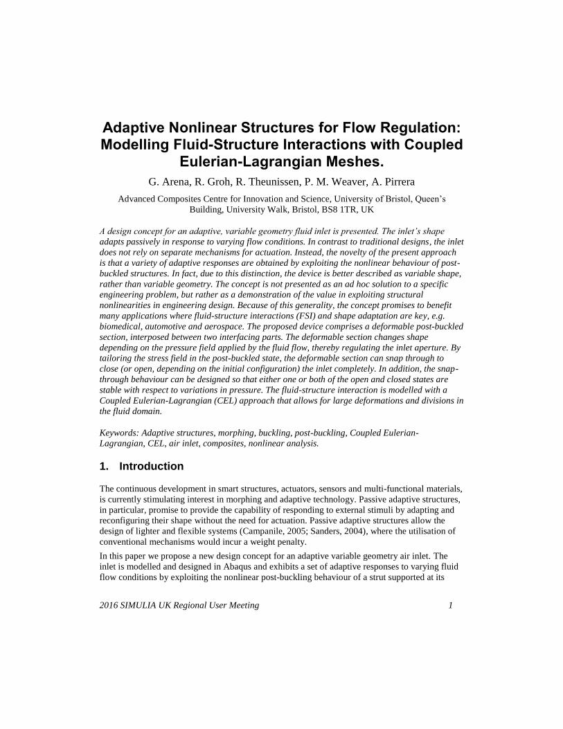
extremities. For the passive adaptation, the device, shown in Figure 1, exploits changes in fluid
pressure caused by the air flowing over the curved geometry.
A post-buckled structure is said to be multi-stable when it can take two or more equilibrium states
for the same set of external loading conditions (Timoshenko, 2009). The most basic example is the
classical Euler beam loaded in compression, which upon reaching a critical load, loses stability on
the initially flat equilibrium path thereby snapping transversally onto one of two possible
sinusoidal shapes.
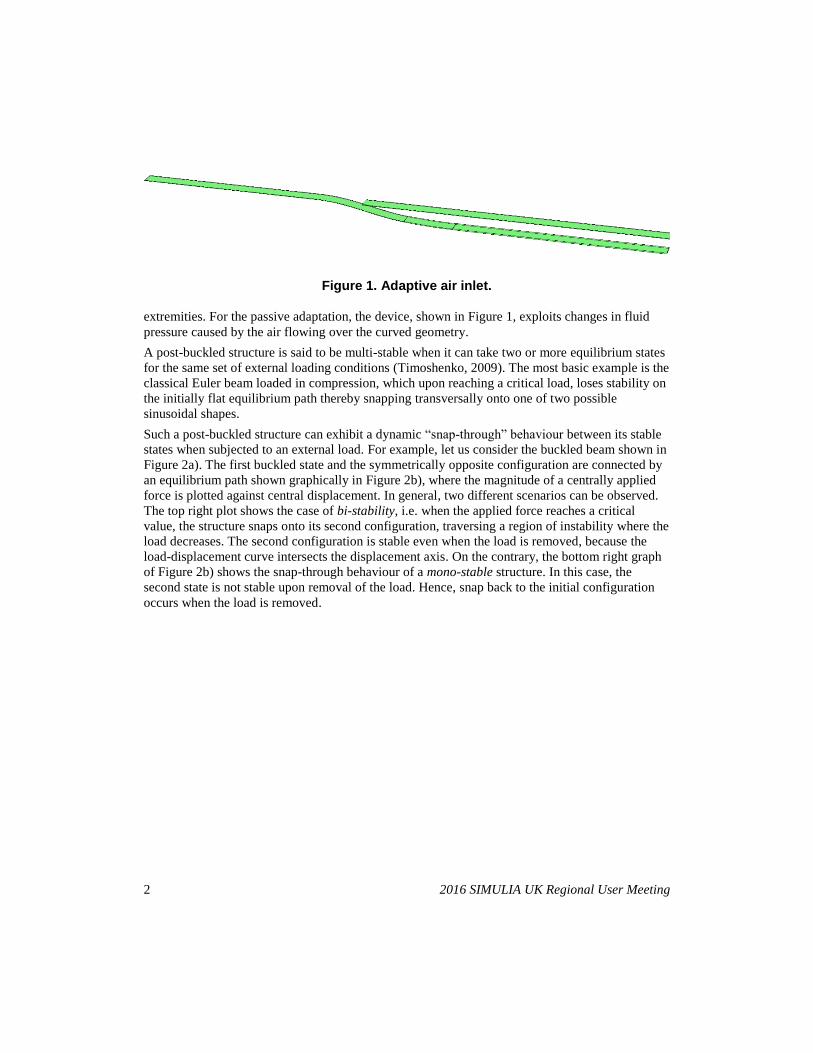
Such a post-buckled structure can exhibit a dynamic “snap-through” behaviour between its stable
states when subjected to an external load. For example, let us consider the buckled beam shown in
Figure 2a). The first buckled state and the symmetrically opposite configuration are connected by
an equilibrium path shown graphically in Figure 2b), where the magnitude of a centrally applied
force is plotted against central displacement. In general, two different scenarios can be observed.
The top right plot shows the case of bi-stability, i.e. when the applied force reaches a critical
value, the structure snaps onto its second configuration, traversing a region of instability where the
load decreases. The second configuration is stable even when the load is removed, because the
load-displacement curve intersects the displacement axis. On the contrary, the bottom right graph
of Figure 2b) shows the snap-through behaviour of a mono-stable structure. In this case, the
second state is not stable upon removal of the load. Hence, snap back to the initial configuration
occurs when the load is removed.
Figure 1. Adaptive air inlet.
2016 SIMULIA UK Regional User Meeting 3
These two concepts are exploited here to design both mono- and bi-stable air inlets, where the
force driving the snap-through is the variation in pressure of the fluid flowing over the surface of
the inlet. Fluid-Structure Interaction (FSI) simulations have been carried out in Abaqus to study
the inlet’s response to varying fluid flow conditions.
The fluid domain discretization is a crucial aspect for FSI simulations with extreme deformations
(Abaqus documentation, 2016; Bavo, 2016; Yu, 2019; Sillem, 2008), with the two main
approaches available in Abaqus being the “ALE (Arbitrary Lagrangian-Eulerian) Abaqus/standard
- explicit co-simulation” and the “Abaqus/CEL (Coupled Eulerian-Lagrangian)”. The advantage of
the ALE method is that more accurate results are obtained at the fluid-structure boundary. On the
other hand, large fluid mesh deformations and distortions can occur. In the CEL analysis (Noh,
1964), the Lagrangian structure can move freely through a stationary fluid mesh. It is important to
highlight that, for flow problems, the CEL method is an implementation of CFD (Computational
Fluid Dynamics) for which results are generally less accurate than for ALE (Abaqus
documentation, 2016).
In this work, we used a CEL approach to simulate the interaction of the morphing inlet with the
airflow. An ALE model was used to validate the results. However, the latter method uses a
traditional CFD solver, which results in more accurate calculations, but suffers from extreme mesh
distortion when the air inlet closes. As a consequence, the ALE simulation could not be used to
analyse the entire operational domain.
Figure 2. Buckled beam configurations before and after the "snap-through" (a). Force vs central displacement of a bi- and mono-stable structure (top and bottom (b),
respectively).
(a) (b)
4 2016 SIMULIA UK Regional User Meeting
2. Fluid-Structure Interaction
Fluid-structure interaction is the study of the effect of a fluid on a deformable structure, and vice
versa. In this kind of problems, the pressure and velocity of the fluid influence, and are influenced
by, the displacements of the structure (Bungartz, 2006).
2.1 Methods: Arbitrary Lagrangian-Eulerian and Coupled Eulerian-Lagrangian
Abaqus/CEL is a recently released extension of Abaqus/Explicit. With this method, the interaction
between fluid and structure is solved by means of contact constraints. On the other hand, the ALE
formulation takes advantage of the coupling of Abaqus/CFD and Abaqus/Standard solvers
(Abaqus documentation, 2016), and is therefore also known as a “co-simulation”.
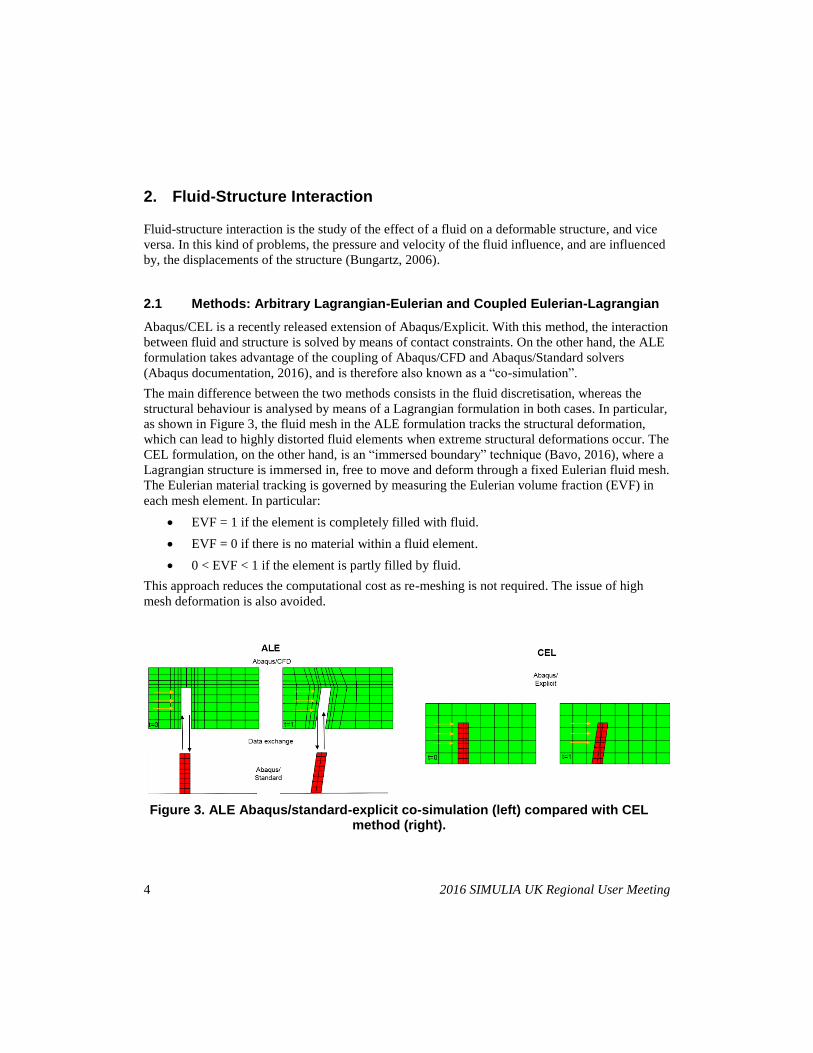
The main difference between the two methods consists in the fluid discretisation, whereas the
structural behaviour is analysed by means of a Lagrangian formulation in both cases. In particular,
as shown in Figure 3, the fluid mesh in the ALE formulation tracks the structural deformation,
which can lead to highly distorted fluid elements when extreme structural deformations occur. The
CEL formulation, on the other hand, is an “immersed boundary” technique (Bavo, 2016), where a
Lagrangian structure is immersed in, free to move and deform through a fixed Eulerian fluid mesh.
The Eulerian material tracking is governed by measuring the Eulerian volume fraction (EVF) in
each mesh element. In particular:
EVF = 1 if the element is completely filled with fluid.
EVF = 0 if there is no material within a fluid element.
0 < EVF < 1 if the element is partly filled by fluid.
This approach reduces the computational cost as re-meshing is not required. The issue of high
mesh deformation is also avoided.
Figure 3. ALE Abaqus/standard-explicit co-simulation (left) compared with CEL method (right).

2016 SIMULIA UK Regional User Meeting 5
The second major difference between the two approaches is the FSI interface tracking method.
The CEL uses the so-called volume of fluid (VOF) method (Hirt, 1981), which applies a contact
between fluid and structure when, at the specific interface node, the EVF arithmetic mean of the
surrounding elements is higher the 0.5. If the mean EVF < 0.5, contact is not imposed. The
disadvantage of this approach is that it can lead to “leakage” and inauthentic acceleration of the
fluid (Sillem, 2008). The ALE method, on the other hand, applies kinematic and dynamic
constraints at the fluid-structure boundaries. These constraints enforce equilibrium of the surface
tractions
𝝈𝒇 ∙ 𝒏 = 𝝈𝒔 ∙ 𝒏 , (1)
where 𝝈𝒇 is the traction vector in the fluid, 𝝈𝒔 is the traction vector in the solid, and 𝒏 is the vector
normal to the boundary. Furthermore, the “no slip” condition
𝒖𝒇 =𝝏𝒅𝒔
𝝏𝒕 (2)
must hold, where u and d are velocity and displacement vectors, respectively. In this way, the
structural geometry within the fluid mesh is defined exactly.
The ALE method simulates the fluid dynamics by means of the Abaqus/CFD solver, which solves
the incompressible form of the Navier-Stokes equations. Conversely, the CEL method uses an
equation of state (EOS), relating pressure (p), density (ρ) and specific energy (Em), in combination
with the compressible form of the Navier-Stokes equations (Abaqus documentation, 2016).
For the problem considered here, the CEL approach was chosen for the following reasons:
The ALE co-simulation requires a perfect match between the structural geometry in
Abaqus/Standard and the structural profile within the fluid domain in Abaqus/CFD. For
this reason, it is not possible to start from a previously defined orphan mesh of the
buckled air inlet. The pre-compression step, required to induce multi-stability, must be
performed within an ALE “co-simulation”. The CEL method, however, allows a buckled
orphan mesh from a previous analysis to be imported.
The ALE co-simulation is computationally very expensive due to the extreme
deformation of the structure and the re-meshing of the fluid volume.
Contact between different structural parts is not possible in the fluid mesh of the ALE
model, as this would cause fluid elements to collapse. The adaptive air inlet studied here
requires contact between the buckled multi-stable part and the inlet cover.
Abaqus/CFD can only solve the incompressible form of the Navier-Stokes equations. In
most CFD studies, air can be considered to be an incompressible fluid. In the problem
considered here, the contact between the cover and the adaptive structure compresses and
displaces the air and hence, for computational stability, accounting for compressibility is
advised.
Even though the CEL method was chosen as more appropriate for this study, the fluid flow
analysis carried out with this method is generally considered to be a less accurate implementation
of CFD simulations (Abaqus documentation, 2016). For this reason, an ALE model was also run
up to point of unfeasible mesh distortion to provide a benchmark and validation for the results and
phenomena shown.
6 2016 SIMULIA UK Regional User Meeting
3. ABAQUS model
To study the actuation of the air inlet by changes in fluid flow and pressure over the surfaces of
the structure, several different types of analyses were conducted:
An Abaqus/Standard analysis for the post-buckling behaviour of both bi-stable and a
mono-stable structures.
An ALE Abaqus/Standard and Abaqus/CFD co-simulation on a mono-stable structure in
order to demonstrate the possibility of actuation via fluid flow.
An ALE Abaqus/Standard and Abaqus/CFD co-simulation on a mono-stable air inlet. As
contact between the air inlet and the cover is not possible in this type of analysis due to
excessive mesh distortion, the model was not run to completion. Nevertheless, the results
obtained prior to mesh collapse can be used to validate the CEL fluid flow results.
A CEL model to study the adaptive response of bi- and mono-stable air inlets to fluid
flow.
3.1 Multistable structures
Finite element models of the bi-stable and mono-stable adaptive inlet are constructed. The material
chosen for both the inlets is a UD (uni-directional) glass fibre epoxy resin composite, Glass/913,
with material properties as shown in Table 1. The bi-stable structure is composed of eight layers
with a constant total thickness of 1.04 mm, a length of 150 mm and width of 11.2 mm. A vertical
displacement of 15 mm and 1.5 mm of pre-compression are applied to one of the ends of the inlet.
Table 1. Glass/913 layer properties.
E1 E2 G12 ν12 Thickness
43.7 GPa 7.5 GPa 4.3 GPa 0.3 0.130 mm
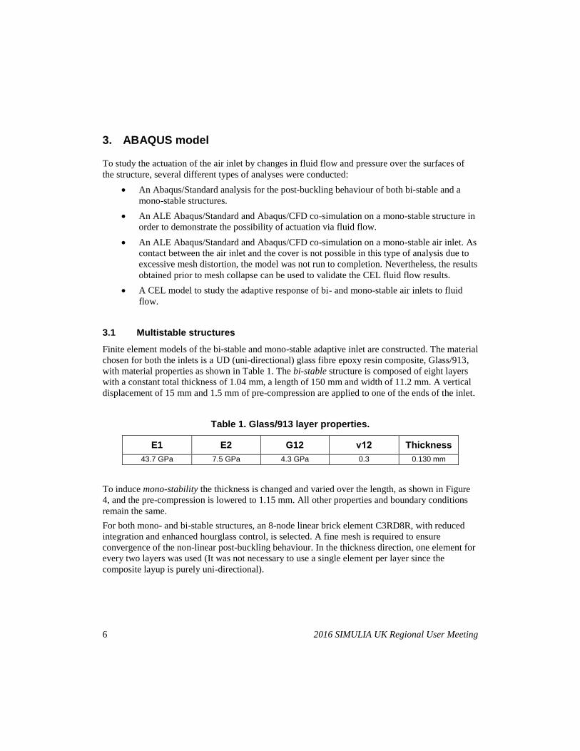
To induce mono-stability the thickness is changed and varied over the length, as shown in Figure
4, and the pre-compression is lowered to 1.15 mm. All other properties and boundary conditions
remain the same.
For both mono- and bi-stable structures, an 8-node linear brick element C3RD8R, with reduced
integration and enhanced hourglass control, is selected. A fine mesh is required to ensure
convergence of the non-linear post-buckling behaviour. In the thickness direction, one element for
every two layers was used (It was not necessary to use a single element per layer since the
composite layup is purely uni-directional).
2016 SIMULIA UK Regional User Meeting 7
As a preliminary study, the non-linear snap-through behaviour in the absence of air was evaluated
with an arc-length Riks algorithm (Riks, 1979). In the ALE co-simulation, the structural results
were obtained with a dynamic implicit solver, whereas in the CEL analysis a dynamic explicit
integration solver was used.
An isotropic elastic material with a Young’s modulus of 70 GPa was used for the inlet cover. In
the ALE co-simulation, a thinner structure was used to minimise element distortion.
3.2 Fluid domain
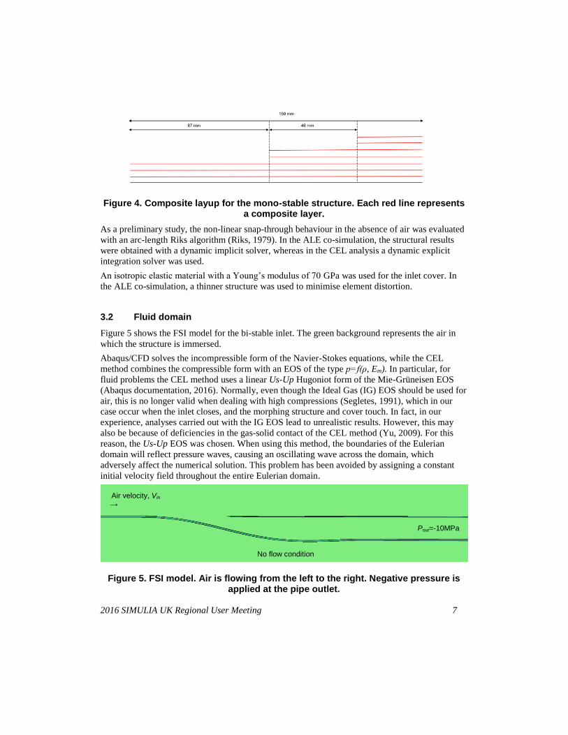
Figure 5 shows the FSI model for the bi-stable inlet. The green background represents the air in
which the structure is immersed.
Abaqus/CFD solves the incompressible form of the Navier-Stokes equations, while the CEL
method combines the compressible form with an EOS of the type p=f(ρ, Em). In particular, for
fluid problems the CEL method uses a linear Us-Up Hugoniot form of the Mie-Grüneisen EOS
(Abaqus documentation, 2016). Normally, even though the Ideal Gas (IG) EOS should be used for
air, this is no longer valid when dealing with high compressions (Segletes, 1991), which in our
case occur when the inlet closes, and the morphing structure and cover touch. In fact, in our
experience, analyses carried out with the IG EOS lead to unrealistic results. However, this may
also be because of deficiencies in the gas-solid contact of the CEL method (Yu, 2009). For this
reason, the Us-Up EOS was chosen. When using this method, the boundaries of the Eulerian
domain will reflect pressure waves, causing an oscillating wave across the domain, which
adversely affect the numerical solution. This problem has been avoided by assigning a constant
initial velocity field throughout the entire Eulerian domain.
Figure 4. Composite layup for the mono-stable structure. Each red line represents a composite layer.
Air velocity, Vin →
Pout=-10MPa
No flow condition
Figure 5. FSI model. Air is flowing from the left to the right. Negative pressure is applied at the pipe outlet.
8 2016 SIMULIA UK Regional User Meeting
The air flowing over the structure was modelled as Newtonian fluid, with density ρ = 1.205 kg/m3
and viscosity μ = 1.915·10-5 Pa·s – the standard properties at 25 °C and atmospheric pressure
(ISO, 1972). CEL simulations, require a compressibility factor as an input. This is derived from
the speed of sound in air, which is normally equal to c = 346 m/s at 25 °C. Nevertheless, here, c is
increased to 1000 m/s to enforce incompressibility.
As the Us-Up EOS was originally derived for compressibility in solids and not air, the results
obtained from the CEL simulation have been validated with ALE co-simulation results. In the
ALE validation study the model is run until the analysis aborts due to excessive mesh distortions
caused by the closing inlet.
For both models a static relative pressure P = 0 was assigned beneath the air inlet where no fluid is
assumed to flow. At the outlet of the air duct, a negative pressure Pout= -10 MPa was chosen in
order to avoid flow reversal. The inlet velocity was increased from 40 to 150 m/s in the ALE co-
simulation, to detect the critical velocity that initiates the snap-through of the structures. As the
minimum critical velocity for both the bi- and mono-stable inlets was found to be around 60 m/s,
this velocity was applied as inlet velocity boundary condition for the CEL method.
Only one element was used through the width of the domain. The size of the fluid domain was
chosen to be large enough (0.5 x 0.4 m) to minimise any boundary effects. In order to achieve
better convergence properties, a more refined mesh was used around the air inlet where extreme
structural deformation occurs. In the CEL model, the entire Eulerian domain was filled with air, so
that the EVF is equal to 1 everywhere.
3.3 Fluid-Structure Interaction
In the ALE co-simulation model, the fluid-structure co-simulation boundary imposes the
kinematic and dynamic constrains (Equations (1) and (2)𝝈𝒇 ∙ 𝒏 = 𝝈𝒔 ∙ 𝒏 , (1) and a
“no-slip” condition. In the CEL model, a general contact interaction is set to the no-slip contact,
and no flow separation is allowed.
Figure 5 shows the CEL model. The Lagrangian structure is immersed in the Eulerian fluid
domain which flows from left to right. The ALE FSI model is identical to the CEL model apart
from the fact that the structure starts from a flat configuration, and is then buckled into the
required configuration in a preliminary load step. The inlet velocity is then ramped-up when the
structure has reached the first stable post-buckling position corresponding to an open duct, and can
then be snapped into the closed configuration.
(a) (b)
2016 SIMULIA UK Regional User Meeting 9
Figure 6. a) Snap-through of the bi-stable inlet. b) snap-though of the mono-stable inlet.
4. Results
4.1 Structural analysis
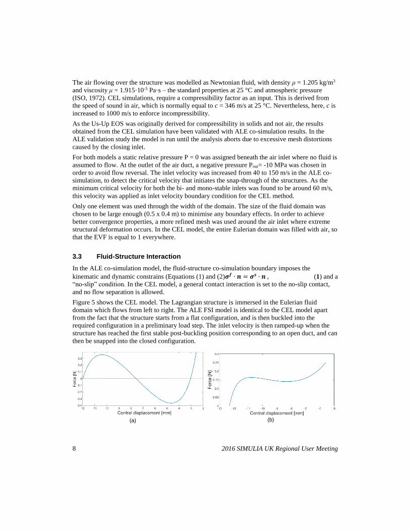
Figure 6 below shows a force-displacement curve for a point located at the mid-span of the device,
and the typical snap-through behaviour discussed with Figure 2b). The curve of the left hand plot
is for the mono-stable configuration; the other is for the bi-stable structure, which were both
introduced in Section 3.1. Both structures show a snap-through behaviour, but with different
loading-unloading paths. The bi-stable structure has a stable second configuration, whereas the
mono-stable snaps-back upon removal of the load.
4.2 ALE Abaqus/CFD and Abaqus/Standard co-simulation
The first FSI simulation focused on the adaptive response of the mono-stable structure to high-
speed airflow. In this initial study the presence of the cover was ignored in order to prove the
feasibility of designing a morphing air inlet passively driven by intrinsic non-linear behaviour.
The results show the validity of using airflow as an actuator for this type of multi-stable structure
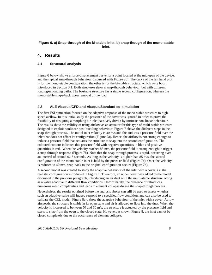
designed to exploit nonlinear post-buckling behaviour. Figure 7 shows the different steps in the
snap-through process. The initial inlet velocity is 40 m/s and this induces a pressure field over the
inlet that does not affect its configuration (Figure 7a). Hence, the airflow is not strong enough to
induce a pressure field that actuates the structure to snap into the second configuration. The
coloured contour indicates this pressure field with negative quantities in blue and positive
quantities in red. When the velocity reaches 85 m/s, the pressure field is strong enough to trigger
a snap-through response (Figure 7b). Note that the snap-through process is rapid, occurring over
an interval of around 0.15 seconds. As long as the velocity is higher than 85 m/s, the second
configuration of the mono-stable inlet is held by the pressure field (Figure 7c). Once the velocity
is reduced to 40 m/s, snap-back to the original configuration occurs (Figure 7d).
A second model was created to study the adaptive behaviour of the inlet with a cover, i.e. the
realistic configuration introduced in Figure 1. Therefore, an upper cover was added to the model
discussed in the previous paragraph, introducing an air duct with the multi-stable structure acting
as a valve adaptive to different flow conditions. Unfortunately, the presence of introduces
numerous mesh complexities and leads to element collapse during the snap-through process.
Nevertheless, the results obtained before the analysis aborts can still be used to assess whether
such an adaptive valve will indeed respond to a specified flow condition, and can also be used to
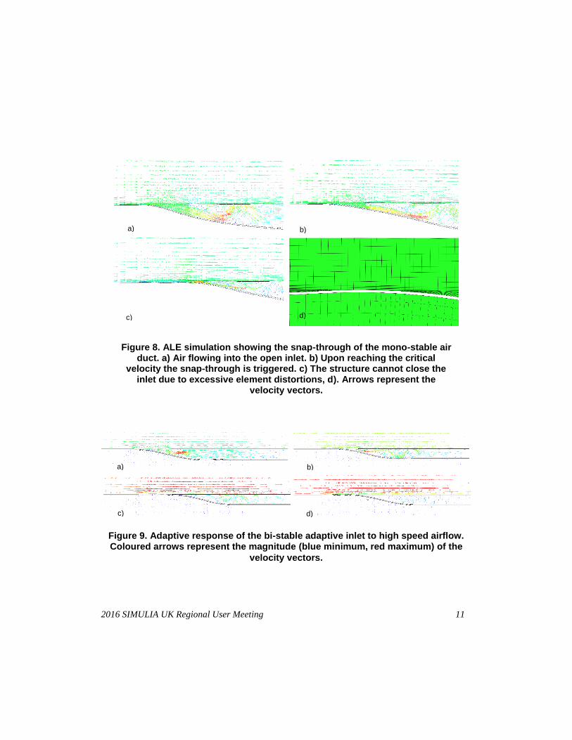
validate the CEL model. Figure 8a-c show the adaptive behaviour of the inlet with a cover. At low
airspeeds, the structure is stable in its open state and air is allowed to flow into the duct. When the
velocity is increased to between 50 and 60 m/s, the structure is actuated by the pressure field and
starts to snap from the open to the closed state. However, as shown Figure 8, the inlet cannot be
closed completely due to the occurrence of element collapse.
10 2016 SIMULIA UK Regional User Meeting
4.3 CEL simulation
A complete study of the snap-through process was carried out by means of the CEL method, as
this does not lead to excessive mesh distortions.
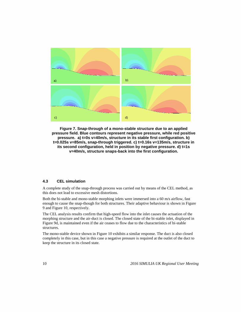
Both the bi-stable and mono-stable morphing inlets were immersed into a 60 m/s airflow, fast
enough to cause the snap-though for both structures. Their adaptive behaviour is shown in Figure
9 and Figure 10, respectively.
The CEL analysis results confirm that high-speed flow into the inlet causes the actuation of the
morphing structure and the air-duct is closed. The closed state of the bi-stable inlet, displayed in
Figure 9d, is maintained even if the air ceases to flow due to the characteristics of bi-stable
structures.
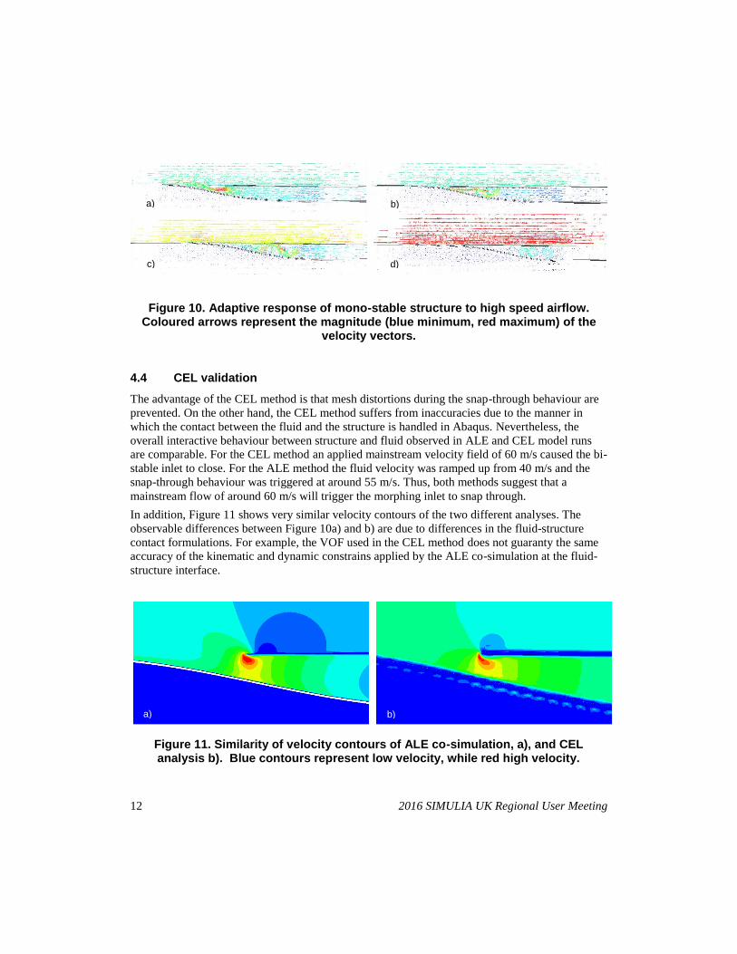
The mono-stable device shown in Figure 10 exhibits a similar response. The duct is also closed
completely in this case, but in this case a negative pressure is required at the outlet of the duct to
keep the structure in its closed state.
a) b)
d) c)
Figure 7. Snap-through of a mono-stable structure due to an applied pressure field. Blue contours represent negative pressure, while red positive
pressure. a) t=0s v=40m/s, structure in its stable first configuration. b) t=0.025s v=85m/s, snap-through triggered. c) t=0.16s v=135m/s, structure in
its second configuration, held in position by negative pressure. d) t=1s v=40m/s, structure snaps-back into the first configuration.
2016 SIMULIA UK Regional User Meeting 11
Figure 9. Adaptive response of the bi-stable adaptive inlet to high speed airflow. Coloured arrows represent the magnitude (blue minimum, red maximum) of the
velocity vectors.
b)
c) d)
a)
Figure 8. ALE simulation showing the snap-through of the mono-stable air duct. a) Air flowing into the open inlet. b) Upon reaching the critical
velocity the snap-through is triggered. c) The structure cannot close the inlet due to excessive element distortions, d). Arrows represent the
velocity vectors.
a) b)
d) c)
a) b)
d) c)
12 2016 SIMULIA UK Regional User Meeting
Figure 10. Adaptive response of mono-stable structure to high speed airflow. Coloured arrows represent the magnitude (blue minimum, red maximum) of the
velocity vectors.
4.4 CEL validation
The advantage of the CEL method is that mesh distortions during the snap-through behaviour are
prevented. On the other hand, the CEL method suffers from inaccuracies due to the manner in
which the contact between the fluid and the structure is handled in Abaqus. Nevertheless, the
overall interactive behaviour between structure and fluid observed in ALE and CEL model runs
are comparable. For the CEL method an applied mainstream velocity field of 60 m/s caused the bi-
stable inlet to close. For the ALE method the fluid velocity was ramped up from 40 m/s and the
snap-through behaviour was triggered at around 55 m/s. Thus, both methods suggest that a
mainstream flow of around 60 m/s will trigger the morphing inlet to snap through.
In addition, Figure 11 shows very similar velocity contours of the two different analyses. The
observable differences between Figure 10a) and b) are due to differences in the fluid-structure
contact formulations. For example, the VOF used in the CEL method does not guaranty the same
accuracy of the kinematic and dynamic constrains applied by the ALE co-simulation at the fluid-
structure interface.
a) b)
Figure 11. Similarity of velocity contours of ALE co-simulation, a), and CEL analysis b). Blue contours represent low velocity, while red high velocity.
a) b)
d) c)
2016 SIMULIA UK Regional User Meeting 13
5. Discussion and conclusions
Two different fluid-structure interaction models conducted in Abaqus suggest the possibility of
designing adaptive, variable geometry fluid inlets. The actuation of the inlet is not governed by
ancillary devices but passively driven by an interplay between airflow over the inlet’s external
surface and intrinsic geometric non-linearity of inlet structure. In particular, bi-stable and mono-
stable air ducts were designed and their responses to high-speed airflow investigated. Both fluid-
structure interaction models showed that pressure fields, caused by the high-speed airflow,
triggered a snap-through of the inlet from an open to a closed state.
Such non-linearities are often shunned in engineering design as they are believed to add
unpredictable behavioural complexity and difficulties in analysis. However, the present work
shows that, when properly designed, such non-linearities can be very effectively exploited for
multi-functional and hence more lightweight design. In this regard the results presented are not a
solution for a specific application, but a validation of the CEL approach for extreme deformation
FSI problem, and the unique characteristics of multi-stable structures.
6. References
1. Abaqus Inc., Abaqus Analysis User's Manual, Version 6.16.
2. Bavo, A.M., G. Rocatello, F. Iannaccone, J, Degroote, J Vierendeels and P. Segers, "Fluid-
Structure Interaction Simulation of Prosthetic Aortic Valves : Comparison between Immersed
Boundary and Arbitrary Lagrangian-Eulerian Techniques for the Mesh Representation," Plos
One, Apr. 2016.
3. Bungartz, H.-J. and M. Schäfer, "Fluid-Structure Interaction. Modelling, Simulation,
Optimization," Springer, 2006.
4. Campanile, L.F. and S. Anders, "Aerodynamic and Aeroelastic Amplification in Adaptive
Belt-rib Airfoils," Aerospace Science and Technology, vol. 9 (2005): 55–63.
5. Hirt, C.W. and B.D. Nichols, "Volume of Fluid (VOF) Method for the Dynamics of Free
Boundaries," Journal of Computational Physics, vol. 39, no. 1 (1981): 201–225.
6. Noh, W.F., "CEL: A Time-Dependent, Two Space Dimensional, Coupled Eulerian–Lagrange
Code," Methods in Computational Physics, vol. 3 (1964): 117–179.
7. Riks, E., "An Incremental Approach to the Solution of Snapping and Buckling Problems,"
International Journal of Solids and Structures, vol. 15 (1979): 529–551.
8. Sanders, B., D. Cowan and L. Scherer, "Aerodynamic Performance of the Smart Wing
Control Effectors," Journal of Intelligent Materials Systems and Structures, vol 15, no. 4
(2004): 293–303.
9. Segletes, S.B., "An Analysis on the Stability of the Mie-Gruneisen Equation of State for
Describing the Behavior of Shock Loaded Materials," U.S. Army Laboratory Command,
Report BRL-TR-3214, March 1991.
10. Sillem, A., "Feasibility Study of a Tire Hydroplaning Simulation in a Finite Element Code
Using a Coupled Eulerian-Lagrangian Method," Master of Science Thesis, TU Delft, 2008.
14 2016 SIMULIA UK Regional User Meeting
11. International Organization for Standardization, "ISO Standard Atmosphere", 1972.
12. Timoshenko, S.P. and J.M. Gere, "Theory of elastic stability," Courier Corporation, 4 May
2012.
13. Yu, H., Y. Tang, J. Gordon and D, Jeong, "Finite Element Analysis of Fluid-Structure
Interaction in Pressurized Tank Cars Subjected To Dynamic Impact Loading," Proceedings
SIMULIA Customer Conference, 2009.
7. Acknowledgements
This work was funded by the Engineering and Physical Sciences Research Council under grant
number EP/M013170/1. The authors would like to acknowledge Clint Davies-Taylor and the
SIMULIA UK technical team for their support.