Area Separation Walls - 2007 - Construction
12
Area Separation Walls Mold and Moisture Resistant PAPERLESS SOLUTIONS
Transcript of Area Separation Walls - 2007 - Construction

Area Separation Walls
Moldand Moisture
Resistant
PAPERLESSSOLUTIONS

Table of Contents
Overview . . . . . . . . . . . . . .2
Installation Instructions . .3
Special Conditions . . . . . .4
Assemblies . . . . . . . . . . . .5
Details . . . . . . . . . . . . . . .6
ArchitecturalSpecifications . . . . . . . . .10
Overview
2 • For latest information and updates: Technical Service Hotline 1.800.225.6119 or www.gpgypsum.com
When tested, as manufactured,in accordance with ASTMD 3273, DensGlass UltraTM
Shaftliner panels scored a 10,the highest level of perform-ance for mold resistanceunder the ASTM D 3273 testmethod.
The score of 10, in the ASTMD 3273 test, indicates no moldgrowth in a 4-week controlledlaboratory test. The moldresistance of any buildingproduct when used in actualjob site conditions, may notproduce the same results aswere achieved in the con-trolled, laboratory setting.No material can be consideredmold proof. When properlyused with good design, handlingand construction practices,products with DensTM Technologyprovide increased mold resist-ance compared to standardpaper faced wallboard.
The G-P Gypsum Area Separation Wall assembly is designed for use in multi-family, multi-story townhouseswith a total height up to 50 feet (page 11, Section 3.3). Because it is constructed using gypsum board, theassembly is easy to erect and secure, meets all building code requirements, and provides economical fireprotection and sound control.The Area Separation Wall is constructed once the framing for one townhouse unit is complete and prior tothe construction of the adjacent unit. The assembly is constructed at the foundation and continues either tothe underside of the protected roof sheathing or through the roof to form a parapet. The assembly is linkedto the adjacent framing with aluminum breakaway clips that allow for collapse of the fire-exposed unitwithout collapse of the solid Area Separation Wall.Because the assembly will be exposed to the elements during construction, G-P Gypsum offers increasedprotection to the owner, builder and architect with a paperless, moisture and mold resistant shaftliner panel– DensGlass UltraTM Shaftliner.
Components
The G-P Gypsum Area Separation Wall is constructed using 1-inch thick, 24-inch wide paperless DensGlassUltra Shaftliner panels, 25 gauge steel H-studs, 25 gauge steel C-track and .062" aluminum breakaway clips.DensGlass Ultra Shaftliner panels consist of a moisture resistant core surfaced with coated fiberglass matfacings. DensGlass Ultra Shaftliner panels are offered with a 6-month in-place exposure limited warrantyand a 5-year limited warranty against delamination, deterioration and decay.Fire Testing and Building Code Compliance
The G-P Gypsum Area Separation Wall has been fire tested to ASTM E 119 and CAN/ULC S-101. TheG-P Gypsum 2-hour fire-rated Area Separation Wall assembly, constructed using DensGlassUltra Shaftlinerpanels, is listed by Underwriters Laboratory (UL), Underwriters Laboratories of Canada (ULC) and WarnockHersey International (WHI/ITS) and meets the requirements of the 2006 International Building Code (IBC)Section 503.2 “Party Walls”, and Section 705, “Fire Walls”. The G-P Gypsum Area Separation Wall assemblyis listed in the UL Fire Resistance Directory under UL Design U 373, the ULC Fire Resistance Directory ULCDesign No. W 312 and the WHI Fire Resistance Directory under WHI 120-04. For copies of these listings,please contact G-P Gypsum Technical Services at 1-800-225-6119.
2x4 Wood Framing
1" DensGlass Ultra Shaftliner Panel
Insulation
Min. 3/4" air space between2" Area Separation Wall and
Wood Framing
2" H-Studs 24" o.c.
Back-to-back C-Tracks
1/2" Gypsum Wallboard or1/2" DensArmor PlusTM
Gypsum Panel
Aluminum Breakaway Clip
Fire Blocking per Code
Area Separation Walls

Installation Instructions
The G-P Gypsum Area Separation Wall is constructed once the framing for one townhouse unit is completeand prior to the construction of the adjacent unit. The solid 2" Area Separation Wall is constructed a mini-mum 3/4" away from the adjacent framing, which is typically constructed from wood. In many cases the areaseparation wall is positioned 1" away from the wall framing to accommodate the 1" DensGlass UltraTM
Shaftliner panels used as fireblocking between the floor levels. The UL Design U373 Area Separation Wallassembly was evaluated at a height up to 44' and the WHI/ITA 120-04 Area Separation Wall assembly wasevaluated at a height up to 50'.
Erecting the 2" Area Separation Wall
1. Position 2" C-Track a minimum 3/4" from the framed wall of the adjacent unit. Fasten C-Track tofoundation with fasteners spaced a maximum of 24" o.c. When specified, apply a minimum 1/4" bead ofacoustical sealant under the C-Track to maximize acoustical privacy. Run the C-Track to the end of thefoundation. In the case of offset units, run the C-Track to the end of the offset unit.
2. Install H-Studs and 1" DensGlass Ultra Shaftliner panels to a maximum height of 2' above the first floorline. Install two 1" shaftliner panels vertically with either side facing out into the C-Track at one end ofthe wall. Install the H-Stud over the double beveled edges of the shaftliner panels and continue alternatelyuntil the wall has reached the opposite end of the foundation. Terminate the wall using a C-Track. Thevertical C-Tracks at each end of the wall should be attached in the corners to the horizontal sections ofC-Track using a minimum of one 3/8" minimum length pan head screw.* Note: some authorities may require labeling to be visible.
3. Cap the first section of the Area Separation Wall with a C-Track and attach to the vertical C-Track in thecorners using a minimum of one 3/8" minimum length pan head screw.
4. Breakaway clips span the minimum 3/4" air space and provide a fusible link between the H-Studs andthe adjacent wall framing. Attach the breakaway clips to the flange of the H-Stud using a minimum ofone 3/8" minimum length pan head screw and to the adjacent wood framing using a minimum of one1" minimum length drywall screw.When the UL Design U373 Area Separation Wall assembly is specified, the breakaway clips should belocated vertically at each floor level (10'0" o.c.) and horizontally on every H-Stud (24" o.c.). When the totalheight of the Area Separation Wall exceeds 20'0", breakaway clips shall be installed every 5'0" for thelower 20'0" and every 10'0" for the upper 24'0" of the wall assembly. Breakaway clips are installed onboth sides of the Area Separation Wall.When the WHI/ITS Design WHI 120-04 Area Separation Wall assembly is specified, the breakaway clipsshould be located vertically at each floor level (10'0" o.c.) and horizontally on every other H-stud (48" o.c.).When the total height of the Area Separation Wall exceeds 20'0", breakaway clips shall be installedvertically every 8'0" maximum for the lower 20'0" and every 10'0" maximum for the upper 30'0" of thewall assembly.
5. Fireblocking is installed on both sides of the Area Separation Wall at each floor level as defined inSection 717.2.1 of the 2003 IBC. (See details section). For approved fire-blocking materials, see SpecialConditions, Item 9.
6. To continue the wall, install a C-Track over the C-Track used to cap the lower section, placed back toback and attached together with a minimum of one 3/8" minimum length pan head screw spaced 24”o.c.(See details section).
7. The support walls located adjacent to, and on each side of the solid 2" Area Separation Wall, protect andmaintain the required 3/4" air space. These support walls offer increased acoustical privacy and providenecessary aesthetics. They can be designed as load bearing. These walls can readily accommodate codecompliant electrical and plumbing systems. These systems should not impede the required 3/4" air space.Apply acoustical sealant around penetrations for maximum acoustical privacy.
8. If a parapet is not specified, one layer of 5/8" FireguardTM Type X gypsum board, 5/8" DensArmor PlusTM
Fireguard Type X interior panels or 5/8" DensGlass Gold® Fireguard Type X exterior sheathing should beinstalled 4' on both sides of the Area Separation Wall. (4' is required per building code). See SpecialConditions, #11 for two code-compliant methods for installing a gypsum board roof underlayment.
9. Once the 2" Area Separation Wall is erected, construction of the adjacent interior wall framing can begin.Breakaway clip and fire-blocking installation is identical for both sides of the 2" Area Separation Wall.
3 • For latest information and updates: Technical Service Hotline 1.800.225.6119 or www.gpgypsum.com
Aluminum Angle Clip
C-Track, Cap, Edgeor End Closure
H-Stud, 25-Gauge
2"
2-1/4"
2-1/2"
Area Separation Walls
4 • For latest information and updates: Technical Service Hotline 1.800.225.6119 or www.gpgypsum.com
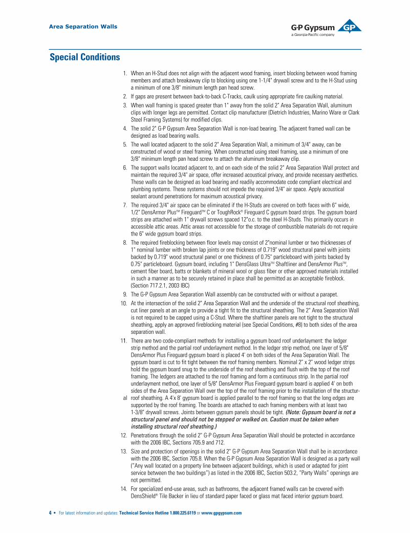
Special Conditions
1. When an H-Stud does not align with the adjacent wood framing, insert blocking between wood framingmembers and attach breakaway clip to blocking using one 1-1/4" drywall screw and to the H-Stud usinga minimum of one 3/8" minimum length pan head screw.
2. If gaps are present between back-to-back C-Tracks, caulk using appropriate fire caulking material.3. When wall framing is spaced greater than 1" away from the solid 2" Area Separation Wall, aluminum
clips with longer legs are permitted. Contact clip manufacturer (Dietrich Industries, Marino Ware or ClarkSteel Framing Systems) for modified clips.
4. The solid 2" G-P Gypsum Area Separation Wall is non-load bearing. The adjacent framed wall can bedesigned as load bearing walls.
5. The wall located adjacent to the solid 2" Area Separation Wall, a minimum of 3/4" away, can beconstructed of wood or steel framing. When constructed using steel framing, use a minimum of one3/8" minimum length pan head screw to attach the aluminum breakaway clip.
6. The support walls located adjacent to, and on each side of the solid 2" Area Separation Wall protect andmaintain the required 3/4" air space, offer increased acoustical privacy, and provide necessary aesthetics.These walls can be designed as load bearing and readily accommodate code compliant electrical andplumbing systems. These systems should not impede the required 3/4" air space. Apply acousticalsealant around penetrations for maximum acoustical privacy.
7. The required 3/4" air space can be eliminated if the H-Studs are covered on both faces with 6" wide,1/2" DensArmor PlusTM FireguardTM C or ToughRock® Fireguard C gypsum board strips. The gypsum boardstrips are attached with 1" drywall screws spaced 12"o.c. to the steel H-Studs. This primarily occurs inaccessible attic areas. Attic areas not accessible for the storage of combustible materials do not requirethe 6" wide gypsum board strips.
8. The required fireblocking between floor levels may consist of 2"nominal lumber or two thicknesses of1" nominal lumber with broken lap joints or one thickness of 0.719" wood structural panel with jointsbacked by 0.719" wood structural panel or one thickness of 0.75" particleboard with joints backed by0.75" particleboard. Gypsum board, including 1" DensGlass UltraTM Shaftliner and DensArmor PlusTM,cement fiber board, batts or blankets of mineral wool or glass fiber or other approved materials installedin such a manner as to be securely retained in place shall be permitted as an acceptable fireblock.(Section 717.2.1, 2003 IBC)
9. The G-P Gypsum Area Separation Wall assembly can be constructed with or without a parapet.At the intersection of the solid 2" Area Separation Wall and the underside of the structural roof sheathing,cut liner panels at an angle to provide a tight fit to the structural sheathing. The 2" Area Separation Wallis not required to be capped using a C-Stud. Where the shaftliner panels are not tight to the structuralsheathing, apply an approved fireblocking material (see Special Conditions, #8) to both sides of the areaseparation wall.
1 There are two code-compliant methods for installing a gypsum board roof underlayment: the ledgerstrip method and the partial roof underlayment method. In the ledger strip method, one layer of 5/8"DensArmor Plus Fireguard gypsum board is placed 4' on both sides of the Area Separation Wall. Thegypsum board is cut to fit tight between the roof framing members. Nominal 2" x 2" wood ledger stripshold the gypsum board snug to the underside of the roof sheathing and flush with the top of the roofframing. The ledgers are attached to the roof framing and form a continuous strip. In the partial roofunderlayment method, one layer of 5/8" DensArmor Plus Fireguard gypsum board is applied 4' on bothsides of the Area Separation Wall over the top of the roof framing prior to the installation of the structur-
al roof sheathing. A 4'x 8' gypsum board is applied parallel to the roof framing so that the long edges aresupported by the roof framing. The boards are attached to each framing members with at least two1-3/8" drywall screws. Joints between gypsum panels should be tight. (Note: Gypsum board is not astructural panel and should not be stepped or walked on. Caution must be taken wheninstalling structural roof sheathing.)Penetrations through the solid 2" G-P Gypsum Area Separation Wall should be protected in accordancewith the 2006 IBC, Sections 705.9 and 712.Size and protection of openings in the solid 2" G-P Gypsum Area Separation Wall shall be in accordancewith the 2006 IBC, Section 705.8. When the G-P Gypsum Area Separation Wall is designed as a party wall(“Any wall located on a property line between adjacent buildings, which is used or adapted for jointservice between the two buildings”) as listed in the 2006 IBC, Section 503.2, “Party Walls” openings arenot permitted.For specialized end-use areas, such as bathrooms, the adjacent framed walls can be covered withDensShield® Tile Backer in lieu of standard paper faced or glass mat faced interior gypsum board.
Area Separation Walls
10.
11.
12.
13.
14.

5 • For latest information and updates: Technical Service Hotline 1.800.225.6119 or www.gpgypsum.com
System Assemblies – 2-Hour Ratings
Two layers 1" DensGlass UltraTM Shaftlinerinserted in H-Studs 24" o.c. Min. 3/4" airspace between liner panels and adjacentwood or metal framing.
Construction Detail Assembly Components STC Test Reference
UL DESIGN U373
WHI 495-074338 est.
Two layers 1" DensGlass Ultra Shaftlinerinserted in H-Studs 24" o.c. Min. 3/4" airspace on both sides must be maintainedbetween liner panels and adjacent framing.
Sound Tested with 2" x 4" stud wall with1/2" DensArmor PlusTM gypsum board eachside of assembly and 3-1/2" glass fiber instud space both sides.
UL DESIGN U373ULC DESIGN W312WHI 120-04RAL TL89-383
60
Part. Thickness: 3"
Weight per Sq. Ft.: 9.5
Two layers 1" DensGlass Ultra Shaftlinerinserted in H-Studs 24" o.c. H-Studs coveredusing 6" wide or 1/2" DensArmor PlusFireguardTM C Interior Panel or 1/2"ToughRock® Fireguard C gypsum board.
Breakaway clip facings and height of wall differ between UL Design U373 and WHI 120-04.
Area Separation Walls

Firewall Basics
6 • For latest information and updates: Technical Service Hotline 1.800.225.6119 or www.gpgypsum.com
Area Separation Walls
©2006
, Georg
ia-Pacif
ic Corp
oration

7 • For latest information and updates: Technical Service Hotline 1.800.225.6119 or www.gpgypsum.com
Area Separation Walls
B. Exterior Wall Intersection
D. Wall-to-Slab Detail
A. Roof-Ceiling Detail
C. Floor Intersection Detail
Concrete Slab
2x4 Plate
Space for AcousticalSealant (as required)
C-shapedMetal Track
FiberglassBatt Insulation
1/2" DensArmor Plus™
Paperless Interior Drywall or 1/2" Wallboard
2 Sheets of1" DensGlass Ultra™
Shaftliner(Firewall)
3/4" minimumAir Space
1/2" DensArmor Plus™
Paperless Interior Drywall
(Ceiling)
Floor Joist
Subfloor
Fiberglass Batt Insulation
2 Sheets of1" DensGlass Ultra™
Shaftliner (Firewall)
Double C-ShapedMetal Track ScrewedBack to Back
3/4" minimum Air Space
Space for AcousticalSealant (as required)
Fire Blocking(as required by code)
TopPlate
Breakaway Clip
Siding
DensArmor Plus™
PaperlessInterior Drywall
1/2" DensArmor Plus™
PaperlessInterior Drywall or 1/2" Wallboard
1/2" DensArmor Plus™
PaperlessInterior Drywall or 1/2" Wallboard
Exterior Wall
Fiberglass Batt Insulation
2" H-Stud
3/4" minimum Air Space
3/4" minimum Air Space
Fire Blocking
C-Shaped MetalTrack Set in Sealant
to Create ASmoke-Tight Joint
(as required)
2 Sheets of1" DensGlass Ultra™
Shaftliner(Firewall)
2 Sheets of1" DensGlass Ultra™
Shaftliner(Firewall)
Roofing
Parapet Cap
As required by code
Flashing
Breakaway Clip
FiberglassBatt Insulation

8 • For latest information and updates: Technical Service Hotline 1.800.225.6119 or www.gpgypsum.com
Details
Area Separation Walls
Full Wall
Roof deck per code requirementRoof truss
Intersection at roof
Back-to-back C-tracks
1-1/4" Drywall screw
Intermediate floor
1" DensGlass UltraTM Shaftliner panels
FoundationSealant, as required2" C-track fastener 24" o.c.
Joist
Acoustic sealant (as required)
Sealant
3/8" Pan head screw
2" x 4" Stud framing
Fire blocking as required
Aluminum break away clip
Attic – Adjacent to Trusses*
1" DensGlass Ultra Shaftliner panels
H-stud
6" Wide 1/2" DensArmor PlusTM C or1/2" ToughRock® FireguardTM C gypsumboard batten strips
Wood truss
No minimum air space
*Only applies if solid wall is accessible.If not accessible, the 1/2" Type C strips are not required.

9 • For latest information and updates: Technical Service Hotline 1.800.225.6119 or www.gpgypsum.com
Details
Area Separation Walls
1 Layer of 5/8" DensArmor PlusTMType X gypsum panel (or as requiredby codes)
2” x 2” ledger strips
Caulk (smoke tight joint)Roofing Roof deck
Fire blocking
Breakaway clip
Insulation
3/4" Minimum air space
1" DensGlass UltraTM Shaftliner panels
Typical Roof Junction
1/2" DensArmor Plus or 1/2" ToughRock® gypsum panel
Typical Offset Roof/Wall Detail
1" DensGlass Ultra Shaftliner panels
Roof Deck
Insulation (optional)
Breakaway clip
Roofing Roof deck
External Cladding
1/2" DensArmor Plus or1/2" ToughRock gypsum panel
3/4" Minimum air space Fire blocking
Flooring

Architectural Specifications
1.0 Description of Work
The type of work specified herein includes, but is not limited to, Area Separation Wall systems.
1.1 Quality Assurance
Fire-Resistance Ratings: Provide fire resistance rated assemblies identical to those indicated by reference toUL (Underwriters Laboratories) or WHI (Warnock Hersey International) ITS numbers or in listings of other agenciesacceptable to authorities having jurisdiction. For fire safety information, visit www.gp.com/gypsum/firesafety.
1.2 Qualifications
All area separation wall shaftliner and gypsum board and joint treatment materials shall be manufactured orprovided by G-P Gypsum Corporation. The steel framing components and aluminum breakaway clips shall beprovided by a steel manufacturer authorized by G-P Gypsum Corporation unless otherwise indicated. All materialsshall be installed in accordance with printed installation instructions as required by the testing agency.
System must be constructed to meet any applicable code requirements.
1.3 Submittals
Product Data: Submit G-P Gypsum’s descriptive literature for each area separation wall component indicatingmaterials, dimensions, finishes and other data required to show compliance with the specifications.
1.4 Delivery, Storage and Handling
Deliver materials in original packages, containers or bundles bearing G-P Gypsum’s brand name and identification.Product also may be wrapped in temporary factory-applied plastic packaging (plastic wrap) that must be removedupon receipt. Failure to remove the plastic shipping covers and plastic wrap may result in entrapmentof condensation or moisture, which may cause application problems.
Store materials flat, inside, under cover. Keep materials dry and protect from weather and damage fromconstruction operations and other causes.
Handle area separation wall components to minimize damage to edges, ends or surfaces. Protect metal acces-sories, framing and trim from bending and damage.
1.5 Project Conditions
Environmental Requirements: Comply with the requirements of gypsum board application standards andrecommendations of G-P Gypsum for environmental conditions before, during and after application of DensGlassUltraTM Shaftliner and ToughRock® or DensArmor PlusTM gypsum board.
ToughRock setting compounds should be used for all bedding and topping coats for cold weather or slow dryingconditions. Easy sanding versions available.
2.0 MaterialsA. Metal Framing:
1. Steel H-Studs, minimum 25-gauge, galvanized, and conforming to applicable sections of ASTM C 645.Lengths as required.
2. C-Track, minimum 25-gauge, galvanized, in 10' lengths.
3. Aluminum breakaway clips, 2" x 2-1/2" x 0.063".
B. Gypsum Board:
1. Shaftliner: 1" DensGlass Ultra Shaftliner, Type X conforming to ASTM C 442 and ASTM C 1396. 24" widewith double beveled edges. Lengths as required.
2. Gypsum board: 1/2" ToughRock FireguardTM C or 5/8" ToughRock Fireguard Type X gypsum board;1/2" DensArmor Plus Fireguard C or 5/8" DensArmor Plus Fireguard Type X conforming to relevantsections of ASTM C 1396, ASTM C 36 and ASTM C 1177. (For fire safety information, visitwww.gp.com/gypsum/firesafety.)
C. Fasteners: For 25-gauge framing, Type S screws.
D. Miscellaneous Materials: Acoustical sealant.
Part 1 – General
Part 2 – Products
10 • For latest information and updates: Technical Service Hotline 1.800.225.6119 or www.gpgypsum.com
Area Separation Walls

3.0 General
Follow G-P Gypsum recommendations for installation of metal framing and gypsum board for area separationwalls.
3.1 Installation
Foundation: Position 2" C-Track at floor and attach securely to foundation at ends and 24" o.c. Caulk under runnerat foundation with min. 1/4" bead of acoustical sealant when specified to reduce noise transmission.
First Floor: Install H-Studs and insert DensGlass Ultra Shaftliner panels. Attach two thicknesses of 1" DensGlassUltra Shaftliner panels vertically in C-Track with long edges in H-Stud. Continue installing H-Studs and shaftlineralternately until wall is complete. Attach horizontal C-Track to top of shaftliner panels, fastening flanges ofC-Track at all corners on both sides of shaftliner with minimum of one 3/8" minimum length drill point screws.
Intermediate Floors: Attach C-Track to C-Track cap on wall below, staggering end joints at least 12". FastenC-Tracks together using two 3/8" minimum length screws at ends and 24" o.c. Fasten H-Studs to adjacent framingwith aluminum breakaway clips. Attach breakaway clips to H-stud with a minimum of one 3/8" minimum lengthdrill point screw and to adjacent wood framing with 1-1/4" drywall screw. Install fire blocking between solidwall system and adjacent framing at floor lines, bottom of truss line and any other locations according to coderequirements. When the UL Design U373 Area Separation Wall assembly is specified, the breakaway clips shouldbe located vertically at each floor level (10'0" o.c.) and horizontally on every H-Stud (24" o.c.). When the totalheight of the Area Separation Wall exceeds 20'0", breakaway clips shall be installed every 5'0" maximum for thelower 20'0" and every 10'0" maximum for the upper 24'0" of the wall assembly. Breakaway clips are installed onboth sides of the Area Separation Wall. When the WHI/ITS Design SHI 120-04 Area Separation Wall assembly isspecified, the breakaway clips should be located vertically at each floor level (10'0" o.c.) and horizontally on everyother H-stud (48" o.c.). When the total height of the Area Separation Wall exceeds 20'0", breakaway clips shallbe installed vertically every 8'0" maximum for the lower 20'0" and every 10'0" maximum for the upper 30'0" of thewall assembly.
Roof: Cut DensGlass Ultra Shaftliner panels and H-Studs to follow roof pitch. Fasten H-Studs to framing with analuminum breakaway clip.
Fiberglass Insulation: Friction-fit fiber glass blanket insulation within cavities.
Interior Finish: Apply gypsum board as specified to wood studs with screws or nails in conventional manner.
3.2 Accessories
Joint System: Finish all face layer joints and internal angles of wood stud wall with ToughRock joint treatmentapplied according to manufacturer’s directions. Spot exposed fasteners on face layers and finish corner bead,control joints and trim as required.
Metal Trim: Where partition or ceiling terminates against masonry or other dissimilar material, apply metal trimover drywall edge.
Control Joints: Gap gypsum board behind joint and back with double framing. Attach control joint on bothflanges along entire length of joint.
3.3 Limitations
Unsupported wall height between floors should not exceed 12 feet. May be used in buildings up to four stories.The UL Design U373 Area Separation Wall assembly was evaluated at a height up to 44' and the WHI/ITS 120-04Area Separation Wall assembly was evaluated at a height up to 50'.
Service cutouts or through penetrations shall be installed and protected in accordance with the building code.
Do not install insulation in the system until the building has been properly closed in.
The specifier or user should determine prior to installation that the local building and fire code authority permitsthe installation of gypsum area separation walls and that the insuring group will not penalize the owner.
Provide for deflection of live-loaded floor assemblies by using relief joints or floating trim.
Part 3 – Execution
11 • For latest information and updates: Technical Service Hotline 1.800.225.6119 or www.gpgypsum.com
Area Separation Walls
©2006 G-P Gypsum Corporation. All rights reserved. Printed in the U.S.A. GEO 11/06. GP Lit. Item #531552.
DensArmor Plus™ Paperless Interior DrywallDensArmor Plus is a new generation paperless drywall designed as a replacement for paper-faced drywall for building interiors.DensArmor Plus drywall incorporates glass mats on the surfaces of the drywall panel instead of paper facings found on traditional drywall.The combination of paperless surfaces and a moisture resistant core provides superior moisture- and mold-resistance when compared totraditional paper-faced drywall. G-P Gypsum offers a three-month in-place exposure warranty which means DensArmor Plus can behung before installing doors and windows. DensArmor Plus installs using the same steps as traditional drywall.
DensGlass Gold® Exterior SheathingDensGlass Gold exterior sheathing is a moisture-resistant gypsum panel that can be used for exterior walls, ceilings and soffits. Itspaperless, glass-mat facings and moisture-resistant core resist the effects of surface water exposure while providing resistance to mold.With a long established track record, DensGlass Gold sheathing is so weather resistant that it is backed with a six-month in-placeexposure warranty. DensGlass Gold is the preferred sheathing for use under brick, stone, stucco and EIFS siding materials. DensGlassGold sheathing is so widely used that its bright GOLD™ color is recognized throughout the industry.
DensShield® Tile BackerDensShield tile backer is a patented substrate for floor, wall and ceiling ceramic tile installations. Designed with a built-in moisture barrier,DensShield protects tile installations and the wall cavity from the effects of moisture in damp areas such as bathrooms and kitchens.Incorporating glass-mat facings and a moisture resistant core, DensShield is lighter and easier to install than heavy, hard-to-work-withcement board tile backers. The combination of moisture and mold resistance, along with potential labor savings, makes DensShield thesuperior substrate for ceramic tile in the industry. Georgia-Pacific backs DensShield tile backer with a lifetime limited warranty whenused in residential tile installations. In addition, DensShield offers a 20 year limited warranty for its use in commercial applications.
DensGlass Ultra™ ShaftlinerDensGlass Ultra Shaftliner is the ideal component for gypsum board shaft wall/stairwell and area separation wall systems when a firerating is required. DensGlass Ultra Shaftliner incorporates a moisture and mold resistant, non-combustible gypsum core with paperlessglass-mat facings to resist exposure to the elements during the early stages of the construction cycle. Backed by a six-month in-placeexposure warranty, DensGlass Ultra Shaftliner is the perfect substitute for heavy, expensive masonry construction. It also offers superiormoisture and mold resistance compared to traditional paper-faced shaftliner wallboard products.
DensDeck® Roof BoardVersatile DensDeck roof board is utilized in a wide variety of roofing systems for new and re-roofing applications as cover boards, overlay-ments, underlayments and separator boards. Featuring a combination of fire resistance, strength, moisture resistance and dimensionalstability, DensDeck roof board enhances the overall performance of most roofing assemblies and is widely respected and specified by lead-ing roofing system manufacturers. DensDeck roof board, with its paperless glass-mat facings, has been shown to withstand delamination,deterioration, warping and job site damage far more effectively than paper-faced gypsum board or other conventional roofing products,such as wood fiberboard and perlite.
DensDeck Prime® Roof BoardDensDeck Prime roof board from G-P Gypsum combines the superior features of DensDeck roof board, including fire resistance, strength,moisture resistance and dimensional stability, with an enhanced surface treatment. The coated surface of DensDeck Prime providesan ideal substrate for a wide variety of adhered roofing systems by allowing a uniform spread of adhesives, which results in a strong,consistent bond. DensDeck Prime can be used in cold mastic, torch applied modified bitumen as well as fully-adhered, single-ply systems.
DensDeck DuraGuard® Roof BoardDensDeck DuraGuard roof board from G-P Gypsum combines the superior features of DensDeck roof boards, including fire resistance,strength, moisture resistance and dimensional stability, with a durable, low perm, integrated coating. This coating provides an idealsubstrate for a wide variety of adhered roofing systems, including self-adhered, hot-mopped membranes, and torched asphaltic systems.The coating assures more uniform spreading of adhesives, an excellent coverage rate, and it enhances the bond strength of membranesystem-to-board without the need for field priming with a number of systems.
www.scscertified.comSCS-RRC-01319
90% Recycled Content
Minimum 90% post-industrial recycled
gypsum, on a dry weight basis
SALES INFORMATION AND ORDER PLACEMENTU.S.A. Midwest: 1-800-876-4746 West: 1-800-824-7503
South: 1-800-327-2344 Northeast: 1-800-947-4497
CANADA Canada Toll Free: 1-800-387-6823Quebec Toll Free: 1-800-361-0486
G-P Gypsum Technical Hotline: U.S.A. and Canada: 1-800-225-6119
Some of our products have been certified by ScientificCertification Systems (SCS). SCS is an internationallyrecognized third-party evaluation, testing andcertification organization. Its program spans a widecross-section of the economy, including manufacturingand retailing, consumer products, the energy industry,and the home improvement and construction sectors.For details on specific G-P Gypsum products and plants,please contact our Technical Hotline at 800-225-6119.
TRADEMARKS DENS, DENSARMORPLUS, DENSDECK, DENSDECKDURAGUARD, DENSDECK PRIME,DENSGLASS GOLD, DENSGLASSULTRA, DENSSHIELD, FIREGUARD,TOUGHROCK and the color GOLDare trademarks of Georgia-PacificCorporation or one of its subsidiaries.
UPDATES AND CURRENTINFORMATION The informationin this document may changewithout notice. Visit our website forupdates and current information.
LIMITATION OF REMEDIES ANDDAMAGES Unless otherwisestated in our written limitedwarranty for these products, oursole liability for any product claimshall be limited to reimbursementof the cost of repair or replacementof the affected product, up to amaximum amount of two timesthe original purchase price for theaffected product. We shall not beresponsible under any circum-stances for lost profits, damageto a structure or its contents, or in-direct, incidental, special orconsequential damages. Claimsshall be deemed waived if theyare not submitted to us in writingwithin ten days after discovery.
SAFETY CAUTION: Some productscontain fiberglass. Fibers and dustmay be released from these productsduring normal handling and mayresult in skin, eye and respiratoryirritation. Avoid breathing dust andcontact with the skin and eyes.Follow these standard work practices:Wear a loose-fitting, long-sleevedshirt and long pants, protectivegloves and eye protection (gogglesor safety glasses with side shields).Wear a dust mask when sanding.Additional protection may beneeded when very dusty. Do notuse a power saw. For MaterialSafety Data Sheet or additionalinformation, call 1-800-225-6119or visit our website.