Area Sensors - Micro Detectors€¦ · Basic theory Area Sensor Introduction induttivi....
36
Area Sensors 201601_MD_Product Catalogue
Transcript of Area Sensors - Micro Detectors€¦ · Basic theory Area Sensor Introduction induttivi....

Area Sensors
201601_MD_Product Catalogue

Under 1 m
From 1 to 2 m
From 2 to 4 m
Over 4 m
Nominal sensing distance Sn
539539201601_MD_Product Catalogue

540201601_MD_Product Catalogue

Basic theoryArea Sensor
Introduction induttivi.Optoelectronic scanners are not covered by the provisions of EN 60947-5-2 and the following details only refer to common parameters. The technical terms of the paragraph headings reflect those used in the wording of this legislation, whilst those in italics are synonyms. The specifications listed relate to the nominal perfor-mance envisaged by said legislation and apply to products whose technical specifications do not include a specific figure.
Operating principleType-T Optoelectronic scanners are made up of two elements; an emitter and a receiver. The emitter has an optical unit that consists of an array of photoemitters which emit a series of narrow luminous pulses to the receiver in a consecutive well-defined manner. Luminous radiation is generated by a solid- state source made up of high-performance long-lasting semiconductor elements. This radiation can be from outside the visible band. The receiver has an optical unit which is made up of an array of photoreceivers which correspond geometrically to those of the emitter. The luminous radiation reaching the photoreceivers is converted to an electric signal, amplified and processed in order to drive receiver output elements. As there is synchronous reading of the luminous pulse, a synchronous signal must be transmitted between emitter/receiver. Detection occurs when the path of the beam is interrupted by the presence of an opaque object.
Parallel-ray scanningEvery pulse emitted by a single element of the emitter array must be synchronously read by the corresponding element of the receiver array so that the single pair can be considered in light state. Every single emitter/receiver pair only controls its own axis of conjunction. Scanning determines an area crossed by parallel rays. Using parallel rays enables precise information to be obtained regarding size and position of target object.
Cross-ray scanningEvery pulse emitted by a single element of the emitter array must be synchronously read by the corresponding element of the receiver array, and by a variable num-ber of other receivers positioned on either side of the central one, so that the single pair can be considered in light state (i.e. path of beam completely clear). Every single emitter/ receiver pair controls a range of axes which originate from the emitter and reach an array of receivers. Scanning determines an area crossed by cross rays in a complex manner. The number of lateral receivers involved in reading the single emitter varies according to the range of the particular model. Every emitter must illuminate various receivers and can only do so if the optical-beam angle is sufficient for a certain distance. The number of receivers enabled can also vary during scanning. In extreme cases the two emitters on the edge of the array may only illuminate the internal lateral receivers because the external ones do not exist. Another case in particular is when single emitters must always illuminate all the receivers. This operating mode is simple to manage but requires large beam angles.Operating with cross rays does not enable precise information to be immediately obtained regarding size and position of target object, but merely reveals its pre-sence.
Synchronising scanningIt is the function which allows a single element of the receiver array to be enabled to read only at the moment in which the luminous pulse is sent by the corresponding emitter element. The synchronisation serves to determine a strict relationship between corresponding emitter and receiver so as to reduce the effects of interference from other signals. With type T parallel-ray scanning sensors used for determining size and position of objects, the synchronisation must be realised by connecting a cable between emitter and receiver. With sensors that are only used for detecting the presence of an object, the synchronisation can be sent optically. Usually an emitter is added to the receiver array sends synchronisation message to an additional receiver in the emitter array. Alternatively, timing techniques can be used for autosynchronisation of the receiver, thus eliminating the need for cabling between emitter and receiver. Devices also exist whose arrays of optical elements alternate between emitters and receivers that pass the optical pulses on to each other. This type of solution is another which does not require cable synchronisation and cannot be used for pinpointing position and size of objects.
State of areaTo define the state of the area or the single elements, reference must be made to the light/dark condition of the receivers. The dark condition is determined by the presence of an opaque object that blocks the path of the rays. The light condition is on the other hand determined by the fact that the path between emitter and receiver is clear.
General descriptionThe area sensors are composed of two elements: an emitter and a receiver element. The optical part is composed of an array of synchronized photoelements in order to avoid mutual interference. The main characteristics are:
• istance between emitter and receiver (D): it indicates the operating distance between the emitter and the receiver;
• optical beams space (BS): it indicates the spacing that exists between the optical axes of the single elements;
• optical diameter (BD): it indicates the diameter of the output optical lens of the single element;
• optical elements number (BN): it indicates the number of elements that composes the array;
• blind zone (X): it indicates the zones near the emitter and the receiver where the resolution is less than the maximum one. This zone is properly related to the distance (D) between the emitter and the receiver: X = 0,06 x D
• area height (AH): it indicates the height of the area selected by the optical beams: AH =[BS x (BN - 1)] + BD
• resolution (R): it indicates the minimum dimensions of the target that it is possible to detect: R = BS + BN
Utilising cross-ray functions the resolution of the minimum detectable target increases (with blind zones exclusion);
• analogical voltage output (VOUT) V it is an available value on the analogical voltage output properly related to the number of occupied / free optics: NO configuration: VOUT = (10 / BN) x (number of occupied optics) NC configuration : VOUT = (10 / BN) x (number of free optics)
• analogical current-type output (IOUT) V it is an available value on the analogical current-type output properly related to the number of occupied / free optics:
NO configuration: IOUT = (16 / BN) x (number of occupied optics) + 4 NC configuration: IOUT = (16 / BN) x (number of free optics) + 4
basic theory
Blanking functionIf enabled some rays are turned off. This means that one or more areas are inactive; this can be useful in specific applications.
541201601_MD_Product Catalogue

notes
542
BX04 BX10
201601_MD_Product Catalogue

/ -S
70
0 HBX
0
1004
0
HAB
BX 04
DA
6X6A79
70SY
D
XAC
0
S
SRR
B
9K
Medium resolution area sensorsBX04 e BX10 series
features
web contents• Applicationnotes
• Photos
• Catalogue/Manuals
• IP67protectiondegree(IP69Kspecialmodel)
• Completeprotectionagainstelectricaldamages
• Detectionofobjectswithirregularshape
• ATEXmodels,cat.2andcat.3,availableonrequest
• LEDindicators
• Crossedbeamsdetection
code description
Compact area sensor
Emitter with sensitivity adjustment
Receiver
Emitter
Emitter with check
Receiver NO (Dark ON)
Receiver NO (Light ON)
Emitter
Kit emitter + receiver
M12 plug cable exit
Cable exit
Sensing distance 0.3 ... 2 m (standard version)
Standard version
Models with 4 m sensing distance
Receiver NPN + PNP
series
cable exit
emitter / receiver
version
optics4 optics, 90 mm area height, 30 mm optic step
10 optics, 90 mm area height, 10 mm optic step
distance
Models with aluminium enclosure and air cooling inlet
Models with glass optic window
Models with reduced sensing distance 100...350 mm
Models with impulse synchronisation
Models with 6 m sensing distance
emitter / receiver
emitter / receiver
Medium
resolution
Models with IP69K protection
ANAT
ATEX models 3 GD
ATEX models 2 GD
warranty
warranty
543
BX04 BX10
201601_MD_Product Catalogue

available models
(1) Guaranteed resolution everywhere in the detection area(2) Guaranteed resolution in the central part of the detection area with exclusion of the dark zones(3) As note (2), but with sensivity adjustment(4) NC output models available on requestDark zones are parts of the detection area close to the emitter and receiver, their amplitude X is proportional to the distance D between the emitter and the receiver.BX04 => X = 0,17DBX10 => X = 0,06D
area(mm)
n° of beams distance(m)
resolution(mm)
model output NPN + PNP NO NPN + PNP NC
90
4
0.3...2
Ø 35 (1) Ø 25 (2) Ø 15 (3)
emitterM12 BX04S/00-HB
cable BX04S/00-AB
emitt. + checkM12 BX04S/X0-HB
cable BX04S/X0-AB
receiverM12 BX04R/AD-HB -
cable BX04R/AD-AB -
10Ø 15 (1)
Ø 7.5 (2)
Ø 5 (3)
emitterM12 BX10S/00-HB
cable BX10S/00-AB
emitt. + checkM12 BX10S/X0-HB
cable BX10S/X0-AB
receiverM12 BX10R/AD-HB BX10R/CD-HB
cable BX10R/AD-AB BX10R/CD-AB
0.3...4emitter
M12
BX10S/00-HB6X
receiver BX10R/AD-HB6X -
0.3...6emitter BX10S/00-HB6A
receiver BX10R/AD-HB6A -
KIT
area(mm)
n° of beams distance(m)
resolution(mm)
model output NPN + PNP NO
90
4
0.3...2
Ø 35 (1)
Ø 25 (2)
Ø 15 (3)
emitter + receiver
M12 BX04SR/0A-HB
cable BX04SR/0A-AB
M12 BX04SR/XA-HB
cable BX04SR/XA-AB
10Ø 15 (1)
Ø 7.5 (2)
Ø 5 (3)
M12 BX10SR/0A-HB
cable BX10SR/0A-AB
M12 BX10SR/XA-HB
cable BX10SR/XA-AB
0.3...4
M12
BX10SR/0A-HB6X
0.3...6 BX10SR/0A-HB6A
Medium
resolution
544
BX04 BX10
201601_MD_Product Catalogue

technical specification
(1) Guaranteed resolution everywhere in the detection area(2) Guaranteed resolution in the central part of the detection area (3) As note (2), but with sensivity adjustment (4) NC output models available on request Dark zones are parts of the detection area close to the emitter and receiver, their amplitude X is proportional to the distance D between the emitter and the receiver.BX04 => X = 0,17DBX10 => X = 0,06D
BX04 BX10
0.3...2 m (standard model)0.3...1,5 m (model DA)0.3...4 m (model 6X)0.3...6 m (model 6A)
90 mm
4 10
30 mm 10 mm
Ø 35 mm (1)
Ø 25 mm (2)
Ø 15 mm (3)
Ø 15 mm (1)
Ø 7.5 mm (2)
Ø 5 mm (3)
infrared
≤ 10%
10 ... 26 V cc/dc
≤ 10%
50 mA (emitter) 25 mA (receiver)
≤ 100 mA
≤ 10 μA
≤ 2 V @ IL = 100 mANPN + PNP NO or NC
500 μs (800 μs models 6X and 6A)
5 ms (8 ms models 6X and 6A)≤ 85 ms
polarity reversal, transient
short circuit (autoreset)trimmer
0 ... +50°C (without freeze)≤ 10%
1000 lux (incandescent lamp)1500 lux (sunlight)
IP67 (IP69K 9K version)green (emitter)
red, yellow (receiver)PBT (PC 9K version)
PC25 Nm
230 g connector / 300 g cable
nominal sensing distance
controlled height
n° of beams
beams space
minimum detectable object
emission
hysteresis
supply voltage
ripple
no-load supply current
load current
leakage current
voltage dropoutput type
response time (light/dark)
response time (dark/light)power on delay
power supply protections
output protections
sensitivity adjustmentoperative temperature range
temperature drift
interference to external light
IP mechanical protection degree
LED indicators
housing materials
optic materialstightening torque
weight
Medium
resolution
545
BX04 BX10
201601_MD_Product Catalogue

34
21
4 3
1 2
34
21
4 3
1 2
check (+)
check (-)
OUT NPN
OUT PNP
WH
BK
BU
BN
BU/3
BN/1
BK/4
WH/2
check -
check +
+
-BU/3
BN/1
BK/4
WH/2
PNP OUT
NPN OUT
+
-
BX04*/**-**, BX10*/**-**
BX04 - BX10 emitter
plug
electrical diagrams of the connections
BX04 - BX10 emitter BX04 - BX10 receiver
BX04 - BX10 receiver
white
black
blue
brown
dimensions (mm)
14.7
37
1105
16.5 23
45
20
12025
M12 x 1
M18 x 1
320
90
20
12024
ø 5M18 x 1
320
90
supply (-)
supply (+)
supply (-)
supply (+)
red LEDyellow LED
Medium
resolution
546
BX04 BX10
201601_MD_Product Catalogue
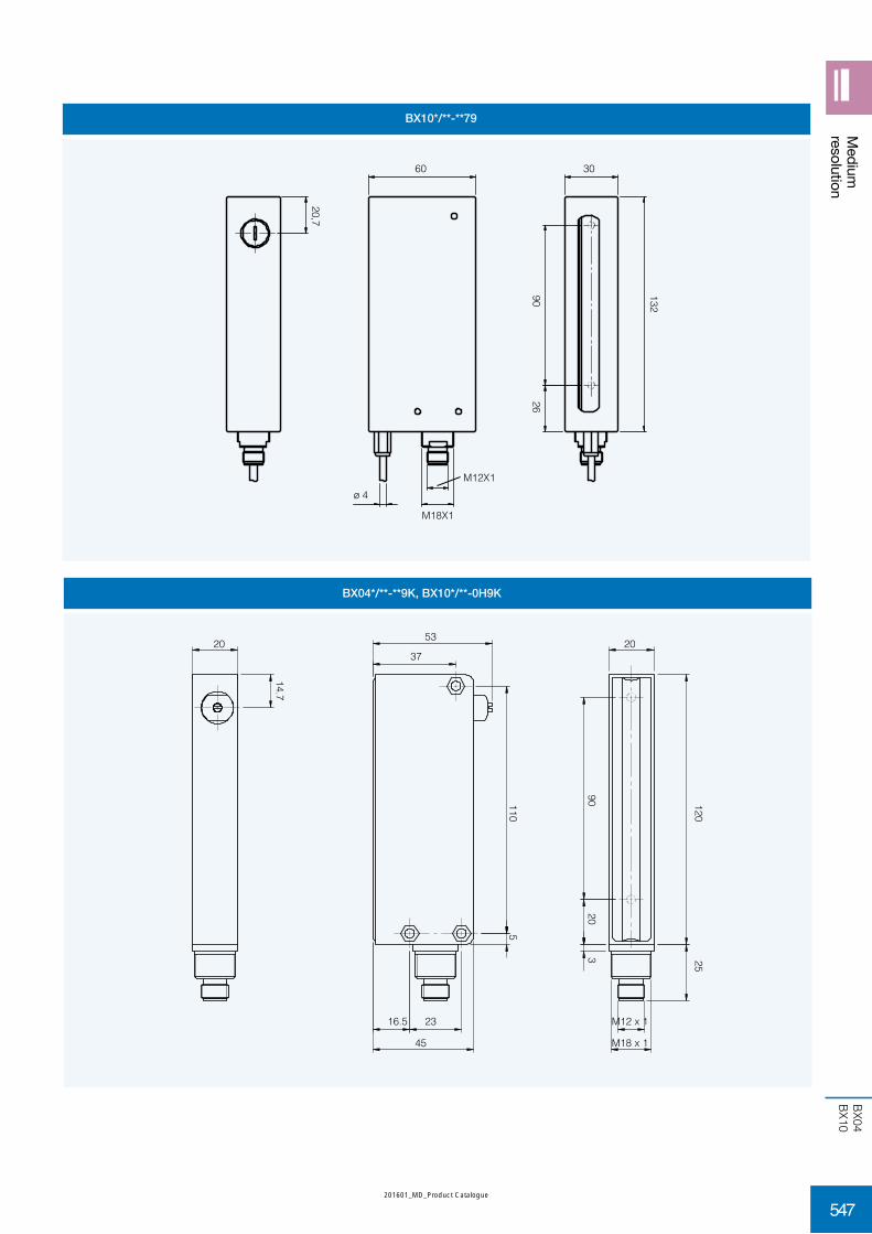
BX10*/**-**79
BX04*/**-**9K, BX10*/**-0H9K
60
20,7
ø 4
2690 132
30
M18X1
M12X1
Medium
resolution
110
16.5 23
45
5
320
90 12025
M12 x 1
M18 x 1
20
14.7
53
3720
547
BX04 BX10
201601_MD_Product Catalogue

BX04*/**-**AT, BX10*/**-**AT
dimensions (mm)
20
14.7
53
37
110
16.5 23
45
5
320
90
20120
24
ø 7.9
M18 x 1
548
BX80
201601_MD_Product Catalogue

/ -A
A
2
1
BX80 P 0BX80
1
SE
B
345
1
PN00
2AH
6X
3E
2D
H
9K
IP69K
High resolution cubic housingarea sensor
BX80 series
features
web contents
• Controlledheightt70mm
• Operatingdistanceupto2m
• Microprocessorbasedcircuit
• Sensitivityadjustment
• Strongcubichousing
• Specialversionwithmetallicenclosureforhigh-dutyuse
• ProtectiondegreeIP67
• Completeprotectionagainstelectricaldamages
• Applicationnotes
• Photos
• Catalogue/Manuals
code description
High resolution area sensor
Receiver for object detection with limited crossed beam, logic output, NO/NC selectable
Receiver for object detection with extended crossed beam, logic output, NO/NC selectable
Range 2 m, resolution ø 5-6 mm, response time 10 ms
Range 1.5 m, resolution ø 5-6 mm, response time 10 ms
Range 1 m, resolution ø 5-6 mm, response time 3 ms
Range 0.6 m, resolution ø 3-6 mm, response time 2 ms
Range 0.25 m, resolution ø 2 mm, response time 2 ms
NPN output
Sender
PBT standard body, with PC optic window
PBT standard body, with PC optic window + aluminium enclosure with air cooling system
PBT standard body, with PC glass optic window
PNP output
series
output
range
cable /connector
function
Emitter without sensitivity adjustment
Emitter with sensitivity adjustment
housing
version
M12 male connector
Standard version
All logic output receivers, 100 ms delay on dark/light commutation of logic output
All the codes with 1 position 3, increased reading distance to 2.5 m
Cable 2 m
BX80S/50-0H3E, BX80B/0*-0H3E special version for envelopes detection with the follow spec.: operating distance = 200-500 mm; response time = 10 ms; minimum envelope dimension = 1x70 mm
High resolutioncubic housing
Models with IP69K protection
ANAT
ATEX models 3 GD
ATEX models 2 GD
warranty
warranty
549
BX80
201601_MD_Product Catalogue

available models
PBT standard body with PC optic window receiver
area(mm)
response time(ms)
distance distance(mm)
emitter PNP NO/NC NPN NO/NC
70
10
0...2 m Ø 6BX80S/10-0H
BX80A/1P-0H BX80A/1N-0H
0.3...2 m Ø 5 BX80B/1P-0H BX80B/1N-0H
0...1.5 m Ø 6BX80S/20-0H
BX80A/2P-0H BX80A/2N-0H
0.3...1.5 m Ø 5 BX80B/2P-0H BX80B/2N-0H
30...1 m Ø 6
BX80S/30-0HBX80A/3P-0H -
0.5...1 m Ø 5 BX80B/3P-0H -
2
30...600 mm Ø 6BX80S/40-0H
BX80A/4P-0H -
550...660 mm Ø 3 BX80B/4P-0H -
90...250 mm Ø 2 BX80S/50-0H BX80A/5P-0H -
10 200...500 mm 1 X 70 BX80S/50-0H3E BX80A/5P-0H -
PBT standard body with PC optic window + aluminium enclosure receiver
area(mm)
response time(ms)
distance resolution(mm)
emitter PNP NO/NC
70
10
0...2 m Ø 6BX80S/10-1H
BX80A/1P-1H
0,3...2 mØ 5
BX80B/1P-1H
0.3...2.5 m BX80S/10-1H6X BX80B/1P-1H6X
0...1.5 m Ø 6BX80S/20-1H
BX80A/2P-1H
0.3...1.5 m Ø 5 BX80B/2P-1H
30...1 m Ø 6
BX80S/30-1HBX80A/3P-1H
0.5...1 m Ø 5 BX80B/3P-1H
2 30...600 mm Ø 6 BX80S/40-1H BX80A/4P-1H
PBT standard body, glass optic window receiver
area(mm)
response time(ms)
distance(m)
resolution(mm)
emitter PNP NO/NC
7010
0...2 Ø 6BX80S/10-2H
BX80A/1P-2H
0.3...2Ø 5
BX80B/1P-2H
0.3...2.5 BX80S/10-2H6X BX80B/1P-2H6X
0...1.5 Ø 6BX80S/20-2H
BX80A/2P-2H
0.3...1.5 Ø 5 BX80B/2P-2H
3 0...1 Ø 6 BX80S/30-2H BX80A/3P-2H
High resolutioncubic housing
550
BX80
201601_MD_Product Catalogue

PBT standard body, glass optic window receiver
area(mm)
response time(ms)
distance resolution(mm)
emitter PNP NO/NC
70
30...1 m Ø 6
BX80S/30-2HBX80A/3P-2H
0.5...1 m Ø 5 BX80B/3P-2H
230...600 mm Ø 6 BX80S/40-2H BX80A/4P-2H
90...250 mm Ø 2 BX80S/50-2H BX80A/5P-2H
10 200...500 mm 1 X 70 BX80B/50-2H3E BX80A/5P-2H
Models with cable exit (2 m): replace H with A in the code (BX80*/**-*H becomes BX80*/**-*A)
technical specification
BX80*/1*-** BX80*/2*-** BX80*/3*-**
2 m 1,5 m 1 m
max. 10 ms max. 3 ms
70 mm
126 mm
ø 6 mm (BX80A/*), ø 5 mm (BX80B/*)
0 (BX80A/*), 300 mm (BX80B/1 e BX80B/2), 500 mm (BX80B/3)
max.15%
5 %0/20% of the nominal sensing distance Sn
12-24 Vcc (standard)
10 %
50 mA (receiver), 100 mA (emitter)
100 mA max10 μA (at max operating voltage)
1.2 V max. (IL = 100 mA)NPN or PNP - NO/NC selectable
PNP NO/NC selectableM12 4 pin connector cable 2 m,M12 5 pin connector cable 2 m (BX80D/*)
2° (at nominal distance Sn)
3° (emitter) - 6° (receiver) at Sn distance
infrared (880 nm)500 ms
reversal polarity and voltage transient
short circuit (auto reset)-25°...+50°C (without freeze)
-40°...+80°C10% Sr
1.500 lux max. (incandescent lamp), 4.500 lux max. (sunlight)
IP67 (IP69K 9K version)
green (supply), red (alarm sync.), yellow (area state)green (supply), red (alignment), yellow (output state)
PBT (PC 9K version)PC
25 Nm max.
260...300 g connector / 800..820 g cable
nominal sensing distance
response time
controlled height
n° of beamsbeam pitch
minimum detectable object
minimum operating distance
hysteresisrepeatibilitytolerance
operating voltage
ripple
no-load supply currentload current
leakage currentvoltage drop
output type
connection
excess gain
angular displacement
emissionpower on delay
power supply protections
output protections
operating temperature rangestorage temperature
temperature drift
external light
IP mechanical protection
emitter LED
receiver LED
housing material
lens materal
tightening torque
wight (approximate)
High resolutioncubic housing
551
BX80
201601_MD_Product Catalogue
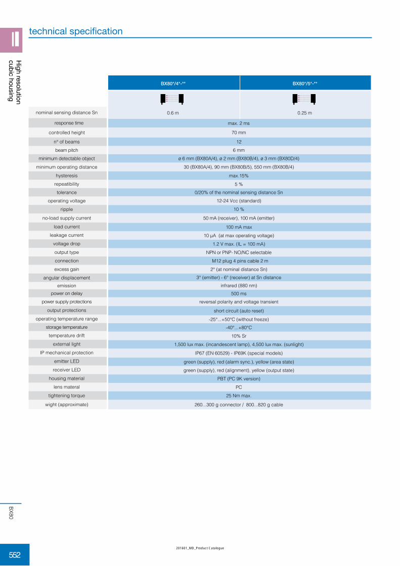
technical specification
BX80*/4*-** BX80*/5*-**
0.6 m 0.25 m
max. 2 ms
70 mm
126 mm
ø 6 mm (BX80A/4), ø 2 mm (BX80B/4), ø 3 mm (BX80D/4)
30 (BX80A/4), 90 mm (BX80B/5), 550 mm (BX80B/4)
max.15%
5 %0/20% of the nominal sensing distance Sn
12-24 Vcc (standard)
10 %
50 mA (receiver), 100 mA (emitter)
100 mA max10 μA (at max operating voltage)
1.2 V max. (IL = 100 mA)NPN or PNP- NO/NC selectable
M12 plug 4 pins cable 2 m2° (at nominal distance Sn)
3° (emitter) - 6° (receiver) at Sn distanceinfrared (880 nm)
500 msreversal polarity and voltage transient
short circuit (auto reset)
-25°...+50°C (without freeze)-40°...+80°C
10% Sr1,500 lux max. (incandescent lamp), 4,500 lux max. (sunlight)
IP67 (EN 60529) - IP69K (special models)
green (supply), red (alarm sync.), yellow (area state)green (supply), red (alignment), yellow (output state)
PBT (PC 9K version)PC
25 Nm max.
260...300 g connector / 800...820 g cable
nominal sensing distance Sn
response time
controlled height
n° of beamsbeam pitch
minimum detectable object
minimum operating distance
hysteresisrepeatibilitytolerance
operating voltage
ripple
no-load supply current
load currentleakage current
voltage drop
output type
connection
excess gain
angular displacementemission
power on delaypower supply protections
output protections
operating temperature rangestorage temperature
temperature drift
external light
IP mechanical protection
emitter LED
receiver LED
housing material
lens materal
tightening torque
wight (approximate)
High resolutioncubic housing
552
BX80
201601_MD_Product Catalogue

34
21
4 3
1 2
34
21
4 3
1 2
SYNC (+)
SYNC (-)
SYNC
OUT
WH
BK
BU
BN
- -
+ +
+
BN/1
BK/4
BU/3
WH/2
12 - 24DC
SYNC +
SYNC -
LOAD
BN/1
BK/4
BU/3
WH/2
- -
+ +
-
BN/1
BK/4
BU/3
WH/2
12 - 24DC
SYNC +
SYNC -
LOAD
BN/1
BK/4
BU/3
WH/2
Emitter Receiver Emitter Receiver
BX80*/**-**
emitter
plug
electrical diagrams of the connections
NPN output PNP output
dimensions (mm)
white
black
blue
brown
receiver
14.7
20
1105
36
2315.544
1.4
12025
M12 x 1
M18 x 1
323.5
66
1.4
12024
ø 5M18 x 1
323.5
99
supply (-)
supply (+)
supply (-)
supply (+)
Maximum synchronism cable length : 10 m.
red LEDyellow LED
High resolutioncubic housing
553
BX80
201601_MD_Product Catalogue

BX80*/**-1H
BX80*/**-0H9K
dimensions (mm)
19
60
132
30 601.4
20.7
M12 x 1
M18 x 1
29.566
ø 4 M18 x 1
18132
ø 4 ø 5
High resolutioncubic housing
20
14.7
36
5110
15.5 2344
8.2 1.4
M18X1M12X1
25120
366
23.5
554
BX80
201601_MD_Product Catalogue

BX80*/**-AT
diagnostics
(1) By free area
state conditions check
stable on supply is present and stable -
unstable on supply is present but not stable supply
off no supply or voltage lower than 8Vdc supply
full on no alignment alignment (1)
light on partial alignment or short signal orientamento (1)
off correct alignment and sufficient signal -
blinking on receiver does not function correctly or output short circuit wiring or failure
on output in ON state -
off output in OFF state -
stable on supply is present and stable -
unstable on supply is present but not stable supply
off no supply or voltage lower than 8Vdc supply
off synchronism property received -
on syncronism is not received or emitted wiring or failure
on engaged area or uncorrect alignment alignment (1)
off free area or correct alignment -
LED
GREEN receiverSupply
RED receiverAllignment
YELLOW receiver Supply
GREEN emitterSupply
RED emitterSync. alam
YELLOW emitterArea state
High resolutioncubic housing
20
110
3652 1.4
66
15.544
24120
23 ø 7.9M18 x 1
23.535
14.7
555
BX80
201601_MD_Product Catalogue

notes
556
CX0
201601_MD_Product Catalogue
/ -1ECX0 P 05 016CX0
R V
E
RPB0510016
01
V032
1
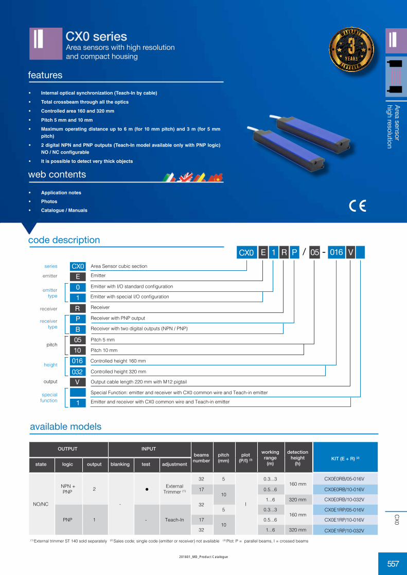
Area sensors with high resolution and compact housing
CX0 series
features
web contents• Applicationnotes
• Photos
• Catalogue/Manuals
code description
Area Sensor cubic section
Emitter
Emitter with special I/O configuration
Receiver
Receiver with PNP output
Receiver with two digital outputs (NPN / PNP)
Emitter with I/O standard configuration
Pitch 10 mm
Controlled height 160 mm
Controlled height 320 mm
Output cable length 220 mm with M12 pigtail
Special Function: emitter and receiver with CX0 common wire and Teach-in emitter
Pitch 5 mm
series
emitter
receiver type
receiver
height
pitch
special function
output
Area sensorhigh resolution
emitter type
• Internalopticalsynchronization(Teach-Inbycable)
• Totalcrossbeamthroughalltheoptics
• Controlledarea160and320mm
• Pitch5mmand10mm
• Maximumoperatingdistanceupto6m(for10mmpitch)and3m(for5mmpitch)
• 2digitalNPNandPNPoutputs(Teach-InmodelavailableonlywithPNPlogic)NO/NCconfigurable
• Itispossibletodetectverythickobjects
available models
(1) External trimmer ST 140 sold separately (2) Sales code; single code (emitter or receiver) not available (3) Plot: P = parallel beams, I = crossed beams
KIT (E + R) (2)
CX0E0RB/05-016V
CX0E0RB/10-016V
CX0E0RB/10-032V
CX0E1RP/05-016V
CX0E1RP/10-016V
CX0E1RP/10-032V
OUTPUT INPUTbeamsnumber
pitch(mm)
plot(P/I) (3)
workingrange
(m)
detection height
(h)state logic output blanking test adjustment
NO/NC
NPN + PNP 2
-
External Trimmer (1)
32 5
I
0.3...3160 mm
1710
0.5...6
321...6 320 mm
PNP 1 - Teach-In
5 0.3...3160 mm
1710
0.5...6
32 1...6 320 mm
Emitter and receiver with CX0 common wire and Teach-in emitter
warranty
warranty
557
CX0
201601_MD_Product Catalogue

CX1E*R*/**-***
0.3 ... 6 m (beam pitch 10 mm) 0.3... 3 m (beam pitch 5 mm)
850 nm (beam pitch 5mm) 880 nm (beam pitch ≥10mm)
16.8...30 Vdc
< 1.2 Vpp1...1.5 W1...1.5 W
1 x PNP, 1 x NPN
< 100 mA
< 1.5 V @ 100 mA280 Ω
≤ 10 μA
< 0.7 μF200 ms
< 15 s
< 17 ms-10°C...55°C-25°C...60°C
IEC EN 60947-5-2IEC EN 60947-5-2
IP67
95% max (no condensation)IEC EN 60947-5-2IEC EN 60947-5-2
< 20 m
1 x M12, 4 poles, male (CX1E), 1 x M12, 5 poles, male (CX1R)
painted aluminium RAL5002PMMA
nominal sensing distance
emission
operating voltage
ripple power consumption (receiver) power consumption (emitter)
output
output current
output voltage dropminimum load resistance
leakage current
tolerated capacitive load
power on delay
Teach-In
response timeoperating temperature
storage temperature
artificial light rejection
ambient light rejection
IP mechanical protection
humidityvibrations
shocks
cable length
connectors / cables
housing materialoptic materials
technical specifications
available models
(1) External trimmer ST 140 sold separately (2) Sales code; single code (emitter or receiver) not available 3) Plot: P = parallel beams, I = crossed beams
OUTPUT INPUTbeamsnumber
pitch(mm)
plug(P/I) (3)
workingrange
(m)
detection height(mm)state logic output blanking test adjustment
NO/NC NPN + PNP 2 -
External Trimmer (1)
335
I0.3...3
16065
P320
97 48017
10
I
0.3...6
16033 32049
P
48065 64081 80097 960
KIT (E + R)
CX1E0RB/05-016VCX1E0RB/05-032VCX1E0RB/05-048VCX1E0RB/10-016VCX1E0RB/10-032VCX1E0RB/10-048VCX1E0RB/10-064VCX1E0RB/10-080VCX1E0RB/10-096V
Area sensorhigh resolution
562
CX1
201601_MD_Product Catalogue

CX1/**-**
h (mm) 160 320 480 640 800 960
H (mm) 169 329 489 649 809 969
CX1E0/**-**-**
34
21
4 3
1 2
supply (+)
Test
Trimmer ext.
supply (-)
CX1RB/**-**-**
BN
BK
RD
GY
BU
WH
BN (Power) 0V24 VDC
BU (Common)
BK (Test)
WH (Trimmer)
Test
1
3
4
2
BN (Power) 0V24 VDC
BU (Common)
BK (PNP OUT)
WH (NPN OUT)
LOAD
1
3
4
2GY (NC/NO)
5
LOAD
NONONC
electric diagrams of the connections
plugs
brown
black
red
gray
blue
white
emitter with external trimmer emitter with Teach-In input
emitter with external trimmer emitter with Teach-In input
34
21
4 3
1 2
supply (+)
PNP out
NPN out
supply (-)
5 NC / NO
Area sensorhigh resolution
dimensions (mm)
Hh
11
4.5
p
4,.
35
20
9.5
8.5H (barrier height) = h (controlled height) + 9 mm
beams step(mm)
resolution (1)
(mm)qa 17 beams qa 32 beams
crossed (2)5 2,5 -
80%10 5 80%
MDO (Minimum Detectable Object)
(1) = Resolution detected with ST140(2) = The optics cross beam allows detection of objects with a very small diameter or very thin (such as a sheet of paper or an envelope). For those targets with small diameter, the detecting resolution is less effective exactly in the centre between Emitter and Receiver (see Resolution) as well as at the ends of detection area (near to the sensors); the mentioned detection is obtained in the central area Qa with a width equal to a certain % of the distance between the 2 sensors.
crossed-beam 5+1+5
1
2
3
4
5
6
7
8
9
range (100%)Qa%Qb%
563
CX1
201601_MD_Product Catalogue

description
4 pcs. kit antivibration basement for barriers with 150 mm protected height
8 pcs. kit antivibration basement for barriers with protected height from 1,500 mm to 1,050 mm
code
ST4V S
ST8V S
description
power connector M12, 4 wires, female, axial, cable 5 m PVC
power connector M12, 4 wires, female, axial, cable 10 m PVC
power connector M12, 4 wires, female, axial, cable 15 m PVC
power connector M12, 4 wires, female, axial, cable 5 m PUR
power connector M12, 4 wires, female, axial, cable 10 m PUR
power connector M12, 4 wires, female, axial, cable 15 m PUR
power connector M12, 5 wires, female, axial, cable 5 m PUR
power connector M12, 5 wires, female, axial, cable 10 m PUR
power connector M12, 5 wires, female, axial, cable 15 m PUR
code
CD12M/0B-050A1
CD12M/0B-100A1
CD12M/0B-150A1
CD12M/0B-050A5
CD12M/0B-100A5
CD12M/0B-150A5
CD12M/0H-050A5
CD12M/0H-100A5
CD12M/0H-150A5
accessory for external adjustment ST 140
accessories fixing kit ST151
T insert, two M5 nuts and split washers included L bracket
40
20 10
5.5
87
20.7
28
15
107.
5
1.5
10
M5
R 2.5
1.5 19.2
86.2
86.2200
57 R 4
27
ø 25
27
25
8
accessories not included
dimensions (mm)included with all models
Area sensorhigh resolution
564
CX1
201601_MD_Product Catalogue

/ -0ECX1 B 05 016CX1
R V
E
RB0510016
0
V
032048064080096
Area sensorhigh resolution
Area sensors with high resolution and compact housing with digital output
CX1 series
features
web contents• Applicationnotes
• Photos
• Catalogue/Manuals
code description
Area Sensor cubic section
Emitter
Receiver
Receiver with two digital outputs (NPN / PNP)
Emitter with I/O standard configuration
Pitch 10 mm
Controlled height 160 mm
Controlled height 320 mm
Output cable length 220 mm with M12 pigtail
Pitch 5 mm
series
emitter
receiver type
receiver
height
pitch
output
emitter type
Controlled height 480 mm
Controlled height 640 mm
Controlled height 800 mm
Controlled height 960 mm
• opticalsynchronization
• floatingcrossbeamwithfixedamplitude(5+1+5)
• areaheightcontrolledfrom160and320mm
• pitch5mmand10mm
• maximumoperatingdistanceupto6m(for10mmpitch)and3m(for5mmpitch)
• NPNandPNPdigitaloutputsNO/NCconfigurable
• foracorrectuseitisnecessarytomanuallyadjusttheemitter(accessoryST140)
warranty
warranty
561
CX1
201601_MD_Product Catalogue
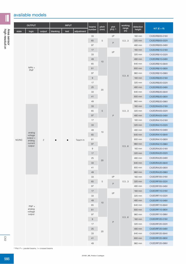
OUTPUT INPUT beamsnumber
pitch(mm)
plot(P/I) (1)
workingrange
(m)
detection height
state logic output blanking test adjustment
NO/NC
NPN + PNP
2 Teach-In
33
5
I/P
0.3...3
160 mm
65P
320 mm
97 480 mm
17
10
I/P
0.3...6
160 mm
33 320 mm
49
P
480 mm
65 640 mm
81 800 mm
97 960 mm
9
20
160 mm
17 320 mm
25 480 mm
33 640 mm
41 800 mm
49 960 mm
analog voltage output + analog current output
33
5 0.3...3
160 mm
65 320 mm
97 480 mm
17
10
0.3...6
160 mm
33 320 mm
49 480 mm
65 640 mm
81 800 mm
97 960 mm
9
20
160 mm
17 320 mm
25 480 mm
33 640 mm
41 800 mm
49 960 mm
PNP + analog voltage output
33
5
I/P
0.3...3
160 mm
65P
320 mm
97 480 mm
17
10
I/P
0.3...6
160 mm
33 320 mm
49
P
480 mm
65 640 mm
81 800 mm
97 960 mm
9
20
160 mm
17 320 mm
25 480 mm
33 640 mm
41 800 mm
49 960 mm
KIT (E + R)
CX2E0RB/05-016V
CX2E0RB/05-032V
CX2E0RB/05-048V
CX2E0RB/10-016V
CX2E0RB/10-032V
CX2E0RB/10-048V
CX2E0RB/10-064V
CX2E0RB/10-080V
CX2E0RB/10-096V
CX2E0RB/20-016V
CX2E0RB/20-032V
CX2E0RB/20-048V
CX2E0RB/20-064V
CX2E0RB/20-080V
CX2E0RB/20-096V
CX2E0RA/05-016V
CX2E0RA/05-032V
CX2E0RA/05-048V
CX2E0RA/10-016V
CX2E0RA/10-032V
CX2E0RA/10-048V
CX2E0RA/10-064V
CX2E0RA/10-080V
CX2E0RA/10-096V
CX2E0RA/20-016V
CX2E0RA/20-032V
CX2E0RA/20-048V
CX2E0RA/20-064V
CX2E0RA/20-080V
CX2E0RA/20-096V
CX2E0RF/05-016V
CX2E0RF/05-032V
CX2E0RF/05-048V
CX2E0RF/10-016V
CX2E0RF/10-032V
CX2E0RF/10-048V
CX2E0RF/10-064V
CX2E0RF/10-080V
CX2E0RF/10-096V
CX2E0RF/20-016V
CX2E0RF/20-032V
CX2E0RF/20-048V
CX2E0RF/20-064V
CX2E0RF/20-080V
CX2E0RF/20-096V
available models
(1) Plot: P = parallel beams, I = crossed beams
Area sensorhigh resolution
566
CX2
201601_MD_Product Catalogue

CX2E*R*/**-***V
0.1 ... 3 m (beam pitch 5 mm) 0.3 ... 6 m (beam pitch 10 mm)
850 nm (beam pitch 5mm) 880 nm (beam pitch ≥10mm)
16.8...30 Vdc
< 1.2 Vpp1...2.5 W
1...3 W
1 x PNP, 1 x NPN (CX2E0RB); 1 x analog voltage output, 1 x analog current output (CX2E0RA); 1 x PNP, 1 X analog votlage output (CX2E0RF)
< 100 mA
< 1.5 V @ 100 mA280 Ω
≤ 10 μA
< 0.7 μF< 3 sec(1)
(0.5 x N beams) sec
((0.2 x (N beams - 1)) + 1) x 2 ms-10°C...55°C-25°C...60°C
IEC EN 60947-5-2IEC EN 60947-5-2
IP67
95% max (no condensation)IEC EN 60947-5-2IEC EN 60947-5-2
< 20 m
1 x M12, 4 poles, male (CX2E), 1 x M12, 8 poles, male (CX2R)alluminio verniciato RAL5002
PMMA
technical specifications
(1) Power on delay with blanking function: (1 x N beams) sec
nominal sensing distance
emission
operating voltage
ripple power consumption (receiver)
power consumption (emitter)
output
output current
output voltage dropminimum load resistance
leakage current
tolerated capacitive load
power on delay
Teach-In
response timeoperating temperature
storage temperature
artificial light rejection
ambient light rejection
IP mechanical protection
humidityvibrations
shocks
cable length
connectors / cables
housing material
optic materials
Area sensorhigh resolution
567
CX2
201601_MD_Product Catalogue

1 2
3
45
7
68
Teach g/f
Blank y/n
SYNC_1W
NO/NCANA_V
ANA_I Supply (+)
CX2RF/**-**-**
1 2
3
45
7
68
Teach g/f
Blank y/n
SYNC_1W
NO/NCPNP
ANA_V Supply (+)
receiver PNP with analog output V CX2RA/**-**-** receiver with analog output
Area sensorhigh resolution
Supply (-) Supply (-)
plugs
34
21
4 3
1 2
Supply (+)
Test
SYNC_1W
Supply (-)
1 2
3
45
7
68
Teach g/f
Blank y/n
SYNC_1W
NO/NCPNP out
NPN OUT
Supply (-)
Supply (+)
CX2E0/**-**-** emitter with test input CX2RB/**-**-** receiver with PNP and NPN output
beams step(mm)
resolution (1)
(mm)qa 17 beams qa 32 beams
crossed (2)5 2,5 -
93%10 5 93%
parallel
5 5
- -10 10
20 20
MDO (Minimum Detectable Object)
(1) = resolution detected with Teach Gross(2) = the optics cross beam allows detection of objects with a very small diameter or very thin (such as a sheet of paper or an envelope). For those targets with small diameter, the detecting resolution is less effective exactly in the centre between Emitter and Receiver (see Resolution) as well as at the ends of detection area (near to the sensors); the mentioned detection is obtained in the central area Qa with a width equal to a certain % of the distance between the 2 sensors.
crossed-beam 8+1+8
1
2
3
4
5
6
7
8
9
range (100%)Qa%Qb%
568
CX2
201601_MD_Product Catalogue

/ -0ECX2 B 05 016CX2
R V
E
RAB
0510
0
V
F
20016032048
080096
064
TP
Area sensors with high resolution and compact housing with digital and analogue output
CX2 series
Area sensorhigh resolution
features
web contents• Applicationnotes
• Photos
• Catalogue/Manuals
code description
• synchronizationbycable
• parallelbeamsandfloatingcrossbeamswithvariableamplitude
• controlledareafrom160and320mm
• pitch5mmand10mm
• maximumoperatingdistanceupto6m
• doubleNPNandPNPdigitaloutputs,NO/NCconfigurable
• 2analogueoutputs:CurrentandVoltage
• blankingfunctionavailable
Area Sensor cubic section
Emitter
Receiver
Receiver with two analogue outputs (voltage 0...10 V and current 4...20 mA)
Emitter with I/O standard configuration
Pitch 10 mm
Controlled height 160 mm
Controlled height 320 mm
Output cable length 220 mm with M12 pigtail
Analog reading last led TOP BEAM (CX2RA)
Pitch 5 mm
series
emitter
receiver type
receiver
height
pitch
special function
output
emitter type
Controlled height 480 mm
Controlled height 640 mm
Controlled height 800 mm
Controlled height 960 mm
Pitch 20 mm
Receiver with two digital outputs (NPN and PNP)
Receiver with one digital output PNP and one analogue output (voltage 0...10 V)
warranty
warranty
565
CX2
201601_MD_Product Catalogue

description
power connector M12, 4 wires, female, axial, cable 5 m PVC
power connector M12, 4 wires, female, axial, cable 10 m PVC
power connector M12, 4 wires, female, axial, cable 15 m PVC
power connector M12, 4 wires, female, axial, cable 5 m PUR
power connector M12, 4 wires, female, axial, cable 10 m PUR
power connector M12, 4 wires, female, axial, cable 15 m PUR
power connector M12, 8 wires, female, axial, cable 5 m PUR
power connector M12, 8 wires, female, axial, cable 10 m PUR
power connector M12, 8 wires, female, axial, cable 15 m PUR
code
CD12M/0B-050A1
CD12M/0B-100A1
CD12M/0B-150A1
CD12M/0B-050A5
CD12M/0B-100A5
CD12M/0B-150A5
CD12M/0X-050A5
CD12M/0X-100A5
CD12M/0X-150A5
Area sensorhigh resolution
accessories fixing kit ST151
descrizione
kit di 4 supporti antivibranti per modelli con altezza ottica di 150 mmkit di 8 supporti antivibranti per modelli con altezza ottica da 300 a 1050
mm
codice
ST4V S
ST8V S
description
4 pcs. kit antivibration basement for barriers with 150 mm protected height
8 pcs. kit antivibration basement for barriers with protected height from 1,500 mm to 1,050 mm
code
ST4V S
ST8V S
T insert, two M5 nuts and split washers included L bracket
40
20 10
5.5
87
2.7
28
15
107.
5
1.5
10
M5
R 2.5
1.5 19.2
accessoriesnot included
accessoriesincluded with all models
570
CX2
201601_MD_Product Catalogue

CX2E*R*/**-***V
0.1 ... 3 m (beam pitch 5 mm) 0.3 ... 6 m (beam pitch 10 mm)
850 nm (beam pitch 5mm) 880 nm (beam pitch ≥10mm)
16.8...30 Vdc
< 1.2 Vpp1...2.5 W
1...3 W
1 x PNP, 1 x NPN (CX2E0RB); 1 x analog voltage output, 1 x analog current output (CX2E0RA); 1 x PNP, 1 X analog votlage output (CX2E0RF)
< 100 mA
< 1.5 V @ 100 mA280 Ω
≤ 10 μA
< 0.7 μF< 3 sec(1)
(0.5 x N beams) sec
((0.2 x (N beams - 1)) + 1) x 2 ms-10°C...55°C-25°C...60°C
IEC EN 60947-5-2IEC EN 60947-5-2
IP67
95% max (no condensation)IEC EN 60947-5-2IEC EN 60947-5-2
< 20 m
1 x M12, 4 poles, male (CX2E), 1 x M12, 8 poles, male (CX2R)painted aluminium RAL5002
PMMA
technical specifications
(1) Power on delay with blanking function: (1 x N beams) sec
nominal sensing distance
emission
operating voltage
ripple power consumption (receiver)
power consumption (emitter)
output
output current
output voltage dropminimum load resistance
leakage current
tolerated capacitive load
power on delay
Teach-In
response timeoperating temperature
storage temperature
artificial light rejection
ambient light rejection
IP mechanical protection
humidityvibrations
shocks
cable length
connectors / cables
housing material
optic materials
Area sensorhigh resolution
567
CX2
201601_MD_Product Catalogue

available models
function optics adjust. check output moisture resistant
delay(ms)
distance(m)
emitter + receiver
14 axialNPN - NO
-
100
0,37...2
PNP - NO-
14 right angle
10014 axial
NPN - NC
14 right angle
-
PNP - NC
-
-
16 axial
NPN - NO
100
16 right angle
-
100
16 axialPNP - NO
- 16 right angle
16 axial
NPN - NC
16 right angle
-
model
NX14SR/XAN-A010
NX14SR/XAP-A000
NX14SR/XAP-C000
NX14SR/XAP-C010
NX14SR/XCN-AT10
NX14SR/XCN-C010
NX14SR/XCN-CT10
NX14SR/XCP-C000
NX16SR/XAN-A010
NX16SR/XAN-C000
NX16SR/XAN-C010
NX16SR/XAN-CT10
NX16SR/XAP-A010
NX16SR/XAN-C010
NX16SR/XCN-A010
NX16SR/XCN-AT10
NX16SR/XCN-C010
NX16SR/XCN-CT10
Special Area Sensors
572
NX
201601_MD_Product Catalogue

technical specification
NX**SR/***-*****
medium resolution area sensor with 16/14 optics, step 10 mm
0.37...2 m 880 nm (beam pitch ≥10mm)
infrared (880 nm), modulated
150 mm (16 optics) ; 132 mm (14 optics)370 mm
ø15 (1) / ø 7.5 (2) / ø 5 (3) mm
< 10%
10 – 26 Vdc
10%150 mA (emitter) – 25 mA (receiver)
100 mA
< 10 μA (a Vdc max.)2 V a 100 mA
NPN or PNP open collector, NO or NCcheck input500 μsec
7 ms< 85 ms (switch on delay)
100 ms (according to models)
polarity reversal - transient
short circuit (autoreset)-0 /+ 55 °C (without freeze)
1000 lux (incandescent lamp) 1500 lux (sunlight)
not defined
yellow (supply and emission active)red (signal level) – Yellow (output state active)
No housing. Mechanical and electrical protections of the PCB have to be submitted to the machine structure
With PCB connectors / Emitter, Conn. 3 MOLEX 22-05-7038 - Positive, Check, Common / Receiver, Conn. 1 MOLEX 22-05-7038 - Positive, Check, Common / Receiver, Conn. 2 MOLEX 22-05-7048 Positive, Check, Output, Common
157 x 36 x 18 mm (16 optics) - 140 x 36 x 18 mm (14 optics)
104 g
type
nominal sensing distance
emission
controlled heightminimum sensing distanceminimum detectable object
hysteresis
supply voltageripple
no-load supply current output current
leakage current
voltage dropoutput type
inputresponse time (Light/Dark)
response time (Light/Dark)
power on delay
output delay
power supply protections
output protection
temperature rangeinterference to external light
IP mechanical protection
emitter LED
receiver LED
housing material
connections
dimensions
weight (approximate)
(1) Guaranteed resolution everywhere in the detection area(2) Guaranteed resolution in the central part of the detection(3) As note (2), but with sensivity adjustment
Dark zones are parts of the detection area close to the emitter and receiver, their amplitude X is proportional to the distance D between the emitter and the receiver. X=0.06D.
Special Area Sensors
573
NX
201601_MD_Product Catalogue

Emettitore
+
-
Ricevitore
1
2
3
1
2
3
1
2
3
4
TEST
Con
n. 3
Con
n. 2
Con
n. 1
Emettitore Ricevitore
TEST
Con
n. 3
Con
n. 2
Con
n. 1
+
-
PNP uscita
NPN uscita
1
2
3
1
2
3
1
2
3
4
NX16SR/***_A***
electrical diagrams of the connections
Warnings regarding to electrostatic discharge (ESD)• disconnect the supply voltage before touching the device• discharge the electrostatic charges before touching the device • use metallic screws to install the device
dimensions (mm)
NPN output PNP output
135
7.9
38.4
ø 4
32.4
15
48.3
157
539
Special Area Sensors
574
NX
201601_MD_Product Catalogue
/ -16 SR
R
R
C
A
NXNX
14
0
NP
16
00T0
S
SR
A N AX
X
0A
0
C
10
0 00
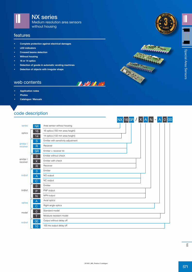
Medium resolution area sensorswithout housing
NX series
features
web contents• Applicationnotes
• Photos
• Catalogue/Manuals
• Completeprotectionagainstelectricaldamages
• LEDindicators
• Crossedbeamsdetection
• Withouthousing
• 16or14optics
• Detectionofgoodsinautomaticvendingmachines
• Detectionofobjectswithirregularshape
code description
Area sensor without housing
Emitter with sensitivity adjustment
Receiver
Emitter without check
Emitter with check
Receiver
Emitter
NO output
Emitter + receiver kit
Emitter
PNP output
NPN output
Axial optics
Right angle optics
NC output
series
emitter / receiver
emitter /receiver
output
optics16 optics (150 mm area height)
14 optics (132 mm area height)
output
optics
model
output
Standard model
Moisture resistant model
Output without delay off
100 ms output delay off
Special Area Sensors
warranty
warranty
571
NX
201601_MD_Product Catalogue

NX14SR/***_A***
dimensions(mm)
135
7 14.9
ø 4
32.4
1548.3
140.5
53937.1
Special Area Sensors
576
NX
201601_MD_Product Catalogue

notes
577
NX
201601_MD_Product Catalogue