Arduino Survival Guide Workshop Edition
38
1 Arduino Survival Guide Workshop Edition ~ Helping Your Arduino Survive You Ed Nisley • KE4ZNU [email protected] softsolder.com ~ Squidwrench June 2013
-
Upload
johanduraan9540 -
Category
Documents
-
view
227 -
download
3
Transcript of Arduino Survival Guide Workshop Edition
1
Arduino Survival GuideWorkshop Edition
~Helping Your Arduino
Survive You
Ed Nisley • [email protected]
softsolder.com~
SquidwrenchJune 2013

2
Bring This Stuff With You
Laptop (with Arduino board + USB cable!)
Arduino IDE installed & tested
Multimeter
Volt • Amp • Ohm (optional: Freq • Diode • Cap • Induct)
Two (or more!) meters = better
Scientific Calculator (√ power log engineering)
Power strip / short extension cord
Useful, but not absolutely essential
Solderless breadboard / ProtoScrewShield
Soldering iron & suchlike
3
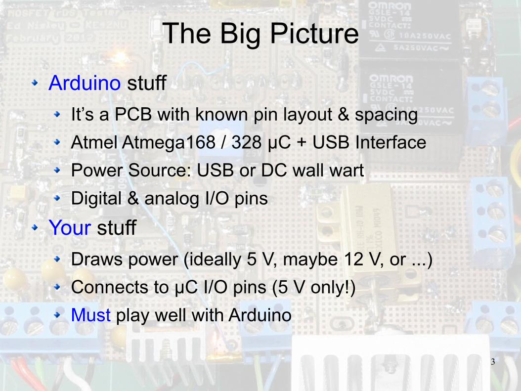
The Big Picture
Arduino stuff
It’s a PCB with known pin layout & spacing
Atmel Atmega168 / 328 μC + USB Interface
Power Source: USB or DC wall wart
Digital & analog I/O pins
Your stuff
Draws power (ideally 5 V, maybe 12 V, or ...)
Connects to μC I/O pins (5 V only!)
Must play well with Arduino
4
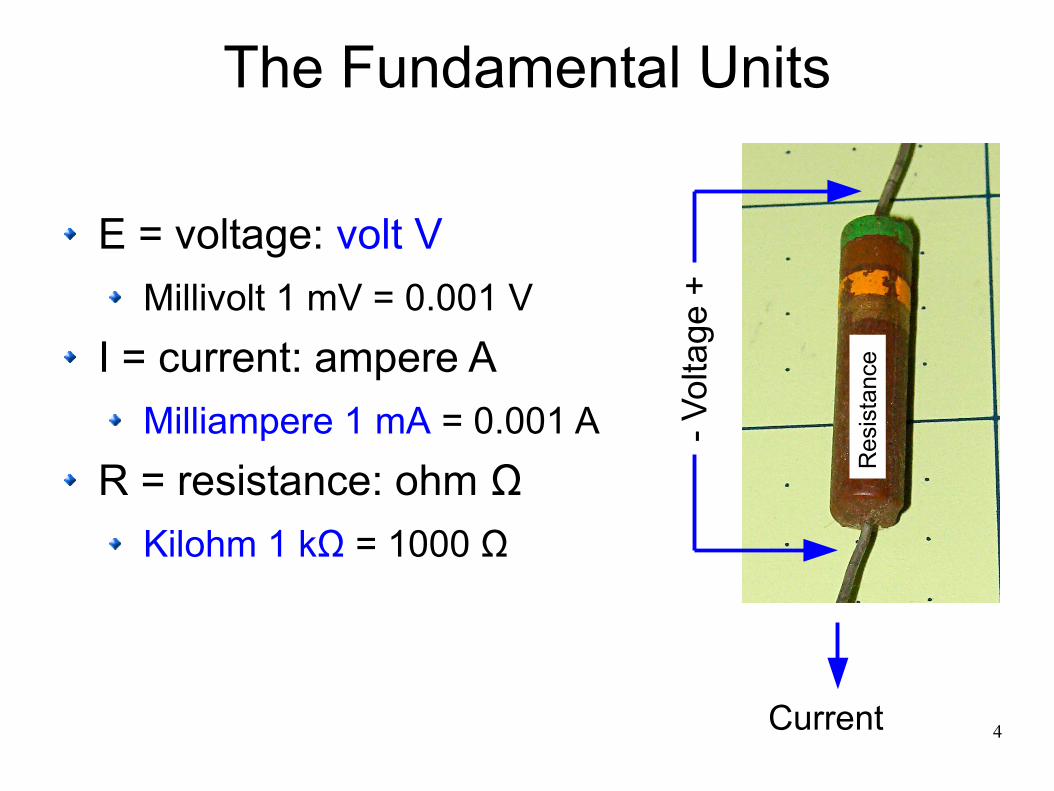
The Fundamental Units
E = voltage: volt V
Millivolt 1 mV = 0.001 V
I = current: ampere A
Milliampere 1 mA = 0.001 A
R = resistance: ohm Ω
Kilohm 1 kΩ = 1000 Ω
Current-
Vol
t age
+
Res
ista
nce

5
Lab: Measure Resistor Circuit
Set meter to Ω = ohms
Measure resistance
Set meter to V = volts
Measure voltage
Set meter to A = amps
(Re-plug leads?)
Measure current
(Re-plug leads?)

6
One Rule To Bind Them All
Ohm’s Law
I = E / R (know R, measure E, get current!)
E = I • R
R = E / I
Most useful with resistors = known resistance
You need a calculator and a multimeter ... now!
7
Lab: Verify Ohm’s Law
Using your measured values
Does measured voltage = (current x resistance)?
Does measured current = (voltage / resistance)?
Does measured resistance = (voltage / current)?
How close did you come?
Percentage vs. absolute error
What are the most accurate measurements?
8
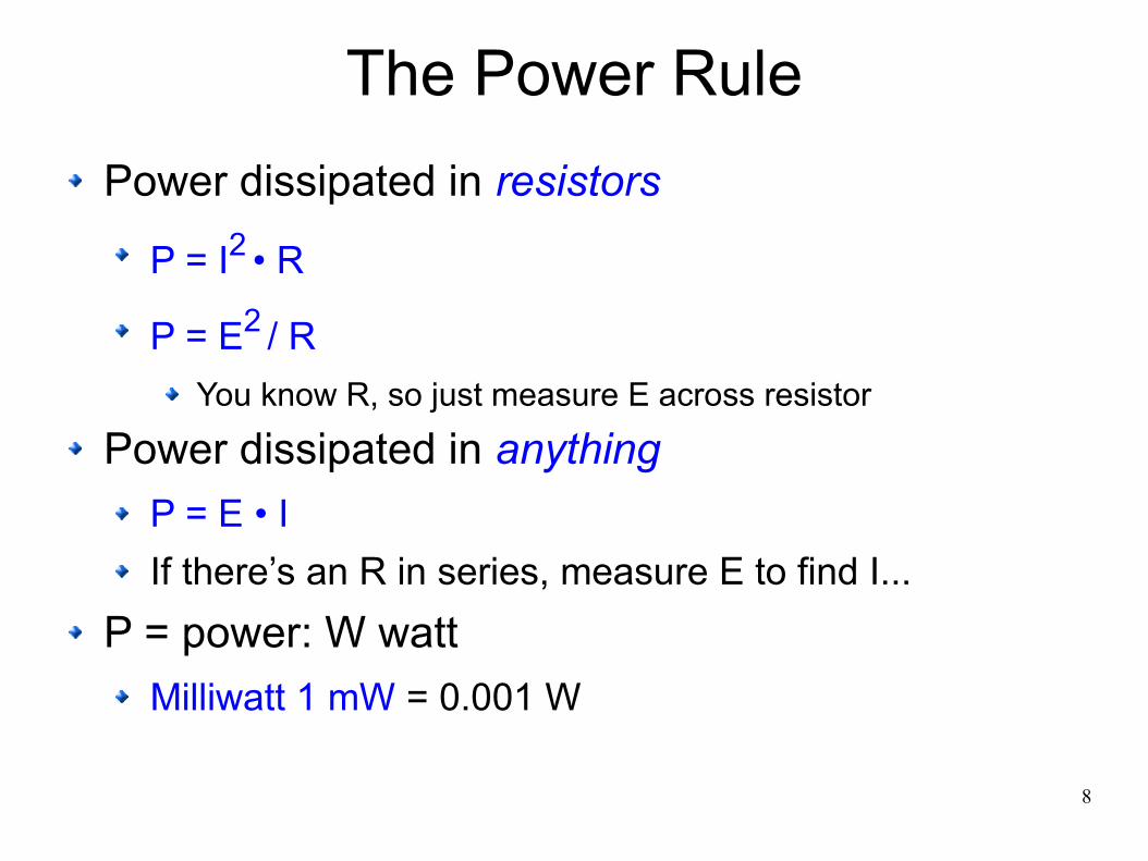
The Power Rule
Power dissipated in resistors
P = I2 • R
P = E2 / R
You know R, so just measure E across resistor
Power dissipated in anything
P = E • I
If there’s an R in series, measure E to find I...
P = power: W watt
Milliwatt 1 mW = 0.001 W
9
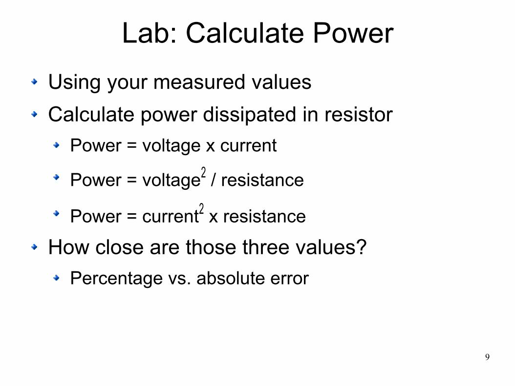
Lab: Calculate Power
Using your measured values
Calculate power dissipated in resistor
Power = voltage x current
Power = voltage2 / resistance
Power = current2 x resistance
How close are those three values?
Percentage vs. absolute error

10
Capacitance
C = capacitance: farad F
Millifarad1 mF = 0.001 F = 10-3 F
Microfarad1 μF = 0.000 001 F = 10 -6 F
Nanofarad1 nF = 0.000 000 001 F = 10 -9 F
Picofarad1 pF = 0.000 000 000 001 F = 10 -12 F
11
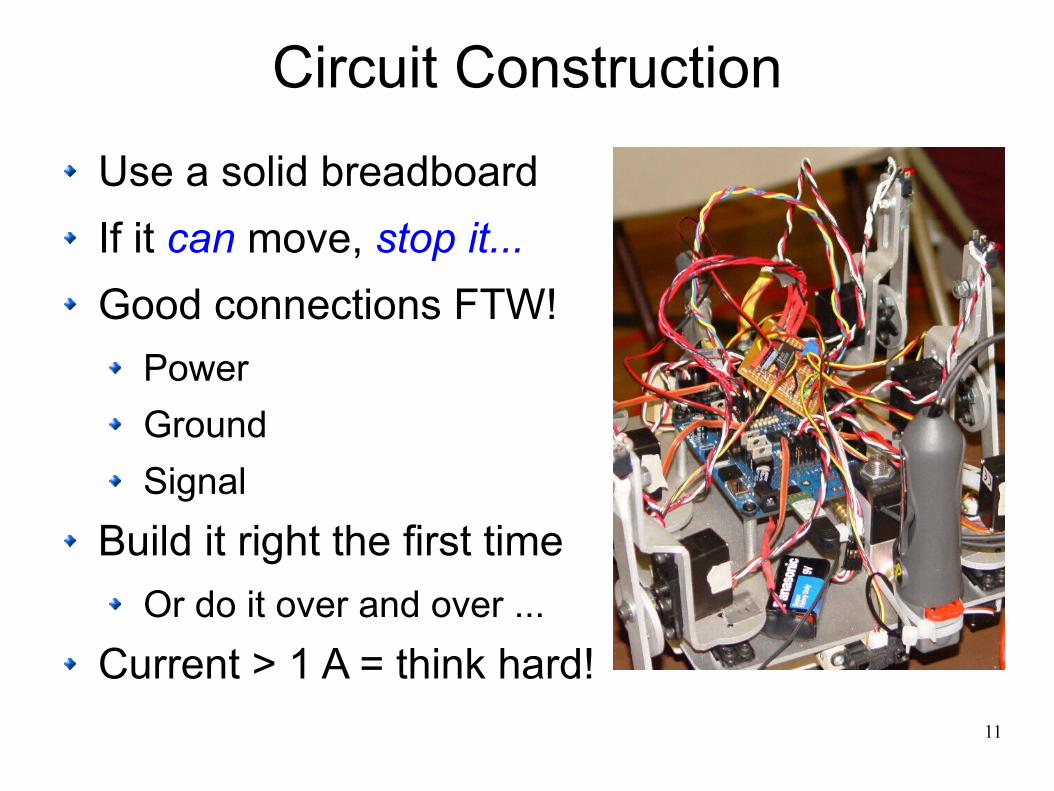
Circuit Construction
Use a solid breadboard
If it can move, stop it...
Good connections FTW!
Power
Ground
Signal
Build it right the first time
Or do it over and over ...
Current > 1 A = think hard!

12
Power Supply
USB Supply ≠ 5.0 V
Measure actual voltage!
Draw < 200 mA from portMax ≈ 500 mA, usually
Wall Wart VEXT
≤ 12 V
Loose wire? μC dies > 5 V!
Less heat @ VEXT
= 9 V
Keep regulator < 500 mW
Power P = (VEXT
- 5) * I
http://arduino.cc/en/Main/ArduinoBoardUno

13
Ground (a.k.a. Common)
Reference = 0 V
Sum of all currents
AC + DC Signals
Difficult to get right
High current = trouble
Vital for good signals
Glitches & intermittents
Impossible to fix later
Daisy chain = death
http://softsolder.com/2012/02/23/mosfet-rds-pcb/
MOSFET RDS(on)
TesterPCB has four ground planes
14
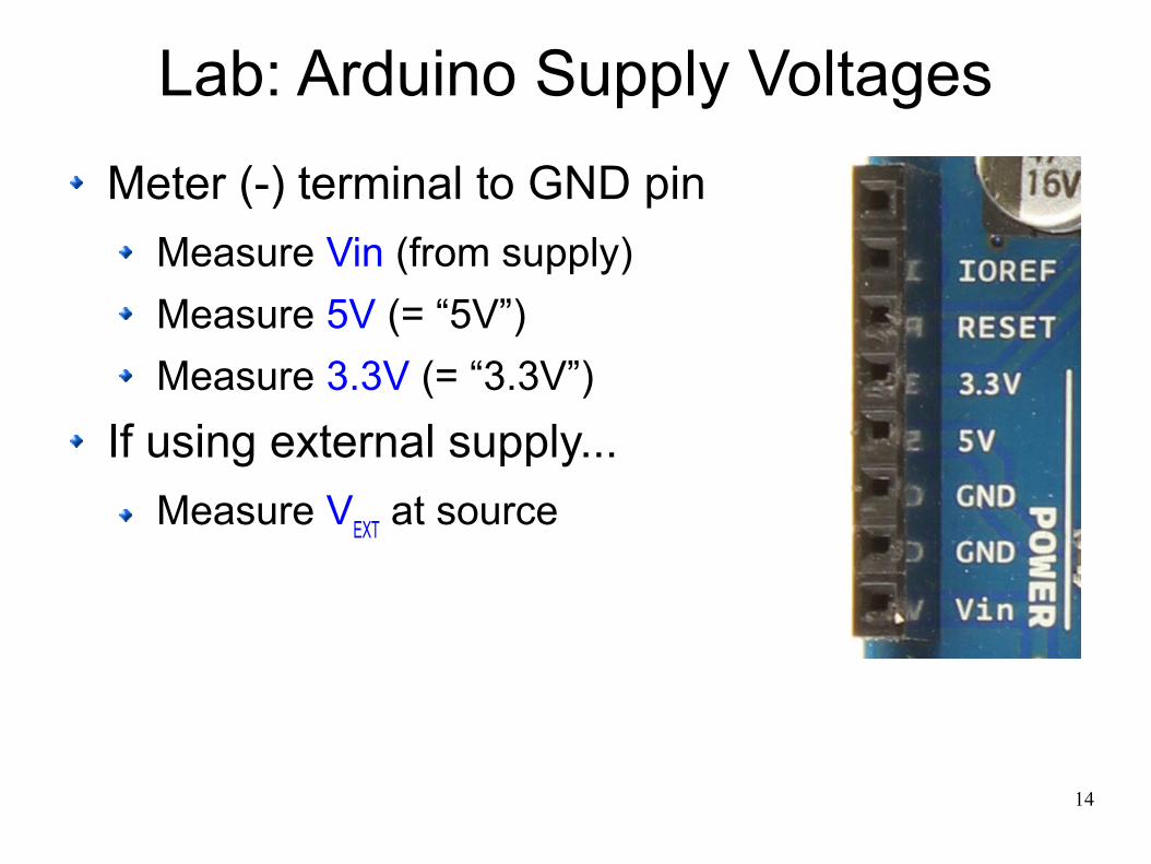
Lab: Arduino Supply Voltages
Meter (-) terminal to GND pin
Measure Vin (from supply)
Measure 5V (= “5V”)
Measure 3.3V (= “3.3V”)
If using external supply...
Measure VEXT
at source

15
Lab: Arduino Supply Current
Measure current from supply
USB needs inline tap
Wall wart can be cut & spliced

16
Lab: Calculate Arduino Power
Total power“Vin” x supply current
Regulator power(“Vin” – “5V”) x supply current
Is it < 500 mW?
Board power“5V” x supply current
Compare all those powers
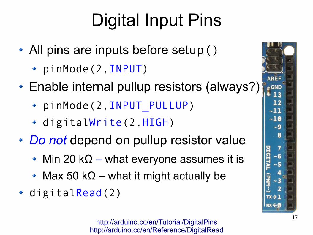
17
Digital Input Pins
All pins are inputs before setup()
pinMode(2,INPUT)
Enable internal pullup resistors (always?)
pinMode(2,INPUT_PULLUP)
digitalWrite(2,HIGH)
Do not depend on pullup resistor value
Min 20 kΩ – what everyone assumes it is
Max 50 kΩ – what it might actually be
digitalRead(2)
http://arduino.cc/en/Tutorial/DigitalPinshttp://arduino.cc/en/Reference/DigitalRead

18
Lab: Measure Arduino Pullup
Insert 47 kΩ resistor: D12 - GND
pinMode(12,INPUT_PULLUP)
Modify Blink example!
Measure V across resistor
Compute:
Current through resistor: I = E / R
Voltage across pullup: “5V” - V
Pullup resistanceKnow voltage & current: R = E / I
Is pullup ≥ 20 kΩ and ≤ 50 kΩ?

19
Digital Output Pins
Configure pins for output in setup()
pinMode(2,OUTPUT)
Outputs HIGH = 5 V or LOW = 0 V
Depends on load: measure!
Current ≤ 40 mA / pin = absolute max
Happiness ↑↑ for current ≤ 20 mA
Enough for one standard LED...
Maximum total μC current ≤ 200 mA
Draw much less than that: ≤ 100 mA max
http://arduino.cc/en/Tutorial/DigitalPinshttp://arduino.cc/en/Reference/DigitalWrite

20
Additional Digital I/O Pins!
Reconfigure Analog Input pins
pinMode(A0,INPUT_PULLUP)
pinMode(A0,OUTPUT)
The usual digital functions
digitalWrite(A0,LOW)
digitalRead(A0)
No analog output
analogWrite(A0,128)

21
Switch Inputs
Connect input pin to ground
This kills output pins = HIGH
Add 1 kΩ series R for protection?
Enable internal pullup
pinMode(12,INPUT_PULLUP)
Add external pullup ≈ 10 kΩ
Pin states track voltages
Closed = pushed = LOW = false
Open = released = HIGH = true
http://arduino.cc/en/Reference/DigitalRead

22
Switch Contact Bounce
Glitches galore!
Time scale = 10 ms/div
Unpredictable events
Add parallel C = bad
Resonant with stray L
Voltage spikes!
Use e.g. Bounce library
Don’t roll your own
Plan for the worst case
https://en.wikipedia.org/wiki/Switch#Contact_bouncehttp://arduino.cc/playground/Code/Bounce
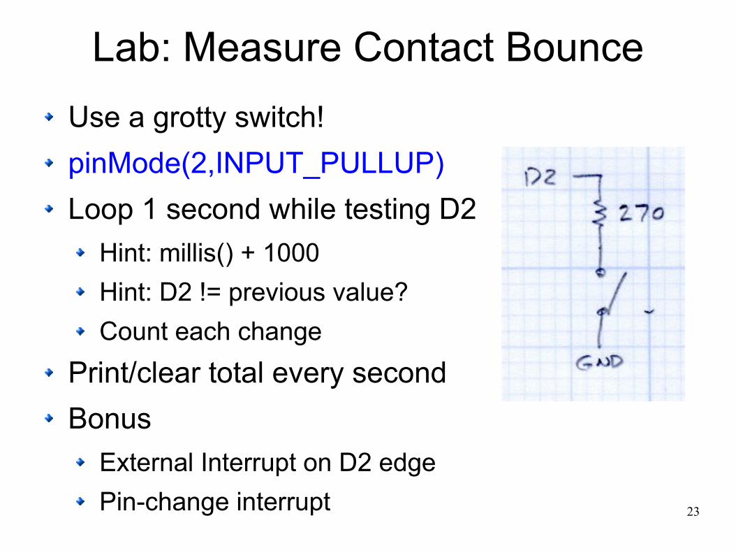
23
Lab: Measure Contact Bounce
Use a grotty switch!
pinMode(2,INPUT_PULLUP)
Loop 1 second while testing D2
Hint: millis() + 1000
Hint: D2 != previous value?
Count each change
Print/clear total every second
Bonus
External Interrupt on D2 edge
Pin-change interrupt

24
“Analog” Output
It’s not analog, it’s digital ...
PWM = Pulse Width Modulation
Output pins 3, 5, 6, 9, 10, 11 only
analogWrite(3,100)
Minimum = 0 → 0 V
Maximum = 255 → 5 V (depends on load)
0 < “analog PWM” < 255 → pulses (duh)
PWM frequency ≈ 488 & 976 Hz
Direct LED drive works fine
http://arduino.cc/en/Reference/AnalogWritehttp://arduino.cc/en/Tutorial/PWM
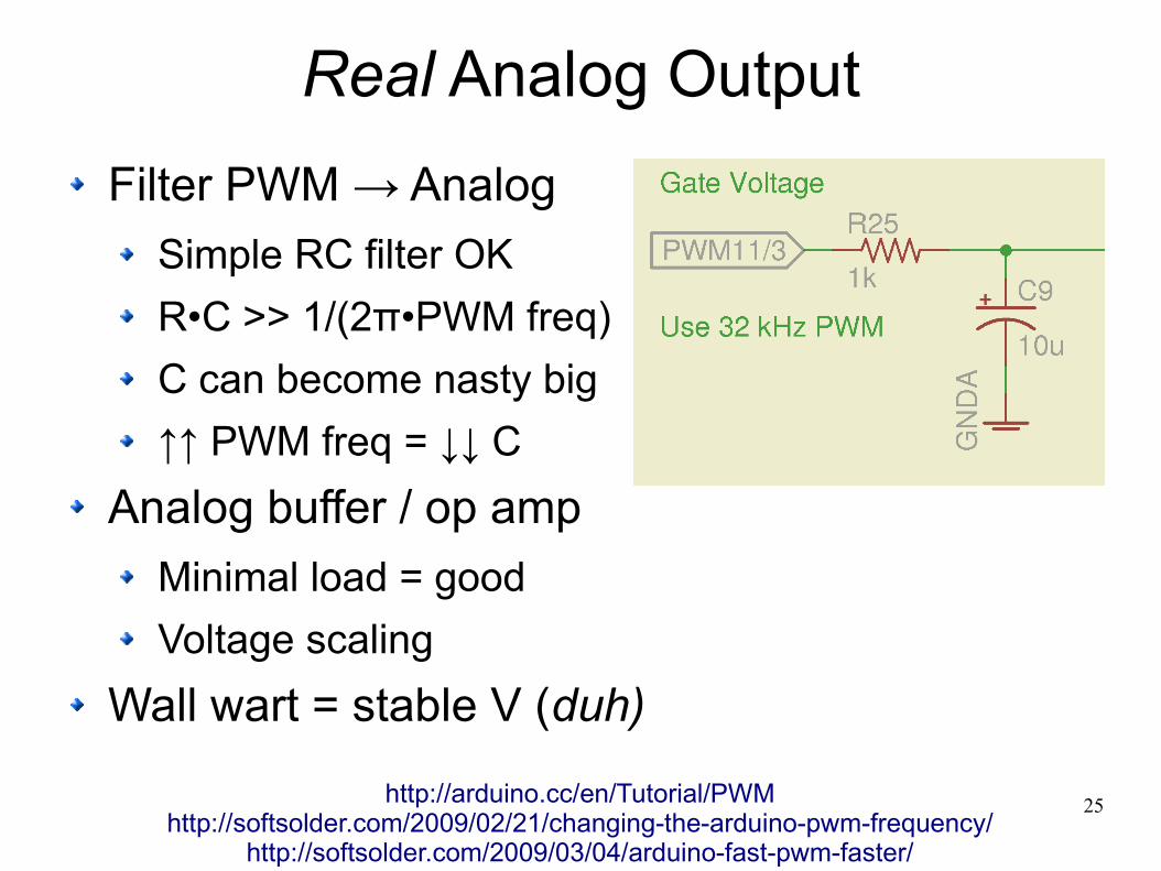
25
Real Analog Output
Filter PWM → Analog
Simple RC filter OK
R•C >> 1/(2π•PWM freq)
C can become nasty big
↑↑ PWM freq = ↓↓ C
Analog buffer / op amp
Minimal load = good
Voltage scaling
Wall wart = stable V (duh)
http://arduino.cc/en/Tutorial/PWMhttp://softsolder.com/2009/02/21/changing-the-arduino-pwm-frequency/
http://softsolder.com/2009/03/04/arduino-fast-pwm-faster/

26
Analog Input
analogRead(A0)
Minimum 0 = 0V
Maximum 1023 = “5V” (pretty close)
Depends on actual supply voltage!Value = 1023 * (V / AREF)
Wall wart = stable AREF = (duh)
0 V ≤ [Analog voltage] ≤ 5 V
Avoid digital pin output before AI
Average several AI readings?
http://arduino.cc/en/Tutorial/AnalogInputPinshttp://arduino.cc/en/Reference/AnalogReference

27
Single LED
Assume 20 mA max
Continuous, not peak
10 mA = bright enough
Do you know different?
Forward voltage drop
Red - orange = 2 V
Yellow - green = 2.5 V
Blue & white = 3.5 V
Arduino = one LED / pin
Pin = 5 V & 20 mA maximum
https://en.wikipedia.org/wiki/LED_circuit

28
LED Forward Voltage vs. Color
http://softsolder.com/2013/04/02/led-forward-voltages-vs-color/

29
Single LED Resistor
Resistor limits LED current
This is not optional!
Ohm’s Law for resistor: R = VR / I
Want current I = 10 mA (< 20 mA, OK?)Same as LED because they’re in series
Voltage = VCC
– VLED
= “5V” – 1.8 V = 3.2 V
VLED
varies with color, so be careful!
Resistance = R = V / I = 3.2 / 0.01 = 320 Ω
Round up to next standard value = 330 Ω
Measure actual VR to verify: I = V
R / R

30
Lab: Measure LED Voltage
LED
Pick a color
Use R = 270 Ω? (compute current)
Program
pinMode(11,OUTPUT)
digitalWrite(11,HIGH)
Print analogRead(A0)
Compute actual voltage
Bonus
Compute LED current
Compute LED power
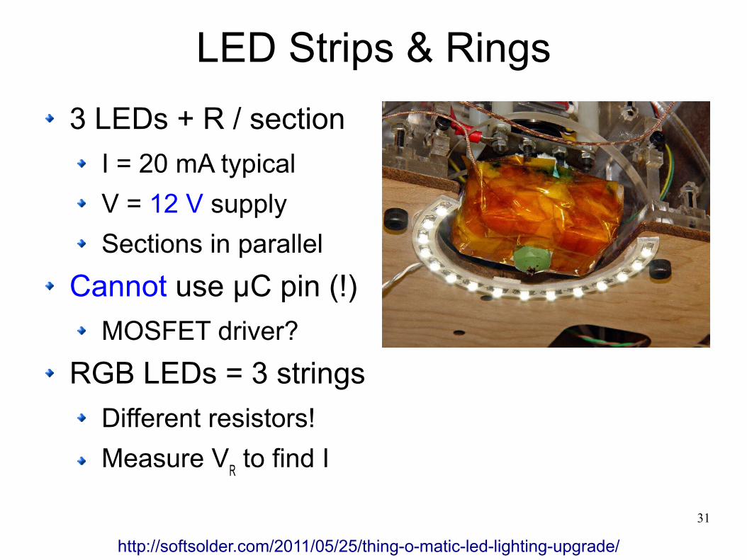
31
LED Strips & Rings
3 LEDs + R / section
I = 20 mA typical
V = 12 V supply
Sections in parallel
Cannot use μC pin (!)
MOSFET driver?
RGB LEDs = 3 strings
Different resistors!
Measure VR to find I
http://softsolder.com/2011/05/25/thing-o-matic-led-lighting-upgrade/
32
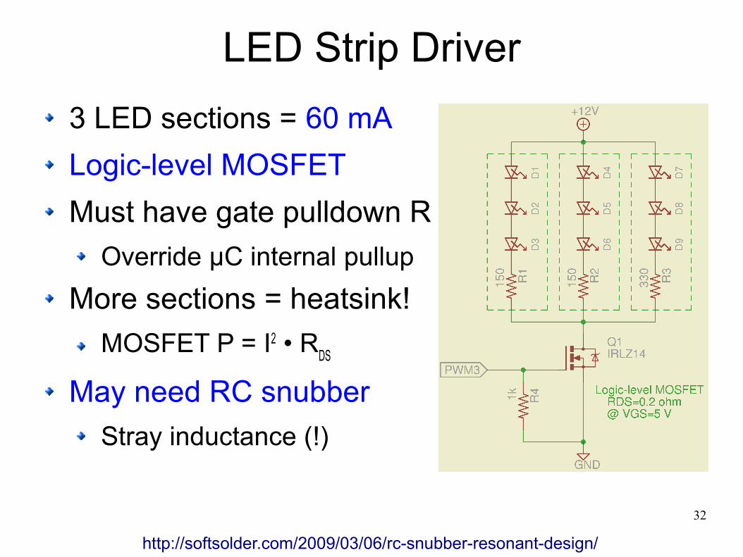
LED Strip Driver
3 LED sections = 60 mA
Logic-level MOSFET
Must have gate pulldown R
Override μC internal pullup
More sections = heatsink!
MOSFET P = I2 • RDS
May need RC snubber
Stray inductance (!)
http://softsolder.com/2009/03/06/rc-snubber-resonant-design/
33
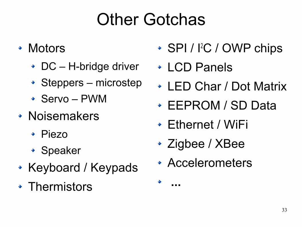
Other Gotchas
Motors
DC – H-bridge driver
Steppers – microstep
Servo – PWM
Noisemakers
Piezo
Speaker
Keyboard / Keypads
Thermistors
SPI / I2C / OWP chips
LCD Panels
LED Char / Dot Matrix
EEPROM / SD Data
Ethernet / WiFi
Zigbee / XBee
Accelerometers
...

34
Everything Else
Is
A Simple Matter of Software

35
arduino.cc/en/Reference/HomePagewww.ladyada.net/learn/arduino/index.html
todbot.com/blog/spookyarduino/www.sparkfun.com/tutorials
and, of course ...softsolder.com/tag/arduino/
More Info

36
Some web images probably copyrighted, butshown & attributed here under “fair use”
[whatever that is]
The rest is my own work
●
This work is licensed under theCreative Commons Attribution-Noncommercial-Share Alike 3.0 United States License.
To view a copy of this license, visithttp://creativecommons.org/licenses/by-nc-sa/3.0/us/
or send a letter toCreative Commons, 543 Howard Street, 5th Floor
San Francisco, California, 94105, USA.
Copyright-ish Stuff

37
Ed Nisley
September 1962
Say “NISS-lee”, although we're on the half-essed branch of the tree
Engineer (ex PE), Hardware Hacker, Programmer, Author
The Embedded PC's ISA Bus: Firmware, Gadgets, Practical Tricks Circuit Cellar www.circuitcellar.com Firmware Furnace (1988-1996) - Nasty, grubby hardware bashing Above the Ground Plane (2001 ...) - Analog and RF stuff
Digital Machinist www.homeshopmachinist.net Along the G-Code Way (2008 ...) - G-Code, math, 3D printing
Dr. Dobb’s Journal www.ddj.com Embedded Space (2001-2006) - All things embedded Nisley’s Notebook (2006-2007) - Hardware & software collisions
My Blog: The Smell of Molten Projects in the Morningsoftsolder.com

38
If youcan’t read this
thenmake a new friend
‘way up front