Arduino Online Tutorials - EP Software
52
EP SOFTWARE Arduino Basics | TUTORIAL by EP Software | © 2019 | Page 1 of 52
Transcript of Arduino Online Tutorials - EP Software
EP SOFTWARE
Arduino Basics | TUTORIAL by EP Software | © 2019 | Page 1 of 52
EP SOFTWARE
Arduino Basics | TUTORIAL by EP Software | © 2019 | Page 2 of 52
Content.
1 Introduction ........................................................................................................ 3
2 Set up the software and open a new sketch ......................................................... 4
3 Let the Arduino speak to your computer .............................................................. 6
4 Build your first circuit .......................................................................................... 8
5 LED on! – Variable types .................................................................................... 10
6 LED on-off-loop ................................................................................................. 12
7 if-then-else ........................................................................................................ 13
8 Button circuit ..................................................................................................... 15
9 Press button -> LED on ...................................................................................... 16
10 LED switch ....................................................................................................... 18
11 switch-case function ........................................................................................ 19
12 First own function ........................................................................................... 20
13 Traffic light circuit ........................................................................................... 22
14 Traffic light ..................................................................................................... 23
15 Dimmer ........................................................................................................... 25
16 For-loop .......................................................................................................... 26
17 LED increase/decrease ..................................................................................... 27
18 Traffic light with dimmer function ................................................................... 28
19 RGB circuit ....................................................................................................... 30
20 LED back and forth .......................................................................................... 31
21 While-loop ....................................................................................................... 35
22 Chaser with while-loop .................................................................................... 36
23 Chaser with while-loop and dimmer ................................................................. 38
24 Police flashlight ............................................................................................... 41
Final codes ............................................................................................................ 42
“Let your Arduino speak to your computer” ........................................................ 43
“LED on! – Variable types” ................................................................................... 43
“LED on-off-loop” ................................................................................................ 44
“Press button -> LED on” ..................................................................................... 44
“LED switch” ....................................................................................................... 45
“switch-case function” ........................................................................................ 45
“Traffic light” ...................................................................................................... 46
“Dimmer” ........................................................................................................... 46
“LED increase/decrease” ..................................................................................... 47
“Traffic light with dimmer” ................................................................................. 47
“LED back and forth” .......................................................................................... 48
“Chaser with while-loop” ..................................................................................... 49
“Chaser with while-loop and dimmer” ................................................................. 50
“Police flashlight” ............................................................................................... 51
References ............................................................................................................ 52
Images: .............................................................................................................. 52
Code: ................................................................................................................. 52
EP SOFTWARE
Arduino Basics | TUTORIAL by EP Software | © 2019 | Page 3 of 52
1 Introduction
Welcome to the EP Software Arduino Basics Online Tutorial!
In this tutorial, you will learn the basics for programming an Arduino and simple
programming skills useful for all programming languages such as C, Java and more.
In the coming twenty-four-step tutorial, we will start with easy programming steps
and in the end, you will have made some small but wonderful Arduino projects. The
skills you will learn are good for continuing furthermore.
For a start, you need some Arduino gadgets. You will find the following gadgets on
Amazon or other resellers:
- Red-, Blue-, Green-LED
- Three 220-Ohm Resistors
- One 10k-Ohm Resistor
- Button
- Cables
- Arduino (or other) UNO
- Breadboard
You can buy every single item or all together in a bundle. For example, “FREENOVE
Super Arduino Starter Kit” (link) includes all needed items, only for 19,95 € on
Amazon.
Also, for programming, you will need the “Arduino IDE” software. Download the
“Arduino IDE” here. Do not worry this software is free!
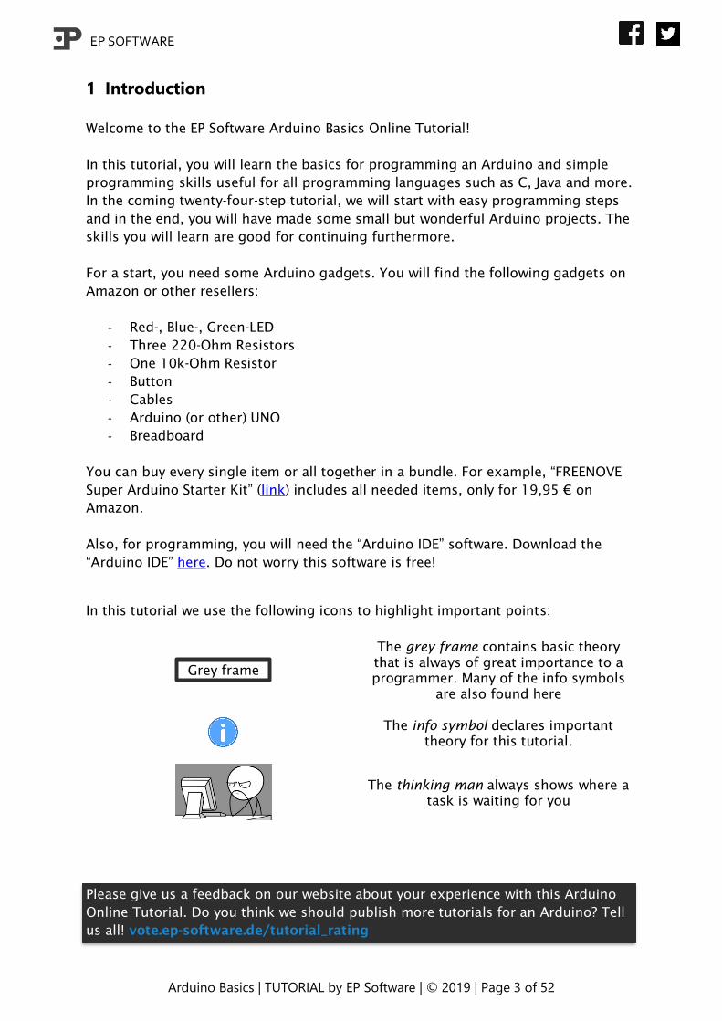
In this tutorial we use the following icons to highlight important points:
Grey frame
The grey frame contains basic theory
that is always of great importance to a
programmer. Many of the info symbols
are also found here
The info symbol declares important
theory for this tutorial.
The thinking man always shows where a
task is waiting for you
Please give us a feedback on our website about your experience with this Arduino
Online Tutorial. Do you think we should publish more tutorials for an Arduino? Tell
us all! vote.ep-software.de/tutorial_rating
EP SOFTWARE
Arduino Basics | TUTORIAL by EP Software | © 2019 | Page 4 of 52
2 Set up the software and open a new sketch
First of all, the software setup:
1. Connect your Arduino with your Computer
2. Start “Arduino IDE”
3. Go to “Tools” -> “Board” -> and select your Arduino Board, in our example
“Arduino/Genuino UNO”
4. Go to “Tools” -> “Port” -> and select the Port, for example “COM6
(Arduino/Genuino UNO)”
5. Now the Arduino IDE knows how to find your Arduino
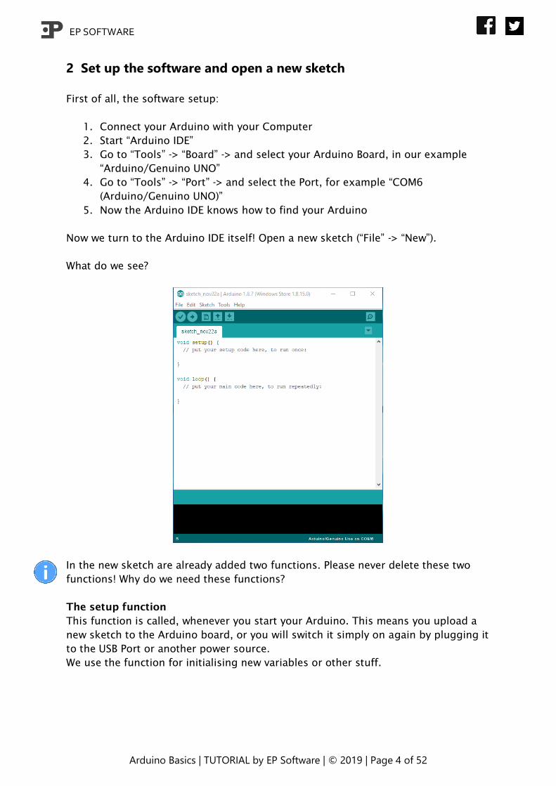
Now we turn to the Arduino IDE itself! Open a new sketch (“File” -> “New”).
What do we see?
In the new sketch are already added two functions. Please never delete these two
functions! Why do we need these functions?
The setup function
This function is called, whenever you start your Arduino. This means you upload a
new sketch to the Arduino board, or you will switch it simply on again by plugging it
to the USB Port or another power source.
We use the function for initialising new variables or other stuff.

EP SOFTWARE
Arduino Basics | TUTORIAL by EP Software | © 2019 | Page 5 of 52
The loop function
This function will repeat all code as fast as possible, which is in this function. It is
working like a repeater. We will use this function for running simply everything.
In sum, these both functions are starting and running our code and Arduino.
EP SOFTWARE
Arduino Basics | TUTORIAL by EP Software | © 2019 | Page 6 of 52
3 Let the Arduino speak to your computer
Start the Arduino IDE, open a new sketch and connect the Arduino to your
computer.
We will use now the “Serial Monitor”. The serial monitor will show the answers from
our Arduino on our computer. We will use it to check, if our programme is doing
right, later on. The Arduino needs to know how to reach the monitor compared to
our daily lives, where we need to know what the recipient's address is.
We will give the Arduino this information in the setup function, which you learned
about in the last chapter.
First code! We write in the setup function following code:
This information says: Start the serial monitor with the address “9600”.
After initialising the serial monitor, we will send a message that our programme has
started. We continue in the setup function:
“println()” means we are printing the following text “---Programme started---“ in a
new line. If you want to print several information in one row, you can write
“.print(#text#);”.
You may have recognized that after every statement we are writing a semicolon (“;”).
The software needs this symbol to know, where a statement is finished. This is
equal to a point at the end of a sentence.
Now it is time to start our programme. First, we are starting the serial monitor. Go
to “Tools” -> “Serial monitor”. A new window will appear. Check if in the low right
corner, in the drop-down menu, “9600 baud” is selected.
Now we are uploading the code to the Arduino. Click on the right arrow button ( )
in the left upper corner. The software will now check our code, if any errors have
been made, afterwards the code will be uploaded. Our Arduino will show us, with a
small light show, that the code has been uploaded.
If you have problems with coding, you will find at the end of this document all
solutions for any chapter/step in this tutorial, or click on the link at the end of each
chapter/step.
EP SOFTWARE
Arduino Basics | TUTORIAL by EP Software | © 2019 | Page 7 of 52
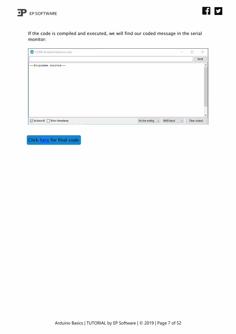
If the code is compiled and executed, we will find our coded message in the serial
monitor:
Click here for final code

EP SOFTWARE
Arduino Basics | TUTORIAL by EP Software | © 2019 | Page 8 of 52
4 Build your first circuit
We will build in this chapter our first Arduino circuit, which we will use afterwards…
Take your breadboard, 220-Ohm resistor two cables and the red LED. Follow the
instructions below:
Each slot in the breadboard is for one
pin of a cable, LED or resistor. In every
row the columns (Terminal Strips) a, b,
c, d, e and f, g, h, i, j are connected, so
if you apply voltage to one of these
slots, all other four pins will have this
voltage. The Divider splits the Terminal
Strips from each other. Otherwise are
the + and – column (Power rails) not
connected horizontal (row), but vertical
(column). If you will apply voltage to
one of their slots, all pins in the column
will have this voltage.
We will use the + and – column for
feeding all components with voltage.
EP SOFTWARE
Arduino Basics | TUTORIAL by EP Software | © 2019 | Page 9 of 52
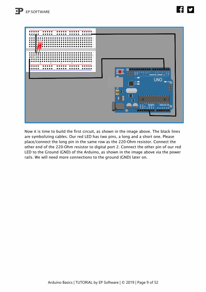
Now it is time to build the first circuit, as shown in the image above. The black lines
are symbolizing cables. Our red LED has two pins, a long and a short one. Please
place/connect the long pin in the same row as the 220-Ohm resistor. Connect the
other end of the 220-Ohm resistor to digital port 2. Connect the other pin of our red
LED to the Ground (GND) of the Arduino, as shown in the image above via the power
rails. We will need more connections to the ground (GND) later on.
EP SOFTWARE
Arduino Basics | TUTORIAL by EP Software | © 2019 | Page 10 of 52
5 LED on! – Variable types
As we finished to build the small circuit, we program the corresponding programme.
We learnt before, that our Arduino does not know much about its ports (pins). So,
we have to teach it, which port is connected to what. First, we setup all information
about the port. If the port is sending or receiving data. We use following code:
pinMode(pin number, type (OUTPUT/INPUT);
Open a new sketch. Add this line of code to the setup function of the new sketch.
Now our Arduino knows that pin (port) number “redLED” is a pin where a current/
message leaves our Arduino. If the pin takes the role as a receiver, we will write
“INPUT” instead of “OUTPUT”. If we would compile the code with just this line of
code, our Arduino software will spit an error. Because the Arduino does not know
what “redLED” is. We must define the variable “redLED” before starting. The variable
“redLED” is an integer (number). We will write following code before our setup
function:
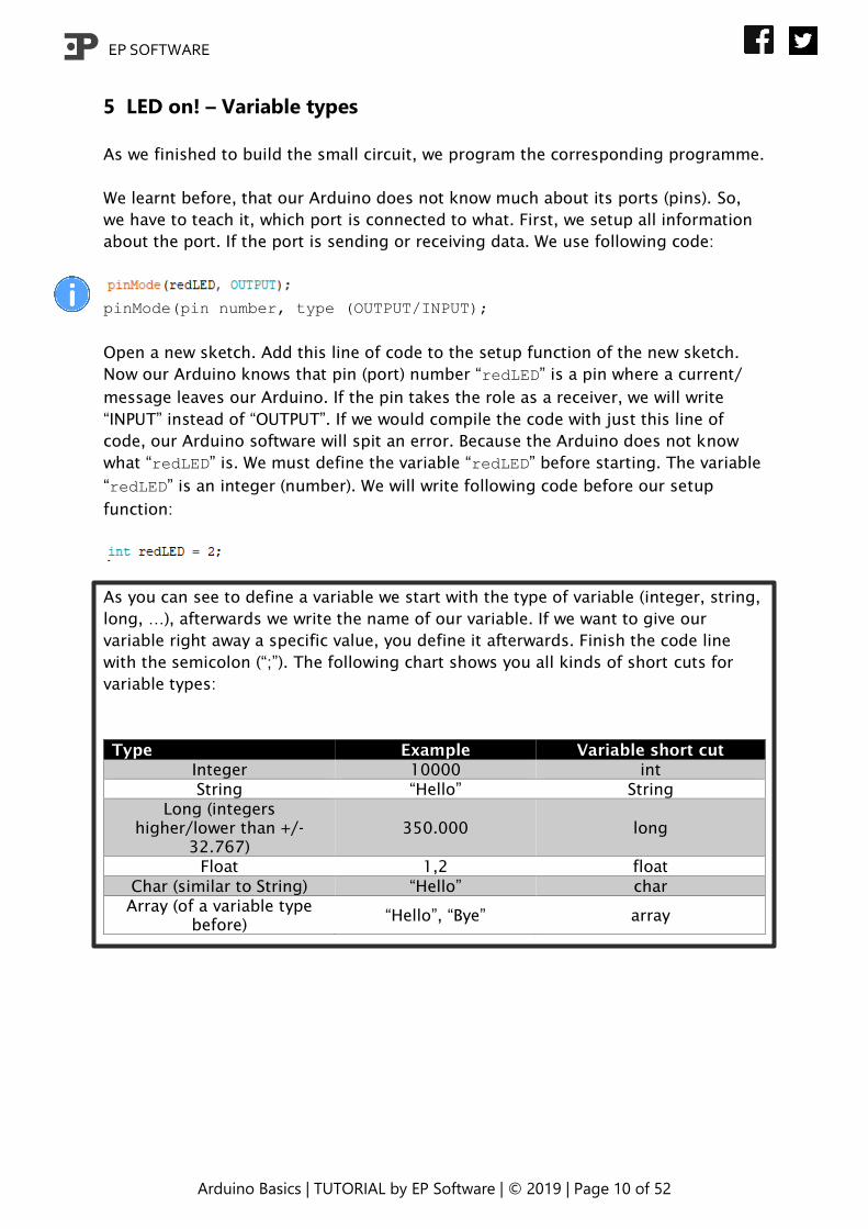
As you can see to define a variable we start with the type of variable (integer, string,
long, …), afterwards we write the name of our variable. If we want to give our
variable right away a specific value, you define it afterwards. Finish the code line
with the semicolon (“;”). The following chart shows you all kinds of short cuts for
variable types:
Type Example Variable short cut
Integer 10000 int
String “Hello” String
Long (integers
higher/lower than +/-
32.767)
350.000 long
Float 1,2 float
Char (similar to String) “Hello” char
Array (of a variable type
before) “Hello”, “Bye” array

EP SOFTWARE
Arduino Basics | TUTORIAL by EP Software | © 2019 | Page 11 of 52
The code so far:
The last missing bit of our code for turning the LED on and off is coming right now.
After setting the pin mode, we want to turn on the LED. Because we are using the
digital Pin number two, we will write following code in the setup function:
digitalWrite(number of pin, state: HIGH/LOW);
The digitalWrite() function needs two information. The pin number (redLED) and
which state should be sent. There are two states: “HIGH” (maximum current) and
“LOW” (no current), or in another way: power (in our case LED) on/off.
Click here for final code
After adding the last line of code, we can compile and run our new code. Do not
forget to plug your Arduino to your computer. If you have any problems with
uploading the code to your Arduino, check if Port and Board are set right in the
“Tools” menu.
EP SOFTWARE
Arduino Basics | TUTORIAL by EP Software | © 2019 | Page 12 of 52
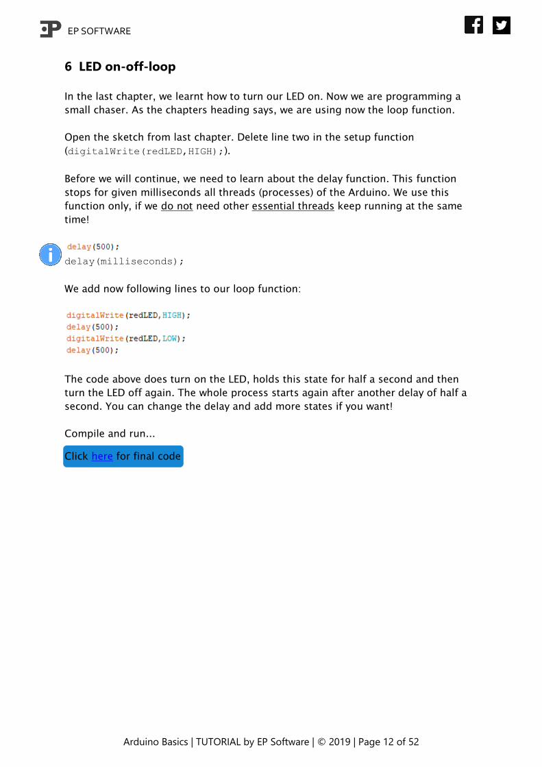
6 LED on-off-loop
In the last chapter, we learnt how to turn our LED on. Now we are programming a
small chaser. As the chapters heading says, we are using now the loop function.
Open the sketch from last chapter. Delete line two in the setup function
(digitalWrite(redLED,HIGH);).
Before we will continue, we need to learn about the delay function. This function
stops for given milliseconds all threads (processes) of the Arduino. We use this
function only, if we do not need other essential threads keep running at the same
time!
delay(milliseconds);
We add now following lines to our loop function:
The code above does turn on the LED, holds this state for half a second and then
turn the LED off again. The whole process starts again after another delay of half a
second. You can change the delay and add more states if you want!
Compile and run...
Click here for final code
EP SOFTWARE
Arduino Basics | TUTORIAL by EP Software | © 2019 | Page 13 of 52
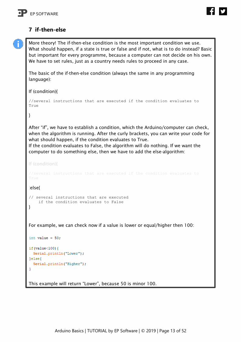
7 if-then-else
More theory! The if-then-else condition is the most important condition we use.
What should happen, if a state is true or false and if not, what is to do instead? Basic
but important for every programme, because a computer can not decide on his own.
We have to set rules, just as a country needs rules to proceed in any case.
The basic of the if-then-else condition (always the same in any programming
language):
If (condition){
//several instructions that are executed if the condition evaluates to
True
}
After “if”, we have to establish a condition, which the Arduino/computer can check,
when the algorithm is running. After the curly brackets, you can write your code for
what should happen, if the condition evaluates to True.
If the condition evaluates to False, the algorithm will do nothing. If we want the
computer to do something else, then we have to add the else-algorithm:
If (condition){
//several instructions that are executed if the condition evaluates to
True
}else{
// several instructions that are executed
if the condition evaluates to False
}
For example, we can check now if a value is lower or equal/higher then 100:
This example will return “Lower”, because 50 is minor 100.
EP SOFTWARE
Arduino Basics | TUTORIAL by EP Software | © 2019 | Page 14 of 52
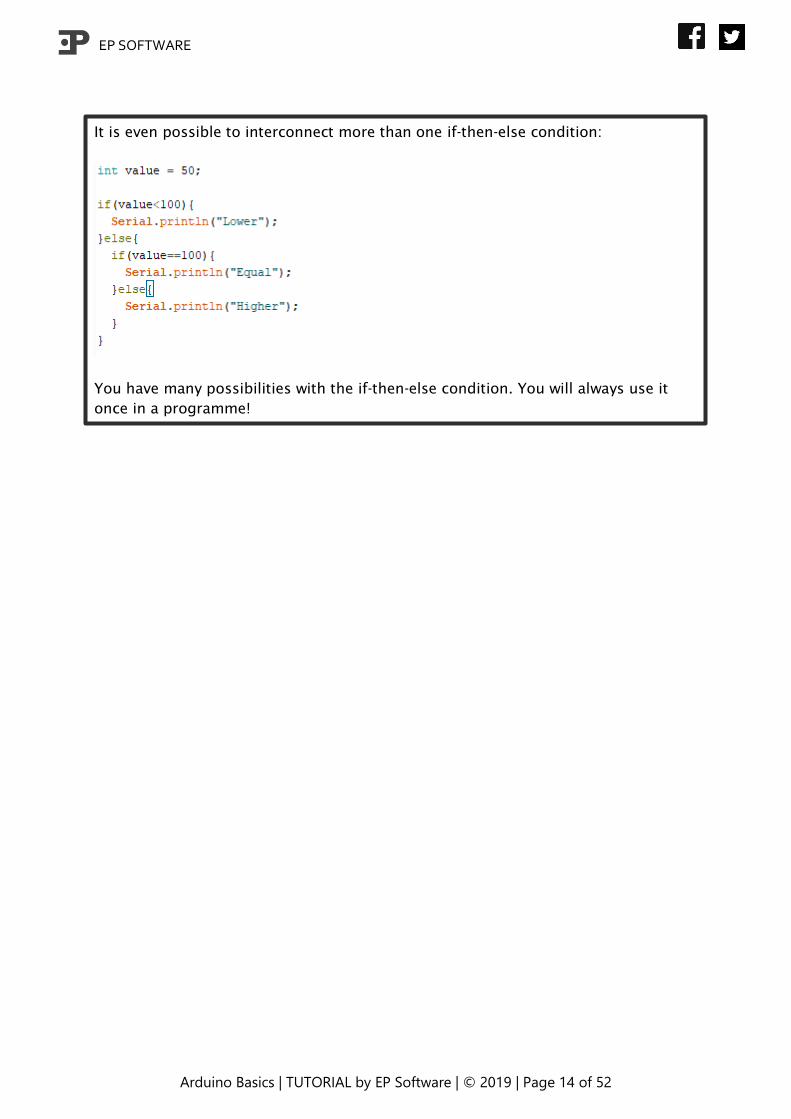
It is even possible to interconnect more than one if-then-else condition:
You have many possibilities with the if-then-else condition. You will always use it
once in a programme!
EP SOFTWARE
Arduino Basics | TUTORIAL by EP Software | © 2019 | Page 15 of 52
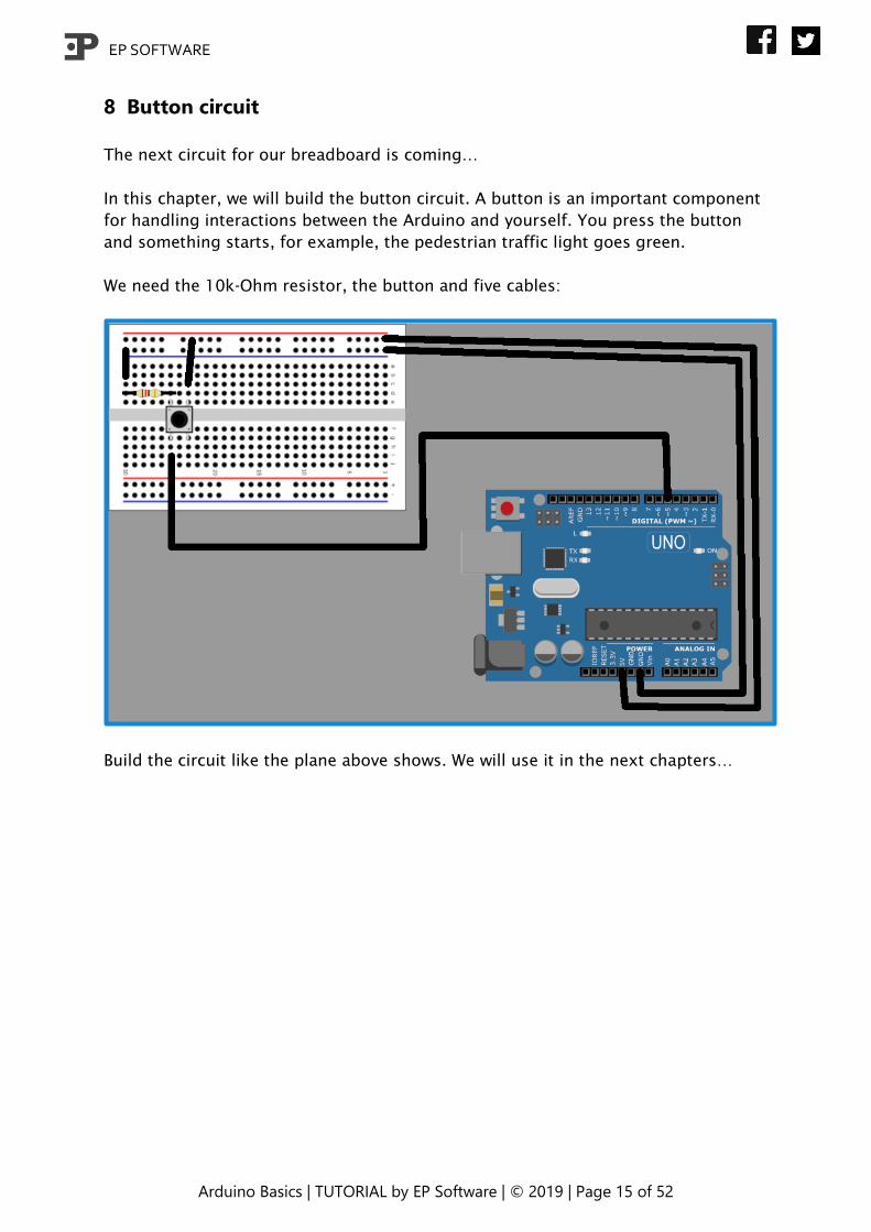
8 Button circuit
The next circuit for our breadboard is coming…
In this chapter, we will build the button circuit. A button is an important component
for handling interactions between the Arduino and yourself. You press the button
and something starts, for example, the pedestrian traffic light goes green.
We need the 10k-Ohm resistor, the button and five cables:
Build the circuit like the plane above shows. We will use it in the next chapters…
EP SOFTWARE
Arduino Basics | TUTORIAL by EP Software | © 2019 | Page 16 of 52
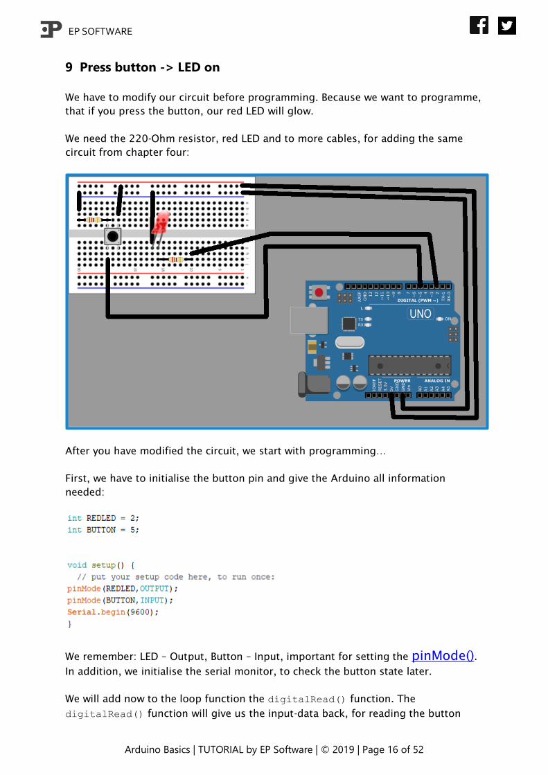
9 Press button -> LED on
We have to modify our circuit before programming. Because we want to programme,
that if you press the button, our red LED will glow.
We need the 220-Ohm resistor, red LED and to more cables, for adding the same
circuit from chapter four:
After you have modified the circuit, we start with programming…
First, we have to initialise the button pin and give the Arduino all information
needed:
We remember: LED – Output, Button – Input, important for setting the pinMode().
In addition, we initialise the serial monitor, to check the button state later.
We will add now to the loop function the digitalRead() function. The
digitalRead() function will give us the input-data back, for reading the button
EP SOFTWARE
Arduino Basics | TUTORIAL by EP Software | © 2019 | Page 17 of 52
state. We also need a variable to save the receiving button state. Because the button
just can have to button states (pressed/not pressed), we can use a Boolean variable.
A Boolean can only have to states true or false, just as the button has.
We add the following line above the setup function:
And following line to the loop function:
Now, we get the button state. We need to use this information! We learnt already
something about the if-then-else condition. We will use this condition now to set
what our Arduino should do if the button is pressed. Good to now: if the button is
pressed the digitalRead() function sends us “true” back.
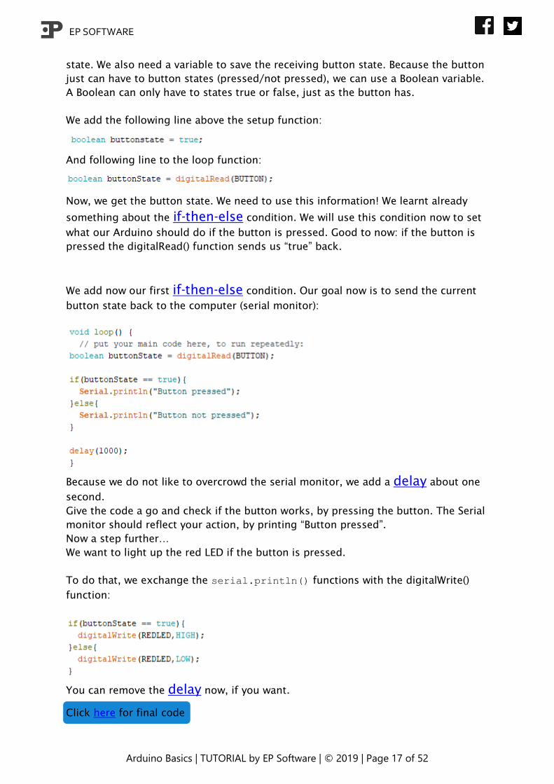
We add now our first if-then-else condition. Our goal now is to send the current
button state back to the computer (serial monitor):
Because we do not like to overcrowd the serial monitor, we add a delay about one
second.
Give the code a go and check if the button works, by pressing the button. The Serial
monitor should reflect your action, by printing “Button pressed”.
Now a step further…
We want to light up the red LED if the button is pressed.
To do that, we exchange the serial.println() functions with the digitalWrite()
function:
You can remove the delay now, if you want.
Click here for final code
EP SOFTWARE
Arduino Basics | TUTORIAL by EP Software | © 2019 | Page 18 of 52
10 LED switch
Last chapter, we have created an algorithm to switch on our red LED as long we
pressed the button. This chapter, we will modify this algorithm to turn our button to
a real light switch.
The only thing what will change is that we have to save in which state our LED is
(on/off) and the buttonState condition is no longer responsible for turning the LED
on or off.
First, we add a new variable. The new variable is, as the buttonState variable, a
Boolean. Please add following line to the variable setup in the beginning of the
programme:
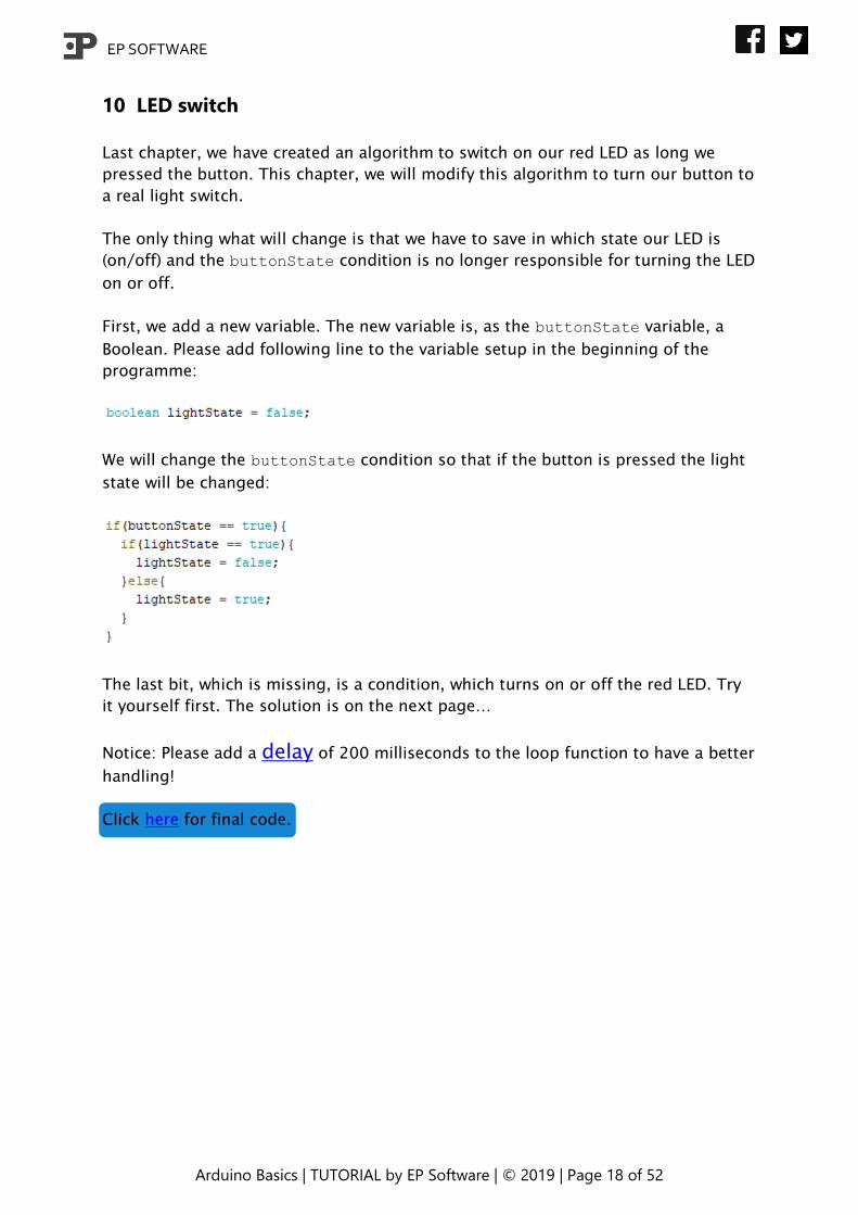
We will change the buttonState condition so that if the button is pressed the light
state will be changed:
The last bit, which is missing, is a condition, which turns on or off the red LED. Try
it yourself first. The solution is on the next page…
Notice: Please add a delay of 200 milliseconds to the loop function to have a better
handling!
Click here for final code.
EP SOFTWARE
Arduino Basics | TUTORIAL by EP Software | © 2019 | Page 19 of 52
11 switch-case function
The switch-case function makes it much easy and tidier for us to check, if some
value is called and to process it.
The switch-case function has an easy structure:
switch(variable) {
case value: //something happens
break;
case other value: //something different happens
break;
}
The switch()-statement is the beginning and calls the variable whose value should be
compared with various values. Each comparison starts with “case”. Afterwards you
write the value (only integer or string/char is allowed to use) and then a colon. Now
you can add all statements, which should be done if the variable is equal to the
value. If you end the statements for one case, you finish it with “break;” which stops
the switch function.
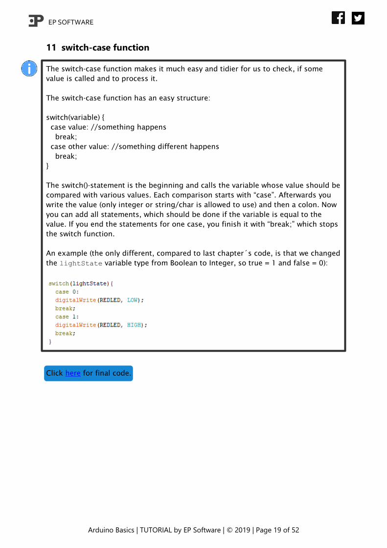
An example (the only different, compared to last chapter´s code, is that we changed
the lightState variable type from Boolean to Integer, so true = 1 and false = 0):
Click here for final code.

EP SOFTWARE
Arduino Basics | TUTORIAL by EP Software | © 2019 | Page 20 of 52
12 First own function
We want to teach you how to
programme an Arduino and we
want to show you basics
programming skills, then we do
not come around to show you
the best way of keeping your
programme tidy!
A good programmer does not
write all statements (functions)
down in a long list. He
outsources all statements
(function) separately in their
own functions. For example,
we outsource all conditions
from our loop function, from
last chapter´s code (Screenshot
on the left).
Structure of a function without
any return value:
void [Name]([Variable type]
[Name of the variable]){
//statements
}
Structure of a function with a
return value:
int [Name]([Variable type]
[Name of the variable]){
int value = 0;
//statements
return value;
}
The declaration of a new function starts with "void", if the function should return a
value, write down the type of a variable. This is followed by the name of the
function, such as "LightOnOff". Afterwards between the brackets you can define
variables which, when executed, can be passed to the function and used in the
function. If you want to return a value, terminate the function with return [value /
variable]. This statement terminates the function, all lines after that are not
executed!

EP SOFTWARE
Arduino Basics | TUTORIAL by EP Software | © 2019 | Page 21 of 52
In the future, we will write all algorithm in separate functions, which will be
executed from other functions. To execute a function, you will write the Name, such
as “LightOnOff” and behind it brackets. If the function needs parameters given
along, add them to the brackets, for example: LightOnOff(lightState).
Update your code as shown on the page before.
EP SOFTWARE
Arduino Basics | TUTORIAL by EP Software | © 2019 | Page 22 of 52
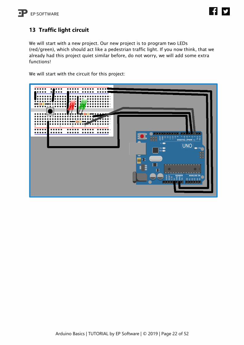
13 Traffic light circuit
We will start with a new project. Our new project is to program two LEDs
(red/green), which should act like a pedestrian traffic light. If you now think, that we
already had this project quiet similar before, do not worry, we will add some extra
functions!
We will start with the circuit for this project:
EP SOFTWARE
Arduino Basics | TUTORIAL by EP Software | © 2019 | Page 23 of 52
14 Traffic light
First, try to programme a traffic light with the knowledge obtained so far, which at
the push of a button changes from red to green and the other way around. Do not
continue to the next page, if you want to try it!
A hint for all who like to try, but do not know further:
We need if-then-else conditions, digitalWrite() and digitalRead(). In the best
way, you build it up with self-made functions.
You have no clue? Try to use the if-then-else condition to check the button and
traffic light (if it is red or green) state.
If you have succeeded, tried it, or just skipped the task, we are now programming
the traffic light together…
EP SOFTWARE
Arduino Basics | TUTORIAL by EP Software | © 2019 | Page 24 of 52
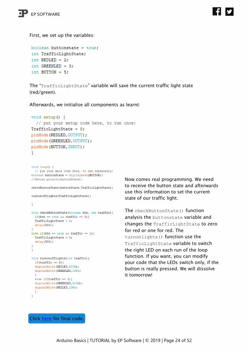
First, we set up the variables:
The “TrafficLightState” variable will save the current traffic light state
(red/green).
Afterwards, we initialise all components as learnt:
Now comes real programming. We need
to receive the button state and afterwards
use this information to set the current
state of our traffic light.
The checkButtonState() function
analysis the buttonstate variable and
changes the TrafficLightState to zero
for red or one for red. The
turnonlights() function use the
TrafficLightState variable to switch
the right LED on each run of the loop
function. If you want, you can modify
your code that the LEDs switch only, if the
button is really pressed. We will dissolve
it tomorrow!
Click here for final code.
EP SOFTWARE
Arduino Basics | TUTORIAL by EP Software | © 2019 | Page 25 of 52
15 Dimmer
We will change the circuit a little bit, because not all pins are capable of dimming
LEDs. Please change the pin number two (red LED) to nine and three (green LED) to
ten.
Please open a new sketch, because we will use the dimmer function in the coming
chapters for our traffic light, but in this chapter, we just dim one LED.
Luckily, it is not very difficult to dim a LED. We need to learn only two things. First,
only digital pins of our Arduino with this symbol are capable of releasing different
currents. And the second thing is, that we have to use now the analogWrite()
function, because the digitalWrite() function only can send HIGH or LOW signals.
analogWrite(PIN, Value);
The analogWrite() function is similar to the digitalWrite() function. First you
claim the pin and then the value of the current (in range of 0-255, but only integer
numbers). You also can use HIGH (=255) or LOW (=0). For example, I want to dim
the red LED by 50%, then I write: analogWrite(REDLED, 127).
Please try on your own to dim the red and green LED to 75%, 50% and 25%.
Use our general construction: Setup variables, initialise variables and outsource
functions.
Click here for final code
(do not worry if your code works, but looks different, there are many ways!).

EP SOFTWARE
Arduino Basics | TUTORIAL by EP Software | © 2019 | Page 26 of 52
16 For-loop
Some more theory, but it is important to learn all about basic algorithms you will
always need in programming. The for-loop algorithm is needed to repeatedly
repeat processes with other values. For example, to check a list point by point to a
specific value.
The structure of the function:
for (initialization; condition; increment) {
//statement(s);
}
Example increasing LED brightness:
for(int i = 0; i <= 255; i++){
analogWrite(REDLED, i);
}
In the example, we increase the control variable i, and set the variable as the red
LED current (brightness).
So, you can use to increase or decrease a value and use every value in an algorithm.
You also can start other functions out of the for-loop. There are many ways to use
this loop!

EP SOFTWARE
Arduino Basics | TUTORIAL by EP Software | © 2019 | Page 27 of 52
17 LED increase/decrease
Have a try and create a project with the given information from last chapter, which
will increase and decrease the red LED brightness every 10 milliseconds.
Hint: Use the if-then-else condition to check if the red LED is on LOW (=0) or HIGH
(=255). For the increasing/decreasing, use the for-loop. Use a control variable to
know in every moment, if the LED is LOW or HIGH. Do not forget about outsourcing!
Click here for final code.
EP SOFTWARE
Arduino Basics | TUTORIAL by EP Software | © 2019 | Page 28 of 52
18 Traffic light with dimmer function
In this chapter, we will modify our traffic light sketch. We have learnt the last days
how to change the brightness of our LEDs and how to use the for-loop. In real life,
older traffic lights are changing colour with a dimming effect, because the old light
bulb does not turn off immediate, like a LED.
First, we open up the sketch from chapter 14. Do not forget to switch the pin
numbers of the red and green Led from 2/3 to 9/10! Now we locate where we have
to change or add something, for dimming off the current LED and dimming on the
other one at the same time.
For doing that we have to implement some new functions. We cannot use the
turnonofflights(int traffic) function, because this function just can decide
whether the red or green Led is on. The dimming function must be called earlier in
the checkButtonState(boolean btn, int traffic) function.
If the button is pressed we have to make sure that the turnonofflights(int
traffic) function do not change the colour immediately. Following steps have to
be done before the turnonofflights(int traffic) function operating:
Button pressed -> start dimming and colour change -> TrafficLightState = 0/1 ->
continue as known…
If you want, you can have a try first, but there is no shame, if you follow our tutorial
immediately…

EP SOFTWARE
Arduino Basics | TUTORIAL by EP Software | © 2019 | Page 29 of 52
We are starting with creating to new functions, which are changing the colours with
the dimming effect. One for red to green and one for green to red:
The for-loop is increasing the brightness of upcoming colour and decreasing the
old colour in the same speed. The delay of one millisecond is needed, because
otherwise it will happen to fast in just milliseconds. With the small delay it takes a
quarter of a second, slow enough for our eyes.
Afterwards we implement these two functions in the checkbuttonstate(boolean
btn, int traffic) function:
We have to add the functions before the turnonofflights(int traffic) function
is called, because otherwise the LED is immediately on without dimming. Try to
optimise the dimming further on your own!
Click here for final code.

EP SOFTWARE
Arduino Basics | TUTORIAL by EP Software | © 2019 | Page 30 of 52
19 RGB circuit
Last change for our breadboard. We will extend our circuit with another LED. Add
the blue LED as shown below. We need another 220-Ohm resistor, two cables and
the blue LED.
EP SOFTWARE
Arduino Basics | TUTORIAL by EP Software | © 2019 | Page 31 of 52
20 LED back and forth
This task will be easy, because we use all knowledge, we learnt so far. Your task is
to program a chaser with our three LEDs: Red-Green-Blue-Green-Red each time the
button becomes pressed. Sounds easy, right?
For all of you, who feel still not comfortable, we will guide you through. If you are
interested in learning instead of copying, we recommend starting first on your own
and afterwards having a look to the following code! If you need help during trying,
each part of this chapter´s task is a separated part:
Button state
LED on/off
Chaser
Finish
We will improve the chaser in the coming chapters. Therefore, we need the basis we
are about to programme chapter.
EP SOFTWARE
Arduino Basics | TUTORIAL by EP Software | © 2019 | Page 32 of 52
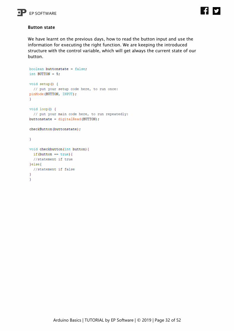
Button state
We have learnt on the previous days, how to read the button input and use the
information for executing the right function. We are keeping the introduced
structure with the control variable, which will get always the current state of our
button.

EP SOFTWARE
Arduino Basics | TUTORIAL by EP Software | © 2019 | Page 33 of 52
LED on/off
Please do not forget about outsourcing and the “switch and case”-function! We
have learnt the basic way, how to turn on a LED, but we have continued with
outsourcing and improving this simple function. In this chapter, we write a function,
which turns on the right LED, if it is called with an ID (integer value). Do not forget
to turn off all other LED, which are not wanted to stay on.
We have added also the delay-function, because we need to halt the programme
after each colour change, otherwise we would not see a thing. The Arduino simply
works to fast for our eyes! Our LEDonoff()-function has also the possibility to set
different lengths of delay.
EP SOFTWARE
Arduino Basics | TUTORIAL by EP Software | © 2019 | Page 34 of 52
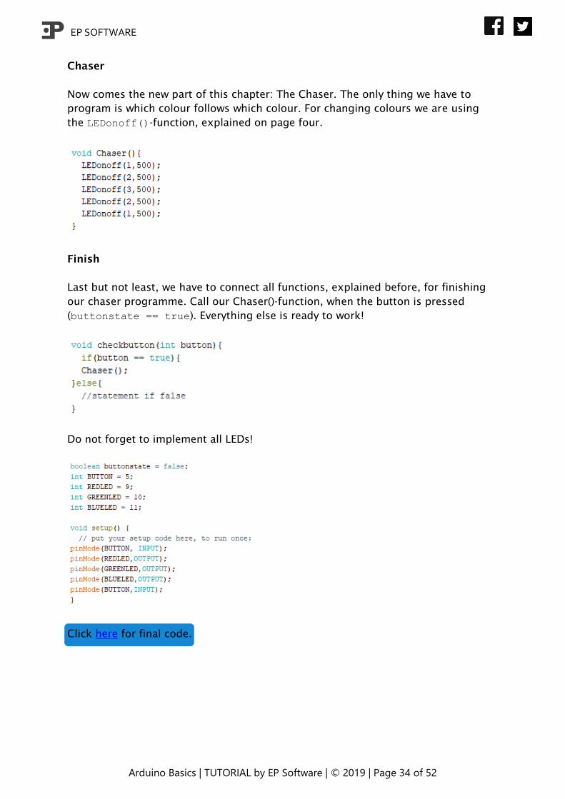
Chaser
Now comes the new part of this chapter: The Chaser. The only thing we have to
program is which colour follows which colour. For changing colours we are using
the LEDonoff()-function, explained on page four.
Finish
Last but not least, we have to connect all functions, explained before, for finishing
our chaser programme. Call our Chaser()-function, when the button is pressed
(buttonstate == true). Everything else is ready to work!
Do not forget to implement all LEDs!
Click here for final code.
EP SOFTWARE
Arduino Basics | TUTORIAL by EP Software | © 2019 | Page 35 of 52
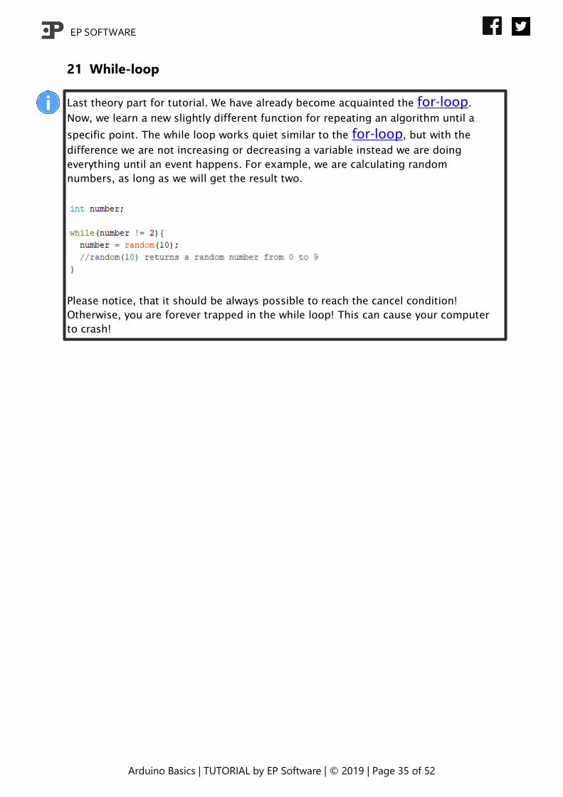
21 While-loop
Last theory part for tutorial. We have already become acquainted the for-loop.
Now, we learn a new slightly different function for repeating an algorithm until a
specific point. The while loop works quiet similar to the for-loop, but with the
difference we are not increasing or decreasing a variable instead we are doing
everything until an event happens. For example, we are calculating random
numbers, as long as we will get the result two.
Please notice, that it should be always possible to reach the cancel condition!
Otherwise, you are forever trapped in the while loop! This can cause your computer
to crash!
EP SOFTWARE
Arduino Basics | TUTORIAL by EP Software | © 2019 | Page 36 of 52
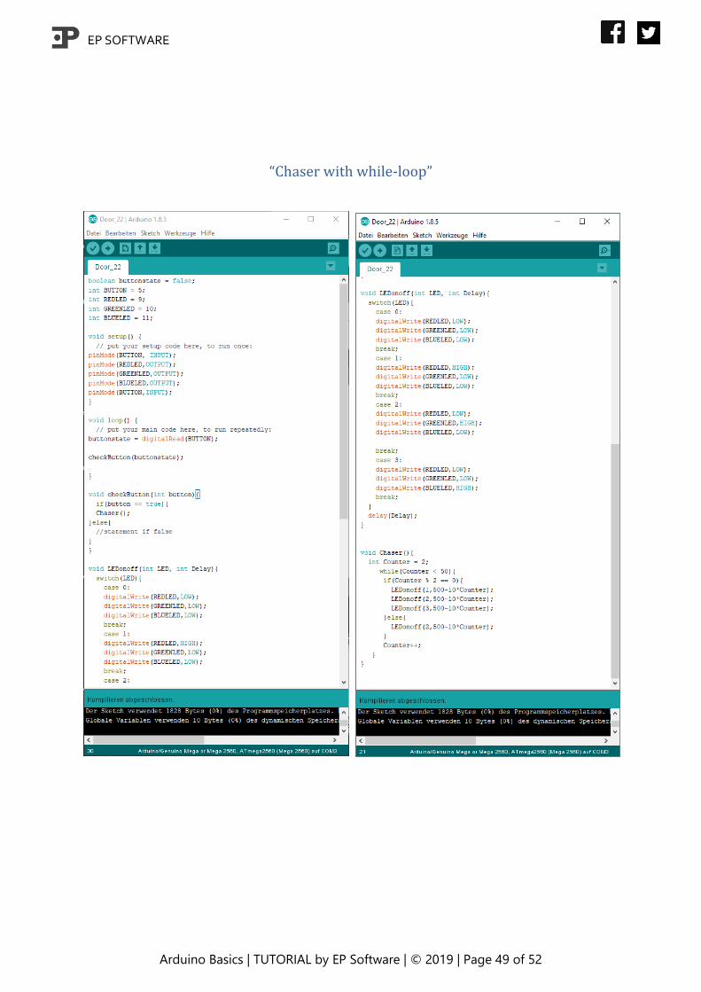
22 Chaser with while-loop
We will modify our chaser from chapter 20. Our goal is that the while-loop
controls how long our chase is going, after pressing the button. Last step of this
chapter is to change speed of the chase with progressing time.
We do not need to change anything from chapter 20 except for the Chaser()-
function. The while-loop controls the length of our chaser, but in the same time
we need the control variable (used as cancellation argument) also for running the
chaser back and forth (Red-Green-Blue-Green-Red).
As always, you have the chance to prove yourself and try it on your own first!
Hint: We need the mathematical operator: %. Instead of just dividing two
variables/numbers, it returns the decimal place. For example, 10 % 2 returns zero.
11 % 2 returns 0.5. This operator helps you to know, which way the chaser is going
(back or forth).
EP SOFTWARE
Arduino Basics | TUTORIAL by EP Software | © 2019 | Page 37 of 52
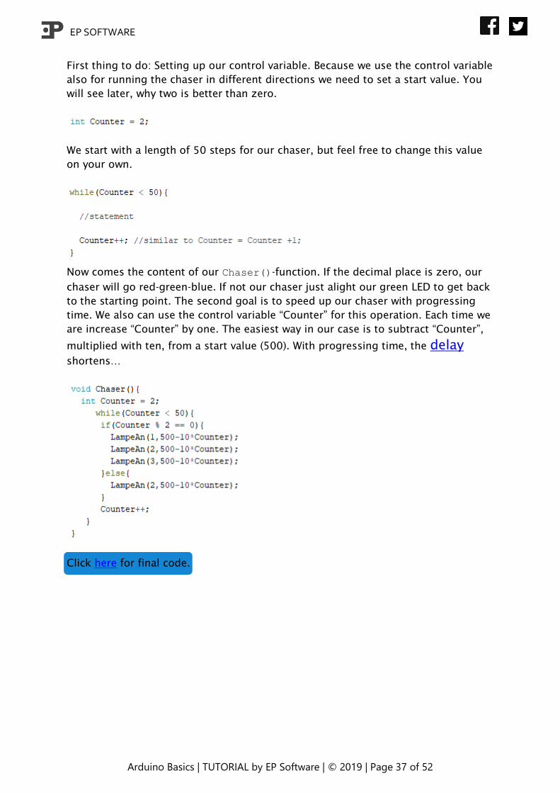
First thing to do: Setting up our control variable. Because we use the control variable
also for running the chaser in different directions we need to set a start value. You
will see later, why two is better than zero.
We start with a length of 50 steps for our chaser, but feel free to change this value
on your own.
Now comes the content of our Chaser()-function. If the decimal place is zero, our
chaser will go red-green-blue. If not our chaser just alight our green LED to get back
to the starting point. The second goal is to speed up our chaser with progressing
time. We also can use the control variable “Counter” for this operation. Each time we
are increase “Counter” by one. The easiest way in our case is to subtract “Counter”,
multiplied with ten, from a start value (500). With progressing time, the delay
shortens…
Click here for final code.
EP SOFTWARE
Arduino Basics | TUTORIAL by EP Software | © 2019 | Page 38 of 52
23 Chaser with while-loop and dimmer
We have learnt how to dim a LED, how to create a chaser and now we will combine
all this knowledge! Our goal is that we are running the same chaser like last chapter,
but every LED dims from HIGH to LOW before going to the next step.
Because you have all knowledge for this task, take your time to try it on your own.
Nevertheless, do not worry; we will give you some hints:
• Use last chapter´s sketch
• Use the for-loop for changing brightness
• Use very short delays to make decrease of the brightness visible
EP SOFTWARE
Arduino Basics | TUTORIAL by EP Software | © 2019 | Page 39 of 52
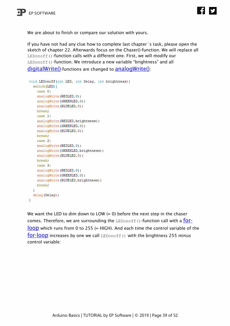
We are about to finish or compare our solution with yours.
If you have not had any clue how to complete last chapter´s task, please open the
sketch of chapter 22. Afterwards focus on the Chaser()-function. We will replace all
LEDonoff()-function calls with a different one. First, we will modify our
LEDonoff()-function. We introduce a new variable “brightness” and all
digitalWrite()-functions are changed to analogWrite():
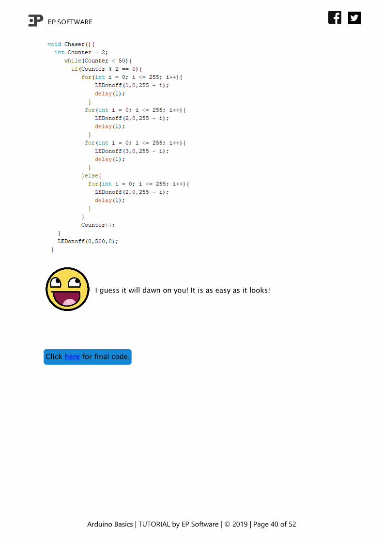
We want the LED to dim down to LOW (= 0) before the next step in the chaser
comes. Therefore, we are surrounding the LEDonoff()-function call with a for-
loop which runs from 0 to 255 (= HIGH). And each time the control variable of the
for-loop increases by one we call LEDonoff() with the brightness 255 minus
control variable:
EP SOFTWARE
Arduino Basics | TUTORIAL by EP Software | © 2019 | Page 40 of 52
I guess it will dawn on you! It is as easy as it looks!
Click here for final code.
EP SOFTWARE
Arduino Basics | TUTORIAL by EP Software | © 2019 | Page 41 of 52
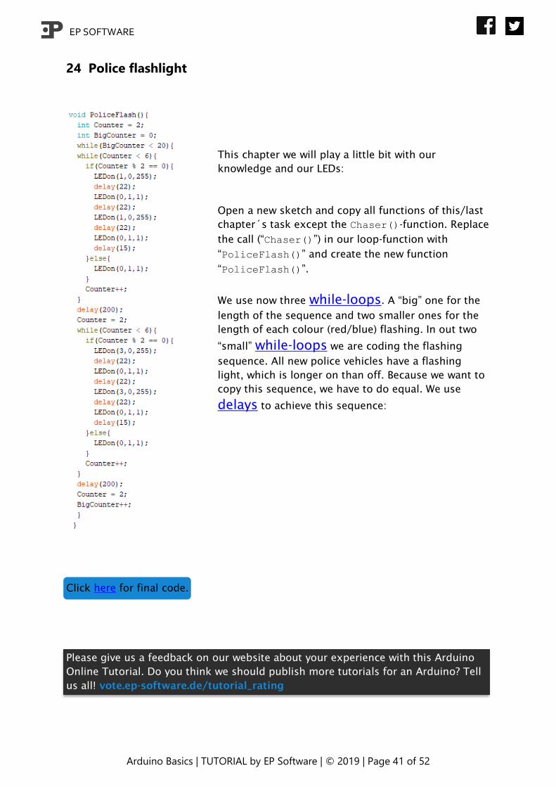
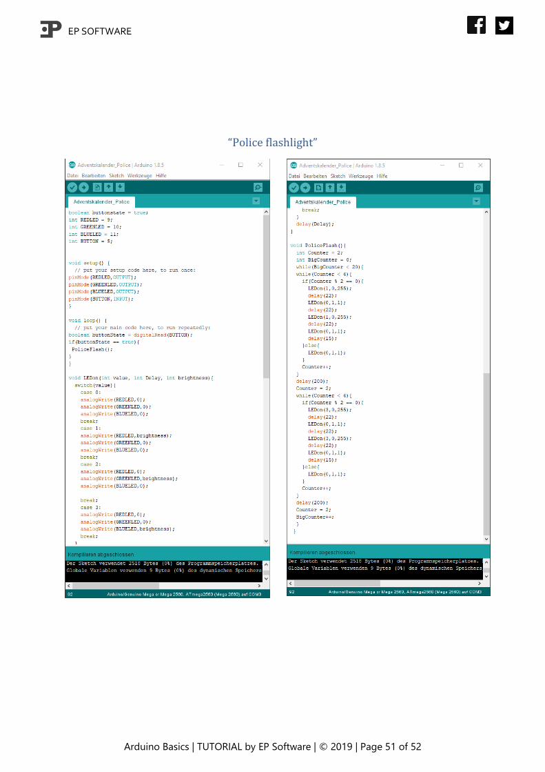
24 Police flashlight
This chapter we will play a little bit with our
knowledge and our LEDs:
Open a new sketch and copy all functions of this/last
chapter´s task except the Chaser()-function. Replace
the call (“Chaser()”) in our loop-function with
“PoliceFlash()” and create the new function
“PoliceFlash()”.
We use now three while-loops. A “big” one for the
length of the sequence and two smaller ones for the
length of each colour (red/blue) flashing. In out two
“small” while-loops we are coding the flashing
sequence. All new police vehicles have a flashing
light, which is longer on than off. Because we want to
copy this sequence, we have to do equal. We use
delays to achieve this sequence:
Click here for final code.
Please give us a feedback on our website about your experience with this Arduino
Online Tutorial. Do you think we should publish more tutorials for an Arduino? Tell
us all! vote.ep-software.de/tutorial_rating

EP SOFTWARE
Arduino Basics | TUTORIAL by EP Software | © 2019 | Page 42 of 52
Final codes
EP SOFTWARE
Arduino Basics | TUTORIAL by EP Software | © 2019 | Page 43 of 52
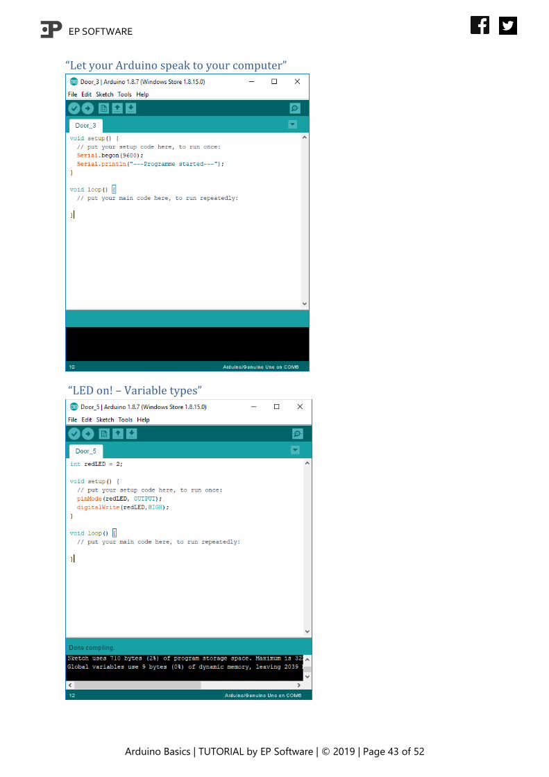
“Let your Arduino speak to your computer”
“LED on! – Variable types”
EP SOFTWARE
Arduino Basics | TUTORIAL by EP Software | © 2019 | Page 44 of 52
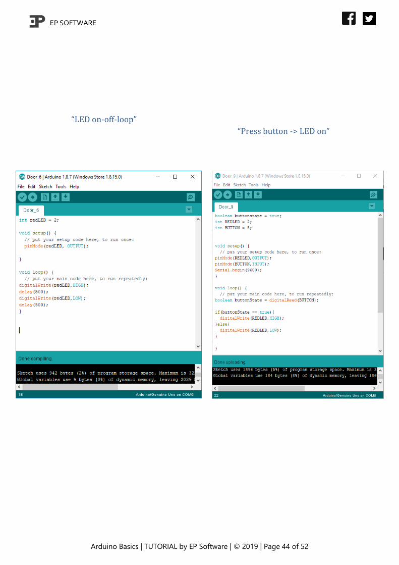
“LED on-off-loop”
“Press button -> LED on”
EP SOFTWARE
Arduino Basics | TUTORIAL by EP Software | © 2019 | Page 45 of 52
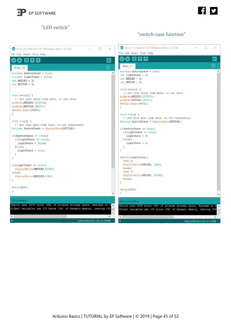
“LED switch”
“switch-case function”

EP SOFTWARE
Arduino Basics | TUTORIAL by EP Software | © 2019 | Page 46 of 52
“Traffic light”
“Dimmer”
EP SOFTWARE
Arduino Basics | TUTORIAL by EP Software | © 2019 | Page 47 of 52
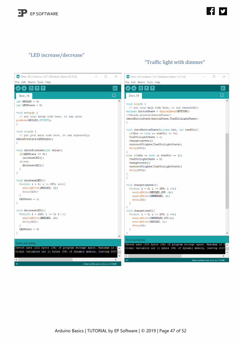
“LED increase/decrease”
“Traffic light with dimmer”
EP SOFTWARE
Arduino Basics | TUTORIAL by EP Software | © 2019 | Page 48 of 52
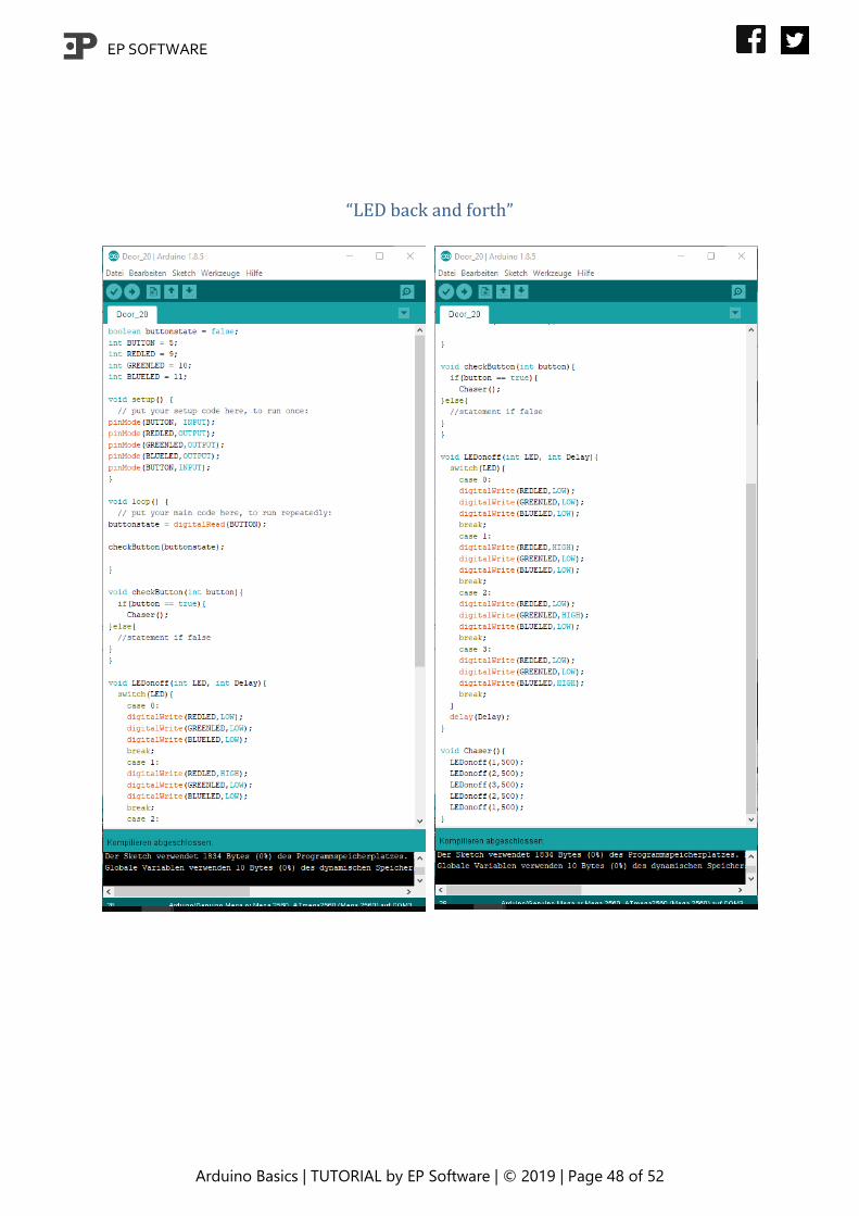
“LED back and forth”
EP SOFTWARE
Arduino Basics | TUTORIAL by EP Software | © 2019 | Page 49 of 52
“Chaser with while-loop”

EP SOFTWARE
Arduino Basics | TUTORIAL by EP Software | © 2019 | Page 50 of 52
“Chaser with while-loop and dimmer”
EP SOFTWARE
Arduino Basics | TUTORIAL by EP Software | © 2019 | Page 51 of 52
“Police flashlight”

EP SOFTWARE
Arduino Basics | TUTORIAL by EP Software | © 2019 | Page 52 of 52
References
Images:
https://openclipart.org/detail/130657/awesome
https://openclipart.org/detail/307315/info-icon-
rounded
https://openclipart.org/detail/215664/computer-
guy-meme
All other images Self-made. Parts of them may include images
under CC0 license.
Code:
All code Self-written