Arduino Multi-function Shield Projects · Arduino Multi-function Shield Projects...
30
Hackatronics Arduino Multi-function Shield Projects By Kashif Baig © 2019 cohesivecomputing.co.uk
Transcript of Arduino Multi-function Shield Projects · Arduino Multi-function Shield Projects...
Hackatronics
Arduino Multi-function ShieldProjects
By Kashif Baig© 2019 cohesivecomputing.co.uk
Arduino Multi-function Shield Projects cohesivecomputing.co.uk
Introducing Hackatronics – Coding for Fun.....................................................................................3Installing the Arduino multi-function shield library....................................................................3More about this series...................................................................................................................4More Challenging Projects...........................................................................................................4
Part 1 Basic Input / Output...............................................................................................................5Using the shield’s beeper.............................................................................................................5Detecting button presses on the shield.........................................................................................5Writing to the shield’s digit display.............................................................................................6Controlling the shield’s LED lights..............................................................................................7Reading the value of the shield’s potentiometer..........................................................................7
Part 2 Reading Sensors.....................................................................................................................9Counting pulses............................................................................................................................9Reading the temperature using an LM35 sensor........................................................................10Using an HC SR04 sonar module...............................................................................................10Getting data from an MPU6050 motion sensor..........................................................................11
Part 3 Real World Applications......................................................................................................14Countdown timer........................................................................................................................1424 Hour Alarm Clock.................................................................................................................15Heart monitor.............................................................................................................................19Surface incline indicator.............................................................................................................21Sonar ranger...............................................................................................................................23Speedometer...............................................................................................................................24
Appendices.....................................................................................................................................27Multi-function Shield Library Help...........................................................................................27MPU6050 Help...........................................................................................................................31

Arduino Multi-function Shield Projects cohesivecomputing.co.uk
Introducing Hackatronics – Coding for Fun
During the home computer revolution at the start of the ‘80s, my folks bought me a C64 computer, and very soon I was learning how to connect some basic components and sensors to its joystick and parallel ports to try and do some interesting things. This was way back in 1983. On one occasion, I actually managed to fry this £350 computer while soldering a wire that was connected to a port when it was switched on. Fortunately, I got the C64 repaired at minimal cost, but don’t try something like that yourself.
Today, the Raspberry Pi and Arduino range of microcontrollers is a great way to start to learn how to write code that connects with the outside world. In addition, there are numerous electronic add-ons with components already built on to them, ready to be utilized with a bit of code. One such add-on is a multi-function Arduino shield available at low cost from internet suppliers, one such being Hobby Components:
Simple I/O that is usually taken for granted on PCs, like reading key presses, outputting to a display, and sounding an alarm, often get in the way of the focus of the main task when developing for microcontrollers. It is for this reason I have developed a library for this multi-function shield that simplifies basic and mundane I/O operations. I also provide a set of real world applications that make use of this library as part of a coding series, so those new to coding on the Arduino can experiment with and enhance them. Well, that’s how I learnt how to code all those years ago.
Some familiarity with the Arduino platform is assumed, as is the installation of the Arduino development environment. A demo video of some of the Arduino applications is also available.
The correct URLs for this document and the projects are:
https://files.cohesivecomputing.co.uk/Hackatronics-Arduino-Multi-function-Shield.pdf https://www.cohesivecomputing.co.uk/hackatronics/
Please ensure you have downloaded the latest version of the document and source code samples. The coding examples are free for non-commercial use. If you find them helpful or useful in any way, please consider making a small donation to our Hackatronics fund, so we can continue developing interesting projects:
Installing the Arduino multi-function shield libraryIf you haven’t installed libraries before, first review instructions for installing Arduino libraries.
You can download the multi-function shield library from the link below and install as a .zip library, referring to the instructions in the link above:
Multi-function Shield Library
Hackatronics Page 3 of 30
Arduino Multi-function Shield Projects cohesivecomputing.co.uk
All source code used in series
Although we do everything to ensure our downloads are free from viruses and malware, please check that your virus and malware scanning software is up to date before hand.
It must be pointed out that by following the Hackatronics series, you agree to do so at your own risk, and agree to take full responsibility for any loss or damages you may incur upon yourself or others. If you’re a youngster starting out, be sure to have supervision of a responsible adult.
More about this seriesThis series is divided in to three main parts:
1. Basic Input / Output2. Reading Sensors3. Real World Applications
Part 1 demonstrates the ease with which the multi-function shield buttons, beeper and display can utilized by using the shield library, consequently making it easier to concentrate on the logic of the application.
Part 2 demonstrates how the shield library can be used to read values from external sensors, such as temperature, sonar and motion sensors, and how to process electronic pulses from an external source.
Part 3 explores working applications using the library and the multi-function shield:
24 hour alarm clock Heart monitor – (requires heart pulse sensor) Count down timer Surface incline level indicator– (requires MPU6050 motion sensor) Sonar ranger – (requires HC SR04 sonar module) Speedometer – (requires magnet and reed switch)
Each of these has scope to be built upon and expanded, but I leave that to you.
More Challenging ProjectsHave a look at our other projects, some of which are for the more experienced enthusiast. Have fun coding!
Arduino Multi-function Shield Bonus Sketches Arduino Web Server – Develop IoT Web Apps Using MVC Design Arduino LCD Shield – Coding Menus the Easy Way Android and Arduino Coding Fun Arduino IoT Remote Data Collection and Visualization
Hackatronics Page 4 of 30
Arduino Multi-function Shield Projects cohesivecomputing.co.uk
Part 1 Basic Input / Output
This is part one of the Applied Hackatronics Series for the Arduino Multi-function shield, which shows how to use the shield library to access the multi-function shield buttons, buzzer and display. If you haven’t already done so, you’ll need to download the source code and install the libraries using the links in the introduction.
By following the Hackatronics series, you agree to do so at your own risk, and agree to take full responsibility for any loss or damages you may incur upon yourself or others.
Using the shield’s beeperThe multi-function shield library provides a flexible way to sound different types of alarms using the beeper. The actual timing and sounding of the beeper is controlled in the background using interrupts, which means your application can continue to focus on performing its main task.
#include <MultiFuncShield.h>
void setup() { // put your setup code here, to run once:
MFS.initialize(); // initialize multi-function shield library // NOTE beep control is performed in the background, i.e. beep() is non blocking. // short beep for 200 milliseconds MFS.beep(); delay(1000); // 4 short beeps, repeated 3 times. MFS.beep(5, // beep for 50 milliseconds 5, // silent for 50 milliseconds 4, // repeat above cycle 4 times 3, // loop 3 times 50 // wait 500 milliseconds between loop );}
void loop() { // put your main code here, to run repeatedly:
}
Detecting button presses on the shieldWith the multi-function shield library, different types of button presses can be detected: short press, long press, button release after short press, button release after long press. The sketch below displays the type of button press in the serial monitor window. Check what happens you press and or hold multiple buttons together, and for different durations.
#include <MultiFuncShield.h>
void setup() { // put your setup code here, to run once: Serial.begin(9600); MFS.initialize(); // initialize multi-function shield library}
Hackatronics Page 5 of 30
Arduino Multi-function Shield Projects cohesivecomputing.co.uk
void loop() { // put your main code here, to run repeatedly:
byte btn = MFS.getButton(); // Normally it is sufficient to compare the return // value to predefined macros, e.g. BUTTON_1_PRESSED, // BUTTON_1_LONG_PRESSED etc. if (btn) { byte buttonNumber = btn & B00111111; byte buttonAction = btn & B11000000; Serial.print("BUTTON_"); Serial.write(buttonNumber + '0'); Serial.print("_"); if (buttonAction == BUTTON_PRESSED_IND) { Serial.println("PRESSED"); } else if (buttonAction == BUTTON_SHORT_RELEASE_IND) { Serial.println("SHORT_RELEASE"); } else if (buttonAction == BUTTON_LONG_PRESSED_IND) { Serial.println("LONG_PRESSED"); } else if (buttonAction == BUTTON_LONG_RELEASE_IND) { Serial.println("LONG_RELEASE"); } }}
Writing to the shield’s digit displayThe management of the multi-function shield’s digit display is performed in the background using interrupts, which means your application can continue to focus on performing its main task. String, integer and float values are written to the display as demonstrated in the sketch below:
#include <MultiFuncShield.h>
void setup() { // put your setup code here, to run once: MFS.initialize(); // initialize multi-function shield library MFS.write("Hi"); delay(2000); MFS.write(-273); delay(2000); MFS.write(3.141, 2); // display to 2 decimal places. delay(2000);}
int counter=0;byte ended = false;
void loop() { // put your main code here, to run repeatedly:
if (counter < 200) { MFS.write((int)counter); counter++; } else if (!ended) {
Hackatronics Page 6 of 30
Arduino Multi-function Shield Projects cohesivecomputing.co.uk
ended = true; MFS.write("End"); MFS.blinkDisplay(DIGIT_ALL, ON); } delay(50);}
Controlling the shield’s LED lightsAlthough it isn’t strictly necessary to use the multi-function shield library to control the LED lights of the shield, support is provided in cases where your application needs the LEDs to perform basic blink operations. Blinking is managed in the background using interrupts.
#include <MultiFuncShield.h>
void setup() { // put your setup code here, to run once: MFS.initialize(); // initialize multi-function shield library MFS.writeLeds(LED_ALL, ON); delay(2000); MFS.blinkLeds(LED_1 | LED_2, ON); delay(2000); MFS.blinkLeds(LED_1 | LED_2, OFF); MFS.blinkLeds(LED_3 | LED_4, ON); delay(2000); MFS.blinkLeds(LED_ALL, ON); delay(2000); MFS.blinkLeds(LED_ALL, OFF); MFS.writeLeds(LED_ALL, OFF);}
void loop() { // put your main code here, to run repeatedly:
}
Reading the value of the shield’s potentiometerThis sketch demonstrates how the value of the preset pot is read and displayed on the multi-functionshield. After uploading this sketch, turn the screw of the potentiometer to see the reading change on the digit display.
#include <MultiFuncShield.h>
void setup() { // put your setup code here, to run once:
MFS.initialize(); // initialize multi-function shield library}
void loop() { // put your main code here, to run repeatedly:
MFS.write(analogRead(POT_PIN)); delay(100);}
All the code samples and applications have been tested and work. If you experience any difficulties,please leave a comment, and I’ll get back to you as soon as I can.
Hackatronics Page 7 of 30
Arduino Multi-function Shield Projects cohesivecomputing.co.uk
Part 2 Reading Sensors
This is part two of the Applied Hackatronics Series for the Arduino Multi-function shield, and shows how the multi-function shield library can be used to read values from external sensors, such as temperature, sonar and motion sensors, and how to process electronic pulses from an external source. If you haven’t already done so, you’ll need to download the source code and install the libraries using the links in the introduction.
By following the Hackatronics series, you agree to do so at your own risk, and agree to take full responsibility for any loss or damages you may incur upon yourself or others.
Counting pulsesThe multi-function shield library has support for counting pulses (up to 500Hz) applied to an input pin of the Arduino. The counting of pulses is managed in the background using interrupts, which allows your application to focus on performing its main task. After uploading this sketch, repeatedlypress button 1 to generate the pulses and see a reading of the press rate on the digit display.
#include <MultiFuncShield.h>
void setup() { // put your setup code here, to run once:
MFS.initialize(); // initialize multi-function shield library MFS.initPulseInCounter( BUTTON_1_PIN, // use button 1 as means of generating pulses. 1500, // the number of milliseconds to wait for a pulse, beforeresetting pulse in period to 0. LOW // trigger pulse on LOW input. );}
void loop() { // put your main code here, to run repeatedly:
// Get the period of the most recent pulse (in milliseconds). // NOTE: pulse measurements are actually performed using interrupts. unsigned int pulsePeriodMs = MFS.getPulseInPeriod(); if (pulsePeriodMs == 0) { MFS.write(0.0, 1); } else { MFS.write(1000.0 / pulsePeriodMs, 1); // calculate pulses per second. Displayto 1 decimal place. }}
Hackatronics Page 8 of 30
Arduino Multi-function Shield Projects cohesivecomputing.co.uk
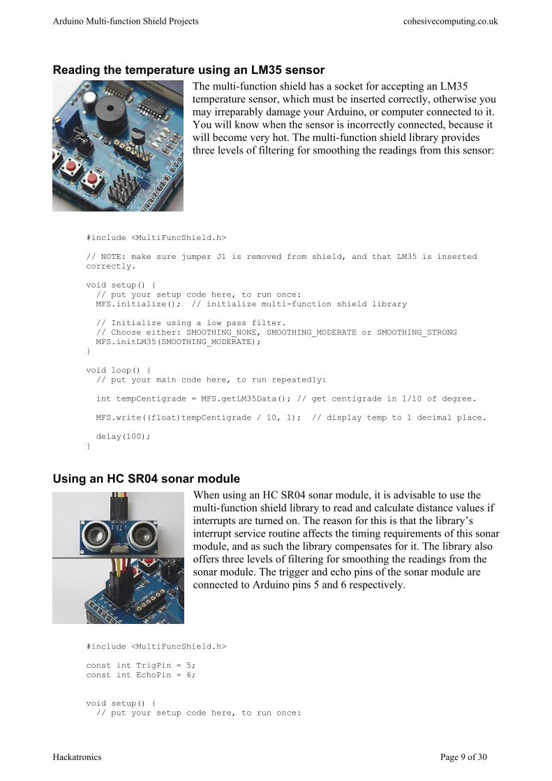
Reading the temperature using an LM35 sensorThe multi-function shield has a socket for accepting an LM35 temperature sensor, which must be inserted correctly, otherwise you may irreparably damage your Arduino, or computer connected to it. You will know when the sensor is incorrectly connected, because it will become very hot. The multi-function shield library provides three levels of filtering for smoothing the readings from this sensor:
#include <MultiFuncShield.h>
// NOTE: make sure jumper J1 is removed from shield, and that LM35 is inserted correctly.
void setup() { // put your setup code here, to run once: MFS.initialize(); // initialize multi-function shield library // Initialize using a low pass filter. // Choose either: SMOOTHING_NONE, SMOOTHING_MODERATE or SMOOTHING_STRONG MFS.initLM35(SMOOTHING_MODERATE);}
void loop() { // put your main code here, to run repeatedly:
int tempCentigrade = MFS.getLM35Data(); // get centigrade in 1/10 of degree. MFS.write((float)tempCentigrade / 10, 1); // display temp to 1 decimal place. delay(100);}
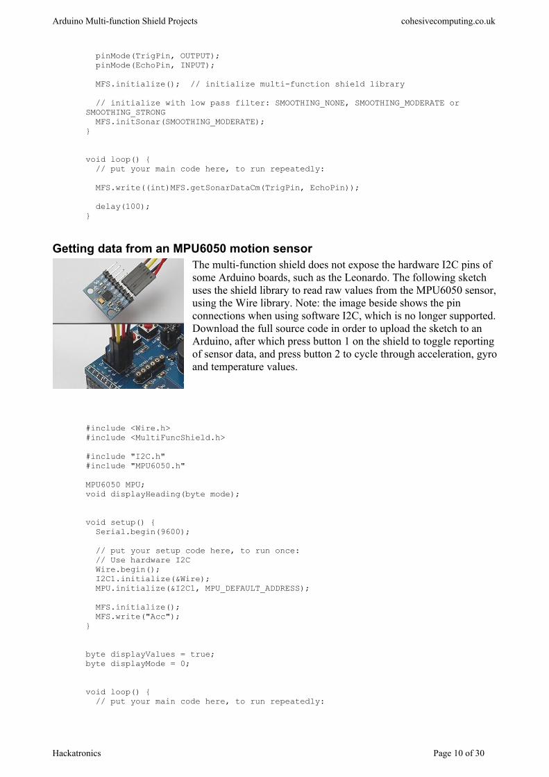
Using an HC SR04 sonar moduleWhen using an HC SR04 sonar module, it is advisable to use the multi-function shield library to read and calculate distance values if interrupts are turned on. The reason for this is that the library’s interrupt service routine affects the timing requirements of this sonarmodule, and as such the library compensates for it. The library also offers three levels of filtering for smoothing the readings from the sonar module. The trigger and echo pins of the sonar module are connected to Arduino pins 5 and 6 respectively.
#include <MultiFuncShield.h>
const int TrigPin = 5;const int EchoPin = 6;
void setup() { // put your setup code here, to run once:
Hackatronics Page 9 of 30
Arduino Multi-function Shield Projects cohesivecomputing.co.uk
pinMode(TrigPin, OUTPUT); pinMode(EchoPin, INPUT); MFS.initialize(); // initialize multi-function shield library // initialize with low pass filter: SMOOTHING_NONE, SMOOTHING_MODERATE or SMOOTHING_STRONG MFS.initSonar(SMOOTHING_MODERATE);}
void loop() { // put your main code here, to run repeatedly:
MFS.write((int)MFS.getSonarDataCm(TrigPin, EchoPin)); delay(100);}
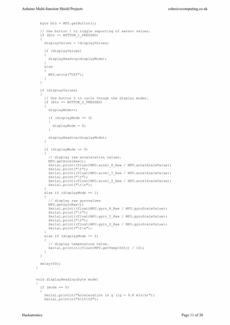
Getting data from an MPU6050 motion sensorThe multi-function shield does not expose the hardware I2C pins of some Arduino boards, such as the Leonardo. The following sketch uses the shield library to read raw values from the MPU6050 sensor,using the Wire library. Note: the image beside shows the pin connections when using software I2C, which is no longer supported.Download the full source code in order to upload the sketch to an Arduino, after which press button 1 on the shield to toggle reporting of sensor data, and press button 2 to cycle through acceleration, gyroand temperature values.
#include <Wire.h>#include <MultiFuncShield.h>
#include "I2C.h"#include "MPU6050.h"
MPU6050 MPU;void displayHeading(byte mode);
void setup() { Serial.begin(9600); // put your setup code here, to run once: // Use hardware I2C Wire.begin(); I2C1.initialize(&Wire); MPU.initialize(&I2C1, MPU_DEFAULT_ADDRESS);
MFS.initialize(); MFS.write("Acc");}
byte displayValues = true;byte displayMode = 0;
void loop() { // put your main code here, to run repeatedly:
Hackatronics Page 10 of 30
Arduino Multi-function Shield Projects cohesivecomputing.co.uk
byte btn = MFS.getButton();
// Use button 1 to toggle reporting of sensor values. if (btn == BUTTON_1_PRESSED) { displayValues = !displayValues; if (displayValues) { displayHeading(displayMode); } else { MFS.write("Off"); } } if (displayValues) { // Use button 2 to cycle though the display modes. if (btn == BUTTON_2_PRESSED) { displayMode++; if (displayMode == 3) { displayMode = 0; } displayHeading(displayMode); } if (displayMode == 0) { // display raw acceleration values. MPU.getAccelRaw(); Serial.print((float)MPU.accel_X_Raw / MPU.accelScaleValue); Serial.print("\t"); Serial.print((float)MPU.accel_Y_Raw / MPU.accelScaleValue); Serial.print("\t"); Serial.print((float)MPU.accel_Z_Raw / MPU.accelScaleValue); Serial.print("\t\n"); } else if (displayMode == 1) { // display raw gyrovalues MPU.getGyroRaw(); Serial.print((float)MPU.gyro_X_Raw / MPU.gyroScaleValue); Serial.print("\t"); Serial.print((float)MPU.gyro_Y_Raw / MPU.gyroScaleValue); Serial.print("\t"); Serial.print((float)MPU.gyro_Z_Raw / MPU.gyroScaleValue); Serial.print("\t\n"); } else if (displayMode == 2) { // display temperature value. Serial.println((float)MPU.getTemp10th() / 10); } } delay(50);}
void displayHeading(byte mode){ if (mode == 0) { Serial.println("Acceleration in g (1g = 9.8 m/s/s)"); Serial.println("X\tY\tZ");
Hackatronics Page 11 of 30
Arduino Multi-function Shield Projects cohesivecomputing.co.uk
MFS.write("Acc"); } else if (mode == 1) { Serial.println("Gyro angular velocity in degrees / second"); Serial.println("X\tY\tZ"); MFS.write("Gyro"); } else if (mode == 2) { Serial.println("Temperature in degrees celsius."); MFS.write("Te"); }}
All the code samples and applications have been tested and work. If you experience any difficulties,please leave a comment, and I’ll get back to you as soon as I can.
Hackatronics Page 12 of 30
Arduino Multi-function Shield Projects cohesivecomputing.co.uk
Part 3 Real World Applications
This is part three of the Applied Hackatronics Series for the Arduino Multi-function shield, and explores working applications using the library and the multi-function shield. If you haven’t alreadydone so, you’ll need to download the source code and install the libraries using the links in the introduction.
For each of the applications below there is an accompanying online video, as well as a summary video.
By following the Hackatronics series, you agree to do so at your own risk, and agree to take full responsibility for any loss or damages you may incur upon yourself or others.
Countdown timer
This countdown timer is similar to a countdown timer you might find in a microwave oven. You setthe time, start the countdown timer, and when it reaches zero, the alarm sounds. You can pause/continue the timer, and reset to zero. Use the multi-function shield buttons 2 and 3 to set the minutes and seconds. A short press of button 1 starts or stops the timer, and a long press resets it. Possible enhancements for this application are to have a device switched on only whilst the timer is counting down.
#include <MultiFuncShield.h>
enum CountDownModeValues{ COUNTING_STOPPED, COUNTING};
byte countDownMode = COUNTING_STOPPED;
byte tenths = 0;char seconds = 0;char minutes = 0;
void setup() { // put your setup code here, to run once: MFS.initialize(); // initialize multi-function shield library MFS.write(0); Serial.begin(9600);}
void loop() { // put your main code here, to run repeatedly:
byte btn = MFS.getButton(); switch (countDownMode) { case COUNTING_STOPPED: if (btn == BUTTON_1_SHORT_RELEASE && (minutes + seconds) > 0) { // start the timer countDownMode = COUNTING; } else if (btn == BUTTON_1_LONG_PRESSED) {
Hackatronics Page 13 of 30
Arduino Multi-function Shield Projects cohesivecomputing.co.uk
// reset the timer tenths = 0; seconds = 0; minutes = 0; MFS.write(minutes*100 + seconds); } else if (btn == BUTTON_2_PRESSED || btn == BUTTON_2_LONG_PRESSED) { minutes++; if (minutes > 60) { minutes = 0; } MFS.write(minutes*100 + seconds); } else if (btn == BUTTON_3_PRESSED || btn == BUTTON_3_LONG_PRESSED) { seconds += 10; if (seconds >= 60) { seconds = 0; } MFS.write(minutes*100 + seconds); } break; case COUNTING: if (btn == BUTTON_1_SHORT_RELEASE || btn == BUTTON_1_LONG_RELEASE) { // stop the timer countDownMode = COUNTING_STOPPED; } else { // continue counting down tenths++; if (tenths == 10) { tenths = 0; seconds--; if (seconds < 0 && minutes > 0) { seconds = 59; minutes--; } if (minutes == 0 && seconds == 0) { // timer has reached 0, so sound the alarm MFS.beep(50, 50, 3); // beep 3 times, 500 milliseconds on / 500 off countDownMode = COUNTING_STOPPED; } MFS.write(minutes*100 + seconds); } delay(100); } break; }}
24 Hour Alarm Clock
This application demonstrates a digital clock with an alarm capability. When the Arduino is powered on, the multi-function shield display flashes until the user sets the time. Hold button 1 to set the time or alarm. When setting the time use button 3 to set the hour or minutes. Press button 2
Hackatronics Page 14 of 30
Arduino Multi-function Shield Projects cohesivecomputing.co.uk
to view alarm time or cancel the alarm if in progress. Holding button 3 enables or disables the alarm(LED1 indicates alarm is enabled). Possible enhancements to this application are to have a snooze feature, or to have multiple on/off periods during the day for a device.
#include <MultiFuncShield.h>
/* button 1 : hold to set time or alarm button 2 : press to view alarm time or cancel alarm if in progress button 3 : increment hour / minute when setting (alarm) time. Hold to toggle alarm setting. LED1 : on = alarm enabled*/
volatile unsigned int clockMilliSeconds = 0;volatile byte clockSeconds = 0;volatile byte clockMinutes = 0;volatile byte clockHours = 12;volatile byte clockEnabled = 1;
byte alarmMinutes = 30;byte alarmHours = 6;volatile byte alarmEnabled = false;
byte alarmTogglePressed = false;
enum displayModeValues{ MODE_CLOCK_TIME, MODE_CLOCK_TIME_SET_HOUR, MODE_CLOCK_TIME_SET_MINUTE, MODE_ALARM_TIME, MODE_ALARM_TIME_SET_HOUR, MODE_ALARM_TIME_SET_MINUTE};
byte displayMode = MODE_CLOCK_TIME;
//-------------------------------------------------------------------------------void setup(){ MFS.userInterrupt = clockISR; MFS.initialize(); MFS.blinkDisplay(DIGIT_ALL); //MFS.beep(500);}
void loop(){ // put your main code here, to run repeatedly: byte btn = MFS.getButton(); switch (displayMode) { case MODE_CLOCK_TIME: displayTime(clockHours, clockMinutes); if (btn == BUTTON_2_PRESSED) { MFS.beep(0); // cancel the alarm. displayMode = MODE_ALARM_TIME; } else if (btn == BUTTON_1_LONG_PRESSED) { MFS.blinkDisplay(DIGIT_ALL, OFF);
Hackatronics Page 15 of 30

Arduino Multi-function Shield Projects cohesivecomputing.co.uk
MFS.blinkDisplay(DIGIT_1 | DIGIT_2); displayMode = MODE_CLOCK_TIME_SET_HOUR; clockEnabled = false; clockMilliSeconds = 0; clockSeconds = 0; } else if (btn == BUTTON_3_LONG_PRESSED && !alarmTogglePressed) { alarmTogglePressed = true; alarmEnabled = !alarmEnabled; MFS.writeLeds(LED_1, alarmEnabled); } else if (btn == BUTTON_3_LONG_RELEASE) { alarmTogglePressed = false; } break; case MODE_CLOCK_TIME_SET_HOUR: if (btn == BUTTON_1_PRESSED) { MFS.blinkDisplay(DIGIT_1 | DIGIT_2, OFF); MFS.blinkDisplay(DIGIT_3 | DIGIT_4); displayMode = MODE_CLOCK_TIME_SET_MINUTE; } else if (btn == BUTTON_3_PRESSED || btn == BUTTON_3_LONG_PRESSED) { clockHours++; if (clockHours >= 24) { clockHours = 0; } displayTime(clockHours, clockMinutes); } break; case MODE_CLOCK_TIME_SET_MINUTE: if (btn == BUTTON_1_PRESSED) { MFS.blinkDisplay(DIGIT_3 | DIGIT_4, OFF); displayMode = MODE_CLOCK_TIME; clockEnabled = true; } else if (btn == BUTTON_3_PRESSED || btn == BUTTON_3_LONG_PRESSED) { clockMinutes++; if (clockMinutes >= 60) { clockMinutes = 0; } displayTime(clockHours, clockMinutes); } break; case MODE_ALARM_TIME: displayTime(alarmHours, alarmMinutes);
if (btn == BUTTON_2_SHORT_RELEASE || btn == BUTTON_2_LONG_RELEASE) { displayMode = MODE_CLOCK_TIME; } else if (btn == BUTTON_1_LONG_PRESSED) { MFS.blinkDisplay(DIGIT_ALL, OFF); MFS.blinkDisplay(DIGIT_1 | DIGIT_2); displayMode = MODE_ALARM_TIME_SET_HOUR; alarmEnabled = false; } break; case MODE_ALARM_TIME_SET_HOUR:
Hackatronics Page 16 of 30
Arduino Multi-function Shield Projects cohesivecomputing.co.uk
if (btn == BUTTON_1_PRESSED) { MFS.blinkDisplay(DIGIT_1 | DIGIT_2, OFF); MFS.blinkDisplay(DIGIT_3 | DIGIT_4); displayMode = MODE_ALARM_TIME_SET_MINUTE; } else if (btn == BUTTON_3_PRESSED || btn == BUTTON_3_LONG_PRESSED) { alarmHours++; if (alarmHours >= 24) { alarmHours = 0; } displayTime(alarmHours, alarmMinutes); } break; case MODE_ALARM_TIME_SET_MINUTE: if (btn == BUTTON_1_PRESSED) { MFS.blinkDisplay(DIGIT_3 | DIGIT_4, OFF); displayMode = MODE_CLOCK_TIME; alarmEnabled = true; MFS.writeLeds(LED_1, ON); } else if (btn == BUTTON_3_PRESSED || btn == BUTTON_3_LONG_PRESSED) { alarmMinutes++; if (alarmMinutes >= 60) { alarmMinutes = 0; } displayTime(alarmHours, alarmMinutes); } break; }}
void displayTime (byte hours, byte minutes){ char time[5]; sprintf(time, "%03d", (hours * 100) + minutes); MFS.write(time, 1);}
//--------------------------------------------------------------------------------void clockISR (){ // Perform ripple count for all time components. if (clockEnabled) { clockMilliSeconds++; if (clockMilliSeconds >= 1000) { clockMilliSeconds = 0; clockSeconds++; if (clockSeconds >= 60) { clockSeconds = 0; clockMinutes++; if (clockMinutes >= 60) { clockMinutes = 0; clockHours++; if (clockHours >= 24) {
Hackatronics Page 17 of 30
Arduino Multi-function Shield Projects cohesivecomputing.co.uk
clockHours = 0; } } // If current time coincides with alarm time, and alarm is enabled, engagethe alarm. if (alarmEnabled && (clockMinutes == alarmMinutes) && (clockHours == alarmHours)) { MFS.beep( 10, // on period 5, // off period 4, // number of cycles 100, // number of loop cycles 50 // delay between loop cycles ); } } } }}
Heart monitor
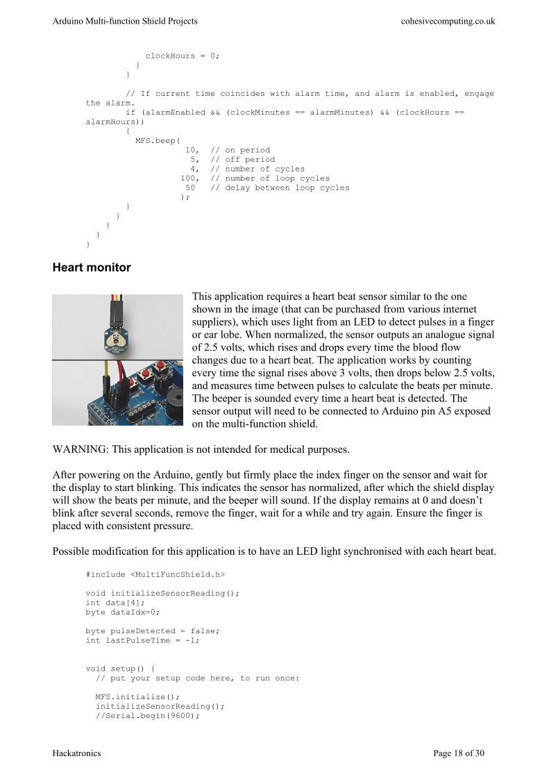
This application requires a heart beat sensor similar to the one shown in the image (that can be purchased from various internet suppliers), which uses light from an LED to detect pulses in a finger or ear lobe. When normalized, the sensor outputs an analogue signalof 2.5 volts, which rises and drops every time the blood flow changes due to a heart beat. The application works by counting every time the signal rises above 3 volts, then drops below 2.5 volts,and measures time between pulses to calculate the beats per minute. The beeper is sounded every time a heart beat is detected. The sensor output will need to be connected to Arduino pin A5 exposed on the multi-function shield.
WARNING: This application is not intended for medical purposes.
After powering on the Arduino, gently but firmly place the index finger on the sensor and wait for the display to start blinking. This indicates the sensor has normalized, after which the shield display will show the beats per minute, and the beeper will sound. If the display remains at 0 and doesn’t blink after several seconds, remove the finger, wait for a while and try again. Ensure the finger is placed with consistent pressure.
Possible modification for this application is to have an LED light synchronised with each heart beat.
#include <MultiFuncShield.h>
void initializeSensorReading();int data[4];byte dataIdx=0;
byte pulseDetected = false;int lastPulseTime = -1;
void setup() { // put your setup code here, to run once: MFS.initialize(); initializeSensorReading(); //Serial.begin(9600);
Hackatronics Page 18 of 30

Arduino Multi-function Shield Projects cohesivecomputing.co.uk
}
void loop(){ if (MFS.getTimer() == 0) { MFS.setTimer(10000); // reset millisecond countdown timer. if (lastPulseTime != -1) { lastPulseTime = 10000 + lastPulseTime; } } int sensorValue = analogRead(A5); // read the sensor. if (sensorValue < 20 || sensorValue > 970) { // Sensor hasn't normalized, check how long for in milliseconds. if (lastPulseTime != -1 && lastPulseTime - MFS.getTimer() > 700) { initializeSensorReading(); } } else if (sensorValue > (3 * 1024) / 5) // value is rising, so must be start of a pulse. { if (!pulseDetected) { pulseDetected = true; if (lastPulseTime == -1) { lastPulseTime = MFS.getTimer(); } else { int pulsePeriod = lastPulseTime - MFS.getTimer(); // calculate time between pulses in millseconds. lastPulseTime = MFS.getTimer(); int bpm = 60000 / pulsePeriod; // calculate beats per minute. if (bpm < 45 || bpm > 230) // bpm is outside acceptible range, so clear the data buffer. { initializeSensorReading(); } else { // bpm is within range, but still need to calculate average. data[dataIdx++] = bpm; if (dataIdx >= 4) { dataIdx = 0; } if (data[0] && data[1] && data[2] && data[3]) // check if data buffer is full before calculating avg bpm. { int avgBpm = (data[0] + data[1] + data[2] + data[3]) / 4; MFS.blinkDisplay(DIGIT_ALL, OFF); MFS.write(avgBpm); MFS.beep(); } else { // buffer not full, so blink the display.
Hackatronics Page 19 of 30
Arduino Multi-function Shield Projects cohesivecomputing.co.uk
MFS.blinkDisplay(DIGIT_ALL, ON); } } } } } else if (sensorValue < (1024 / 2)) // value is falling, so must be end of pulse. { pulseDetected = false; } //Serial.println(sensorValue); //delay(10);}
// Initialize the read buffer and display.void initializeSensorReading(){ lastPulseTime = 0; dataIdx = 0; for (int i=0; i<4; i++) { data[i] = 0; } MFS.write(0); MFS.blinkDisplay(DIGIT_ALL, OFF);}
Surface incline indicator
The surface incline indicator application uses the MPU6050 motion sensor to determine the angle ofinclination of a flat surface. You will need to download the full source code before uploading to the Arduino. This application has only been tested to work with Arduino Uno, using pins A4 and A5 for SDA and SCL respectively .
After powering on the Arduino, place the motion sensor on a surface that is as level as possible, then press and hold button 1 on the multi-function shield. LED 1 blinks while the sensor is calibrated. Thereafter, by placing the motion sensor on inclined surfaces the shield will display the angle of inclination.
Presently the incline is displayed only for a single axis, but the application could modified to the show the incline for an additional axis.
#include <Wire.h>#include <MultiFuncShield.h>
#include "I2C.h"#include "MPU6050.h"
void calibrate();
MPU6050 MPU;
const float radToDeg = 180.0 / 3.1415926535897932384626433832795;int xOffset=0, yOffset=0;float zScaleOffset = 1; // multiply Z axis with this value to get as close to 1g as possible.
Hackatronics Page 20 of 30
Arduino Multi-function Shield Projects cohesivecomputing.co.uk
void setup() { // put your setup code here, to run once:
// Use hardware I2C Wire.begin(); I2C1.initialize(&Wire); MPU.initialize(&I2C1, MPU_DEFAULT_ADDRESS, ACCEL_FS_2, GYRO_FS_250, DLPF_BW_5);
}
void loop() { // put your main code here, to run repeatedly:
byte btn = MFS.getButton(); if (btn == BUTTON_1_LONG_PRESSED) { calibrate(); } MPU.getAccelRaw(); MPU.accel_X_Raw -= xOffset; MPU.accel_Y_Raw -= yOffset; float angle; if (MPU.accel_Z_Raw == 0) { angle = 90; } else { angle = atan((float)MPU.accel_Y_Raw / (MPU.accel_Z_Raw * zScaleOffset)) * radToDeg; // calculate for y axis //angle = atan((float)MPU.accel_X_Raw / (MPU.accel_Z_Raw * zScaleOffset)) * radToDeg; // calculate for X axis } MFS.write(angle, 1); delay(200);}
void calibrate(){ MFS.write(" "); MFS.writeLeds(LED_1, ON); MFS.blinkLeds(LED_1, ON); // discard first few sensor readings. for (int i=0; i<10; i++) { MPU.getAccelRaw(); delay(10); } int xValues[5], yValues[5], zValues[5]; for (int i=0; i<5; i++) { MPU.getAccelRaw(); xValues[i] = MPU.accel_X_Raw; yValues[i] = MPU.accel_Y_Raw; zValues[i] = MPU.accel_Z_Raw; delay(300); } xOffset = MedianOf5(xValues[0], xValues[1], xValues[2], xValues[3], xValues[4]); yOffset = MedianOf5(yValues[0], yValues[1], yValues[2], yValues[3], yValues[4]);
zScaleOffset = (float)MPU.accelScaleValue / MedianOf5(zValues[0], zValues[1], zValues[2], zValues[3], zValues[4]);
Hackatronics Page 21 of 30
Arduino Multi-function Shield Projects cohesivecomputing.co.uk
MFS.blinkLeds(LED_1, OFF); // clear the input button buffer by reading it and discarding value. for (int i=0; i<10; i++) { MFS.getButton(); }}
Sonar ranger
The sonar ranger application uses the HC SR04 sonar module to measure distance between the module and a solid object up to 5 meters away. This application works in a way similar to the obstacle sensor of some vehicles that assist the driver in parking manoeuvres. As an obstacle nears the sonar module, the beeper is sounded at shorter and shorter intervals. The shield’s button 1 is used for engaging or disengaging the sonar module.
The trigger and echo pins of the sonar module are connected to Arduino pins 5 and 6 respectively, which are exposed on the multi-function shield. After powering on the Arduino, place a solid objectat different distances away from the sonar module.
#include <MultiFuncShield.h>
const int TrigPin = 5;const int EchoPin = 6;
enum sonarModeValues{ MODE_SONAR_OFF, MODE_SONAR_ON};
byte sonarMode = MODE_SONAR_OFF;
void setup(){ //Serial.begin(9600); pinMode(TrigPin, OUTPUT); pinMode(EchoPin, INPUT); MFS.initialize(); MFS.write("off");}
void loop(){ byte btn = MFS.getButton(); switch (sonarMode) { case MODE_SONAR_OFF: if (btn == BUTTON_1_PRESSED) { sonarMode = MODE_SONAR_ON; MFS.beep(5, 95, 1,0,0); MFS.write("on"); } break; case MODE_SONAR_ON: if (btn == BUTTON_1_PRESSED) { sonarMode = MODE_SONAR_OFF; MFS.beep(0); MFS.write("off");
Hackatronics Page 22 of 30
Arduino Multi-function Shield Projects cohesivecomputing.co.uk
MFS.blinkDisplay(DIGIT_ALL, OFF); MFS.initSonar(); } else { int distance = MFS.getSonarDataCm(TrigPin, EchoPin); if (distance != 0 && distance < 2000) { int offPeriod = distance - 6; if (offPeriod < 0) { offPeriod = 0; } MFS.write(distance); MFS.setBeepOffPeriod(offPeriod); MFS.blinkDisplay(DIGIT_ALL, distance < 11); } delay(100); } break; }}
Speedometer
The speedometer application calculates the speed of a wheel (in kilometres/hour) by using a magnetand a reed switch, which is connected to Arduino pin 5. It should also be possible to fabricate your own wheel encoder using a line or mark sensor.
After powering on the Arduino, press and hold button 1 of the multi-function shield until the display blinks, then use buttons 2 and 3 to set the wheel diameter in centimetres. Press button 1 again when finished. Turn the wheel to see the speed indicated on the shield display.
A possible enhancement for this application is to keep a record of trip distance in kilometres.
#include <MultiFuncShield.h>
enum SpeedoModeValues{ SETUP_WHEEL, CALCULATE_SPEED};
byte speedoMode = CALCULATE_SPEED;byte wheelDiameterCm = 60;unsigned int wheelCirmcumferenceCm = (wheelDiameterCm * 314) / 100;
float SpeedKmh (unsigned int wheelCircumferenceCm, unsigned int periodMs);
void setup() { // put your setup code here, to run once: pinMode(5, INPUT_PULLUP); MFS.initialize(); MFS.initPulseInCounter( 5, // use digital pin 5 for pulse input. 2000, // the number of milliseconds to wait for a pulse, beforeresetting pulse in period to 0.
Hackatronics Page 23 of 30
Arduino Multi-function Shield Projects cohesivecomputing.co.uk
LOW // trigger pulse on LOW input. );}
void loop() { // put your main code here, to run repeatedly:
byte btn = MFS.getButton(); switch (speedoMode) { case SETUP_WHEEL: if (btn == BUTTON_1_PRESSED) { speedoMode = CALCULATE_SPEED; MFS.blinkDisplay(DIGIT_ALL, OFF); wheelCirmcumferenceCm = (wheelDiameterCm * 314) / 100; } else if (btn == BUTTON_2_PRESSED || btn == BUTTON_2_LONG_PRESSED) { wheelDiameterCm--; if (wheelDiameterCm < 30) { wheelDiameterCm = 30; } MFS.write(wheelDiameterCm); } else if (btn == BUTTON_3_PRESSED || btn == BUTTON_3_LONG_PRESSED) { wheelDiameterCm++; if (wheelDiameterCm > 100) { wheelDiameterCm = 100; } MFS.write(wheelDiameterCm); } break; case CALCULATE_SPEED: if (btn == BUTTON_1_LONG_PRESSED) { speedoMode = SETUP_WHEEL; MFS.write(wheelDiameterCm); MFS.blinkDisplay(DIGIT_ALL, ON); } else { unsigned int pulsePeriodMs = MFS.getPulseInPeriod(); if (pulsePeriodMs == 0) { MFS.write(0.0, 1); } else { MFS.write(SpeedKmh(wheelCirmcumferenceCm, pulsePeriodMs), 1); } } break; } delay(100);}
float SpeedKmh (unsigned int wheelCircumferenceCm, unsigned int periodMs){ return (float)(wheelCircumferenceCm * 36) / periodMs;}
Hackatronics Page 24 of 30

Arduino Multi-function Shield Projects cohesivecomputing.co.uk
All the code samples and applications have been tested and work. If you experience any difficulties,please post a comment, and I’ll get back to you as soon as I can.
Hackatronics Page 25 of 30
Arduino Multi-function Shield Projects cohesivecomputing.co.uk
Appendices
Multi-function Shield Library Help
#define ON 1#define OFF 0
#define LED_1_PIN 13#define LED_2_PIN 12#define LED_3_PIN 11#define LED_4_PIN 10#define POT_PIN 0#define BEEPER_PIN 3#define BUTTON_1_PIN A1#define BUTTON_2_PIN A2#define BUTTON_3_PIN A3#define LATCH_PIN 4#define CLK_PIN 7#define DATA_PIN 8#define LM35_PIN A4
#define DIGIT_1 1#define DIGIT_2 2#define DIGIT_3 4#define DIGIT_4 8#define DIGIT_ALL 15
#define LED_1 1#define LED_2 2#define LED_3 4#define LED_4 8#define LED_ALL 15
// button state indicators#define BUTTON_PRESSED_IND (0 << 6)#define BUTTON_SHORT_RELEASE_IND (1 << 6)#define BUTTON_LONG_PRESSED_IND (2 << 6)#define BUTTON_LONG_RELEASE_IND (3 << 6)
#define BUTTON_1_PRESSED (1 | BUTTON_PRESSED_IND)#define BUTTON_1_SHORT_RELEASE (1 | BUTTON_SHORT_RELEASE_IND)#define BUTTON_1_LONG_PRESSED (1 | BUTTON_LONG_PRESSED_IND)#define BUTTON_1_LONG_RELEASE (1 | BUTTON_LONG_RELEASE_IND)
#define BUTTON_2_PRESSED (2 | BUTTON_PRESSED_IND)#define BUTTON_2_SHORT_RELEASE (2 | BUTTON_SHORT_RELEASE_IND)#define BUTTON_2_LONG_PRESSED (2 | BUTTON_LONG_PRESSED_IND)#define BUTTON_2_LONG_RELEASE (2 | BUTTON_LONG_RELEASE_IND)
#define BUTTON_3_PRESSED (3 | BUTTON_PRESSED_IND)#define BUTTON_3_SHORT_RELEASE (3 | BUTTON_SHORT_RELEASE_IND)#define BUTTON_3_LONG_PRESSED (3 | BUTTON_LONG_PRESSED_IND)#define BUTTON_3_LONG_RELEASE (3 | BUTTON_LONG_RELEASE_IND)
#define BUTTON_COUNT 3#define SMOOTHING_NONE 0#define SMOOTHING_MODERATE 1#define SMOOTHING_STRONG 2
class MultiFuncShield{
public: // Pointer to user interrupt with frequency of 1khz. void (*userInterrupt)() = NULL;
Hackatronics Page 26 of 30

Arduino Multi-function Shield Projects cohesivecomputing.co.uk
// Initializes this instance, but interrupt based features are not available. void initialize(); // For internal use only. void isrCallBack();
// Initiates a millisecond countdown timer. void setTimer (unsigned long thousandths);
// Gets the current value of the countdown timer. unsigned long getTimer();
// Initiates and waits for millisecond countdown timer to reach 0. void wait(unsigned long thousandths); // Writes to the LED digit display. void write(const char *textstring, byte rightJustify =0); void write(int integer); void write(float number, byte decimalPlaces = 1); // Manually refreshes the Led digit display. // Not to be used whilst interrupt based features are available. void manualDisplayRefresh(); // Blinks the digits on the LED digit display. void blinkDisplay(byte digits, // use bitwise or, e.g. DIGIT_1 | DIGIT_2 byte enabled = ON // turns on/off the blinking );
void setDisplayBrightness(byte level); // 0 = max, 3 = min // Turns LEDs on or off. void writeLeds(byte leds, // use bitwise or, e.g. LED_1 | LED_2 byte lit // ON or OFF );
// Blinks the LEDs. void blinkLeds(byte leds, // use bitwise or, e.g. LED_1 | LED_2 byte enabled = ON // ON or OFF ); // Engage the beeper, which is managed in the background. Period timing is in 100th of second void beep(unsigned int onPeriod = 20, unsigned int offPeriod = 0, byte cycles = 1, unsigned int loopCycles = 1 /* 0=indefinitely */, unsigned int loopDelayPeriod =0);
// Use this to set the off period whilst the beeper is engaged, void setBeepOffPeriod(unsigned int offPeriod);
// Queues a button action to the button queue, e.g BUTTON_1_PRESSED void queueButton (byte button);
// Pulls a button action from the button queue. byte getButton();
// Queues button short press and release actions. Long button presses are not supported, and long releases are reported as short releases. // Should not be used whilst interrupt based features are available. void manualButtonHandler(); // Initializes the pulse counter. Used for counting pulses applied to an input pin. Max pulse frequency 500hz. void initPulseInCounter(byte pin = BUTTON_1_PIN, // input pin unsigned int timeOut = 3000, // the number of millisecondsto wait for a pulse, before resetting pulse in period to 0. byte trigger = LOW // trigger counter on either rising or falling edge );
void disablePulseInCounter();
Hackatronics Page 27 of 30
Arduino Multi-function Shield Projects cohesivecomputing.co.uk
// Gets the period of the most recent pulse (in milliseconds). unsigned int getPulseInPeriod();
// Gets the total number pulses counted. unsigned long getPulseInTotalCount();
// Resets the pulse counter to 0. void resetPulseInTotalCount();
// Sets the pulse in timeout, which is the number of milliseconds to wait for a pulse, before resetting pulse in period to 0. void setPulseInTimeOut(unsigned int timeOut);
// Initializes the sonar reading feature. Needs HC-SR04 sonar module. void initSonar(byte level = SMOOTHING_MODERATE); // level 0=none, 1=moderate, 2=strong.
// Gets the distance measured in centimeters, using HC-SR04 sonar module. unsigned int getSonarDataCm(byte triggerPin, byte echoPin);
// Initializes temperature reading feature. Needs LM35 sensor. Must remove jumper J1 from shield. void initLM35(byte level = SMOOTHING_MODERATE); // level 0=none, 1=moderate, 2=strong
// Gets the temperature reading in 1 tenths of a centigrade. int getLM35Data(); private: TimerOne *timer1; volatile byte timerReadInProgress = 0; volatile byte timerWriteInProgress = 0; //const byte buttonPins[3] = {BUTTON_1_PIN, BUTTON_2_PIN, BUTTON_3_PIN}; // must correspond to button macros above volatile byte buttonBuffer[BUTTON_COUNT * 2]; volatile char buttonBufferCount = 0; volatile byte button_write_pos = 0; volatile byte button_read_pos = 0; unsigned int buttonSampleIntervalCounter =0; byte buttonState[BUTTON_COUNT] = {0,0,0}; // current up or down state unsigned int buttonPressTime[BUTTON_COUNT] = {0,0,0}; volatile unsigned long timer_volatile = 0; // count down timer 1000th of a second resolution. volatile unsigned long timer_safe = 0; volatile byte beeperModifyInProgress = 0; volatile byte beeperState =0; // 0=on period; 1=off period volatile unsigned int beeperOnPeriodReloadValue =0; volatile unsigned int beeperOffPeriodReloadValue =0; volatile unsigned int beeperPeriodCounter = 0; volatile byte beeperCycleReloadValue = 0; volatile byte beeperCycleCounter =0; volatile unsigned int beeperLoopCycleCounter =0; volatile unsigned int beeperLoopDelayPeriodReloadValue =0; byte displayIdx = 0; byte blinkEnabled = 0; // least significant bits mapped to display digits. byte blinkState = 0; byte blinkCounter = 0; //byte ledControlMask = 0; // soft enable / disable LED. Disable LEDs here if using PWM from TImerOne library. byte ledState =0; // least significant bits mapped to LEDs byte ledBlinkEnabled =0; // least significant bits mapped to LEDs byte ledOutput=0; // current led outputs (taking into consideration blink)
volatile byte pulseInEnabled = false;
Hackatronics Page 28 of 30

Arduino Multi-function Shield Projects cohesivecomputing.co.uk
volatile byte pulseInReadInProgress =0; volatile byte pulseInWriteInProgress =0; volatile unsigned int pulseInTimeOut = 3000; // time frame for measuring pulse period. volatile byte pulseInPin = BUTTON_1_PIN; volatile unsigned int pulseInPeriodCounter = 3000; volatile byte pulseInTrigger = LOW; // trigger on LOW or HIGH volatile unsigned int pulseInPeriod_volatile =0; volatile unsigned int pulseInPeriod_safe =0; volatile byte pulseInState =0; volatile unsigned long pulseInTotalCount_volatile = 0; volatile unsigned long pulseInTotalCount_safe = 0; byte sonarSmoothingLevel = SMOOTHING_MODERATE; byte lm35SmoothingLevel = SMOOTHING_MODERATE;};
extern MultiFuncShield MFS;
Hackatronics Page 29 of 30
Arduino Multi-function Shield Projects cohesivecomputing.co.uk
MPU6050 Help
class MPU6050{ public: int accel_X_Raw; int accel_Y_Raw; int accel_Z_Raw; int gyro_X_Raw; int gyro_Y_Raw; int gyro_Z_Raw; int accelScaleValue; // divide raw acceleration by this value to get reading in g. float gyroScaleValue; // divide raw gyro by this value to get degrees/second rotationalvelocity. // Initializes the MPU6050 sensor. void initialize(II2C *i2c, byte addr, byte accelScale = 0, byte gyroScale = 0, byte dlpf = 0); void getAccelRaw(); // get raw acceleration values void getGyroRaw(); // get gyro acceleration values int getTemp10th(); // get temperature in 10th of a degrees celsius};
#define ADDRESS_AD0_LOW 0x68#define ADDRESS_AD0_HIGH 0x69 #define MPU_DEFAULT_ADDRESS ADDRESS_AD0_LOW
// accel scale#define ACCEL_FS_2 0x00#define ACCEL_FS_4 0x01#define ACCEL_FS_8 0x02#define ACCEL_FS_16 0x03
// gyro scale#define GYRO_FS_250 0x00#define GYRO_FS_500 0x01#define GYRO_FS_1000 0x02#define GYRO_FS_2000 0x03
// dlpf#define DLPF_BW_256 0x00#define DLPF_BW_188 0x01#define DLPF_BW_98 0x02#define DLPF_BW_42 0x03#define DLPF_BW_20 0x04#define DLPF_BW_10 0x05#define DLPF_BW_5 0x06
Hackatronics Page 30 of 30