Arduino In A Nutshell 1.6.pdf
20
Arduino in a Nutshell Jan Borchers Version 1.6 (Jan 24, 2013) for Arduino Uno R3 & Arduino IDE 1.0.3 Latest version at: hci.rwth-aachen.de/arduino
-
Upload
pepe-rosales -
Category
Documents
-
view
28 -
download
1
Transcript of Arduino In A Nutshell 1.6.pdf
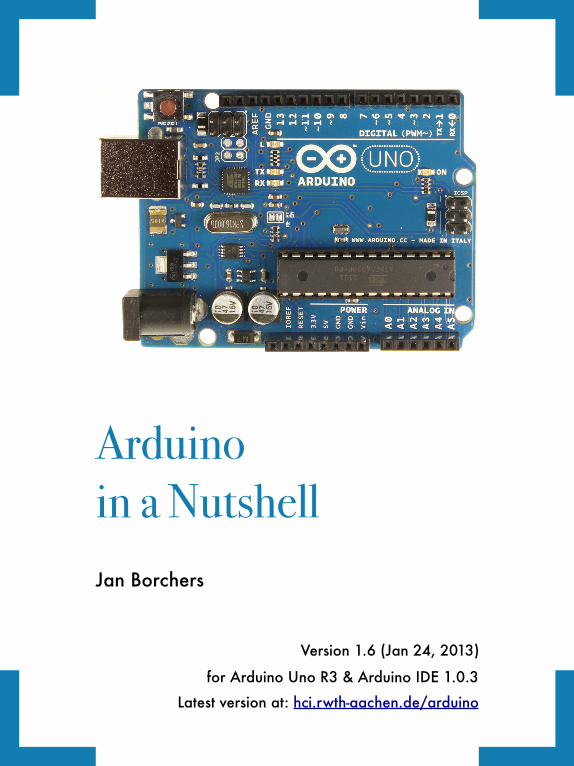
Arduinoin a NutshellJan Borchers
Version 1.6 (Jan 24, 2013)
for Arduino Uno R3 & Arduino IDE 1.0.3
Latest version at: hci.rwth-aachen.de/arduino

ACKNOWLEDGEMENTS
Thanks to Jeff and Drake for playing with the
Arduino last night, and almost completing our
plans for world domination through an army of
robots doing our bidding (insert finger wiggling
and evil laugh here). I wrote this booklet in
about four hours after getting home last night,
and illustrated it this morning. It closely follows
our adventures into Arduinoland.
The Arduino team continues to do an awesome job
providing this easy-to-use electronics platform, and all
schematics were created using the excellent software
from Fritzing.org. Jim Hollan at UCSD is a great host,
and my students back in Germany are bravely suffering
through (enjoying?) the time with me away on sabbatical.
This booklet is dedicated to Ina who is always
wonderfully supportive of her geek.
San Diego, Aug 9, 2012
For great feedback, thanks to the arduino-teachers,
Sketching In Hardware and i10 mailing lists, especially
CTP, David Mellis (Arduino), Gerald Ardito, Jonathan
Oxer (shieldlist), Linz Craig (SparkFun), Michael Shiloh,
Nick Ward, Patricia Shanahan, and Thorsten Karrer!
2 Arduino in a Nutshell

I. INTRODUCTION
The Arduino is a family of
microcontroller boards to simplify
electronic design, prototyping
and experimenting for artists,
hackers, hobbyists, but also many
professionals. Use it as brains for your robot, to build a
new digital music instrument, or to make your house plant
tweet you when it’s dry. Know a little programming, but
no electronics? This book will get you started quickly.
Arduinos (we use the standard Arduino Uno R3) contain
an ATmega microcontroller — that’s a complete computer
with CPU, RAM, Flash memory, and input/output pins,
all on a single chip. Unlike, say, a Raspberry Pi, it’s
designed to attach all kinds of sensors, LEDs, small
motors and speakers, servos, etc. directly to these pins,
which can read in or output digital or analog voltages
between 0 and 5 volts. The Arduino connects to your
computer via USB, where you program it in a simple
language (C/C++, similar to Java) inside the free
Arduino IDE by uploading your compiled code to the board.
Once programmed, the Arduino can run with the USB
link back to your computer, or stand-alone without it —
no keyboard or screen needed, just power.
Arduino in a Nutshell 3
II.!GETTING STARTED:! ! BLINK AN LED!
1.Get the MAKE Ultimate Micro-
controller Pack with an Arduino Uno
R3 from makershed.com or your local RadioShack
($149). Also get a standard USB A-B cable and a 9V
battery. Or, for just the parts we’ll use here, get the
Wish List at sparkfun.com/wish_lists/46366 ($64).
SparkFun’s Inventor’s Kit or Adafruit’s Experimenta-
tion Kit also have most parts we need, and more.
2. Download and install the Arduino IDE for Mac, Linux
or Windows from arduino.cc. Windows users also
need to install a driver .INF file, see the website.
3. Connect your board via USB, launch the Arduino
app, select Arduino Uno from the Tools:Board menu,
select the new serial port from Tools: Serial Port
(/dev/tty.usbmodem... on Macs), open the sketch
(program) File:Examples:01.Basics:Blink, and click the
➲ toolbar button to upload it to your board.
After some flickering, its tiny yellow LED should blink
regularly (1 second on, 1 second off). You’ve
programmed your first microcontroller! Change the
durations in delay() and upload to see the effect.
4 Arduino in a Nutshell
III. RUN WITHOUT A COMPUTER
1. Disconnect the USB cable from your board.
2. Put the 9V battery into the battery case (takes some
fiddling).
3. Plug the barrel plug from the battery case into the
round socket on the Arduino, and turn on the switch
on the battery case if it has one.
4. Your sketch starts running as soon as the board is
powered up, and the LED blinks, until you turn off
power — no computer needed! That’s a great way to
build small, autonomous systems around an Arduino.
The Arduino converts the 9V from the battery down to 5V
using a regulator on the board. You can also connect
anything from 7–12 volts DC to the barrel plug socket
(2.1 mm / 5.5 mm diameter, center positive), or stick
cables directly into the Vin and GND (Ground) pins to
power the board from 7–12 volts — great if you don’t
have a barrel plug on your power source.
Don’t attach a 5V power source directly to the +5V pin
though — it’s a voltage output pin only, and you may fry
your onboard regulator. Use the USB connector instead.
Arduino in a Nutshell 5
IV. CONNECT A BIG LED
1.Always disconnect or turn
off your power source before
you change your circuit to
avoid shorts. They may shut
down your USB port, or
worse.
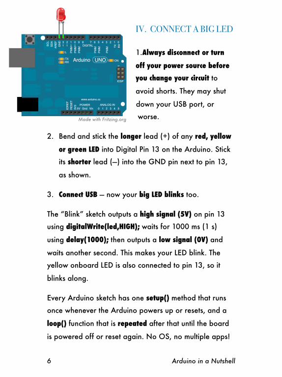
2. Bend and stick the longer lead (+) of any red, yellow
or green LED into Digital Pin 13 on the Arduino. Stick
its shorter lead (—) into the GND pin next to pin 13,
as shown.
3. Connect USB — now your big LED blinks too.
The “Blink” sketch outputs a high signal (5V) on pin 13
using digitalWrite(led,HIGH); waits for 1000 ms (1 s)
using delay(1000); then outputs a low signal (0V) and
waits another second. This makes your LED blink. The
yellow onboard LED is also connected to pin 13, so it
blinks along.
Every Arduino sketch has one setup() method that runs
once whenever the Arduino powers up or resets, and a
loop() function that is repeated after that until the board
is powered off or reset again. No OS, no multiple apps!
6 Arduino in a Nutshell
Made with Fritzing.org
V. ADD A RESISTOR
Connecting an LED directly to 5V and GND will usually
fry it because of too much current flowing through it. It
survived only because the Arduino can’t provide more
than 40 mA (milliamps) of current on each pin.
That’s still more than the 20 mA standard LEDs like and
need, however. LEDs also drop (consume) around 2V of
“forward” voltage (Vf). For precise values, google, e.g.,
“SparkFun red 5mm LED” (SparkFun sells great basic
components and documents them well). To limit the
current, add a resistor before or after the LED.
What’s the right resistor value? The Arduino pins provide
5V. 2V are dropped by the LED. That leaves 3V to drop
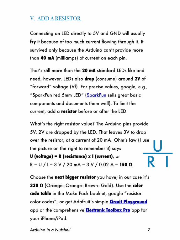
over the resistor, at a current of 20 mA. Ohm’s law (I use
the picture on the right to remember it) says
U (voltage) = R (resistance) x I (current), or
R = U / I = 3 V / 20 mA = 3 V / 0.02 A = 150 Ω.
Choose the next bigger resistor you have; in our case it’s
330 Ω (Orange–Orange–Brown–Gold). Use the color
code table in the Make Pack booklet, google “resistor
color codes”, or get Adafruit’s simple Circuit Playground
app or the comprehensive Electronic Toolbox Pro app for
your iPhone/iPad.
Arduino in a Nutshell 7
U R I

Disconnect USB. In the mini
solderless breadboard, each
vertical column of 5 holes is
connected inside the board.
Stick the LED, 330 Ω resistor
and jumper wires in as shown.
Current will now flow from
Arduino pin 13 through the
resistor and the LED to GND
when pin 13 is HIGH.
Connect USB. Your LED will glow slightly less bright than
before, but will last forever. The current is now around 3
V / 330 Ω = 9 mA. Current is the same everywhere in a
simple closed circuit without branches. So it doesn’t
matter if you put the resistor before or after the LED.
8 Arduino in a Nutshell
Made with Fritzing.org
Tip: Always use red wires for connections to 5V, black
wires for connections to GND, and other colors using a
schema you like. I use yellow wires for outputs to LEDs,
green wires for outputs to motors and servos, and blue
wires for sensor inputs. It’ll help avoid confusion, short-
circuits, and fried components. Trust me; I’ve been there.
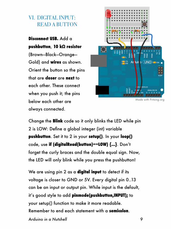
VI.!DIGITAL INPUT:! ! ! READ A BUTTON
Disconnect USB. Add a
pushbutton, 10 kΩ resistor
(Brown—Black—Orange—
Gold) and wires as shown.
Orient the button so the pins
that are closer are next to
each other. These connect
when you push it; the pins
below each other are
always connected.
Change the Blink code so it only blinks the LED while pin
2 is LOW: Define a global integer (int) variable
pushbutton. Set it to 2 in your setup(). In your loop()
code, use if (digitalRead(button)==LOW) {...}. Don’t
forget the curly braces and the double equal sign. Now,
the LED will only blink while you press the pushbutton!
We are using pin 2 as a digital input to detect if its
voltage is closer to GND or 5V. Every digital pin 0..13
can be an input or output pin. While input is the default,
it’s good style to add pinmode(pushbutton,INPUT); to
your setup() function to make it more readable.
Remember to end each statement with a semicolon.
Arduino in a Nutshell 9
Made with Fritzing.org

The 10 kΩ resistor is a pullup resistor. It provides a
defined voltage (5V) to pin 2 when the button switch is
open (it “pulls it up to 5V”). Otherwise pin 2 would be
connected to nothing, or “floating”, and pick up random
electromagnetic noise like an antenna, leading to
unpredictable HIGH/LOW values when you read it.
When you push the button, it pulls pin 2 low (connects it
to GND = 0V), and a small current flows through the
resistor and switch to GND. All 5V then “drop” across
the resistor. Arduino inputs themselves just “measure” the
voltage on their pins while consuming hardly any current.
VII. INTERNAL PULLUP RESISTORS
Remove the 10 kΩ pullup resistor from the board. Now
your LED may be blinking or not, since pin 2 is floating.
Change setup() to say pinMode(button, INPUT_PULLUP);
and upload. This connects an internal pullup resistor to
that pin inside the ATmega chip. It works like your
external pullup resistor, but you can simplify your circuit.
10 Arduino in a Nutshell
Tip: For help with any function, click on it, then select the
Help:Find In Reference menu. I also use the language
reference at arduino.cc/en/Reference a lot; more
tutorials are at arduino.cc/en/Tutorial/Foundations.
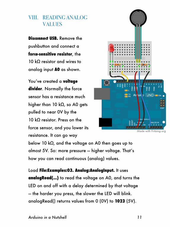
VIII.! READING ANALOG! ! ! ! ! VALUES
Disconnect USB. Remove the
pushbutton and connect a
force-sensitive resistor, the
10 kΩ resistor and wires to
analog input A0 as shown.
You’ve created a voltage
divider. Normally the force
sensor has a resistance much
higher than 10 kΩ, so A0 gets
pulled to near 0V by the
10 kΩ resistor. Press on the
force sensor, and you lower its
resistance. It can go way
below 10 kΩ, and the voltage on A0 then goes up to
almost 5V. So: more pressure — higher voltage. That’s
how you can read continuous (analog) values.
Load File:Examples:03. Analog:AnalogInput. It uses
analogRead(...) to read the voltage on A0, and turns the
LED on and off with a delay determined by that voltage
— the harder you press, the slower the LED will blink.
analogRead() returns values from 0 (0V) to 1023 (5V).
Arduino in a Nutshell 11
Made with Fritzing.org
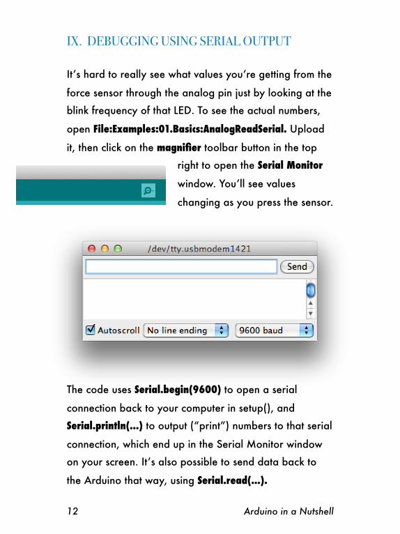
IX. DEBUGGING USING SERIAL OUTPUT
It’s hard to really see what values you’re getting from the
force sensor through the analog pin just by looking at the
blink frequency of that LED. To see the actual numbers,
open File:Examples:01.Basics:AnalogReadSerial. Upload
it, then click on the magnifier toolbar button in the top
right to open the Serial Monitor
window. You’ll see values
changing as you press the sensor.
The code uses Serial.begin(9600) to open a serial
connection back to your computer in setup(), and
Serial.println(...) to output (“print”) numbers to that serial
connection, which end up in the Serial Monitor window
on your screen. It’s also possible to send data back to
the Arduino that way, using Serial.read(...).
12 Arduino in a Nutshell

X.! ANALOG OUTPUT! ! ! AND PWM
Disconnect USB. Move the
yellow wire from pin 13 to pin
11. Pin 11 has a tilde (~) on
the board, which means it can
output analog values.
Change your loop() to control
the LED with analogWrite(...).
Analog values for output go
from 0 to 255, not 1023, so
divide the value from
analogRead(...) by 4 before
writing it to the LED pin.
Connect USB and upload your code. Now
you can control the brightness of your LED
by pressing on the force sensor.
Arduino uses Pulse-Width Modulation (PWM) to create
analog values — it’ll turn the output on (5V) and off (0V)
at 500 Hz, and increase the duty cycle (relative on-time)
of that square wave signal to represent higher analog
values. 500 Hz is too fast for the human eye, so the LED
looks like it’s always on, just more or less bright.
Arduino in a Nutshell 13
Made with Fritzing.org
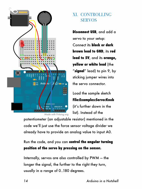
XI.! CONTROLLING! ! ! SERVOS
Disconnect USB, and add a
servo to your setup:
Connect its black or dark
brown lead to GND, its red
lead to 5V, and its orange,
yellow or white lead (the
“signal” lead) to pin 9, by
sticking jumper wires into
the servo connector.
Load the sample sketch
File:Examples:Servo:Knob
(it’s further down in the
list). Instead of the
potentiometer (an adjustable resistor) mentioned in the
code we’ll just use the force sensor voltage divider we
already have to provide an analog value to input A0.
Run the code, and you can control the angular turning
position of the servo by pressing on the sensor.
Internally, servos are also controlled by PWM — the
longer the signal, the further to the right they turn,
usually in a range of 0..180 degrees.
14 Arduino in a Nutshell
Made with Fritzing.org
However, the Servo library for Arduino takes care of all
this. Note the #import statement, the Servo object
declaration, and how the sample code then sends data to
the servo using angular values. You can easily declare,
create, and control two or more Servo objects this way —
essential for your robot!
Servos can take around 0.5–1s to reach their target
position. For a simple walking movement, you can just
send the maximum angle, wait, then send the minimum
angle, wait, and so on.
Arduino in a Nutshell 15
Tip: If you run out of 5V pins on the Arduino, bring 5V
over to a column on the breadboard, and connect things
from there (similar for GND). Use red and black wires to
keep your sanity! On larger breadboards like the large
one in the MAKE Pack, use the horizontal connector rows
(“rails”) along the top and bottom — put 5V only to the
top red rail, and GND only to the bottom blue rail, to
avoid plugging things into the wrong one.
XII. SHIELDS
Shields are PCBs that stack on top of the Arduino and
connect to all Arduino pins to add all kinds of hardware
features. There are shields to play MP3 files, for WiFi,
Bluetooth, Ethernet, Zigbee, MIDI, GPS, to log data,
drive big motors, etc. — shieldlist.org lists over 200!
Good shields are stackable — they have the same female
header pins as the Arduino on top.
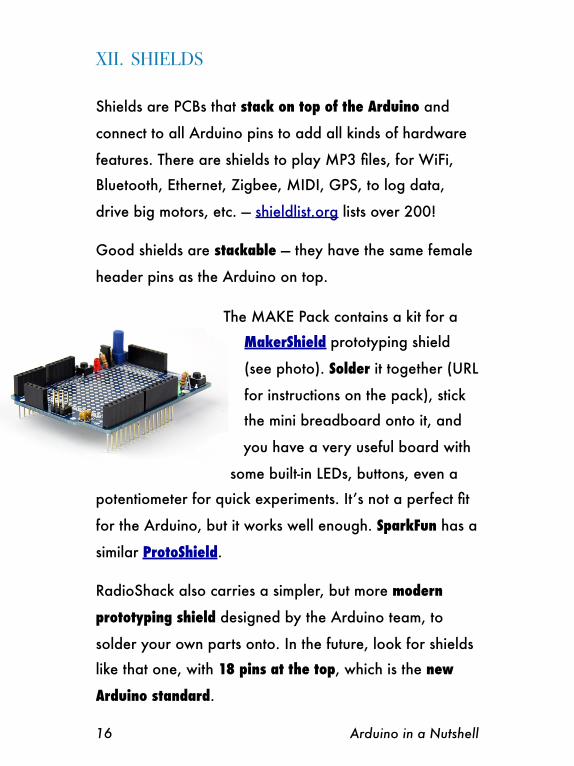
The MAKE Pack contains a kit for a
MakerShield prototyping shield
(see photo). Solder it together (URL
for instructions on the pack), stick
the mini breadboard onto it, and
you have a very useful board with
some built-in LEDs, buttons, even a
potentiometer for quick experiments. It’s not a perfect fit
for the Arduino, but it works well enough. SparkFun has a
similar ProtoShield.
RadioShack also carries a simpler, but more modern
prototyping shield designed by the Arduino team, to
solder your own parts onto. In the future, look for shields
like that one, with 18 pins at the top, which is the new
Arduino standard.
16 Arduino in a Nutshell
XIII. SOME POINTERS
To learn more about Arduino and build fun projects,
check out these resources:
arduino.cc is your first stop for help with the IDE, the
Arduino language reference, board specifications, new
boards and software versions, excellent mostly up-to-date
tutorials, and libraries for a lot of stuff you may want to
hook up to your Arduino.
Sparkfun.com has great components, shields, sensors,
breakout boards, etc. They support open-source
hardware and have all schematics online. Decent pricing,
great community. Epic Friday New Product Post videos.
Adafruit.com is smaller but similar, with great products,
learning resources and community support.
MAKE Magazine has an Arduino blog with great tutorial
videos at blog.makezine.com/arduino/ and lots of
Arduino projects at makeprojects.com/c/Arduino. The
paper magazine is also great fun, especially with kids.
RadioShack.com has all essential parts, a bit pricey, but
lets you check online if a part is available at your local
store around the corner — perfect for those last-minute
needs that always seem to come up.
Arduino in a Nutshell 17
Digikey.com, Mouser.com, and Farnell.com are
professional electronic component vendors. They carry
and have datasheets for everything, at the best prices if
you know what you’re looking for, but they are
overwhelming to beginners — try SparkFun, MakerShed,
Adafruit or RadioShack at first.
Fritzing.org has a nice free tool to document your
Arduino breadboard designs, and to design shields that
can then be made by submitting your files to an online
PCB maker. I used it for all the Arduino diagrams here.
In general, if you want to hook up X to an Arduino,
google “Arduino X” and you’re likely to find a solution. :)
Look for the above sites among the search results.
There are countless Arduino books out there; the gentlest
is probably Massimo Banzi’s Getting Started With
Arduino (he designed the Arduino board). The PDF is ten
bucks at the Makershed. Tom Igoe’s Making Things Talk
is excellent and beautifully designed, focusing on making
Arduinos and other electronic devices connect and share
information. Arduino Bots and Gadgets is interesting if
you want to build robots. However, all Arduino books
become outdated quickly because the Arduino boards
and IDE have changed slightly almost every year so far.
Look for a book edition that’s no older than a year.
18 Arduino in a Nutshell
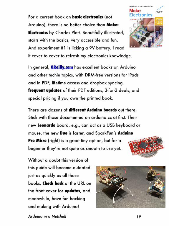
For a current book on basic electronics (not
Arduino), there is no better choice than Make:
Electronics by Charles Platt. Beautifully illustrated,
starts with the basics, very accessible and fun.
And experiment #1 is licking a 9V battery. I read
it cover to cover to refresh my electronics knowledge.
In general, OReilly.com has excellent books on Arduino
and other techie topics, with DRM-free versions for iPads
and in PDF, lifetime access and dropbox syncing,
frequent updates of their PDF editions, 3-for-2 deals, and
special pricing if you own the printed book.
There are dozens of different Arduino boards out there.
Stick with those documented on arduino.cc at first. Their
new Leonardo board, e.g., can act as a USB keyboard or
mouse, the new Due is faster, and SparkFun’s Arduino
Pro Micro (right) is a great tiny option, but for a
beginner they’re not quite as smooth to use yet.
Without a doubt this version of
this guide will become outdated
just as quickly as all those
books. Check back at the URL on
the front cover for updates, and
meanwhile, have fun hacking
and making with Arduino!
Arduino in a Nutshell 19
About the author
Jan Borchers is a professor of computer science and head of the Media Computing Group at RWTH Aachen University. He works in human-computer interaction, usability, and digital fabrication, and has taught Arduino to students and kids since 2008.
Feel free to use this booklet for yourself, with your friends, or in noncommercial classes. Instead of hosting a local copy, please link back to the URL on the cover so we can keep old versions from floating around. I’ll keep older versions of the booklet there for reference. Thanks!
This work is licensed under the Creative Commons Attribution-NonCommercial-NoDerivs 3.0 Unported License. To view a copy of this license, visit creativecommons.org/licenses/by-nc-nd/3.0/. For other uses, including commercial or derivative works, contact the author.
Version history
2013-01-24 (1.6): Added target audience, author info, premium headers on wishlist. Updated pushbutton declaration. Updated for IDE 1.0.2 & 1.0.3. Cosmetic corrections throughout.
2012-08-17 (1.5): Corrected button use in Ch.VI. Changed title page, tips layout, last page layout.
2012-08-15 (1.4): Added shieldlist.org.
2012-08-15 (1.3): Updated acknowledgements, Java reference, +5V pin, enabling pullups, page footers, layout. Added Creative Commons license terms.
2012-08-15 (1.2): Added: cropmarks, boldface in first chapters, Raspberry Pi, SparkFun wish list, other starter kits, Electronic Toolbox, Arduino Pro Micro, Make: Electronics cover, double-sided layout for binding. Edited: shields, O’Reilly, title, headings.
2012-08-12 (1.1): Added: missing sensor wire in ch. X+XI diagrams, Circuit Playground, different boards, version history. Fixed typos.
2012-08-09 (1.0): Initial release, see Acknowledgements.
20 Arduino in a Nutshell