
Arduino Friendly PSoC Shield - College of Engineering ... · The overall goal of this project was...
39
i Arduino Friendly PSoC Shield ECE 480 Senior Design Sponsor: Cypress Semiconductor Authors: Cecilia Acosta Brett Donlon Matt Durak Aaron Thompson Nathan Ward
Transcript of Arduino Friendly PSoC Shield - College of Engineering ... · The overall goal of this project was...

i
Arduino Friendly PSoC Shield
ECE 480 Senior Design
Sponsor:
Cypress Semiconductor
Authors:
Cecilia Acosta
Brett Donlon
Matt Durak
Aaron Thompson
Nathan Ward

ii
Executive Summary The overall goal of this project was to create an interface between the Cypress Programmable System
on Chip (PSoC) and Arduino daughterboards, known as shields. Specifically, the team focused on
interfacing the PSoC 5 First Touch kit with the Arduino Ethernet shield. The Ethernet Shield is a common
Arduino device which can connect to the internet and it includes a microSD card reader and writer. This
interface involved creating a custom printed circuit board (PCB) to connect the pins of the two devices.
It also required the team to write firmware code to handle the interaction and allow the PSoC to
communicate over the internet using the Ethernet Shield. The final software deliverable was packaged
in the development environment, PSoC Creator, as a reusable library component. This component
contained virtual hardware in a schematic layout to be programmed onto the PSoC as well as source
code. In order to demonstrate the functionality of this project, the team developed a number of
applications, including one to control an LED from a web browser, one to send sensor data to a web
service, and one to control the Arduino Motor Shield to show the product’s applicability to other
Arduino shields. The team completed all of the objectives, although it was unable to fully interface with
the SD card. This project should be useful to Cypress Semiconductor in expanding the PSoC market base
to existing Arduino developers as another low cost alternative to Arduino.

iii
Acknowledgement Team 1 would like to acknowledge the help and cooperation of several individuals who contributed to
the success of the project. Patrick Kane, the sponsor representative from Cypress, was of great help to
get the project started. He not only provided free hardware but he also gave the team invaluable advice
to get the project going. Dr. McGough, the faculty facilitator, pushed the team to go beyond what was
expected and to finish the project well before the due date. He encouraged each individual in the team
as well as the team as a whole to expand the goal of the project and deliver a more applicable and
marketable product.
Brian Wright greatly contributed to the success of the packaging of the product. With his knowledge,
willingness to help, and dedication the final product became much more appealing. Roxanne Peacock
greatly helped with the ordering of parts.
To all those listed above, we sincerely thank you for your cooperation. The success of the project had a
lot to do with your invaluable help.
iv
Table of Contents Executive Summary ....................................................................................................................................... ii
Acknowledgement ....................................................................................................................................... iii
Chapter 1: Introduction and Background ..................................................................................................... 1
Introduction .............................................................................................................................................. 1
Background ............................................................................................................................................... 2
Objectives ................................................................................................................................................. 3
Chapter 2: Exploring the Solution Space....................................................................................................... 4
Fast Diagram ............................................................................................................................................. 4
House of Quality ....................................................................................................................................... 5
Critical Customer Requirements (CCRs) .................................................................................................... 5
Conceptual Design Descriptions ............................................................................................................... 6
Ranking of Conceptual Designs ................................................................................................................. 7
Proposed Design Solution ......................................................................................................................... 9
Budget ..................................................................................................................................................... 11
Gantt Chart ............................................................................................................................................. 11
Chapter 3: Technical Description of Work Performed ................................................................................ 12
Hardware Design and Implementation ................................................................................................... 12
Software and Interface Design Requirements ........................................................................................ 15
Software Implementation ....................................................................................................................... 17
Problems Encountered ........................................................................................................................... 21
Chapter 4: Test Data with Proof of Functional Design................................................................................ 22
Final Prototype Description .................................................................................................................... 22
Project Applications ................................................................................................................................ 23
Test Methods .......................................................................................................................................... 23
Chapter 5: Final Cost, Schedule, Summary and Conclusions ...................................................................... 26
Summary ................................................................................................................................................. 26
Conclusion ............................................................................................................................................... 27
Appendix 1: Technical Roles, Responsibilities, and Work Accomplished ................................................... 28
Cecilia Acosta – Presentation Prep ......................................................................................................... 28
Brett Donlon – Lab Coordinator .............................................................................................................. 28
Matt Durak – Document Prep ................................................................................................................. 29

v
Aaron Thompson - Webmaster ............................................................................................................... 29
Nathan Ward - Manager ......................................................................................................................... 30
Appendix 2: Literature and Website References ........................................................................................ 31
Appendix 3: Detailed Technical Attachments ............................................................................................. 33
Source Code ............................................................................................................................................ 34
1
Chapter 1: Introduction and Background
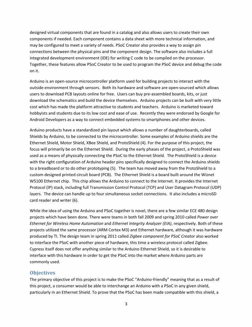
Introduction This project, sponsored by Cypress, was completed in order to make their Programmable System on
Chip (PSoC) be “Arduino-friendly”. This means that customers using Arduino products could be enticed
to purchase PSoC as an alternative to Arduino without encountering any technical difficulty when
interacting with the two components. Until recently the main audience using Arduino has been students
and hobbyists. In recent times, Google has specified Arduino as an Android development platform for
interacting with smartphones and sensors. By making PSoC “Arduino-friendly”, the chance of success in
capturing the intended audience is increased. The functionality required by the customer is a working
component in PSoC Creator and a piece of hardware which, together, will allow the PSoC to be used
with Arduino shields. The product should be easy to use for anyone familiar with PSoC Creator and
Arduino. There is an expectation that the product is to be very reliable and requires little to no
maintenance. The customers can expect a light weight, easy to carry, very accessible product at a low
cost with the desired functionality.
Elucidating more on the cost aspect of the project, students and hobbyists typically do not have access
to large sources of funding like that of a corporation. Therefore, it is desirable to implement more
solutions via code rather than hardware in order to keep costs low. Concerning the adaptability of the
design, the code of the web server should be similar to the way many hobbyists program the Arduino,
through the use of readable, modular functions and libraries.
The other customer of this product is Cypress Semiconductor. The needs of Cypress are primarily to
create a product with which the end user will be satisfied. This will hopefully help the company reach
out to Arduino developers in order to expand their customer base. The final delivery date for Cypress of
a working prototype is on December 9, 2011. This prototype demonstrates the final product.
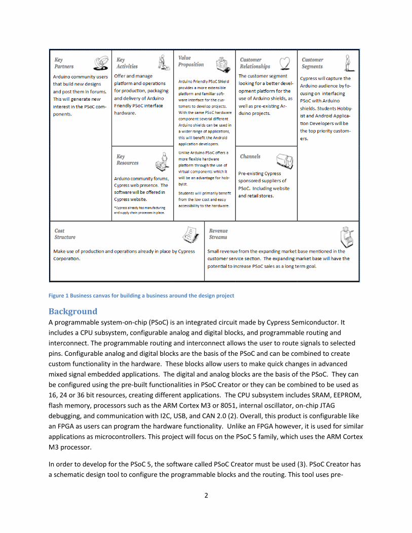
In the case of a business being generated from this product, the team built a business canvas shown in
Figure 1. The template and ideas for this canvas was acquired from Mr. Motter’s presentation (1). This
canvas only focuses on the originally intended customers, those being students, hobbyists and Android
platform developers. The business canvas allowed the team to document a potential business model for
the product.
2
Figure 1 Business canvas for building a business around the design project
Background A programmable system-on-chip (PSoC) is an integrated circuit made by Cypress Semiconductor. It
includes a CPU subsystem, configurable analog and digital blocks, and programmable routing and
interconnect. The programmable routing and interconnect allows the user to route signals to selected
pins. Configurable analog and digital blocks are the basis of the PSoC and can be combined to create
custom functionality in the hardware. These blocks allow users to make quick changes in advanced
mixed signal embedded applications. The digital and analog blocks are the basis of the PSoC. They can
be configured using the pre-built functionalities in PSoC Creator or they can be combined to be used as
16, 24 or 36 bit resources, creating different applications. The CPU subsystem includes SRAM, EEPROM,
flash memory, processors such as the ARM Cortex M3 or 8051, internal oscillator, on-chip JTAG
debugging, and communication with I2C, USB, and CAN 2.0 (2). Overall, this product is configurable like
an FPGA as users can program the hardware functionality. Unlike an FPGA however, it is used for similar
applications as microcontrollers. This project will focus on the PSoC 5 family, which uses the ARM Cortex
M3 processor.
In order to develop for the PSoC 5, the software called PSoC Creator must be used (3). PSoC Creator has
a schematic design tool to configure the programmable blocks and the routing. This tool uses pre-
3
designed virtual components that are found in a catalog and also allows users to create their own
components if needed. Each component contains a data sheet with more technical information, and
may be configured to meet a variety of needs. PSoC Creator also provides a way to assign pin
connections between the physical pins and the component design. The software also includes a full
integrated development environment (IDE) for writing C code to be compiled on the processor.
Together, these features allow PSoC Creator to be used to program the PSoC device and debug the code
on it.
Arduino is an open-source microcontroller platform used for building projects to interact with the
outside environment through sensors. Both its hardware and software are open-sourced which allows
users to download PCB layouts online for free. Users can buy pre-assembled boards, kits, or just
download the schematics and build the device themselves. Arduino projects can be built with very little
cost which has made the platform attractive to students and teachers. Arduino is marketed toward
hobbyists and students due to its low cost and ease of use. Recently they were endorsed by Google for
Android Developers as a way to connect embedded systems to smartphones and other devices.
Arduino products have a standardized pin layout which allows a number of daughterboards, called
Shields by Arduino, to be connected to the microcontroller. Some examples of Arduino shields are the
Ethernet Shield, Motor Shield, XBee Shield, and ProtoShield (4). For the purpose of this project, the
focus will primarily be on the Ethernet Shield. During the early phases of the project, a ProtoShield was
used as a means of physically connecting the PSoC to the Ethernet Shield. The ProtoShield is a device
with the right configuration of Arduino header pins specifically designed to connect the Arduino shields
to a breadboard or to do other prototyping (5). The team has moved away from the ProtoShield to a
custom designed printed circuit board (PCB). The Ethernet Shield is a board built around the Wiznet
W5100 Ethernet chip. This chip allows the Arduino to connect to the Internet. It provides the Internet
Protocol (IP) stack, including full Transmission Control Protocol (TCP) and User Datagram Protocol (UDP)
layers. The device can handle up to four simultaneous socket connections. It also includes a microSD
card reader and writer (6).
While the idea of using the Arduino and PSoC together is novel, there are a few similar ECE 480 design
projects which have been done. There were teams in both fall 2009 and spring 2010 called Power over
Ethernet for Wireless Home Automation and Ethernet Integrity Analyzer (EIA), respectively. Both of these
projects utilized the same processor (ARM Cortex M3) and Ethernet hardware, although it was hardware
produced by TI. The design team in spring 2011 called Zigbee component for PSoC Creator also worked
to interface the PSoC with another piece of hardware, this time a wireless protocol called Zigbee.
Cypress itself does not offer anything similar to the Arduino Ethernet Shield, so it is desirable to
interface with this hardware in order to get the PSoC into the market where Arduino parts are
commonly used.
Objectives The primary objective of this project is to make the PSoC “Arduino-friendly” meaning that as a result of
this project, a consumer would be able to interchange an Arduino with a PSoC in any given shield,
particularly in an Ethernet Shield. To prove that the PSoC has been made compatible with this shield, a

4
web server component will be created that will send and receive a message via the port on an Ethernet
Shield. Ideally, this will also utilize the SD card on the Ethernet Shield. This circuitry should be connected
to the PSoC via a custom printed circuit board which connects the proper pins. While this must work
with the Ethernet Shield, it is desirable to make this apply to all Arduino Shields. For that reason, the
team has developed a demonstration using the Motor Shield. In order to accomplish this task, the
“PSoC Creator” software had to be used to make electronic components that interface with the shield.
A required deliverable of this project was a reusable library component in PSoC Creator which could be
used by other developers with the Ethernet Shield. In total, the team was able to develop three
demonstration applications.
The first demo presented is switching and dimming lights remotely from a browser. This could easily be
translated to turning appliances on and off from a browser, without the need to be near the appliances
to use them. Another useful application built is the use of sensors with web alerts. For example, an
email alert is sent using the Pachube web service when some data captured by a sensor on the PSoC
changes. Finally, a demo utilizing the CapSense slider on the PSoC First Touch kit to control a DC motor
on the Arduino Motor shield showcases the universal nature of the design. It can be extended to
additional Arduino shields. The team believes that these applications will expand the customers of
Cypress not only by attracting Arduino users but by making the product much more marketable to users
outside of the originally expected clientele.
This project should serve as an example of the capabilities of PSoC with the Ethernet Shield. If it is easy
to get a project with an Arduino shield to function properly, the target audience will be eager to develop
with this platform. In order to appeal to this audience, the code should ideally serve as a general library
for reuse. If it is limited to a specific communication protocol it should be modular enough to have
additional functions added to it. This design constraint specifically applies to students and hobbyists who
all have varied interests and depend upon building their applications with adaptable platforms. If this
project can suitably work as well as an Arduino in producing a web server with the Ethernet shield, users
will come to view PSoC as a more powerful development platform than Arduino is viewed currently.
Chapter 2: Exploring the Solution Space
Fast Diagram A FAST Diagram, or Function Analysis System Technique Diagram, allows one to quickly visualize and
analyze the project. It also serves as a pattern of tasks that need to be accomplished in order to meet
the main goal the same as a “to do list” would. By reading the FAST diagram in Figure 16 (Appendix 3:
Detailed Technical Attachments), from left to right the question of “how is the task being done” is
answered. In the same token, the question of “why is the task being accomplished” is being answered
when the chart is read from right to left (7).
The entire project is represented in the FAST diagram. The diagram starts on the left with its main goal
of attracting Arduino users. This is being accomplished by emulating Arduino and demonstrating the
capabilities of the final product. The task of emulating Arduino is done by programming the PSoC and
5
connecting the shield while the capabilities of the product are demonstrated by creating a web server.
This process of dividing the tasks into subtasks continues until the project has been divided into its
smallest units. Breaking the project into these units represents a “divide and conquer” approach to
design.
The FAST diagram also serves to look at the smallest of tasks and follow the path back to distinguish why
each task is being done. As an example, by looking at the fabrication of the PCB this task was done in
order to connect the shields. Likewise, the shields are to be connected in order to emulate Arduino. As
mentioned before, emulating Arduino was one of the two key tasks of the main objective of attracting
Arduino users. This process allows the team to keep track of each step in the project while also keeping
the larger goal in sight, which is an extremely useful tool to use in the planning and development of the
project.
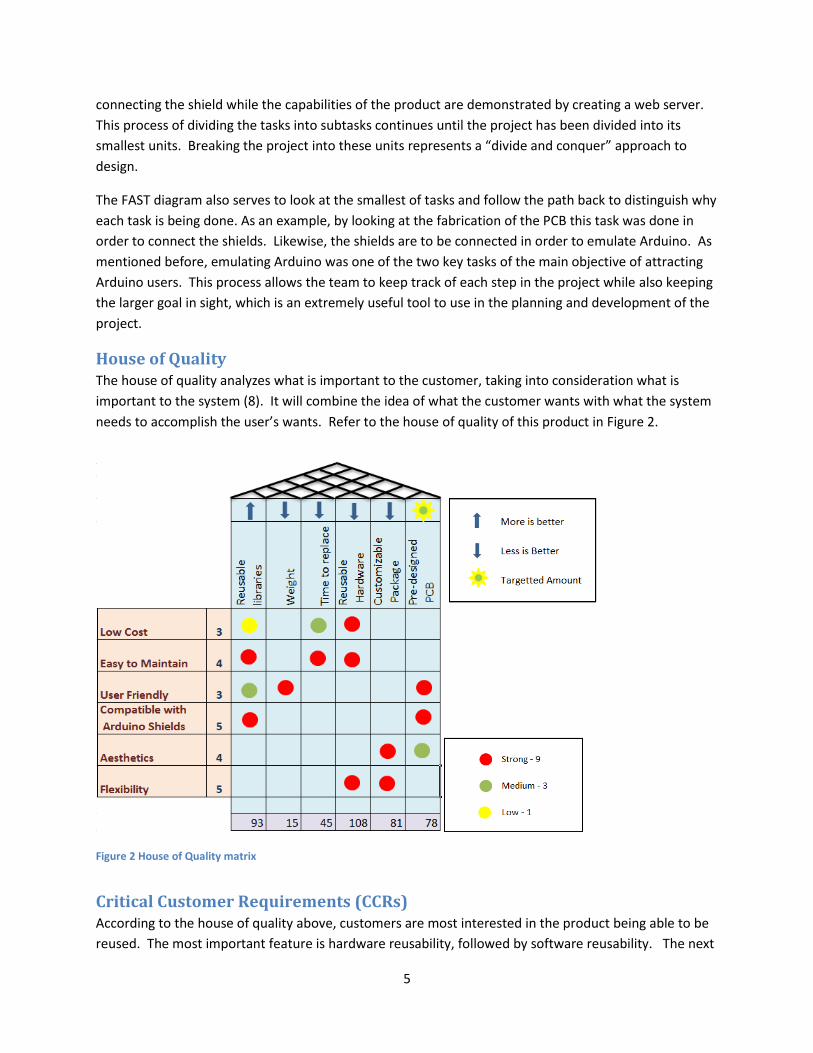
House of Quality The house of quality analyzes what is important to the customer, taking into consideration what is
important to the system (8). It will combine the idea of what the customer wants with what the system
needs to accomplish the user’s wants. Refer to the house of quality of this product in Figure 2.
Figure 2 House of Quality matrix
Critical Customer Requirements (CCRs) According to the house of quality above, customers are most interested in the product being able to be
reused. The most important feature is hardware reusability, followed by software reusability. The next

6
important feature is for the product to have a customizable package and a pre-designed PCB. The least
important components of the product are the weight of the final product and the time it takes for the
system to be replaced.
Conceptual Design Descriptions In order to satisfy the constraints requested by the customer, several potential designs have been
proposed. These designs can be divided into both hardware and software aspects of the final product.
The hardware design aspect involves figuring out how to connect the physical hardware. One such
design involves stacking of three commercially available components: the PSoC on the bottom, then the
ProtoShield, and then the Ethernet Shield. The design involves some wiring and soldering in order to
adapt the PSoC to the ProtoShield and correctly connect the pins from the PSoC to the Arduino shield
headers. The electronic connections between the PSoC and the Ethernet Shield will use the general
purpose pins of the PSoC which can be configured in software using PSoC creator. A second design
involves developing a custom PCB rather than building off of the ProtoShield. This design can either be
physically laid out as the ProtoShield in a stacked configuration, or it can be arranged so that the two
components are connected side-by-side. The physical PCB can also optionally have some sort of
packaging, enclosure, or stand in order to make it aesthetically pleasing and user friendly.
Concerning the software aspect of the project, there are two proposed solutions for the device
firmware. The firmware code may be written completely from scratch. This would involve a completely
custom approach and careful testing by the team in order to ensure that the PSoC interfaces with the
Arduino Ethernet Shield. The other design involves using parts of the existing open-source Arduino
library code and modifying it to work with the PSoC. This design would maximize the reuse of the
existing code, and be based upon a well-tested software library.
One final aspect of the software design involves the actual application code. This demonstration code
must prove that the PSoC to Ethernet Shield interface is working but it should also show the usefulness
of this product as a whole. Several solutions are proposed by the team as possible demos, although only
a small number will be practical in the time allotted. The first solution is to build upon the
TinyWebServer library found online at github (9). An example project for Arduino utilizes this library to
build a web application running off of the Arduino which can turn an LED on or off from a browser on a
computer or other device (10). The team has proposed expanding upon that demo to add other
capabilities. A different demo would be one which uses the TinyWebServer library to send static html,
javascript, and cascading style sheet (CSS) files over HTTP as an actual web server running on the PSoC.
The library from TinyWebServer handles routing an HTTP request to a function and the application
written by the team would have to handle finding a specific file to send from the SD card to the HTTP
client. Another solution is to port the library application known as PHP 4 Arduino (11) to the PSoC. This
would allow the team to build an application which can insert sensor data into an html web page just
like a simple version of the PHP programming language on desktop servers (12). The web page would
then be served over HTTP from the PSoC. A fourth demo involves taking some sensor data from the
PSoC and sending an alert via Twitter or email to a user so that they may be notified of some change.
This would require interfacing with the Twitter API or and SMTP server for email. Another demo
solution would be to log sensor data to a web service such as Pachube (13). This demo could send the

7
data at periodic intervals and use the Pachube service to interact with other services such as Twitter. A
sixth demo application would show how the PSoC and Ethernet Shield could interact with Android by
writing code to interface the devices with socket programming. This would help show that PSoC is also a
viable solution for Android development. A different application would be one which uses the PSoC to
control a motor with the Arduino Motor Shield. This demo would show that the product developed
works with more than one Arduino Shield.
Ranking of Conceptual Designs In the feasibility matrix, several different conceptual solutions are compared, organized into three
separate categories: hardware solutions, software solutions, and software demos. The various potential
solutions presented here are rated by five different criteria deemed to be important by Cypress and by
the team’s own analysis. Table 1 shows the feasibility matrix for the hardware portion of the design.
Table 2 compares the software solutions. Finally, Table 3 shows the feasibility rankings of the various
demo applications. All of the designs referenced in these tables are numbered with the description
listed in Table 4.
Engineering Criteria
Imp
orta
nce
Possible Hardware Solutions
H1 H2 H3 H4 H5
Cost 2 9 3 1 3 1
Difficulty to Develop 2 9 3 1 3 1
User Friendly 5 1 3 9 9 9
Aesthetics 4 1 3 9 3 9
Impression 4 1 3 3 3 9
Totals 49 51 97 81 121
Normalized Totals: 4.083333 4.25 8.083333 6.75 10.08333
9 = Best, 1 = Worst Table 1 Feasibility matrix for hardware solution
Engineering Criteria
Imp
orta
nce
Possible Software Solutions
S1 S2
Cost 2 N/A N/A
Difficulty to Develop 2 1 3
User Friendly 5 3 9
Aesthetics 4 N/A N/A
Impression 4 N/A N/A
Totals 17 51
Normalized Totals: 1.416666667 4.25

8
9 = Best, 1 = Worst Table 2 Feasibility matrix for software solution
Engineering Criteria
Imp
orta
nce
Possible Software Demos
D1 D2 D3 D4 D5 D6 D7
Cost 2 N/A N/A N/A N/A N/A N/A N/A
Difficulty to Develop 2 9 9 1 1 9 1 9
User Friendly 5 3 9 9 3 3 3 3
Aesthetics 4 N/A N/A N/A N/A N/A N/A N/A
Impression 4 3 3 9 3 3 9 9
Totals 45 75 83 29 45 53 69
Normalized Totals: 7.5 12.5 13.83 4.833 7.5 8.833 11.5
9 = Best, 1 = Worst Table 3 Feasibility matrix for software demos
Solution Number Brief Description H1 PSoC and Arduino Shield connected via ProtoShield H2 Custom PCB in a stacked arrangement H3 Custom PCB in a stacked arrangement with an enclosure H4 Custom PCB in side-by-side arrangement H5 Custom PCB in side-by-side arrangement with an enclosure S1 Custom firmware library code S2 Modifications based on existing Arduino library code and firmware D1 LED Demo using TinyWebServer D2 Static web file server over HTTP using TinyWebServer D3 Dynamic web server using PHP 4 Arduino D4 Twitter or email client for sensor data alerts D5 Logging sensor data to Pachube D6 Interfacing with Android D7 Motor Shield Demonstration Table 4 Solution descriptions for feasibility matrices
From this data the two categories, “cost” and “difficulty to develop”, were assigned the lowest weight
among all of the criteria. Cost is not as important to this project due to the budget allotted and the
components provided by Cypress. The PSoC utilizes virtual components to achieve much of its hardware
functionality, such as for the implementation of the SPI. Because this project does not require the
purchasing of expensive hardware components, the budget can be used for things that might not have
been a priority otherwise, such as a custom PCB and protective packaging. Also this project is a proof of
concept that the PSoC can be “Arduino-Friendly”, the costs do not need to be optimized for mass-
production as of yet. The “difficulty to develop” criterion is not relatively important because in most
cases, a development path that yields more impressive results may justify the extra work inherent in
that path. The team has decided to take risks to yield the greatest results.

9
The other criteria that were deemed important were “User Friendly”, “Aesthetics”, and “Impression”.
Making a user friendly device is by far the most important aspect of this project. Since this project
should appeal to students, hobbyists, and the ever-growing Arduino market, the goal is to make
development on PSoC as easy as development on the Arduino. The implications of this important
criterion will be discussed later. “Aesthetics” and “Impression” are also important aspects of the project
which deal with the general feelings a consumer will have upon first observing the product. The design
team aims to impress potential users upon viewing the completed system, encouraging them to use the
PSoC for their own projects.
Proposed Design Solution The final design decision follows the summation of the criteria in the feasibility matrix. Concerning the
hardware category, due to the fact that the weights of “cost” and “difficulty to design” were relatively
small, the final design will have a custom PCB and a protective enclosure. The PCB will not follow the
same physical layout as the ProtoShield, rather it will be wide enough to accommodate the PSoC and the
Ethernet Shield side-by-side. This will allow users to access and see all of the connections and
informational LEDs on both the PSoC and the Ethernet Shield, and will allow for easier mounting within
the packaging.
Figure 3 Physical design consists of a custom PCB which secures and connects the PSoC and Ethernet Shield.
Concerning the software category, the code will directly port the pre-made Arduino libraries (Figure 4)
for Ethernet and SD card interaction. Choosing this method will accomplish two things, firstly it will be
easier for users to develop because the code is already well-tested on the Arduino platform using a
similar compiler to the one available in PSoC Creator. The task at hand is to modify the lower level
hardware function calls and hardware registers specific to Arduino. Secondly, by porting already existing
Arduino code, to the application programming interface (API) for the end user will be the same as
Arduino. This will allow Arduino developers to easily transition to the PSoC platform. There are certain
Custom PCB
Ethern
et Shield
PSo
C

10
important changes that still need to be made to get the existing Arduino libraries to work, but the
software is already well designed at a higher level.
As for the software demos, the system should perform the basic tasks required by Cypress, namely some
form of communication between the PSoC and another device on the network using the Ethernet Shield.
It should also demonstrate the capability of the SD card reading and writing. However, it is also
desirable to make more complex demos that are beyond the scope of the present task in order to truly
entice the existing Arduino developers to move to the PSoC platform. The primary constraint on such
demonstrations, however, is development time in addition to the time allotted to making the firmware
work. The team has decided to implement the LED demo using TinyWebServer, the Pachube data
collection demo, and a demonstration using the CapSense slider with the Motor Shield. These three
demos together will demonstrate all required capabilities of the device and show its usefulness.
As a part of the feasibility study, the team has eliminated the direct Twitter or email alert demo in favor
of the Pachube web service acting as a middle layer. The direct interface to Twitter is impractical and
may be impossible. Twitter requires Secure Sockets Layer (SSL) authentication for its applications (14).
The SSL authentication is well beyond the capabilities of the current Ethernet Shield and the PSoC. It
would require a large amount of hashing and encryption which is not reasonable in this system. The
common solution to this problem is to communicate with a middle server requiring less security in order
to make the communication from the embedded system as simple as possible. Similarly, all worthwhile
email servers use SSL authentication for logging in. While the PSoC with Ethernet Shield could
communicate with a test SMTP server with no real security, this is not a reasonable email system and
therefore not really a practical email demonstration. Due to these concerns, the team decided to use
the Pachube service rather than communicating directly with Twitter or email.
Figure 4 The higher level application code for demos depends on the libraries ported from Arduino. The main task in coding this project arises from replacing resource calls to Arduino hardware with calls to the hardware provided by the PSoC, mainly the SPI hardware. Once this has been done, the higher level code largely stays the same because both platforms use C++.
Interface with Hardware
Arduino Core Library
SPI Library
Ethernet Library SD Library
C++ Application Code
Ethernet Hardware Library SD Hardware Library
11
Many have developed new shields and demo applications for Arduino. Never has there been a new
board or development environment for programming these shields. Design Team 1’s project scope
changes this and looks to introduce a new development environment with expanded capabilities in the
form of PSoC. This design project also extends the use of the PSoC as well. The Arduino Friendly PSoC
Shield allows the PSoC to interface with devices that would previously not be interfaced with i.e.
Arduino shields. This project will be successful due to the extended capabilities of both platforms and
therefore the extended amount of users that will be interested in using the project. The readily available
Arduino libraries and the versatility of PSoC Creator allow for this design to come into fruition. The
hardware solution and the demo applications provided by Design Team 1 prove that the design is
successful.
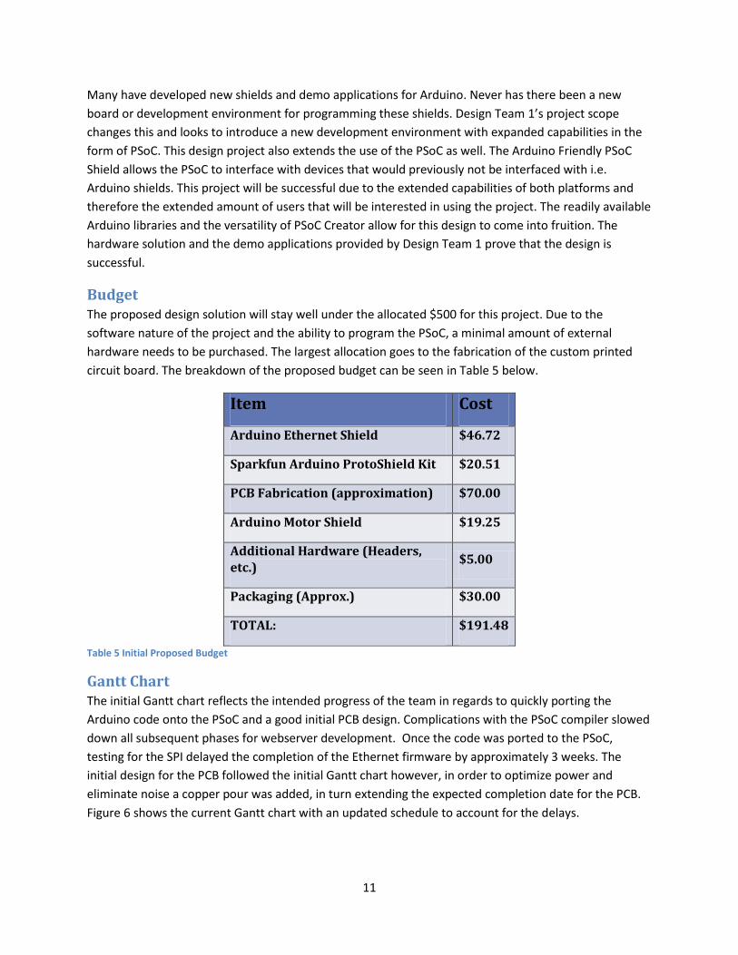
Budget The proposed design solution will stay well under the allocated $500 for this project. Due to the
software nature of the project and the ability to program the PSoC, a minimal amount of external
hardware needs to be purchased. The largest allocation goes to the fabrication of the custom printed
circuit board. The breakdown of the proposed budget can be seen in Table 5 below.
Item Cost
Arduino Ethernet Shield $46.72
Sparkfun Arduino ProtoShield Kit $20.51
PCB Fabrication (approximation) $70.00
Arduino Motor Shield $19.25
Additional Hardware (Headers, etc.)
$5.00
Packaging (Approx.) $30.00
TOTAL: $191.48
Table 5 Initial Proposed Budget
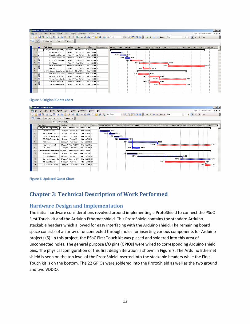
Gantt Chart The initial Gantt chart reflects the intended progress of the team in regards to quickly porting the
Arduino code onto the PSoC and a good initial PCB design. Complications with the PSoC compiler slowed
down all subsequent phases for webserver development. Once the code was ported to the PSoC,
testing for the SPI delayed the completion of the Ethernet firmware by approximately 3 weeks. The
initial design for the PCB followed the initial Gantt chart however, in order to optimize power and
eliminate noise a copper pour was added, in turn extending the expected completion date for the PCB.
Figure 6 shows the current Gantt chart with an updated schedule to account for the delays.
12
Figure 5 Original Gantt Chart
Figure 6 Updated Gantt Chart
Chapter 3: Technical Description of Work Performed
Hardware Design and Implementation The initial hardware considerations revolved around implementing a ProtoShield to connect the PSoC
First Touch kit and the Arduino Ethernet shield. This ProtoShield contains the standard Arduino
stackable headers which allowed for easy interfacing with the Arduino shield. The remaining board
space consists of an array of unconnected through holes for inserting various components for Arduino
projects (5). In this project, the PSoC First Touch kit was placed and soldered into this area of
unconnected holes. The general purpose I/O pins (GPIOs) were wired to corresponding Arduino shield
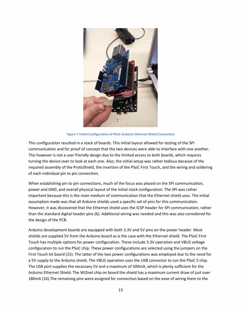
pins. The physical configuration of this first design iteration is shown in Figure 7. The Arduino Ethernet
shield is seen on the top level of the ProtoShield inserted into the stackable headers while the First
Touch kit is on the bottom. The 22 GPIOs were soldered into the ProtoShield as well as the two ground
and two VDDIO.
13
Figure 7 Initial Configuration of PSoC-Arduino Ethernet Shield Connection
This configuration resulted in a stack of boards. This initial layout allowed for testing of the SPI
communication and for proof of concept that the two devices were able to interface with one another.
This however is not a user friendly design due to the limited access to both boards, which requires
turning the device over to look at each one. Also, the initial setup was rather tedious because of the
required assembly of the ProtoShield, the insertion of the PSoC First Touch, and the wiring and soldering
of each individual pin to pin connection.
When establishing pin to pin connections, much of the focus was placed on the SPI communication,
power and GND, and overall physical layout of the initial stack configuration. The SPI was rather
important because this is the main medium of communication that the Ethernet shield uses. The initial
assumption made was that all Arduino shields used a specific set of pins for this communication.
However, it was discovered that the Ethernet shield uses the ICSP header for SPI communication, rather
than the standard digital header pins (6). Additional wiring was needed and this was also considered for
the design of the PCB.
Arduino development boards are equipped with both 3.3V and 5V pins on the power header. Most
shields are supplied 5V from the Arduino board as is the case with the Ethernet shield. The PSoC First
Touch has multiple options for power configuration. These include 3.3V operation and VBUS voltage
configuration to run the PSoC chip. These power configurations are selected using the jumpers on the
First Touch kit board (15). The latter of the two power configurations was employed due to the need for
a 5V supply to the Arduino shield. The VBUS operation uses the USB connector to run the PSoC 5 chip.
The USB port supplies the necessary 5V and a maximum of 500mA, which is plenty sufficient for the
Arduino Ethernet Shield. The WIZnet chip on board the shield has a maximum current draw of just over
180mA (16).The remaining pins were assigned for connection based on the ease of wiring them to the
14
PSoC First Touch kit while in the stack configuration. The ability to program the function of these pins in
PSoC Creator based on the need of the application allowed for this approach.
The design specifications presented to Design Team 1 did not include the design and fabrication of a
custom PCB. However, the team expressed the importance of incorporating this into the final
deliverable. The ease of use and ability to access both boards, especially the First Touch kit because of
the sensors it is equipped with, drove the team to design the PCB. The PCB allows the user to simply
plug each device into the board and begin programming their application. The design solution described
previously of having a side by side layout with headers for inserting each device was completed using
the DipTrace software. The components and patterns were created first, followed by the schematic
which used the pin connections established in the initial stack configuration. Finally, the layout was
completed and sent off for professional fabrication by Advanced Circuits (see Appendix 3: Detailed
Technical Attachments for figures pertaining to PCB Layout and pin to pin connections between the First
Touch kit and Arduino Ethernet shield). The completion of this task improved the overall aesthetic of the
final design as well as usability for the students and hobbyists that this project was aimed at.
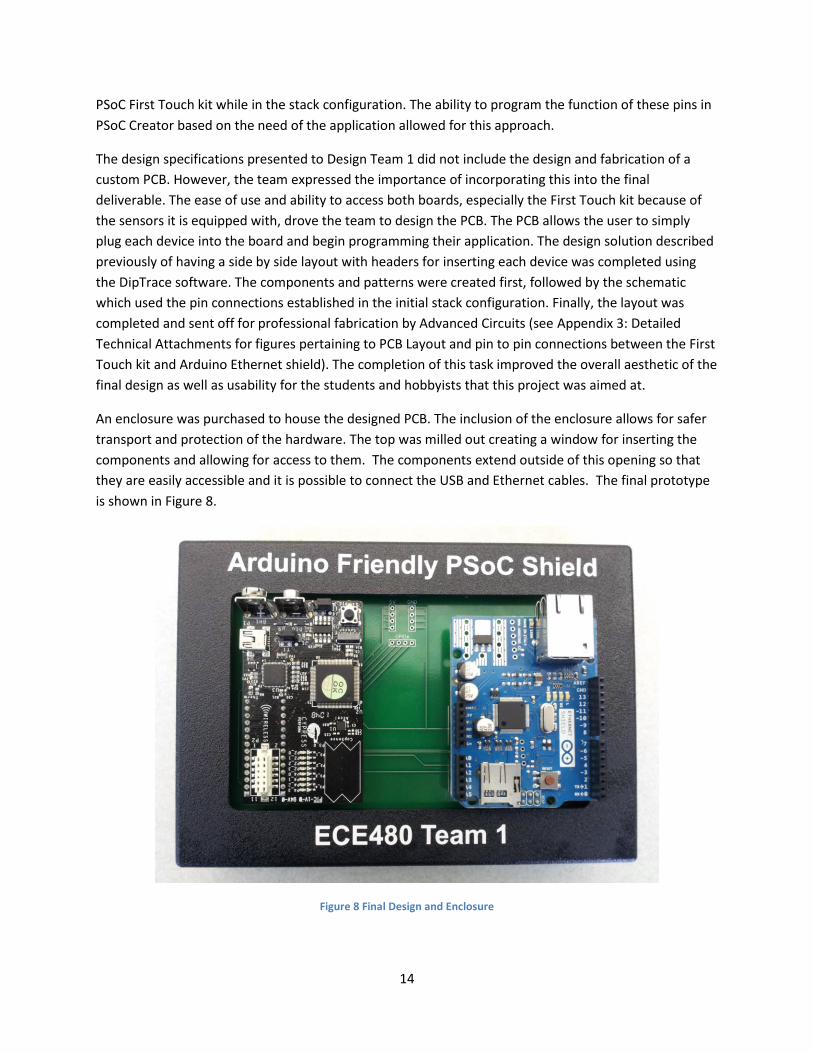
An enclosure was purchased to house the designed PCB. The inclusion of the enclosure allows for safer
transport and protection of the hardware. The top was milled out creating a window for inserting the
components and allowing for access to them. The components extend outside of this opening so that
they are easily accessible and it is possible to connect the USB and Ethernet cables. The final prototype
is shown in Figure 8.
Figure 8 Final Design and Enclosure

15
Software and Interface Design Requirements The primary requirements for the software in this design were to utilize the PSoC Creator environment,
to make PSoC firmware to interface with Arduino hardware, to develop a demonstration application,
and to develop a reusable library component in PSoC Creator. The first two requirements were fixed as
part of the project description. The latter requirements were the two project deliverables. An
additional requirement defined by the team was to make the code as similar to the Arduino application
programming interface (API) as possible, in order to ease the transition from Arduino to PSoC.
Using PSoC Creator as the development environment was a requirement in order to program the PSoC.
PSoC Creator provides the virtual component definition and configurations which make configuring the
system on chip simple for the user. By adding virtual components in the schematic layout editor in PSoC
Creator, a user application will automatically get a generated API to use that component. This is a
crucial part of the development workflow for the PSoC, so the current project had to use this
environment. It would be much more difficult to program the PSoC without PSoC Creator. This did
however place a restriction on the compiler tools which could be used. PSoC Creator supports the open
source GNU Compiler Collection (GCC) as well as the commercial Keil C compiler.
Building firmware to interface with the Arduino hardware required writing code for the PSoC which
could communicate with Arduino shields. Specifically, the Ethernet Shield firmware was the focus of this
project. The firmware needed to utilize serial peripheral interface (SPI) communication on external pins
in order to work with the Ethernet Shield and many other Arduino shields. This involved building an SPI
master module in PSoC Creator, which includes the SPI functionality. Software had to be written to
transmit data using this virtual component on the PSoC. Fortunately, the Cypress PSoC SPI virtual
component includes a full API for SPI communication. Therefore, the requirements of the firmware were
to send and receive the proper bytes of data in order to interface with the specific shield.
In order to understand the Ethernet Shield communication, it is important to be familiar with the SPI
protocol. SPI is a common way for embedded devices to communicate. It has one device in master
mode, which controls one or more slave devices, such as the Ethernet controller and SD card in this
project. Each SPI device has a pin for the “SPI Clock” (SCK), “Master In Slave Out” (MISO), “Master Out
Slave In” (MOSI), and “Slave Select” (SS). The master device will send an SCK signal to all slaves so that
the communication is syncrhronous. A slave device is only active if its SS input is set to logic low. This
allows the master device to selectively communicate with one or more devices, as is the case of the
shared SPI bus in the Ethernet Shield. During an SPI transmission, the master sends a sequence of bits
on the clock edge and the slave sends a sequence of bits back on the same clock edge. This
simultaneous transfer means that the protocol is full-duplex as it sends and receives a byte at a time.
The clock edge can be either the positive or negative edge depending on the phase setting. Also, it may
be either high or low as an idle state depending on the clock polarity setting. The phase and polarity
settings together are defined based on the SPI mode used by the device. Mode 0 has a low clock signal
in idle and the data transfers on the rising edge. Mode 1 differs from Mode 0 only in that it uses the
falling edge. Likewise Modes 2 and 3 operate as Modes 0 and 1 respectively, but with a high clock signal
in idle. SPI can also be configured to either send the most significant or least significant bit first (17).
For the purpose of this project, the Ethernet Shield operates in either Mode 0 or 3.
16
The other task in interfacing with the Ethernet Shield involves using the microSD card on the shield. This
is controlled over the same SPI bus as the Ethernet controller and thus uses a different SS signal. Secure
Digital (SD) cards have a standard developed by the SD Association. The communication follows a
procedure of initializing the card and then sending a series of commands and waiting for responses.
Each command is sent with a one byte code, a two to five byte argument, and a cyclic redundancy check
(CRC) byte. The CRC byte is ignored by the SD controller once it is initialized and running in SPI mode.
After all the bytes are sent, the master SPI device can send a byte of all 1’s (FF) and get the response
code as one to five bytes, depending on the command issued. This is the basis of all communication for
reading from and writing to the card (18).
The bulk of the firmware to talk to the Ethernet Shield involves sending byte sequences to the WIZnet
W5100 on the shield and receiving responses. The format of this communication over SPI involves a one
byte opcode, two byte address, and one byte to write or a one byte response from the shield. The op
codes may be either a read (0x0F) or a write (0xF0). The expected response bytes from the SPI slave on
the WIZnet are a sequence of 0, 1, 2, and either 3 or the data to read. All communication with the
WIZnet involves reading from or writing to specific registers. The hardware itself handles the Internet
Protocol (IP) and Transmission Control Protocol (TCP) as well as User Datagram Protocol (UDP). It can
handle up to four simultaneous socket connections. Interface code must send data to initialize the
WIZnet microcontroller and then it can use the WIZnet registers to write socket code which will be
handled by the Ethernet Shield (16).
The requirement for a demo application was to simply show that the PSoC could interface with the
Ethernet Shield by sending and receiving data over the Internet and ideally reading from and writing to
the SD card on the shield. The team built upon this requirement and defined a successful application as
one that can demonstrate the usefulness of the PSoC to Arduino interface in practice. This was further
elaborated to focus on home automation and sensors as a part of the “Internet of Things”. “The Internet
of Things” is a larger movement toward adding objects to the Internet in order to track data associated
with them and to control them (19). It is a broad topic, but the application presented in this project
provides a means of connecting some of those objects to the existing Internet in order to collect sensor
data and to control the objects. The requirement has also been further extended to demonstrate a
second shield, in this case the Motor Shield.
Developing a PSoC library component is a way to make this software reusable. PSoC Creator allows
developers to package designs created in the schematic layout editor into reusable symbols. These
symbols can then be used in other projects the same way as the primitive components. The reusable
component can include its schematic as well as a software API which will be included in the user
application code. In the case of this project, this would allow a user to write an application using an
Arduino Shield by including the pre-built component.
The team determined that the additional requirement of keeping the code compatible with the Arduino
API would be most beneficial to the goals of this project. In order to attract the current Arduino market
of students, hobbyists, and Android developers, this PSoC component should be a smooth transition.

17
Ideally, one can take an existing Arduino project, make some minor changes to the code, and paste it
into the PSoC project. This code should then compile and run on the PSoC.
Software Implementation As outlined in the proposed design solution, the software implementation is a partial port of the open
source Arduino library code (20). Specifically, the code for some of the base classes and the Ethernet
and SD card libraries are used. The code is used with as few modifications as possible. In order to make
the code work, anything specific to the Arduino hardware or its registers had to be removed. Also,
anything using standard libraries from AVR for its ATMega had to be removed. These removed
implementations needed to be replaced with the Cypress PSoC implementations by using the code from
the generated API’s.
The primary hardware implementation which was replaced from the Arduino library was the SPI
communication. The primary functionality in SPI involves sending a byte of data from the SPI master
and receiving a byte of data back from the slave device, which was the Ethernet Shield in this case. The
original Arduino code to transfer a byte is shown in Listing 1. This code puts a byte of data in the SPI data
register. It then waits for the SPI status register to have the SPI “finished” bit set. At that point, it
returns the contents of the SPI data register which holds the received data. The equivalent SPI transfer
function for the PSoC is found in Listing 2. Similarly, this writes a byte of data to the SPI, waits for the
SPI to go into a “done” state, and returns the contents of the received buffer. This function simply calls
through to the PSoC Creator generated SPI API file which wraps the actual registers into C functions.
Listing 1 Arduino SPI transfer method
Listing 2 PSoC implementation of the SPI transfer method
Some other parts of the SPI implementation needed to be replaced as well. The initialization routine
from Arduino involved setting the data direction of various pins and initializing certain status registers.
That code is replaced for the PSoC by a simple API call to a “start” method. Also, in order to
communicate with both the Ethernet controller and the SD card controller, two difference SPI slave
devices are present on the same bus with a different slave select signal. The slave select is set to logic
byte SPIClass::transfer(byte _data) {
SPDR = _data;
while (!(SPSR & _BV(SPIF)))
;
return SPDR;
}
byte SPIClass::transfer(byte _data) {
SPIM_1_WriteTxData(_data);
while (!(SPIM_1_ReadTxStatus() & SPIM_1_STS_SPI_DONE));
while (SPIM_1_GetRxBufferSize() == 0);
return SPIM_1_ReadRxData();
}

18
low during an SPI transmission and set to high otherwise. This allows the two parts of the shield to work
by turning on only one at a time. The Arduino implementation used its own pin registers which had to
be replaced by the PSoC generated methods to write to the given pins.
Porting the Arduino library by itself is not enough to build a working Arduino “friendly” PSoC. It is also
required to build the necessary virtual components in PSoC Creator. In order to use the Ethernet Shield,
the bare minimum required components are an SPI master component and two digital pins for the slave
selects. The layout of this component is shown in Figure 9. The connections are mostly straight
forward, with some exceptions. The two slave select pins are not connected to the SPI component.
Instead, the existing Arduino code has functions in place to set the corresponding slave select to “high”
or “low” accordingly. The remaining pins use the SPI module as it is implemented.
Figure 9 PSoC Creator SPI Master component for the Ethernet Shield
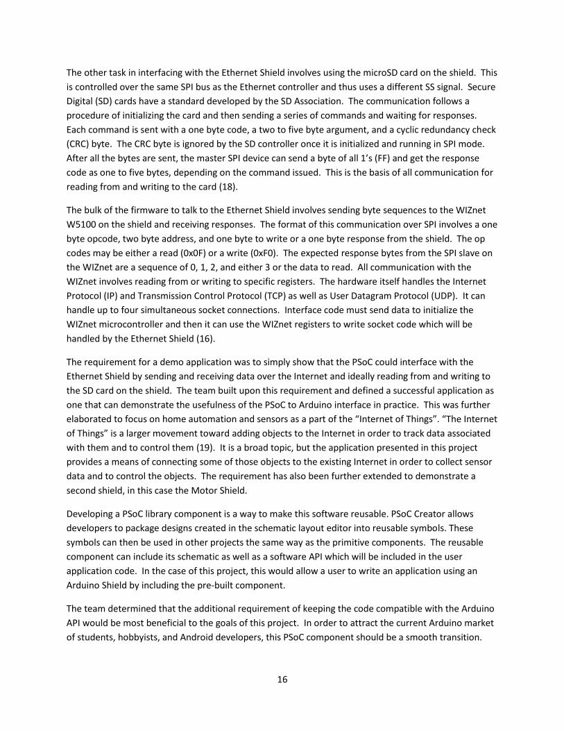
One key configuration had to be changed on the master in slave out (MISO) pin, or digital pin 12 on the
Arduino. By default, the input digital pins in PSoC Creator are set to synchronize with the clock.
However, as the SPI runs on its own clock, it does not make sense to synchronize the input pin with the
system clock. That option must be turned off in the pin properties, as in Figure 10. This was actually a
major source of error in the original design. With this synchronization enabled, the received SPI data
appeared to be only zero.
19
Figure 10 Pin configuration for the MISO pin in order to make SPI work.
The SPI component uses mostly default configurations, with the mode set to “0”, the data bits set to
“8”, the data lines set to “MOSI + MISO”, and the shift direction set to “MSB First”. It does use an
external clock so that the SPI speed can be configured. The clock is currently set at 8 MHz, which is then
divided by two within the SPI component. This is set to make the communication speed similar to that
of the Arduino in order to minimize the chance of transmission error.
The team found while working on the SD card reading and writing that the clock speed of the SPI bus
needed to be changed. The SPI bus must run at no more than 400KHz during the initialization of the SD
card, after which it should be increased to the 4MHz speed as described above. In order to handle this,
a multiplexer (MUX) was added to the clock input on the SPI. This allows the firmware to selectively
change the clock speed between the 800KHz and 8MHz clocks when initializing the SD card. The
updated component is shown in Figure 11.

20
Figure 11 Revised SPI Module in PSoC Creator with multiple clock speeds
Another component that is useful in porting the Arduino library is a counter. The Arduino library has a
function called “millis” which returns the number of milliseconds since the device has been running. It is
used for some of the debug code in Arduino, as well as in a few places to exit if a function times out. In
order to use that code, this project uses a counter which counts to a 1 kHz clock so that each clock pulse
has a 1 millisecond period. Then, the Arduino “millis” function returns the value of that counter. The
component in PSoC Creator is shown in Figure 12. Additional code is required in an initialization
function to start the counter and enable the clock it uses. This initialization must be called by the user.
The function is shown in Listing 3.
Figure 12 PSoC Creator Counter component for implementing the Arduino millis() function
Listing 3 Initialization code to make the counter work.
The complete set of PSoC Creator components has been packaged into a symbol for library reuse. As
stated previously, it was a requirement to package the code into a reusable library module. The symbol
is shown in Figure 13 and includes only a connection to the system clock. The remaining pin connections
are internal to the symbol. It is required that a user configure the physical pin connections for the
void init()
{
`$INSTANCE_NAME`_Counter_1_Init();
`$INSTANCE_NAME`_Counter_1_ClearFIFO();
`$INSTANCE_NAME`_Clock_1_Enable();
`$INSTANCE_NAME`_Counter_1_Start();
}

21
internal SPI pins so that they correspond to the proper general purpose input output pins on the PSoC.
The pin connection was defined by this team during the hardware design phase in order to make the
connections as straightforward as possible.
Figure 13 PSoC Creator reusable component symbol
Problems Encountered During the development of this project, many problems were encountered and had to be overcome for
the design team to move forward. The earliest problems involved compiler and linker errors. After
solving these issues, the problems involved the failure of the code to work properly on the hardware
due to improper connections and SPI configuration. The final issue involved reading the actual data on
the SD card.
The initial problems with compiler errors were originally due to the fact that the Arduino code uses the
GCC toolset with specific standard libraries from AVR. It makes certain assumptions about the
availability of functions which were not available with the version of GCC used by PSoC Creator. Fixing
these issues involved removing references to unavailable functions and replacing code that was still
necessary. One difficult area was the use of a custom string class in Arduino which would require much
custom coding to work with PSoC. The team decided that this string class could be removed in favor of
plain c-style strings.
Another obstacle was in getting the C++ code to work with the PSoC Creator environment. The
environment is designed to compile and link C code. However, it ships with the full GCC toolset and
therefore can compile and link C++ code as well. The Arduino code is primarily written in C++ and was
more useful with its complete C++ interface intact. By default, the PSoC Creator environment would not
even try to build files ending with “.cpp”. This was fixed by modifying the project file for PSoC Creator to
make the software treat those source files as “C files”. This allowed the build system to work. In order
to get C and C++ code compiling together, the team had to resort to a few other tricks. All C++ code
which included Cypress generated C code had to wrap the include directives in ‘extern “C” {}’ blocks in
order to handle the C++ name mangling when linking (21). Certain other issues arise when using C++
code in an embedded environment with very little memory. C++ uses many advanced features such as
polymorphism and virtual methods, templates, and run time type information which can add code bloat
if used improperly (22). Fortunately, the standard Arduino board has a flash memory size of 32 KB,

22
which is the same as the simplest PSoC 5 board. This means that the Arduino library has already been
optimized to work with a similar memory constraint. Also, the Arduino team has already developed
fixes to address limitations which would normally lead to linker errors for features such as pure virtual
functions and the C++ style of memory allocation using “new” and “delete”. The file “new.cpp” handles
these issues and works well for this project. Additionally, this project needed to set the compiler flag “-
fno-rtti” so that the C++ feature of run time type information was not used.
Upon fixing compilation and linking errors, the code needed to be programmed onto the PSoC and
tested. A simple test application was developed which would use the PSoC debugger to set the
initialization code on the WIZnet to set the local IP address and then to read it back and verify that it
was set. However, the team spent several weeks on this testing as the results were simply getting no
data back. The testing methodologies used by the team are outlined in the following chapter. In
summary, the team eventually discovered the misconfiguration of the SPI input (MISO) pin which
allowed the program to work and the project to continue.
The final problem involved getting the SD card reading and writing to work. Unfortunately, the team
was unable to overcome this problem, but has found a partial solution which could be expanded upon
given more time. The current project uses the Arduino SD library which has functions to communicate
over SPI with the micro SD card. It also has classes and functions to handle File Allocation Table (FAT)
file systems. This allows application code to call file open methods and properly use the FAT partitions.
The design team ran into an issue with getting the FAT volume to initialize. Without this initialization, it
is not very convenient to read from or write to the card as the application would have no concept of a
file, and simply be reading and writing raw bytes.
Chapter 4: Test Data with Proof of Functional Design
Final Prototype Description The final design for the hardware is a PCB with the PSoC 5 First Touch kit and the Arduino Ethernet
Shield in a side by side configuration, as shown in the proposed design section,
Figure 3. This design was chosen so that both hardware component s can be easily accessed and
interchanged with other equipment. For example the Arduino Ethernet shield can be changed with an
Arduino motor shield. The software used to program the PSoC is a modified version of Arduino’s open
source C++ code and was compiled using PSoC Creator’s GCC complier, with some modifications in the
PSoC Creator project file to handle C++ files. The virtual components created by the PSoC creator are
implemented using C code and the Ethernet shield, and Arduino libraries in general, are programmed
using C++ code. With the hardware components configured for implementation and stored as a reusable
component in PSoC Creator, the design team can utilize the sensors that come embedded on the PSoC
5. These sensors include a proximity sensor, CapSense slider, thermistor, and accelerometer. In
conjunction with the Ethernet shield, the PSoC can have all information gathered from the sensors and
sent to the internet to be viewed from remote locations. Such an application would be great for
monitoring your home while on vacation or at work. As mentioned in the previous chapter, the team

23
was unable to finalize the SD card reading and writing functionality. The team was unable to debug this
issue due to limitations in the PSoC Creator debugger and a lack of time. However, the remaining
project serves as a useful product, lacking only SD card reading and writing support.
Project Applications In order to demonstrate the functionality of the final prototype, demo applications were developed by
the Design Team. One such application consists of an LED that can be turned on and off, as well as
dimmed from a web browser. This application illustrates the potential to control lights or appliances in
your home through a web browser. The TinyWebServer handlers for blinking an LED and LED status
were modified by the design team. The application utilizes various PSoC Creator components such as the
pulse width modulator (PWM), a digital multiplexer, and a control register in order to dim an LED on the
PSoC First Touch kit.
The second application developed connects the PSoC Arduino Friendly shield to the Pachube web
service. The Pachube service logs sensor data which can then be shared via Twitter or email (13).
Utilizing the temperature sensing capabilities that the PSoC possesses with the thermistor, an alert can
be sent via email if the temperature of your oven or a room in your home is beyond or below a certain
threshold temperature. This demo could be expanded upon to use other sensors on the PSoC First
Touch kit.
The final demo developed intends to illustrate that the design is able to interface with Arduino shields
other than the Ethernet shield. The chosen shield was the Arduino Motor shield. Using the CapSense
slider on board the PSoC First Touch kit, the speed of a small DC motor can be adjusted. The developed
applications are able to showcase the benefits of interfacing PSoC and Arduino shields. The capabilities
of PSoC, specifically the sensing capabilities, and the wide variety of Arduino shields, can offer a great
deal of use when packaged together.
Test Methods Throughout the course of this project, certain diagnostic methods proved invaluable to the process of
rectifying errors. Beyond the use of the PSoC software debugger, certain physical diagnostics also
provided insight in this process, namely the use of a National Instruments DAQPad. This DAQPad allows
for the capturing of high-speed digital waveforms, however, use of this product depends on the creation
of software interfaces to store this data on a computer for visualization (23).
As stated previously, the purpose of the project is the emulation of an Arduino with a PSoC for the use
of an Arduino Ethernet Shield. Therefore it is imperative that the programmed PSoC act in nearly the
same way as the Arduino for these applications, particularly in the production of digital waveforms. The
DAQPad provides a way to measure this, and additional software interfaces can allow for quick and
efficient visualization of the waveforms propagated by the PSoC and Arduino. The DAQPad, contains 24
digital I/O pins to read and process digital data. With easily accessible Labview support, this device
exhibits a wide range of possible functions and can easily adapt to a variety of applications. For the
purposes of debugging the PSoC, the Labview program needs to be able to capture digital values quickly
since the SPI clock of the Arduino can run at a maximum of 4 MHz. To achieve this functionality, the
24
DAQPad is set to capture the state of the MOSI or MISO pin when triggered by a positive edge of the SPI
clock in Labview. However, setting the parameters for clock triggering is not the only specification
needed to properly use the DAQPad.
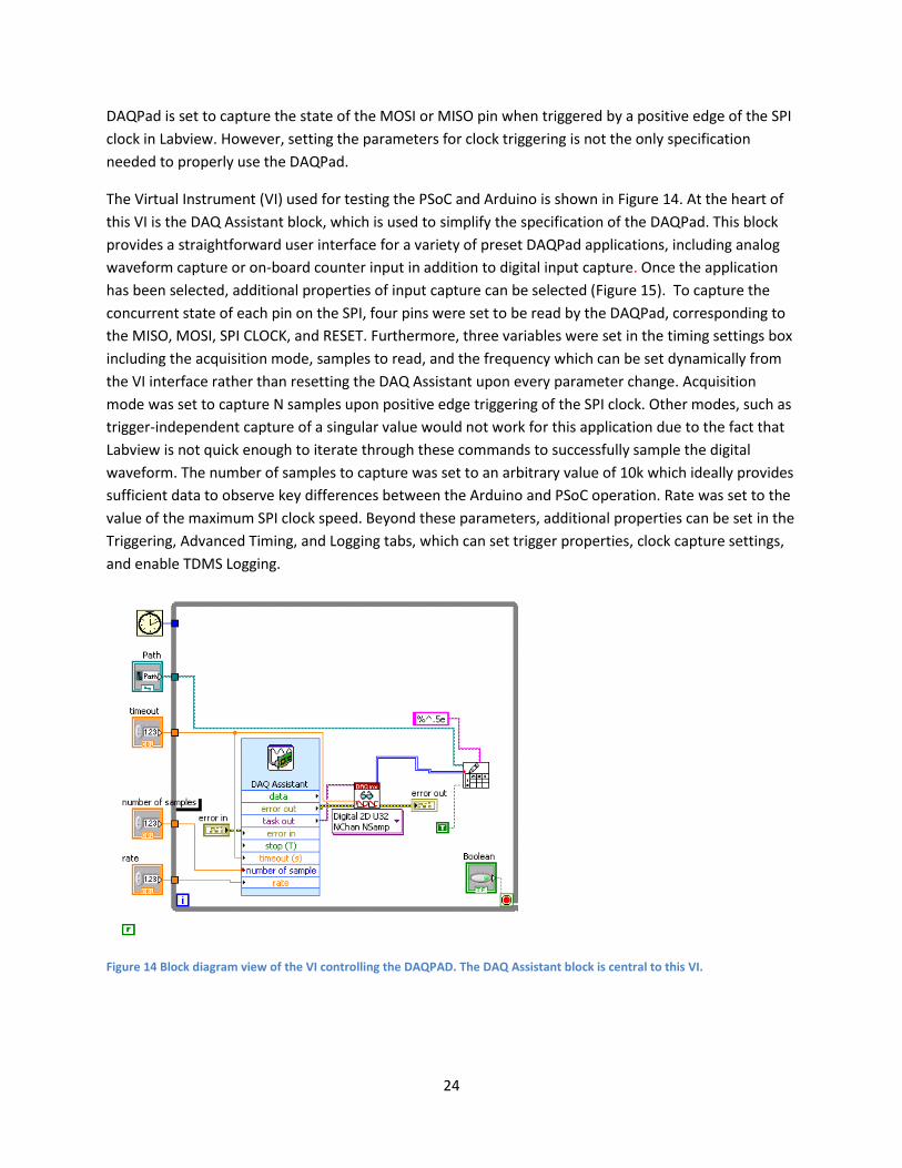
The Virtual Instrument (VI) used for testing the PSoC and Arduino is shown in Figure 14. At the heart of
this VI is the DAQ Assistant block, which is used to simplify the specification of the DAQPad. This block
provides a straightforward user interface for a variety of preset DAQPad applications, including analog
waveform capture or on-board counter input in addition to digital input capture. Once the application
has been selected, additional properties of input capture can be selected (Figure 15). To capture the
concurrent state of each pin on the SPI, four pins were set to be read by the DAQPad, corresponding to
the MISO, MOSI, SPI CLOCK, and RESET. Furthermore, three variables were set in the timing settings box
including the acquisition mode, samples to read, and the frequency which can be set dynamically from
the VI interface rather than resetting the DAQ Assistant upon every parameter change. Acquisition
mode was set to capture N samples upon positive edge triggering of the SPI clock. Other modes, such as
trigger-independent capture of a singular value would not work for this application due to the fact that
Labview is not quick enough to iterate through these commands to successfully sample the digital
waveform. The number of samples to capture was set to an arbitrary value of 10k which ideally provides
sufficient data to observe key differences between the Arduino and PSoC operation. Rate was set to the
value of the maximum SPI clock speed. Beyond these parameters, additional properties can be set in the
Triggering, Advanced Timing, and Logging tabs, which can set trigger properties, clock capture settings,
and enable TDMS Logging.
Figure 14 Block diagram view of the VI controlling the DAQPAD. The DAQ Assistant block is central to this VI.

25
Figure 15 Various properties of the DAQPad operation can be specified by double clicking the DAQ Assistant block
Although the DAQ Assistant block can simplify the process of setting various properties of the DAQPad,
in order to properly record data in a way that can be easily visualized, additional blocks and logic must
be added to the VI. The path for the data file, along with the number of samples, rate, and wait time
until timeout are all specified externally via the user interface of the VI. Concerning the output of the
DAQ assistant, the data type of the captured waveform is subsequently cast to numeric values capable
of being transcribed to a text document upon the total capture of all 10K samples. Once the captured
data is transcribed to a text file, additional software can be used to visualize the waveform such as
Microsoft Excel or Matlab. Data visualization is particularly simple in Matlab, as plotting only takes a
couple of lines. To import data to a matrix from a text file and then subsequently plot this data, two lines
of code can be used:
load filepath;
plot(filename(column_value,:))
where filepath denotes the address for the data file, filename denotes the name of the data file, and
column value is the numeric column of the pin. Additionally, for side-by-side comparison of waveforms
propagated by the Arduino and PSoC the Matlab subplot command can be used. In the context of this
project, side-by-side comparison of the respective waveforms proved invaluable to the process of
diagnosing errors in porting the Arduino code to PSoC. Through recording the serial data propagated by
26
the MOSI in particular, the ported code was found to emulate the Arduino almost identically. Issues in
interfacing with the Ethernet shield with the PSoC were found to come from other factors than the
MOSI waveform.
Another test tool used was an Arduino Duemilanove. The team used this actual Arduino board in order
to have a baseline to compare to the PSoC. This was helpful in ensuring that the Ethernet Shield was
working and in testing some of the demos before writing the code on the PSoC. As mentioned
previously, the Arduino SPI communication was compared to the PSoC using the DAQPad.
The other primary test method used throughout this project was the PSoC Creator debugger. This
proved to be the most useful test method, as it gave the team insight into what the PSoC was doing and
what the values of variables were. The debugger was used to test the actual response bytes of the SPI
during Ethernet and SD card testing. It showed that the SPI was misconfigured, as the bytes received
were not correct. It was also very important in testing the actual demo applications. The PSoC 5 First
Touch kit does not include any additional serial debugging which may allow one to send output to a
computer monitor. Therefore, the debugger in the IDE was invaluable.
Chapter 5: Final Cost, Schedule, Summary and Conclusions
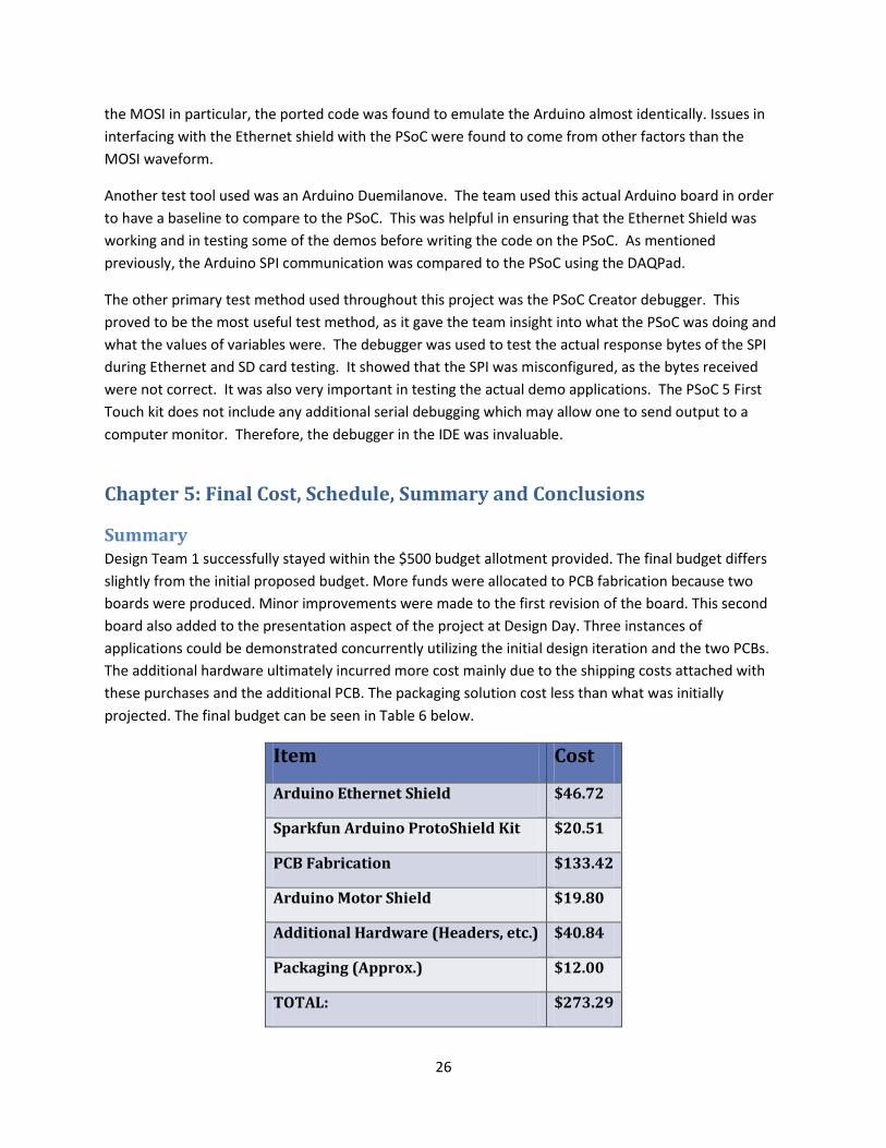
Summary Design Team 1 successfully stayed within the $500 budget allotment provided. The final budget differs
slightly from the initial proposed budget. More funds were allocated to PCB fabrication because two
boards were produced. Minor improvements were made to the first revision of the board. This second
board also added to the presentation aspect of the project at Design Day. Three instances of
applications could be demonstrated concurrently utilizing the initial design iteration and the two PCBs.
The additional hardware ultimately incurred more cost mainly due to the shipping costs attached with
these purchases and the additional PCB. The packaging solution cost less than what was initially
projected. The final budget can be seen in Table 6 below.
Item Cost
Arduino Ethernet Shield $46.72
Sparkfun Arduino ProtoShield Kit $20.51
PCB Fabrication $133.42
Arduino Motor Shield $19.80
Additional Hardware (Headers, etc.) $40.84
Packaging (Approx.) $12.00
TOTAL: $273.29

27
* All costs include shipping (if applicable) Table 6 Final Budget
The project timeline was greatly impacted by the issues with the SPI communication. The projected
completion dates of multiple tasks were affected by this. Ultimately, the design team was able to
localize and correct the issues. This breakthrough put the team back on the schedule presented in the
team’s Gantt chart.
The initial project specifications set by Cypress Semiconductor include writing code to interface the PSoC
platform with the official Arduino Ethernet Shield such that the integrated device can send data over the
internet through webserver application code. This project aims to provide an alternative platform for
Arduino users demonstrating the benefits of PSoC particularly to the demographic of hobbyists and
students. The nature of this project is to provide a very general, accessible product to promote
awareness of the PSoC platform to a new audience; as such many additional aspects of this project can
be developed to more accurately demonstrate the adaptability of this project. To demonstrate
rudimentary functionality of this product, an LED can be controlled via the internet over a web-
interface, a demo which has taken inspiration from pre-existing Arduino demos (10). Therefore, such a
demo could potentially attract Arduino users who have made similar projects to the possibility of using
the PSoC platform. Additionally, a more extensive demo integrating social media and “The Internet of
Things” has been prepared. This demo takes data gathered from the PSoC to potentially trigger email
alerts detailing the nature of the trigger. This demo could be expanded upon using the Pachube
environment to send other alerts or to create useful data visualizations. Such a demo elucidates the
potential of the PSoC platform for more advanced applications involving data transmission over the
internet, such as displaying alerts based on sensor data monitoring house-hold appliances via social
media. These alerts could inform a user of an appliances abnormal temperature for instance, allowing
the user to check the status of a device remotely. Another application that goes above and beyond the
scope of this project is the interfacing of an Arduino Motor Shield with the PSoC. Interfacing with an
additional shield shows the scope of this project and the adaptability of PSoC, that this platform could
potentially be used for any kind of Arduino shield. Although applications like these demonstrate the
potential of PSoC for projects interfacing with Arduino hardware, there is still much work that can be
done to evolve the functionality of this project.
Conclusion One key aspect of this project which could still be improved upon is the ability to communicate with the
SD card on the Ethernet Shield. Although this project has taken code previously used for Arduino to
interface with the Ethernet Shield and ported it to PSoC, the Ethernet connection components function,
and the SD card does not entirely. Further inspection needs to be done to resolve the source of these
errors. Currently, the code is unable to initialize the FAT volume on the SD card and work must be done
to rectify this. Furthermore, future projects could be done to make additional demos to inspire new
users of PSoC, similar to how Arduino provides its users with a variety of demos to work from. Lastly, at
Cypress Semiconductor’s discretion, a completely new Ethernet shield could be fabricated which is
designed and optimized to work with the PSoC specifically rather than reusing the Arduino Ethernet
Shield. Future considerations aside, the final design allows for the PSoC First Touch kit and Arduino

28
shields to be interfaced using the software and hardware solutions provided by Design Team 1. Through
the use of the custom PCB, reusable library component in PSoC Creator, and the ported Arduino
libraries, users can complete projects using the PSoC First Touch kit to program Arduino shields.
Appendix 1: Technical Roles, Responsibilities, and Work Accomplished
Cecilia Acosta – Presentation Prep Cecilia worked on the research and configuration of the pin connections for the
Arduino Ethernet shield and PSoC Shield. Both hardware components needed to be
intensely researched to properly connect the two without future interface issues. She
was also involved in the configuration of the pins using PSoC Creator. Using the
previously done research and the designed pin configuration the information was
added and programmed using PSoC creator. This allowed the PSoC to run properly
when connected to the Ethernet shield.
Cecilia researched several PCB design software to find the most adequate application to create a printed
circuit board for the project. She found that DipTrace was the right software for the task at hand. The
team was able to use a trial version with enough number of traces to cover the project design. The PCB
creation was split into Component design, Pattern Library design, Schematics Layout and the PCB layout.
She was mostly involved with Pattern Library design, Schematics Layout and the PCB layout. The PCB
was designed with the goal of being reusable with different Arduino Shields, as well as leaving it open to
the possibility of using the PCB with the current components as a base design for more extensive
projects. Also, the design was made keeping in mind a possible enclosure, all was made to
measurement to allow for a simple packaging solution.
Cecilia was also involved in the LED demo, specifically the dimming of the lights; she developed a
module to dim the LED using PSoC Creator components. She also designed the web interface for both
light demos, including turning lights on and off, while working with Matt to implement the web server
and javascript code.
Lastly, Cecilia was involved in the design and implementation of the packaging of the project. A pre-
made box was purchased and cut using a bridge port 3 axis milling machine, keeping in mind easy access
and visibility of the hardware components of the project. She also used a Vinyl cutter to create the
labeling of the package to increase the visual appeal of the design.
Brett Donlon – Lab Coordinator Brett Donlon primarily focused on the hardware aspects of Design Team 1’s project.
He researched the various ProtoShields on the market and chose the best one for
connecting the Arduino Ethernet shield to the PSoC First Touch kit. He researched
both the Arduino Ethernet shield and First Touch kit and helped in determining the pin
to pin configurations for interfacing the two boards. He was responsible for assembly
of the ProtoShield, wiring, and soldering of the initial configuration of the project.

29
Once the initial configuration was tested and working, Brett worked on developing the final hardware
design solution as well as the design of the custom PCB. In order to realize the final design, he created
the PSoC First Touch kit and Arduino Shield components and patterns using DipTrace’s Component
Editor and Pattern Editor. Neither of the components were available in the pre-existing component
libraries offered by DipTrace. He created the schematic and layout of the PCB in DipTrace as well. A
second revision of the board was also worked on by Brett with the addition of wider power and ground
traces and a copper pour for elimination of noise. Brett also assisted Cecilia in the packaging solution.
Though Brett’s primary focus was on hardware, his technical contributions also extended into the
software portion of the project as well. He assisted briefly in the debugging of the issue with the SPI
communication between the Ethernet Shield and PSoC First Touch kit. The importance of demonstrating
compatibility with other Arduino shields was also emphasized by Brett as he chose to incorporate
another Arduino shield into the project. An Arduino Motor Shield was purchased and Brett developed a
demo to control a small DC Motor using the PSoC First Touch kit’s CapSense slider. He also helped
brainstorm other applications for demonstrating PSoC-Arduino Ethernet shield compatibility.
Matt Durak – Document Prep Matt Durak is a computer engineer and therefore his technical role was primarily in
the software aspects of this project. Specifically he did more work with the firmware
source code. Matt focused on the Arduino library in his initial research. He learned
how the library worked and how it was organized. He then figured out what parts of
the implementation required changes in order to port the code to the PSoC hardware.
Matt started the work of selecting parts of the Arduino library and building the PSoC
Creator project. The subversion version control system was set up on a shared host
by Matt. The Ethernet library was the primary focus of Matt and Nathan during the early phases of the
project. Eventually, Matt worked on making the SD card library compile on the PSoC. Matt assisted
with the debugging tasks of the Ethernet library when it initially did not work. He wrote some
debugging code which could be run to step through each byte in the SPI transmission. He eventually
discovered the configuration error in the SPI which was causing the Ethernet to fail. Matt assisted the
team in researching possible demo applications and found the Pachube web service as a viable option
for a demonstration. Matt worked with Aaron to assist in debugging the code for the SD card when he
was stuck and learned how the SD standard works in order to better understand the problem. Matt
helped Cecilia turn her LED dimming component into a full demo application by building a web server on
top of it, integrating the component, and writing some javascript to make the interface Cecilia had
designed. In order to make the entire PSoC Creator project easier to work with, Matt created a more
organized project by creating new projects for each demonstration application and a shared library
project with the common code. This shared library project held all of the Arduino library code as well as
the reusable PSoC Creator component. The component was initially set up by other team members but
Matt did the work of creating the library component so that it was reusable.
Aaron Thompson - Webmaster
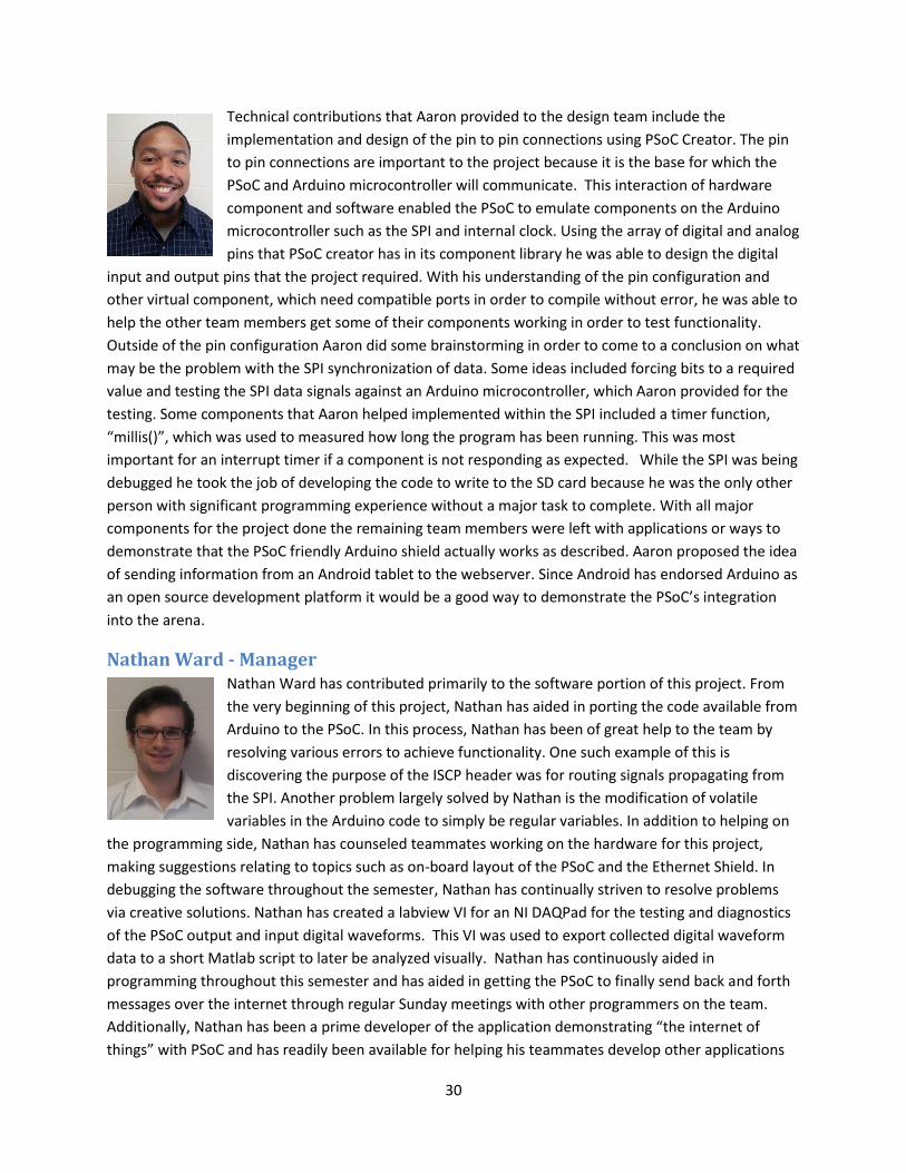
30
Technical contributions that Aaron provided to the design team include the
implementation and design of the pin to pin connections using PSoC Creator. The pin
to pin connections are important to the project because it is the base for which the
PSoC and Arduino microcontroller will communicate. This interaction of hardware
component and software enabled the PSoC to emulate components on the Arduino
microcontroller such as the SPI and internal clock. Using the array of digital and analog
pins that PSoC creator has in its component library he was able to design the digital
input and output pins that the project required. With his understanding of the pin configuration and
other virtual component, which need compatible ports in order to compile without error, he was able to
help the other team members get some of their components working in order to test functionality.
Outside of the pin configuration Aaron did some brainstorming in order to come to a conclusion on what
may be the problem with the SPI synchronization of data. Some ideas included forcing bits to a required
value and testing the SPI data signals against an Arduino microcontroller, which Aaron provided for the
testing. Some components that Aaron helped implemented within the SPI included a timer function,
“millis()”, which was used to measured how long the program has been running. This was most
important for an interrupt timer if a component is not responding as expected. While the SPI was being
debugged he took the job of developing the code to write to the SD card because he was the only other
person with significant programming experience without a major task to complete. With all major
components for the project done the remaining team members were left with applications or ways to
demonstrate that the PSoC friendly Arduino shield actually works as described. Aaron proposed the idea
of sending information from an Android tablet to the webserver. Since Android has endorsed Arduino as
an open source development platform it would be a good way to demonstrate the PSoC’s integration
into the arena.
Nathan Ward - Manager Nathan Ward has contributed primarily to the software portion of this project. From
the very beginning of this project, Nathan has aided in porting the code available from
Arduino to the PSoC. In this process, Nathan has been of great help to the team by
resolving various errors to achieve functionality. One such example of this is
discovering the purpose of the ISCP header was for routing signals propagating from
the SPI. Another problem largely solved by Nathan is the modification of volatile
variables in the Arduino code to simply be regular variables. In addition to helping on
the programming side, Nathan has counseled teammates working on the hardware for this project,
making suggestions relating to topics such as on-board layout of the PSoC and the Ethernet Shield. In
debugging the software throughout the semester, Nathan has continually striven to resolve problems
via creative solutions. Nathan has created a labview VI for an NI DAQPad for the testing and diagnostics
of the PSoC output and input digital waveforms. This VI was used to export collected digital waveform
data to a short Matlab script to later be analyzed visually. Nathan has continuously aided in
programming throughout this semester and has aided in getting the PSoC to finally send back and forth
messages over the internet through regular Sunday meetings with other programmers on the team.
Additionally, Nathan has been a prime developer of the application demonstrating “the internet of
things” with PSoC and has readily been available for helping his teammates develop other applications

31
with this platform. Specifically, Nathan has written code which sends data to a third party datalogging
site named Pachube. Additionally, Nathan has been working on creating a PHP webserver script such
that any data sent by the PSoC to Pachube can potentially set a trigger to create an automatic post on
twitter.
Appendix 2: Literature and Website References 1. Motter, Gregg. Entrepreneurship, Business Model and Business Model Canvas. [Powerpoint] 2010.
2. Cypress Semiconductor Corporation. PSoC Technologoy. [Online] Septemer 18, 2011. [Cited:
September 18, 2011.] http://www.cypress.com/?id=1353&rID=37442.
3. —. Getting Started with PSoC® Creator™. San Jose : s.n., May 31, 2011.
4. Mellis, David A. Arduino - Introduction. [Online] December 23, 2009. [Cited: September 18, 2011.]
http://www.arduino.cc/en/Guide/Introduction.
5. Jimb0. ProtoShield Quickstart Guide. [Online] July 24, 2010. [Cited: September 18, 2011.]
http://www.sparkfun.com/tutorials/191.
6. Fitzgerald, Scott. Arduino Ethernet Shield. [Online] July 9, 2011. [Cited: September 18, 2011.]
http://arduino.cc/en/Main/ArduinoEthernetShield.
7. Motter, Gregg. Function Definition. [Powerpoint] 2008.
8. —. Quality Function Deployment and Selection Matrices. [Powerpoint] 2009.
9. ovidiucp. TinyWebServer. Github. [Online] November 27, 2011. [Cited: December 5, 2011.]
https://github.com/ovidiucp/TinyWebServer.
10. Predescu, Ovidiu. Arduino Tiny Web Server - part 3. Ovidiu Predescu's Weblog. [Online] September
3, 2011. [Cited: December 5, 2011.]
http://www.webweavertech.com/ovidiu/weblog/archives/000484.html.
11. nettigo. P4A – PHP for Arduino part 2. Starter Kit. [Online] May 23, 2011. [Cited: December 5, 2011.]
http://starter-kit.nettigo.eu/tag/fat/.
12. Group, The PHP. PHP. PHP.net. [Online] December 5, 2011. [Cited: December 5, 2011.]
http://www.php.net/.
13. LogMeIn. About Us. Pachube. [Online] December 5, 2011. [Cited: December 5, 2011.]
https://pachube.com/about_us.
14. Twitter. Using OAuth 1.0a. Twitter Developers. [Online] November 17, 2011. [Cited: December 5,
2011.] https://dev.twitter.com/docs/auth/oauth.
15. Cypress Semiconductor. PSoC® 5 FirstTouch™ Starter Kit Guide. [PDF Document] 2011.

32
16. WIZnet Co. W5100 Datasheet. WIZnet. [Online] June 28, 2008. [Cited: December 2, 2011.]
http://www.wiznet.co.kr/UpLoad_Files/ReferenceFiles/W5100_Datasheet_v1.2.2.pdf.
17. Byte Paradigm. Introduction to SPI and I2C Protocols. Byte Paradigm. [Online] July 30, 2010. [Cited:
December 6, 2011.] http://www.byteparadigm.com/kb/article/AA-00255/22/Introduction-to-SPI-and-IC-
protocols.html.
18. Foust, F. Application Note: Secure Digital Card Interface for the MSP430. s.l. : Michigan State
University, 2004.
19. GRIFS. Internet of Things Strategic Research Roadmap. GRIFS. [Online] September 15, 2009. [Cited:
December 7, 2011.] http://www.grifs-project.eu/data/File/CERP-IoT%20SRA_IoT_v11.pdf.
20. Arduino. Arduino. Github. [Online] November 9, 2011. [Cited: November 9, 2011.]
https://github.com/arduino/Arduino.
21. Cline, Marshall. Why is the linker giving errors for C/C++ functions being called from C++/C
functions? C++ FAQ Lite. [Online] July 28, 2011. [Cited: November 9, 2011.]
http://www.parashift.com/c++-faq-lite/mixing-c-and-cpp.html#faq-32.7.
22. Neundorf, Alexander. C vs. C++ for embedded development. KDE Blog. [Online] June 7, 2005. [Cited:
November 9, 2011.] http://blogs.kde.org/node/1138.
23. National Instruments Corporation. NI 625x Specifications. National Instruments Corporate Web Site.
[Online] June 2007. http://www.ni.com/pdf/manuals/371291h.pdf.
24. Arduino Team. Arduino - Homepage. Arduino. [Online] September 24, 2011. [Cited: November 9,
2011.] http://www.arduino.cc/.
25. Mellis, David A. Arduino. Ethernet. [Online] February 10, 2009. [Cited: November 9, 2011.]
http://arduino.cc/en/Reference/Ethernet.
26. Cypress Semiconductor. PSoC 5 Introduction. Cypress. [Online] November 9, 2011. [Cited: November
9, 2011.] http://www.cypress.com/?id=2233&rID=37591.
27. —. PSoC Creator Overview. Cypress. [Online] November 9, 2011. [Cited: November 9, 2011.]
http://www.cypress.com/?id=2494.
28. Zed, Rob. GCC C++ Link problems on small embedded target. Zedcode. [Online] February 17, 2007.
[Cited: November 9, 2011.] http://zedcode.blogspot.com/2007/02/gcc-c-link-problems-on-small-
embedded.html.
29. Hall, Brian. Beej's Guide to Network Programming. Beej.us. [Online] September 8, 2009. [Cited:
November 9, 2011.] http://beej.us/guide/bgnet/output/html/multipage/htonsman.html.
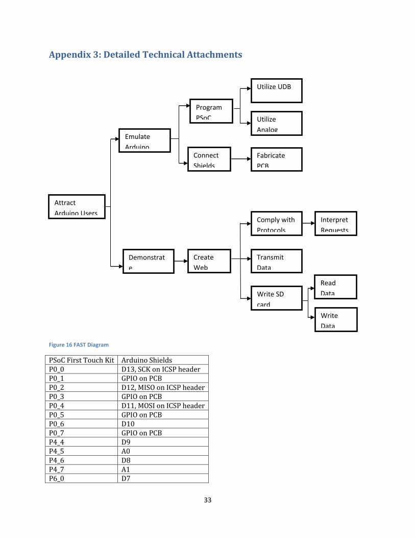
33
Appendix 3: Detailed Technical Attachments
Figure 16 FAST Diagram
PSoC First Touch Kit Arduino Shields P0_0 D13, SCK on ICSP header P0_1 GPIO on PCB P0_2 D12, MISO on ICSP header P0_3 GPIO on PCB P0_4 D11, MOSI on ICSP header P0_5 GPIO on PCB P0_6 D10 P0_7 GPIO on PCB P4_4 D9 P4_5 A0 P4_6 D8 P4_7 A1 P6_0 D7
Utilize
Analog
Interpret
Requests
Transmit
Data
Create
Web
Fabricate
PCB
Comply with
Protocols
Utilize UDB
Read
Data
Demonstrat
e
Emulate
Arduino
Attract
Arduino Users
Connect
Shields
Program
PSoC
Write SD
card
Write
Data

34
P6_1 A2 P6_2 D6 P6_3 A3 P6_4 D5 P6_5 A4 P6_6 D4 P6_7 A5 P12_2 D3 P12_3 D1 P2_6 D2 P2_7 D0 VDDIO 5V VDDIO 5V GND GND GND GND Table 7 Pin Connections between First Touch kit and Arduino Shield
Figure 17 Arduino Friendly PSoC Shield PCB Layout
Source Code Please refer to http://www.egr.msu.edu/classes/ece480/capstone/fall11/group01/


![PROCEEDINGS OF SPIE · Programming the PSoC involves using free and downloadable, but proprietary integrated development system from Cypress (for windows only) - PSoC Creator [X]](https://static.fdocuments.in/doc/165x107/5f75c2971c8f283cfa339110/proceedings-of-spie-programming-the-psoc-involves-using-free-and-downloadable-but.jpg)


