Arduino Based Low-Cost Experimental Unmanned Aerial …
17
Arduino Based Low-Cost Experimental Unmanned Aerial Flight System for Attitude Determination in Autonomous Flights A project present to The Faculty of the Department of Aerospace Engineering San Jose State University in partial fulfillment of the requirements for the degree Master of Science in Aerospace Engineering By Jimmy Rico 2016 approved by Dr. Kamran Turkoglu Faculty Advisor
Transcript of Arduino Based Low-Cost Experimental Unmanned Aerial …
Arduino Based Low-CostExperimental Unmanned Aerial FlightSystem for Attitude Determination in
Autonomous Flights
A project present to The Faculty of the Department of Aerospace Engineering
San Jose State University
in partial fulfillment of the requirements for the degree Master of Science in Aerospace Engineering
By
Jimmy Rico
2016
approved by
Dr. Kamran TurkogluFaculty Advisor
Arduino Based Low-Cost Experimental UnmannedAerial Flight System for Attitude Determination in
Autonomous Flights
Jimmy Rico and Kamran Turkogluy
San Jose State University, San Jose, CA 95192, USA
This paper presents a low-cost experimental test bed of an Unmanned Aerial System (UAS) which isdedicated for autonomous ight testing and control system design. An in-depth look into the integration ofthe hardware is presented along with the design of the software in Arduino IDE and Matlab. The ability tocompare and contrast between hardware and sofware in the loop simulation is developed to demonstratesafe ight char-acteristics for given ight control law design.
Nomenclature
Roll Angle Pitch AngleYaw angle
p Roll Rate q Pitch Rate r Yaw Ratem Massb Wing SpanS Wing AreacMean Aerodynamic CenterIxIyIz
Moment of Inertia about the x-axisMoment of Inertia about the y-axisMoment of Inertia about the z-axisPWM SignalDensity
P PressureRs
TPs
Ps
Speci c Gas ConstantTemperatureStatic PressureTotal Pressure
w Gyro MeasurementCorrection Factor
t
gy
gz
Time di erenceAcceleration in the y-axisAcceleration in the z-axisElevator Command Aileron Command Rudder Command
Graduate Student, Aerospace Engineering, Control Science & Dynamical Systems (CSDy) Laboratory, [email protected]. yAssistant Professor, Aerospace Engineering, [email protected]
1 of 16
American Institute of Aeronautics and Astronautics
I. Introduction
Low-cost avionics set-ups are becoming a commodity in the engineering industry, with vast applicationareas ranging from agriculture to monitoring and many more. Recent work has demonstrated the capabilities of
low-cost ight computers. A great example is Dorbantu's7 avionic system and its ability to demonstrate controllaw design and frequency domain analysis. Quite a few groups have also shown the capabilities of theArduPilot Mega by designing closed loop control laws around the micro-controller through Matlab Simulink
(c)2,9.1 Further, these same articles were able to demonstrate both hardware in the loop and software in theloop simulation. In this paper, as complementary to the existing literature, we present a low-cost basedexperimental research platform of an autonomous Unmanned Aerial System (UAS) which is based solely oneasily accessible o -the-shelf products and open source Arduino software. Here, we aim to demonstrate a lowcost-set up in terms of a blank canvas will be discussed in detail through the design of the avionics system, ightcomputer, to the integration of hardware, and software design to the nal results of the system.
The paper is organized as follows: In Section-II, xed-wing aircraft body frame, avionics system, IMUdevice, GPS system, data logging units, air-speed measurement units, is introduced, while in Section-IIIArduino based software is explained in further details. In Section-IV we provide a brief background on theltering techniques applied to the dynamics, and we explain autonomous control system design in Section-V.In Section-VI we provide the plan of our approach towards system identi cation of the paper and withthe Section-VII, we conclude the paper.
II. Autonomous Unmanned Aerial System (UAS) Test Bed: Ultrastick 25e - Bare Framework
The Ultrastick 25e framework is a xed-wing aircraft body which comes with a suitable compartment, asshown in Fig. 1(b) for any add-on mechanism, device and/or ight computers. This model has the optionbetween aperons or having aileron and aps. For this case, the latter is considered and most analysis isperformed under this con guration. The following, Table 1, de nes the the physical properties of theaircraft at hand.
In the integration phase of the study, the Ultrastick 25e is utilized as the main frame of the UAS, and isused as the test bed along with an 10 DOF IMU, GPS, accelerometer, datalogger, pitot tube and Arduinomicrocontroller. To maintain a low-cost system, all products are based on o -the-shelf and easily availableproducts.
(a) RC Model (b) Avionics Compartment
Figure 1. Ultrastick 25e
A. Arduino Mega
For processing all the information and coding essentials, the Arduino Mega 256014 is used as the main avionicssystem for the model. The reason being that the Arduino Mega 2560 was chosen as the controller for theproject is due to its low-cost, ease of use, online (and freely available) documentation support and functionality.The ArduPilot Mega, another Arduino Mega based micro-controller software system, was
2 of 16
American Institute of Aeronautics and Astronautics

Table 1. Physical Properties of the Aircraft
Property Symbol Value UnitsMass m 1.814 kgWing Span b 1.27 m
Wing Area S 0.31 m2
Mean AC c 0.25 m
Moment of Inertia Ix 0.0653 kg-m2
Moment of Inertia Iy 0.0819 kg-m2
Moment of Inertia Iz 0.1054 kg-m2
examined, but due to the fact that it lacks the ability to integrate various control law designs (such asoptimal, adaptive, robust, nonlinear ... etc.), many of the libraries were re-written, modi ed and coded.This unique perspective provided us the chance to implement any type of control algorithm with the easyuse (and functionality) of Arduino set-up. The software update portion of the project is iterated further inthe following sections.
One of the unique aspects of the Arduino Mega board is that it has the ability to communicate withother hardware components through UART (hardware serial), I2C (two wires), and SPI (4 wire). Amongthese, I2C is easiest to work with because it only requires minimum amount of wires to interface with themicro-controller and it is suitable with the Arduino Libraries. Serial Peripheral Interface (SPI) is commonlyused to send data between micro-controllers and SD card, along with other sensors that require 4 wires tointerface with the Arudino board. It performs this by using a real time clock and data lines. Due to opensource nature, most of the Arduino libraries already exist for many o -the-shelf products and allows todevelop practically anything the user desires, considering the limitations of the micro-controller as shownin the following speci cations.
There are several iterations of the device, to name a few: the Leonardo, the Nano, the Uno, theDuemi-lanove, and the Micro, but the Arduino Mega 2560 provides the necessary memory and thenumber of input/outputs for the ight control system and hardware integration. A summary of the featuresembedded in the Arduino Mega 2560 system are as follows:
ATmega2560 Microcontroller
5V Operating Voltage
7-12v Recommended Input Voltage
54 Digital I/O (15 provide PWM ouput)
16 Analog Inputs
DC Current per I/O Pin 40mA
DC Current for 3.3V Pin 50 mA
4 UARTs (hardware serial ports)
256 KB Flash Memory with 8 KB Memory of RAM
16 Mhz Clock speed
USB connection
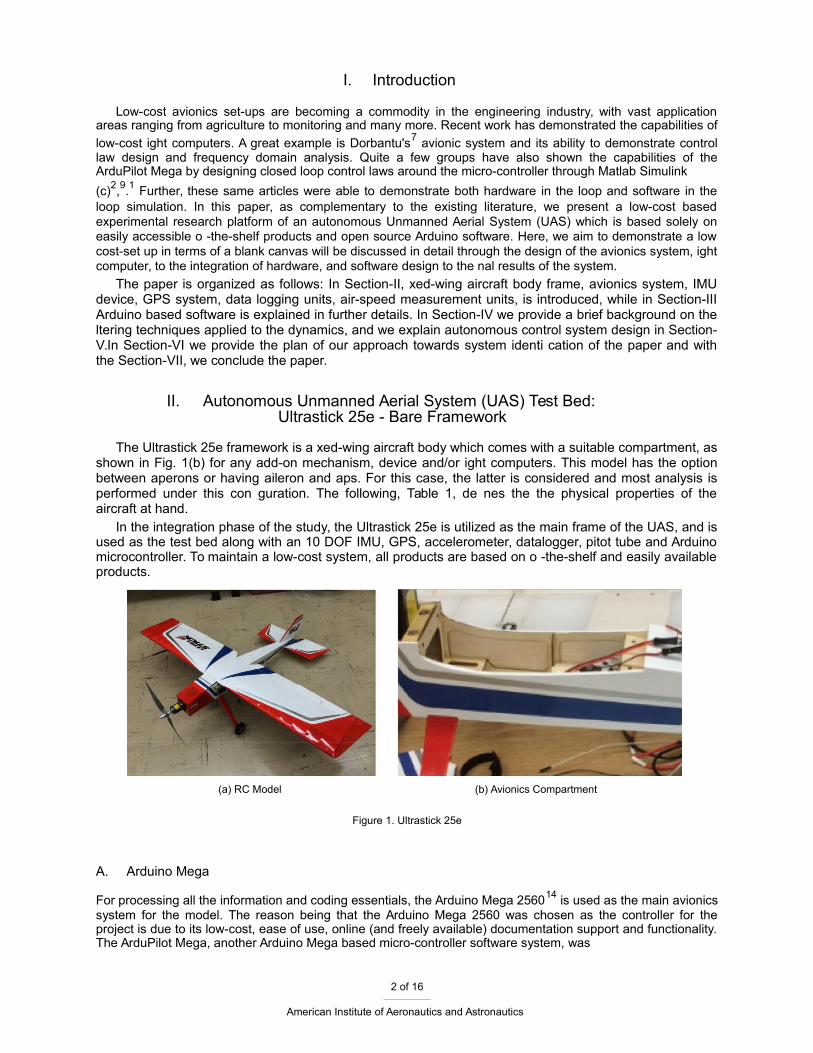
To allow for the integration of all devices and eliminating unecessary wires, a prototyping shield, asshown in Fig. 2, is mounted directly over the Arduino Mega to make installation and harware placementmuch easier for the user. This allows for the integration of the IMU, GPS, SD, including the servo outputpins and receiver input pins to be easily installed. By doing so, this eliminates excessive use of wiring andconnecting the bridge between hardware and micro-controller.
3 of 16
American Institute of Aeronautics and Astronautics
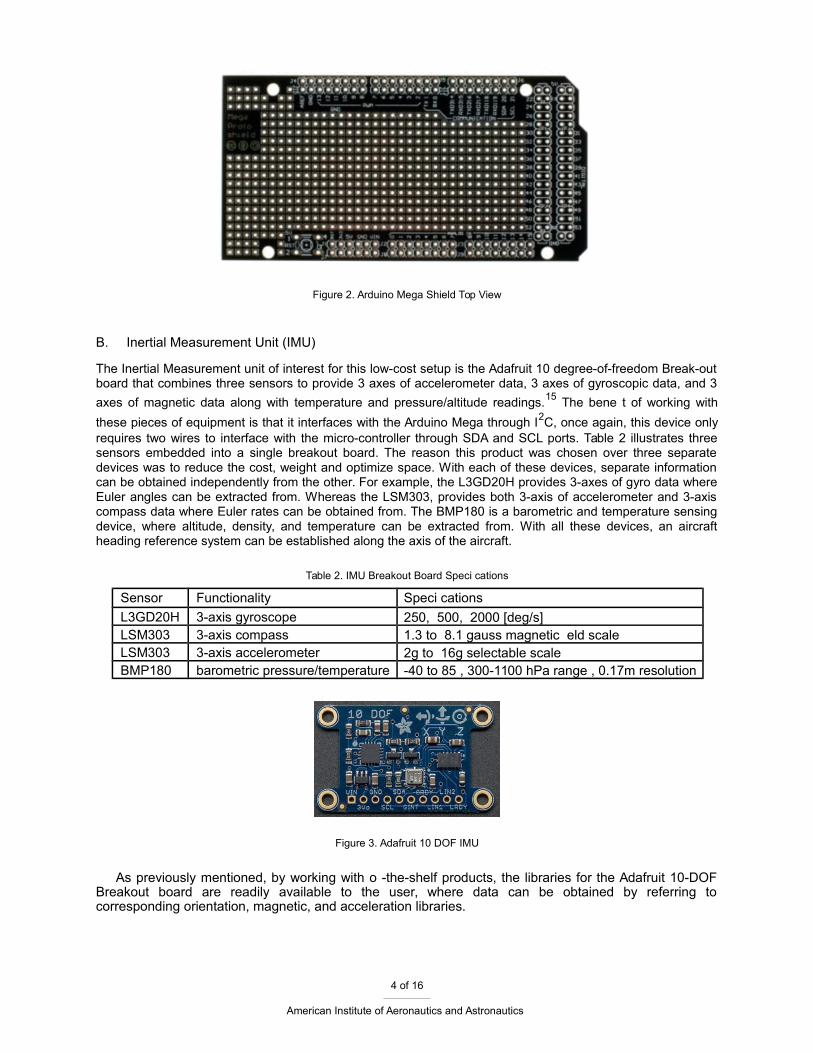
Figure 2. Arduino Mega Shield Top View
B. Inertial Measurement Unit (IMU)
The Inertial Measurement unit of interest for this low-cost setup is the Adafruit 10 degree-of-freedom Break-outboard that combines three sensors to provide 3 axes of accelerometer data, 3 axes of gyroscopic data, and 3
axes of magnetic data along with temperature and pressure/altitude readings.15 The bene t of working with
these pieces of equipment is that it interfaces with the Arduino Mega through I2C, once again, this device onlyrequires two wires to interface with the micro-controller through SDA and SCL ports. Table 2 illustrates threesensors embedded into a single breakout board. The reason this product was chosen over three separatedevices was to reduce the cost, weight and optimize space. With each of these devices, separate informationcan be obtained independently from the other. For example, the L3GD20H provides 3-axes of gyro data whereEuler angles can be extracted from. Whereas the LSM303, provides both 3-axis of accelerometer and 3-axiscompass data where Euler rates can be obtained from. The BMP180 is a barometric and temperature sensingdevice, where altitude, density, and temperature can be extracted from. With all these devices, an aircraftheading reference system can be established along the axis of the aircraft.
Table 2. IMU Breakout Board Speci cations
Sensor Functionality Speci cations
L3GD20H 3-axis gyroscope 250, 500, 2000 [deg/s]LSM303 3-axis compass 1.3 to 8.1 gauss magnetic eld scaleLSM303 3-axis accelerometer 2g to 16g selectable scaleBMP180 barometric pressure/temperature -40 to 85 , 300-1100 hPa range , 0.17m resolution
Figure 3. Adafruit 10 DOF IMU
As previously mentioned, by working with o -the-shelf products, the libraries for the Adafruit 10-DOFBreakout board are readily available to the user, where data can be obtained by referring tocorresponding orientation, magnetic, and acceleration libraries.
4 of 16
American Institute of Aeronautics and Astronautics

C. Global Positioning System (GPS) Unit
The GPS, namely Adafruit Ultimate GPS (as shown in Fig.-4), is another breakout board that has thecapabilities of an update rate of 1-10 Hz, where the update rate can be de ned by the user in the software, with
a velocity accuracy reading within 0.1 m/s and position accuracy reading of <3 m.16 This device is based o theMTK339 chipset, a GPS module that can track 22 satellites on 66 channels with a high sensitivity receiver. Two
unique features that this GPS o ers are the data-logging capabilities and the external antenna functionality.16
With the external antenna, adding a GPS antenna provides an additional 28 dB of gain and allows for theantenna to be mounted along the surface of the wing. Despite its internal data-logging, an external data loggeris used to capture all the necessary information of the aircraft performance.
Figure 4. Adafruit Ultimate GPS
From this device, the longitudinal and lateral position, along with the velocity of the aircraft is obtainedthrough National Marine Electronics Association (NMEA) protocol. Under this method, the user requests astring of information from the GPS and then interprets the data to a more useful value. In this case, thelongitudinal and lateral coordinates as well as the current velocity of the model.
D. Data Logger
Since the data to be stored can become quite large, a class 10 32gb MicroSD card with an estimated 65 MB/swrite speed and a SD breakout board was considered for the project over real-time data logging through anXBee communication device. The reason behind this is that with the XBee, data packets would be lost intransition during testing and the entire system would begin to lag, where the servo command inputs would takeabout a second to respond. To improve the rate at which data would be stored, an embedded data-loggerseemed t and adequate to capture all the necessary data. The current frequency at which the data is stored is72 Hz, where a le is initially created for data to be written and closed when the system shuts o . This methodwas implemented to save time from closing and opening the le after every iteration, and thus increasing thesampling frequency at which the data can be read and stored. This device interfaces with the Arduino Megaover the SPI network, which requires 4 wires for connection. These wires connect directly to the digital pins 50,51, and 52. Additionally, pin 53 is required to select the SD card known as the hardware SS pin. Without thislast pin, the SD library functionality is not guaranteed.
E. Pitot Tube and Airspeed Measurements
To measure the airspeed of the aircraft model, a di erential pressure sensor with a pitot static tube isrequired. The pitot tube of interest is the MPXV7002DP (Airspeed Sensor Kit), which is shown in Fig. 5.This model is designed for micro-processors or micro-controller-based systems and allows for easy
integration through an analog input.19 The pitot tube has the ability to measure positive and negativepressure, but accurate results are obtained when density is also taken into account. With the assistanceof the BMP180, temperature and density values can be used to adjust for changes in pressure at variousaltitudes, thus providing an accurate airspeed reading. For this system, two airspeed sensors areattached on both sides of the wing to estimate an average airspeed over the course of ight.
5 of 16
American Institute of Aeronautics and Astronautics
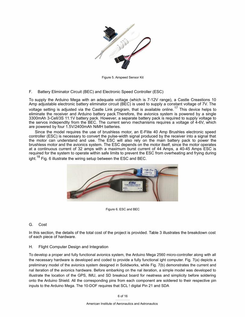
Figure 5. Airspeed Sensor Kit
F. Battery Eliminator Circuit (BEC) and Electronic Speed Controller (ESC)
To supply the Arduino Mega with an adequate voltage (which is 7-12V range), a Castle Creastions 10Amp adjustable electronic battery eliminator circuit (BEC) is used to supply a constant voltage of 7V. Thevoltage setting is adjusted via the Castle Link program, that is available online.17 This device helps toeliminate the receiver and Arduino battery pack.Therefore, the avionics system is powered by a single3300mAh 3-Cell/3S 11.1V battery pack. However, a separate battery pack is required to supply voltage tothe servos independlty from the BEC. The current servo mechanisms requires a voltage of 4-6V, whichare powered by four 1.5V/2400mAh NiMH batteries.
Since the model requires the use of brushless motor, an E-Flite 40 Amp Brushles electronic speedcontroller (ESC) is necessary to convert the pulse-width signal produced by the receiver into a signal thatthe motor can understand and use. The ESC will also rely on the main battery pack to power thebrushless motor and the avionics system. The ESC depends on the motor itself, since the motor operatesat a continuous current of 32 amps with a maximum burst current of 44 Amps, a 40-45 Amps ESC isrequired for the system to operate within safe limits to prevent the ESC from overheating and frying duringight.18 Fig. 6 illustrate the wiring setup between the ESC and BEC.
Figure 6. ESC and BEC
G. Cost
In this section, the details of the total cost of the project is provided. Table 3 illustrates the breakdown costof each piece of hardware.
H. Flight Computer Design and Integration
To develop a proper and fully functional avionics system, the Arduino Mega 2560 micro-controller along with allthe necessary hardware is developed and coded to provide a fully functional ight computer. Fig. 7(a) depicts apreliminary model of the avionics system designed in Solidworks, while Fig. 7(b) demonstrates the current andnal iteration of the avionics hardware. Before embarking on the nal iteration, a simple model was developed toillustrate the location of the GPS, IMU, and SD breakout board for neatness and simplicity before solderingonto the Arduino Shield. All the corresponding pins from each component are soldered to their respective pininputs to the Arduino Mega. The 10-DOF requires that SCL ! digital Pin 21 and SDA
6 of 16
American Institute of Aeronautics and Astronautics

Table 3. Total cost of the UAS set-up integration
Hardware Supplier Product Cost [USD]
RC Model Amazon Ultrastick 25e 169.99
Motor Amazon Power25 69.99
Servos Amazon 6 JR Sport M-48 167.94
Electronic Speed Controller Amazon 40A Brushless ESC 54.99
Reciever Amazon AR7010 7 Channel DSMX 89.99
Propeller Amazon Thin Elec. Prop 12x6E 3.95
Microcontroller Arduino Mega 2560 45.95
IMU Adaftuit 10 DOF IMU 29.95
GPS Adafruit Ultimate GPS 39.95
Data Logger Sparkfun Sparkfun Micro SD 9.99
Pitot Tube 3DRobotics Airspeed Sensor Kit 24.95Total 672.70
! Digital Pin 20. The GPS requires TX ! Pin RX, RX ! Pin TX. SD breakout board requires CS ! Digital Pin53 , DI ! Digital Pin 51 , DO ! Digital Pin 50, SCK ! Digital Pin 52. Fig. 8 illustrates the given receiver inputalong the Analog Pin to Digital Pin outputs for the control surfaces and throttle. Inputs are as follows:Flaps ! A13, Aileron ! A12, Elevator ! A10, Throttle ! A9, and Rudder ! A8. The servo and motor commandsare as follows: D11 ! Elevator, D9 ! Aileron, D8 ! Flaps, D5 ! Rudder, and D3 ! Throttle. Finally, all thecomponents are connected directly to ground and 5V supplied by the Arduino. On the other hand, theservos and the Arduino are powered directly by servo battery pack and the BEC, respectively.
(a) CAD model (b) Flight computer prototype
Figure 7. Flight computer
III. Software
To demonstrate the capabilities of a low-cost unmanned aerial system, the software development con-sists of Matlab, Simulink(c) and Arduino IDE. Within the Arduino IDE, all hardware is controlled by thealgorithm written in Arduino. This includes the software written for the GPS, the IMU, the data-logger, andthe control and interrupt sequence for servo actuation and throttle command. By doing so, control lawsare designed and implemented through hardware in the loop simulation and then analyzed in Matlab andcompared to software in the loop-simulations.
7 of 16
American Institute of Aeronautics and Astronautics

Figure 8. Pin Layout
A. Aircraft Heading Reference System
This section of the code is responsible for reading angular rates, acceleration, and compass heading todevelop the Euler angles and Euler rates, in terms of a body and earth xed axes. The main libraries areprovided by Adafruit for each corresponding sensor Embedded in the 10 DOF breakout board. Throughevery iteration, all of these parameters are updated and recorded at 72 Hz.
B. Controls & Receiver
The control surfaces of the aircraft are controlled through pulse width modulation (PWM) signals sent from theArduino Mega to the control surfaces. In the current architecture, the transmitter sends the command to thereceiver, where each command is transferred into the Arduino Mega through several analog pins, eachcorresponding to the throttle, ailerons, aps, elevator, and rudder. Once the signal has been received, the signalis read by interrupts system embedded in several digital pins on the Arduino Mega board, and when a newcommand has been placed, a ag is raised by the interrupt and tells the system to update the control surface oradjust the rotations of the motor. When the iteration has gone through, the ag is lowered and the processbegins again. This process is conducted to eliminate undesired control surface commands by rst processingincoming commands before relaying out the response. At this phase, control laws can be implemented bysimply switching one of the predetermined knobs/switch on the transmitter. By doing so, the pilot has thecapability of switching between automated sequence and pilot input commands on the y. This is bene cial interms of emergency landing in case the automated sequence fails.
C. Airspeed, Temperature, Pressure and Density
As previously noted, the pitot static system along with the BMP180 are coded to work in unity. The pressuremeasurement requires a simple conversion code that translates a voltage reading to a pressure value. With aknown temperature and pressure value, density is then determined via Eq.(1). Then, Eq.(2) is applied todetermine the airspeed of the aircraft from known static pressure and dynamic pressure values.
8 of 16
American Institute of Aeronautics and Astronautics

= P (1)RsT
Here, Rs denotes the speci c gas constant for air, Pt and Ps are the total pressure and static pressure,respectively.
s2(Pt Ps)
u = (2)
D. GPS
The GPS program allows for the retrieval of latitude, longitude, and velocity of the aircraft through theNMEA command module. The library used for this system is known as TinyGPS. This library was chosenbecause it does not require the use of Software Serial as most other GPS libraries do. Since thetransmitter requires the use of Software Serial, having both devices operate on the same Serial wouldlead to an error and the code would not upload to the micro-controller. Therefore, TinyGPS is the mostsuitable library for the task at hand.
E. Data Logging
The collection of all valuable data begins with the data logger. This piece of software operates byinitializing a le once the system has been turned on, it then converts all data into a string and stores allinformation as an array. The data is recorded in terms of micros(), a command in Arduino IDE that allowsfor data to be analyzed and stored in microseconds. As previously mentioned, all the data is being storedat 72 Hz per iteration.
The data-logging process involves saving the data into a string value. Most of the data is translatedfrom degree to a string with the dtostrf() command in Arduino IDE while operating the SdFat library. Bydoing this, there is no need for the program to continually open and close the SD le to write the data,which actually slows down the system. Thus, to increase the rate at which data is saved, a 510 byte blockis initially created and then the string data could be stored at a much faster rate. When trying to storeoating point values, the system would operate at 20 Hz, but this can only be achieved by opening andclosing the SD le after every iteration. Therefore, to take advantage of the 72 Hz update rate, all datamust be translated into a string and then stored into the SD card as a 510 byte block. The system canhandle a 512 byte block, and a 510 block byte would su ce since most information was less than the specied value. However, if anything exceeds that value, no data could be stored past that block. The remainingportion of data processing is handled through Excel and Matlab, respectively.
F. Control Law Design
At this point, additional control law design can be easily implemented through the current avionics system.This can be achieved via the Arduino IDE or through Matlab Simulink(c). The bene t of using Simuilnk(c)to design control laws is its ease of use and the fact that real-time software in the loop simulation (SIL)allows for the analysis of the current model and make changes accordingly, whereas the HIL wouldrequire to manually transfer the data onto Matlab, analyze the results and then update the information.Further discussion on control law design is provided in Section-V.
IV. Filtering Techniques and Estimation
When relying on sensor measurements for optimal performance, noise can lead to undesired results.To compensate for that error, certain ltering techniques have to be approached. If left un xed, noise mayamplify within the feedback system and lead to undesired results. Therefore, to eradicate the possibility offailure, ltering is a must in these type of schemes where aircraft are highly dependent on synthetic data.The following sections will iterate which type of schemes were chosen to eliminate or minimize this noise.
9 of 16
American Institute of Aeronautics and Astronautics

A. Complementary Filter
To properly adjust the gyro drift measurements and incorrect accelerometer readings during vibrations,both matters are taken into account in the low pass and high pass frequencies. By taking advantage ofthese two parameters, estimated data becomes more precise as compared to the raw data11.8 Analogyprovided in Eq.(3) is applied to aid and correct this issue.
= ( k 1 + wk t) + (1 ) accel;k (3)
Here k 1 is the previous pitch angle value, wk is the angular velocity measured from the gyro, and accel;k isthe pitch angle at that instant given by equation 4 from accelerometer readings.
accl = tan 1
gy
) 0( gz (4)
Here, 0 de nes the correction factor. It was found that = 0.98 provides a clean signal that does notdeviate over time and estimates the angles fairly well, as shown in Fig. 9
B. Kalman Filter
The Kalman lter is an algorithm that uses a series of past measurements and present information overtime to estimate a precise value in respect to the noisy raw value. This technique operates in a recursivematter on noisy data to predict a clean response. After predicting a value, the estimates are yet updatedusing a weighted average, where more weight is given to those with higher certainty. Here Patra (2013)3
, demonstrates the advantages of using a Kalman lter for a missile subjected to two noise inputs, alongwith the derivation of the covariance matrix and weighted matrix and LQR application. The Eq.'s(5-9)demonstrate the Kalman ltering scheme, where more in depth analysis is provided in Patra(2013)3 andLiu (2008),12 as well as many other valuable resources.
xk+1
= F
kx
k +
G
u;ku
k +
G
v;kv
k (5)
yk = Hkxk + Dkuk + ek (6)
Qk = Cov(vk) (7)
Rk = Cov(ek) (8)
In this formulation, x are the state and y are the measurements, e is the error of the system, de ned as
e = x x^ (9)
C. Extended Kalman Filter
Under this method, a similar approach (as seen in the Kalman lter) is applied. However, linear andnon{ linear systems are taken into account, through Eq.(10) and Eq.(11).21 Similarly, the concept is alsoused on GPS and IMU data estimation through an adaptive extended Kalman lter to fuse the informationtogether.20
xk+1 = f(xk; uk; vk) (10)
yk = h(xk; uk; ek) (11)
Then, the solution is determined by taking the Jacobian of f(xk; uk; vk) and h(xk; uk; ek) and assumingGaussian noise, as shown in Eq.(12) and Eq.(13). Further detail on this process is given in Kallapur (2006).21
xk+1 = f(xk; uk) + vk (12)
yk = h(xk; uk) + ek (13)
10 of 16
American Institute of Aeronautics and Astronautics

The following Covariance values for the angle and rate are used for implementation: Qangle = 0:01,Qgyro = 0:0003 with Rangle = 0:01. These values were used with Kalman lter and EKF ltering routines,respectively. However, in experimental validations, EKF provided results which tend to lag dramatically,and requires further investigation. Here, Extended Kalman Filter (EKF) results are not provided due to thelatency issues related to the calculation time within given sampling period, and only Kalman Filter resultstogether with the Complementary Filter results are provided (as shown in Fig.-9), for comparison.
Figure 9. Roll angle measurements through various lters
V. Autonomous Control System Design
The ability to reach a desired response with minimal cost is bene cial to a pilot, or in this case, an RC model aircraft. To properly reach this goal, certain control methodologies have to be accounted for.
A. PID
A PID controller is designed to minimize the control e ort for each of the control surfaces while reaching adesired response. This article9 illustrates the use of all three parameters of the proportional-integral-derivative PID controller, shown in equation 14.10 At times, it may be best to only use one or two of theterms (such as PI, PD), and it is not uncommon to use all three parameters to reach an optimal response.As well known from literature, each term addresses di erent issues in the system.
P ID(s) = Kp(1 +1
+ Tds) (14)Tis
After having developed the proper transfer functions, as shown in Section-VI, a feedback system canbe designed to control the response of the aircraft with respect to a given command. In this case, a pitchand roll controller were developed using P and PD type control algorithms respectively. The results areshown in Fig.-10. The given values are shown in Table 4
Table 4. PID Controller Design Values
Controller P I DPitch -1 0 0Roll 1 0 0.1
VI. System Identi cation
To investigate longitudinal and lateral system dynamics presented and developed in this article arebased on the fundamental ight dynamics theory presented in.13 In addition, a frequency sweep to excitethe natural longitudinal and lateral modes of the aircraft will be performed and then analyzed to producethe proper transfer functions for validation using CIFER23 and Matlab.
11 of 16
American Institute of Aeronautics and Astronautics

Figure 10. Closed loop response for 1o step input.
A. Open Loop Analysis
Considering the fact that the xed wing aircraft is naturally stable, the frequency sweep analysis was per-formed under open loop analysis. Control law design was implemented for self-stabilization, however, thechoice to proceed without a feedback design seemed the best option to capture the true dynamics of theaircraft. Experience tells that investigation of chirp signal response in closed loop dynamics has the
potential to mask (and/or compensate) for mode dynamics, which is not desired.23
To identify a model, a frequency sweep via a chirp signal is taken into e ect. For the case of an aircraft,both longitudinal and lateral modes have to be excited via actuator commands, where the actuator willfollow an automated sinusoidal command at a certain magnitude from 0.01 Hz to 15 Hz for the duration of10 seconds. To develop the lateral system, both rudder command and aileron command have to be takeninto account. When one command is active, the other must remain at trim, and vice-versa. The followingFig. 11 illustrates a chirp command on the rudder, while the ailerons are maintained at trim. From thisdata, the roll rate and yaw rate response are then extracted into CIFER for system identi cation. Thesame procedure is prevalent for the longitudinal dynamics analysis.
B. SISO Identi cation Analysis
For system identi cation, the student version of CIFER23 is used. This software has the capabilities ofproducing state space models as well as transfer functions by analyzing data in the frequency domain.The following, Eq.(15), depicts a transfer function developed , as shown in Fig.-14.
q(s)= e 1
s 51:415s(s + 10:4)(s + 0:1)(15)
(s) (s2 + 0:384s + 0:16)(s2 + 27:24s + 282:6)
where the associated time delay-( ) component is 1 = 0:07.
C. MIMO Identi cation Analysis
In terms of multi-input-multi-output analysis, there were issues in extracting proper data from the studentversion of CIFER as the coherence for several parameters would fall below desired values and not enoughinformation could be extracted. This provides the need for better, cleaner and longer chirp data sets for furtheranalysis. However, Fig. 12 illustrates an adequate coherence plot for yaw rate to a rudder sweep.
12 of 16
American Institute of Aeronautics and Astronautics

Figure 11. Rudder automated chirp analysis
Therefore, proper information could be extracted from this plots and the transfer functions for rudder to yaw rate response, as shown in Eq.(17), and aileron to roll rate, as shown in Eq.(16).
p(s)= e 2
s 115:73s(s2 + 6:262s + 19:45)(16)
(s) (s + 12:34)(s + 0:019)(s2 + 6:906s + 35:32)
r(s)= e 3
s 37:733(s + 7:706)(s2 + 0:54s + 0:81)(17)
(s) (s + 12:34)(s + 0:019)(s2 + 6:906s + 35:32)
where the associated time delay-( ) values are 2 = 0:08 and 3 = 0:06, respectively.
Figure 12. Yaw Rate Coherence in CIFER
13 of 16
American Institute of Aeronautics and Astronautics

D. Validation
To verify the accuracy of the model, an automated doublet command at 7 degree of actuator response isapplied to the aircraft and compared to the results using the identi ed transfer function with the same inputmagnitude. Fig. 13-15 represents a doublet command input on each control surface to their respectiverates. It can be seen that the transfer functions t the actual aircraft response really well and thus validatingthe transfer functions as a good t for the system dynamics.
Figure 13. Yaw Rate Response to Doublet Command of 7 degrees of rudder de ection
Figure 14. Pitch Rate Response to Doublet Command of 7 degrees of elevator de ection
Figure 15. Roll Rate Response to Doublet Command of 7 degrees of aileron de ection
VII. Conclusion
In this paper, successful integration and validation of the hardware and software through the Arduino IDEenvironment and veri ed the results in MATLAB are demonstrated. An in-depth analysis of ltering schemes andight data analysis was performed to produce acceptable results through the use of the Arduino Mega and low-cost components. System identi cation produced an adequate t for the angular rates with their respectivecontrol input, where better and improved results are available through more precise chirp measurements, andis included in the future work. With the presented system identi cation procedure,
14 of 16
American Institute of Aeronautics and Astronautics

control law design becomes achievable and could be easily integrated into the Arduino code to improvethe ight characteristics of the aircraft, which is seen in ight in Fig.16.
Further e orts will be driven to x the important issues between the coherence plots of the remainingstates of the aircraft to produce a full blown state space representation of the system dynamics and allowfor the more advanced (such as Adaptive, Optimal, Robust, ... etc.) control methodologies to be appliedand tested.
Figure 16. Flight testing computer design
VIII. Acknowledgements
The authors would like to thank the George Mateer, a retired Aerospace Engineer and RC hobbyistwho took the liberty and time to y the aircraft during the testing phase of the project and sharing insights.
References
1Coombes, M., McAree, O., Wen-Hua Chen, "Development of an autopilot system for rapid prototyping of high level control algorithms," 2012 UKACC International Conference on Control (CONTROL), IEEE, Piscataway, NJ, USA, 2012, pp. 292-7.
2Esteves, D.J., Moutinho, A., and Azinheira, J.R., "Stabilization and Altitude Control of an Indoor Low-Cost Quadro-tor: Design
and Experimental Results," Autonomous Robot Systems and Competitions (ICARSC), 2015 IEEE International Conference on,2015, pp. 150-155.
3Patra, N., Halder, K., Routh, A., Mukherjee, A., and Das, S. (2013). Kalman lter based optimal control approach for attitude
control of a missile. Paper presented at the Computer Communication and Informatics (ICCCI), 2013 International Conference on,1-4. doi:10.1109/ICCCI.2013.6466158
4Lie, F. A., & Gebre-Egziabher, D. (2013). Synthetic air data system. Journal of Aircraft, 50(4), 1234-1249.
doi:10.2514/1.C0321775Shiau, J., & Wang, I. (2013). Unscented kalman ltering for attitude determination using MEMS sensors. Journal of Applied
Science and Engineering, 16(2), 165-176. doi:10.6180/jase.2013.16.2.086Soken, H. E., & Hajiyev, C. (2009). Adaptive unscented kalman lter with multiple fading factors for pico satellite attitude
estimation. Paper presented at the 2009 4th International Conference on Recent Advances in Space Technologies (RAST 2009),541-6. doi:10.1109/RAST.2009.5158254
7Dorobantu, A., Murch, A., Mettler, B., & Balas, G. (2013). System identi cation for small, low-cost, xed-wing unmanned aircraft.
Journal of Aircraft, 50(4), 1117-30. doi:10.2514/1.C0320658Euston, M., Coote, P., Mahony, R., "A complementary lter for attitude estimation of a xed-wing UAV," Intelligent Robots and
Systems, 2008. IROS 2008. IEEE/RSJ International Conference on, 2008, pp. 340-345.9Sufendi, Trilaksono, B.R., Nasution, S.H., "Design and implementation of hardware-in-the-loop-simulation for uav using pid
control method," Instrumentation, Communications, Information Technology, and Biomedical Engineering (ICICI-BME), 2013 3rdInternational Conference on, 2013, pp. 124-130.
10Zhang Peng, and Liu Jikai, "On new UAV ight control system based on Kalman & PID," Intelligent Control and Information
Processing (ICICIP), 2011 2nd International Conference on, Vol. 2, 2011, pp. 819-823.
15 of 16
American Institute of Aeronautics and Astronautics

11 Coopmans, C., Jensen, A.M., and YangQuan Chen, "Fractional-order complementary lters for small unmanned aerial system navigation," Unmanned Aircraft Systems (ICUAS), 2013 International Conference on, 2013, pp. 754-760.
12 Liu, C., Zhou, Z., and Fu, X., "Attitude determination for MAVs using a Kalman lter," Tsinghua Science and Technology, Vol. 13, No. 5, 2008, pp. 593-597.
13 Cook, M.,Flight Dynamics Principles:A linear system approach to aircraft stability and control, 3rd ed., Elsevier, Burling-ton,MA, 2013
14 "Arduino 2015, available http://www.arduino.cc/en/Main/ArduinoBoardMega2560"15 "Adafruit 2015, available http://www.adafruit.com/product/1604"16 "Adafruit 2015, available http://www.adafruit.com/products/746"17 "CastleCreations, available http://www.castlecreations.com/"18 "E ite 2015, available http://www.horizonhobby.com/ultra-stick-25e-arf-e 4025"19 "Robotshotp 2015, available http://www.robotshop.com/en/airspeed-sensor-kit.html"20 Xiaogang Wang, Jifeng Guo, and Naigang Cui, "Adaptive extended Kalman ltering applied to low-cost MEMS IMU/GPS integration for UAV,"
Mechatronics and Automation, 2009. ICMA 2009. International Conference on, 2009, pp. 2214-2218.21 Kallapur, A.G., and Anavatti, S.G., "UAV Linear and Nonlinear Estimation Using Extended Kalman Filter," Compu-tational Intelligence for
Modelling, Control and Automation, 2006 and International Conference on Intelligent Agents, Web Technologies and Internet Commerce, InternationalConference on, 2006, pp. 250-250.
22 Guoqiang Mao, Drake, S., and Anderson, B.D.O., "Design of an Extended Kalman Filter for UAV Localization," Infor-mation, Decision and Control, 2007. IDC '07, 2007, pp. 224-229.
23 Tischler, M. B., and Remple, R. K., Aircraft and Rotorcraft System Identi cation: Engineering Methods and Flight Test Examples, 2nd ed., AIAA Education Series, AIAA, Reston, VA, 2012,
16 of 16
American Institute of Aeronautics and Astronautics