ARDU-5351 manual english · 2019-05-10 · ARDU-5351 Page 2 INTRODUCTION The ARDU-5351 is an signal...
11
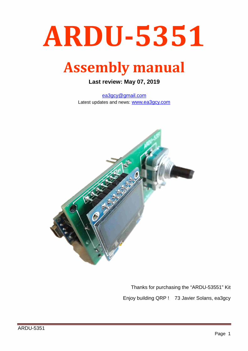
ARDU-5351 Page 1 ARDU-5351 Assembly manual Last review: May 07, 2019 [email protected] Latest updates and news: www.ea3gcy.com Thanks for purchasing the “ARDU-53551” Kit Enjoy building QRP ! 73 Javier Solans, ea3gcy
Transcript of ARDU-5351 manual english · 2019-05-10 · ARDU-5351 Page 2 INTRODUCTION The ARDU-5351 is an signal...
ARDU-5351 Page 1
ARDU-5351 Assembly manual
Last review: May 07, 2019
[email protected] Latest updates and news: www.ea3gcy.com
Thanks for purchasing the “ARDU-53551” Kit
Enjoy building QRP ! 73 Javier Solans, ea3gcy

ARDU-5351 Page 2
INTRODUCTION
The ARDU-5351 is an signal generator based on the SI5351 clock generator chip from Silicon Labs (www.silabs.com) and a Arduino Nano module controller. The use of a "sandwich" single block mechanical configuration and a single encoder with a built-in push-button to control the operation makes this VFO/DDS an extremely versatile "block" easy to integrate in many projects for amateur rigs.
• Three simultaneous outputs, one variable frequency and two fixed frequency. • Simple and flexible configuration through on screen menus. • Clear and bright low current OLED display. • Compact very small overall size. • Simple control via a rotary encoder with push witch. • Low power consumption. • Wide frequency range. • Selectable frequency steps. • IF offset function. • Minimum and maximum frequency adjustable. • S-Meter on/off function. • Receiver incremental Tuning (RIT). • RX/TX indication. • Power supply voltage display. • Calibration of SI5351 crystal frequency and voltaje-meter. • Easy mounting using the rotary encoder shaft. • PCB comes with all SMD parts pre-soldered.
ELECTRIC SPECIFICATIONS
• Controls: Rotary encoder with pushbutton switch. • Display: OLED 0.96” SPI monochrome. • Signal outputs: 2 x fixed frequency and 1 variable frequency. • Fixed output frequency range: 50kHz to 99.9MHz. • Variable output frequency range: 50kHz to 99.9MHz. • IF offset: VFO = F + IF, VFO = F + IF, VFO = IF –F, OFFSET = 0. • Receiver incremental Tuning (RIT) range: no limit. • TX logic input for RIT to GND for TX (5V max. for RX). • Frequency steps: first range 10Hz, 100Hz, 1kHz, second range 10kHz, 100kHz, 1MHz. • Output level: about >3V pp Hi Z. 2V pp 50 ohms. • Reverse polarity protection: series diode. • Connectors: 2,45mm pin strip • Operating supply voltage range: 7 to 15V DC. • Average operating current: 90mA. • PCB size: 65 x 30 mm
ARDU-5351 Page 3
PART ONE:
ASSEMBLY AND INSTALLATION
PLEASE READ THOROUGHLY ALL THE MANUAL AT LEAST ONCE BEFORE ANY WORK IS DONE. All SMD components on the PCB are factory pre soldered. There is very little assembly work.
Look carefully the photos and drawings before starting to solder any parts.
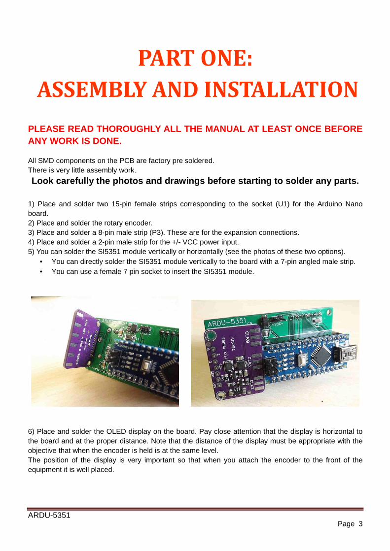
1) Place and solder two 15-pin female strips corresponding to the socket (U1) for the Arduino Nano board. 2) Place and solder the rotary encoder. 3) Place and solder a 8-pin male strip (P3). These are for the expansion connections. 4) Place and solder a 2-pin male strip for the +/- VCC power input. 5) You can solder the SI5351 module vertically or horizontally (see the photos of these two options).
• You can directly solder the SI5351 module vertically to the board with a 7-pin angled male strip. • You can use a female 7 pin socket to insert the SI5351 module.
6) Place and solder the OLED display on the board. Pay close attention that the display is horizontal to the board and at the proper distance. Note that the distance of the display must be appropriate with the objective that when the encoder is held is at the same level. The position of the display is very important so that when you attach the encoder to the front of the equipment it is well placed.
ARDU-5351 Page 4
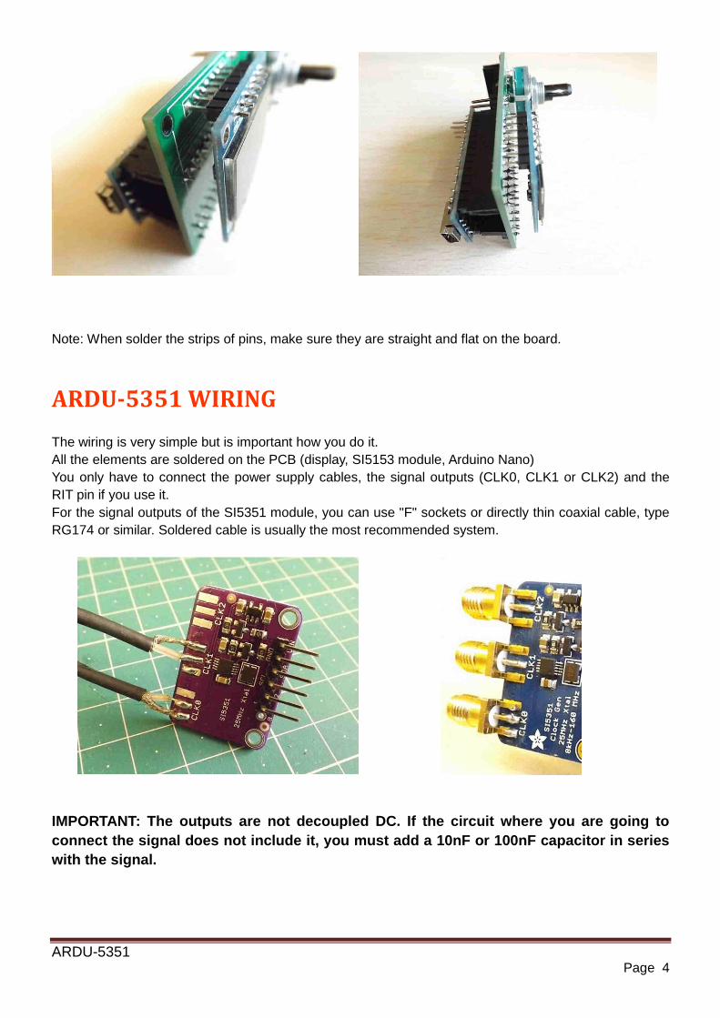
Note: When solder the strips of pins, make sure they are straight and flat on the board.
ARDU-5351 WIRING
The wiring is very simple but is important how you do it. All the elements are soldered on the PCB (display, SI5153 module, Arduino Nano) You only have to connect the power supply cables, the signal outputs (CLK0, CLK1 or CLK2) and the RIT pin if you use it. For the signal outputs of the SI5351 module, you can use "F" sockets or directly thin coaxial cable, type RG174 or similar. Soldered cable is usually the most recommended system.
IMPORTANT: The outputs are not decoupled DC. If the circuit where you are going to connect the signal does not include it, you must add a 10nF or 100nF capacitor in series with the signal.
ARDU-5351 Page 5
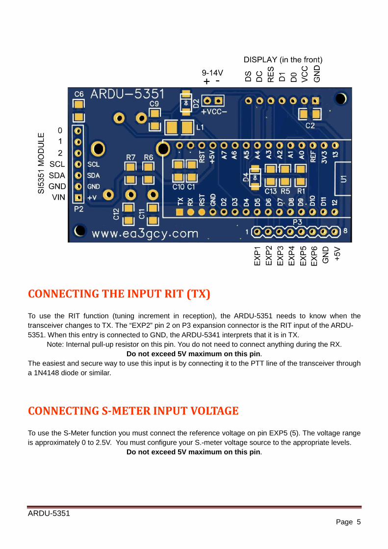
CONNECTING THE INPUT RIT (TX) To use the RIT function (tuning increment in reception), the ARDU-5351 needs to know when the transceiver changes to TX. The “EXP2” pin 2 on P3 expansion connector is the RIT input of the ARDU- 5351. When this entry is connected to GND, the ARDU-5341 interprets that it is in TX.
Note: Internal pull-up resistor on this pin. You do not need to connect anything during the RX. Do not exceed 5V maximum on this pin.
The easiest and secure way to use this input is by connecting it to the PTT line of the transceiver through a 1N4148 diode or similar.
CONNECTING S-METER INPUT VOLTAGE To use the S-Meter function you must connect the reference voltage on pin EXP5 (5). The voltage range is approximately 0 to 2.5V. You must configure your S.-meter voltage source to the appropriate levels.
Do not exceed 5V maximum on this pin.

ARDU-5351 Page 6
SCHEMATIC
ARDU-5351 Page 7
PART TWO
PROGRAMMING AND USING
FACTORY CONFIGURATION/RESET
The Factory and Reset settings are the following parameters: MINIMUM FREQUENCY: 3.000.000MHz MAXIMUM FREQUENCY: 50.000.000MHz IF FREQ: 9.000.000MHz
CLK1: 12.000.000MHz CLK2: 4.000.000MHz CAL FREQ: 0 CAL VOLT: 15V maximum RIT ON/OFF: OFF CHANGE STEPS: 1 kHz - 100 Hz – 10Hz S-METER function: Off
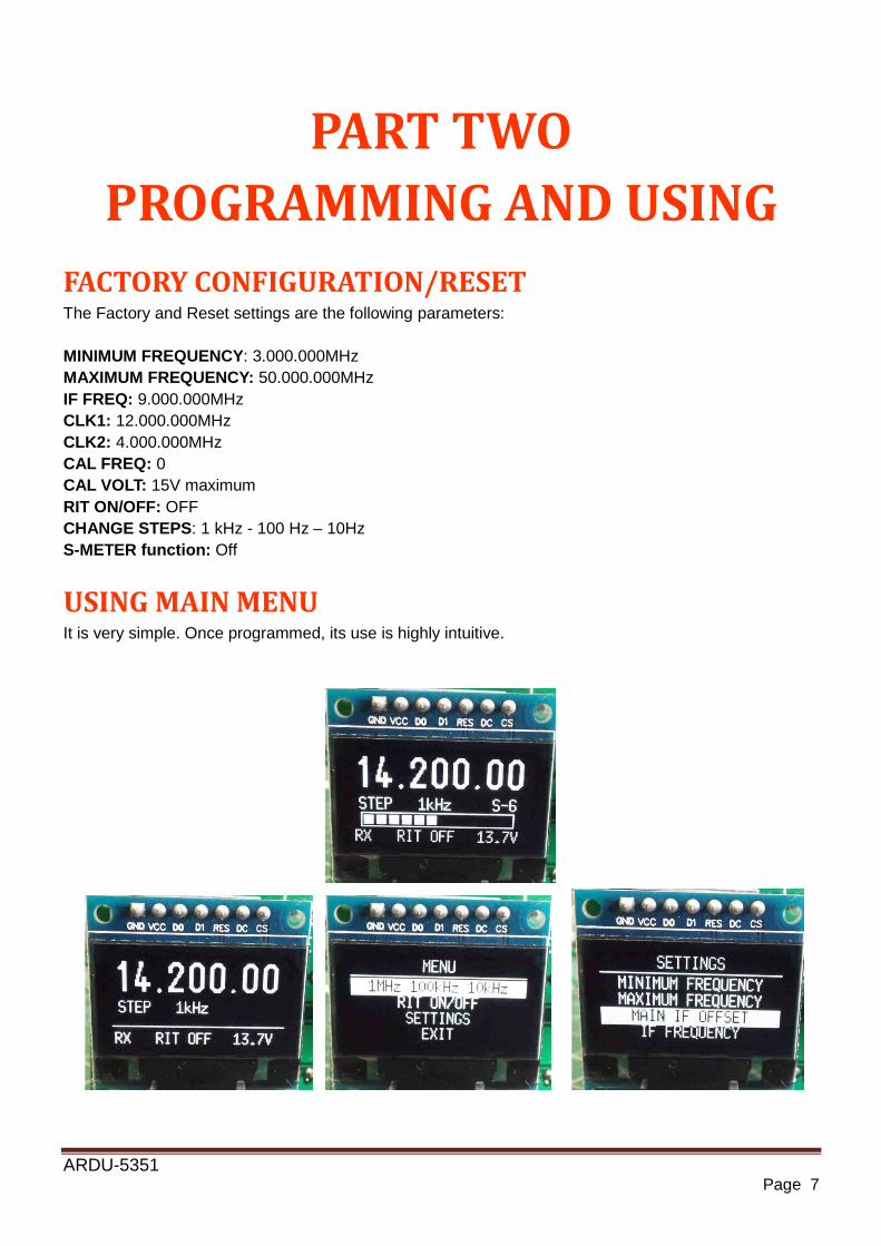
USING MAIN MENU
It is very simple. Once programmed, its use is highly intuitive.
ARDU-5351 Page 8
Dial tuning and step change: By turning right or left the rotary encoder the frequency respectively increases or decreases by the current "step". A quick push on the encoder will change the step. There are two ranges of steps. The default range is 10Hz - 100Hz - 1kHz. To change to the second range of steps, go to menu. To enter the menu, you must pushing and holding the encoder pushbutton for >1 second. Then, you can move through the menu lines by turning the encoder. One of the lines is “EXIT” to exit without change.
MENU
1MHz 100kHz 10kHz RIT ON/OFF SETTINGS
EXIT Steps range change: Press and hold the encoder switch for more than 1 second and select the line "1MHz 100kHz 10kHz" and push switch encoder again. To return to the previous range, repeat the same operation.
RIT on/off: To activate the RIT, press and hold the encoder switch and select the "RIT ON / OFF" line and press the encoder switch again. Then, RIT ON will appear on the main screen. If the frequency increases, "RX+" will appear or if it decreases, "RX-" will appear. If the frequency does not change, "RX=" will appear. When transmitting, the frequency will always return to the initial one. To deactivate the RIT, proceed as in activation.
SETTINGS: Selecting this line, you can enter the settings menu.
EXIT: Return to the main tuning screen.
ARDU-5351 Page 9
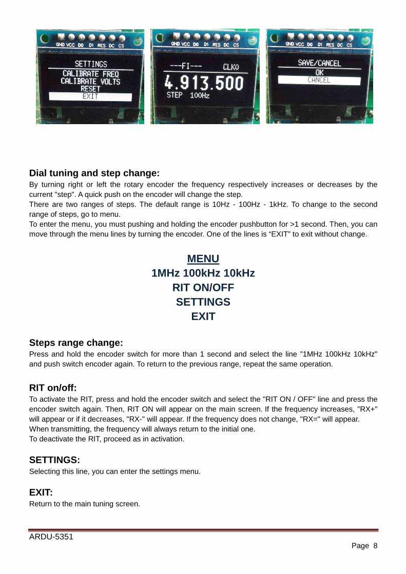
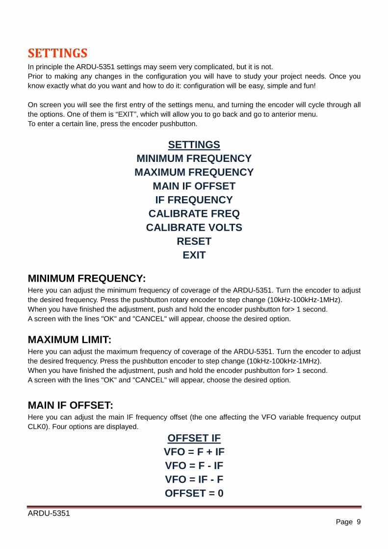
SETTINGS In principle the ARDU-5351 settings may seem very complicated, but it is not. Prior to making any changes in the configuration you will have to study your project needs. Once you know exactly what do you want and how to do it: configuration will be easy, simple and fun! On screen you will see the first entry of the settings menu, and turning the encoder will cycle through all the options. One of them is “EXIT”, which will allow you to go back and go to anterior menu. To enter a certain line, press the encoder pushbutton.
SETTINGS MINIMUM FREQUENCY MAXIMUM FREQUENCY
MAIN IF OFFSET IF FREQUENCY
CALIBRATE FREQ CALIBRATE VOLTS
RESET EXIT
MINIMUM FREQUENCY: Here you can adjust the minimum frequency of coverage of the ARDU-5351. Turn the encoder to adjust the desired frequency. Press the pushbutton rotary encoder to step change (10kHz-100kHz-1MHz). When you have finished the adjustment, push and hold the encoder pushbutton for> 1 second. A screen with the lines "OK" and "CANCEL" will appear, choose the desired option.
MAXIMUM LIMIT: Here you can adjust the maximum frequency of coverage of the ARDU-5351. Turn the encoder to adjust the desired frequency. Press the pushbutton encoder to step change (10kHz-100kHz-1MHz). When you have finished the adjustment, push and hold the encoder pushbutton for> 1 second. A screen with the lines "OK" and "CANCEL" will appear, choose the desired option.
MAIN IF OFFSET: Here you can adjust the main IF frequency offset (the one affecting the VFO variable frequency output CLK0). Four options are displayed.
OFFSET IF VFO = F + IF VFO = F - IF VFO = IF - F OFFSET = 0
ARDU-5351 Page 10
Turn the encoder to select the desired option and press the pushbutton encoder. Example: F = 14MHz and IF = 9MHz. Then, VFO can be 23MHz or 5MHz. VFO = F + IF or VFO = F – IF Note that when the FI is inverted, the sideband is also inverted.
IF FREQUENCY: Here you can adjust the frequency of the main IF (the one affecting the VFO variable frequency output CLK0) or the fixed frequencies of the CLK1 or CLK2 outputs. Turn the encoder to select the desired option and press the pushbutton encoder.
SELECT IF MAIN IF CLK0
SECOND IF CLK1 THIRD IF CLK2
Turn the encoder to adjust the desired frequency. Press the pushbutton rotary encoder to step change (1Hz-10Hz-100Hz-1kHz-10kHz-100kHz-1MHz). When you have finished the adjustment, push and hold the encoder pushbutton for> 1 second. A screen with the lines "OK" and "CANCEL" will appear, choose the desired option.
Note: To disable CLK1 or CLK2 outputs, set the frequency to 50,000 (50kHz) CALIBRATE FREQ: You can calibrate the frequency of the clock crystal oscillator of the SI5351 module. It has a margin of adjustment -2000 to +2000. This value is inverse to the output frequency, that is, when it is increased, the frequency decreases and vice versa. In order to make this adjustment you must use a professional frequency meter or a good quality receiver to read the output frequency of the SI5351 (you can use any of the three outputs CLK0, CL1 or CLK2). If you use the output CLK0, make the adjustment with offset "OFFSET = 0". This adjustment compensates the tolerances of the crystals of each SI5351 module. Notable differences are observed in crystals from different manufacturers.
CALIBRATE VOLTS: You can calibrate the main screen voltmeter. Use a quality multimeter in the volts function. Measure the input voltage of the ARDU-5351. Turn the encoder until the same reading is displayed on ARDU-5351 as on the multimeter. The measurement resolution is 0.1V.
RESET: If necessary, you can perform a RESET to the factory default values. Choose the RESET line and then choose "OK" or "CANCEL".
EXIT: Returns to the previous menu screen.

ARDU-5351 Page 11
S-Meter ON/OFF function
To enable or disable the S-Meter function. Turn on the power while holding down pushbutton rotary encoder. This will invert the state from ON to OFF or vice versa. The ARDU-5351 will always maintain that status until you change it again.
LIMITED WARRANTY
Please read carefully PRIOR to do any work with your kit. All parts provided with this kit are guaranteed against any fabrication defect for one year after the sale. The buyer has the option to examine the kit and the instruction manual for 10 days. If during this period he or she decided not to build the kit, it will be possible to send the kit back, with all shipping charges payed by the customer. The seller shipping charges and all other costs involved (Ebay or Paypal charges) will not be reimbursed. If you plan to ship it back, PLEASE CONSULT how to do it to [email protected] Javier Solans, ea3gcy, guarantees that when the kit is built and adjusted following the information enclosed in this manual, and it is used according to the advices mentioned, it will work according to its specifications. It is your duty to follow the advices and recommendations of this manual, correctly identify the parts, use good working procedures and have access and correctly use the tools and instruments requirede for the assembly and adjustment of the kit. In case you think any part for the kit is missing, please make an inventory of all parts with the parts list included on the manual. Please revise all bags, envelopes or boxes carefully. If something is missing, please send me an email and I will mail you the part right away. Even if you don't want to bother with a common part you may have on your junk-box or a local store, please let me know so I can help other customers with a similar problem. I can also provide a part that you have broken, dammaged or lost by accident. In case you find any errata or mistake on this manual, or you like to make a comment, please get in touch with me at [email protected] Enjoy building QRP! 73 Javier Solans, ea3gcy