ARCTIC OIL SPILL RESPONSE TECHNOLOGY D. … 4.2 Lamor brush bucket skimmer cleaning the ... Figure...
120
i Ff D. Dickins – DF Dickins Associates, LLC May 3, 2017 ARCTIC OIL SPILL RESPONSE TECHNOLOGY JOINT INDUSTRY PROGRAMME SYNTHESIS REPORT
Transcript of ARCTIC OIL SPILL RESPONSE TECHNOLOGY D. … 4.2 Lamor brush bucket skimmer cleaning the ... Figure...

i
Ff
D. Dickins – DF Dickins Associates, LLC
May 3, 2017
D. Dickins – DF Dickins Associates, LLC
May 3, 2017
ARCTIC OIL SPILL RESPONSE TECHNOLOGY
JOINT INDUSTRY PROGRAMME
SYNTHESIS REPORT

ii

iii
ACKNOWLEDGMENTS
The International Association of Oil and Gas Producers would like to thank all of the scientists, specialists and
research organisations whose collaborative efforts made the Arctic Oil Spill Response Technology Joint Industry
Programme (JIP) possible.
On behalf of the JIP, the IOGP would also like to thank the Norwegian Coastal Administration and the Norwegian
Clean Seas Association for Operating Companies for providing the opportunity and marine/air resources to enable
the JIP to participate in the Oil-on-Water 2016 exercise (4.3.7).

iv
TABLE OF CONTENTS
Acknowledgments ............................................................................................................................................. iii
Table of Contents .............................................................................................................................................. iv
List of figures and tables ................................................................................................................................. vi
List of Acronyms ............................................................................................................................................. viii
Executive Summary .......................................................................................................................................... x
1 Introduction and Background................................................................................................................. 1
1.1 Concurrent Oil Spill Research .......................................................................................................................... 3
2 Arctic Oil Spill Research History ........................................................................................................... 7
2.1 Overview of Arctic Oil Spill Research History ................................................................................................ 7
2.2 Arctic Oil Spill Response State of Knowledge and Capabilities at JIP Launch ............................................... 7
2.2.1 Mechanical Containment and Recovery ..................................................................................... 8
2.2.2 In-situ Burning .......................................................................................................................... 10
2.2.3 Dispersant Application ............................................................................................................. 12
2.2.4 Detection and Mapping including Remote Sensing .................................................................. 14
2.2.5 Trajectory Modelling ................................................................................................................ 16
2.2.6 Environmental Effects - NEBA ................................................................................................ 17
3 JIP Scope and Approach ........................................................................................................................ 21
3.1 Questions the JIP set out to answer ................................................................................................................ 23
3.2 Project Selection ............................................................................................................................................. 24
3.3 JIP Research Methods..................................................................................................................................... 26
3.4 JIP Projects……......………………………………………………………………………………………….27
4 Results ......................................................................................................................................................... 31
4.1 Systems Approach to OSR ............................................................................................................................. 31
4.2 Mechanical Recovery ..................................................................................................................................... 32
4.2.1 New Vessel Design Concepts ........................................................................................................... 33
4.2.2 Remote Recovery Units .................................................................................................................... 34
4.2.3 Onboard Oil - Water - Ice Separation ............................................................................................... 36
4.2.4 On-Board Recovered Oil Incinerator ................................................................................................ 37
4.2.5 Mechanical Recovery Achievements ................................................................................................ 37
4.3 In Situ Burning ............................................................................................................................................... 38
4.3.1 State of knowledge reviews ...................................................................................................... 38
4.3.2 Using Herders in Combination with ISB .................................................................................. 39
4.3.3 ISB Project 1: Herder Windows of Opportunity ...................................................................... 39
4.3.4 ISB Project 2: Fate and Effects of Herders ............................................................................... 40
4.3.5 ISB Project 3: Large-scale Basin Tests with Aerial Herder Delivery and Ignition Systems .... 41
4.3.6 ISB Project 4: Development of an Integrated Herder Delivery and Ignition System .............. 43
4.3.7 ISB Project 5: Offshore Burn Trials in Norway with Herders in Open Water .......................... 45
4.3.8 ISB Project 6: Development of a Long-range Aerial ignition System ...................................... 47
4.3.9 ISB Achievements .................................................................................................................... 49
4.4 Dispersants….................................................................................................................................................. 49
4.4.1 State of Knowledge: Fate of Dispersed Oil Under Ice .............................................................. 50
4.4.2 State of Knowledge: Effectiveness of Dispersants in Ice ......................................................... 50
4.4.3 Status of Regulations and Outreach Opportunities ................................................................... 51
4.4.4 Fate of Dispersed Oil under Ice: ............................................................................................... 51

v
4.4.5 Evaluation of the Boundaries for Dispersant Use in Ice: .......................................................... 53
4.4.6 Modelling to Determine Fate of Oil from Releases with Subsea Dispersant Injection (SSDI) 56
4.4.7 Estimated Impacts of Hypothetical Oil Spills in the Alaska Beaufort Sea on Arctic Cod ........ 58
4.4.8 Dispersant Research Achievements .......................................................................................... 58
4.5 Remote Sensing .............................................................................................................................................. 59
4.5.1 Reviews of Existing Remote Sensing Technologies ................................................................. 59
4.5.2 Evaluation of Sensor Capabilities ............................................................................................. 60
4.5.3 Evaluation of Infrared Sensors to Detect Oil on Ice ................................................................. 63
4.5.4 Evaluation of Airborne Radar to Detect Oil in Ice ................................................................... 64
4.5.5 Remote Sensing Guide .............................................................................................................. 65
4.5.6 Remote Sensing Achievements ................................................................................................. 68
4.6 Trajectory Modelling ...................................................................................................................................... 68
4.6.1 Overall Approach to Developing the Research Programme ..................................................... 68
4.6.2 Phase 1 – Ice modelling improvement ...................................................................................... 69
4.6.3 Phase 2 – Oil spill trajectory modelling .................................................................................... 70
4.6.4 Example Results ....................................................................................................................... 71
4.6.5 Trajectory Modelling Achievements ........................................................................................ 73
4.7 Environmental Effects – Supporting NEBA ................................................................................................... 73
4.7.1 Review of the NEBA science-base, key findings and recommendations ................................. 73
4.7.2 Sensitivity and Resilience of Ice Biota to Oil and Oil Spill Response Residues ...................... 74
4.7.3 Online NEBA Information and Support Tool ........................................................................... 78
4.7.4 Environmental Effects Research Achievements ....................................................................... 79
5 Insights and Conclusions .................................................................................................................... 81
5.1 Arctic Spill Response as an Extension of Global OSR Practices ............................................................... 81
5.2 JIP Results for Arctic Oil Spill Response .................................................................................................. 82
5.3 Key Outcomes and Implications of the JIP’s Work ................................................................................... 87
6 Opportunities for Continual Advancement .................................................................................... 91
7 References and Bibliography ............................................................................................................. 92

vi
LIST OF FIGURES AND TABLES
Figure Graphic showing the six different JIP research areas as part of a systems approach to OSR. ................. xi
Figure 1.1 Arctic ice pack close to time of minimum coverage Sept 9, 2011 ........................................................ 2
Figure 3.1 Complementary structure and scientific basis of the six JIP Research Areas. ................................... 22
Figure 3.2 Worldwide engagement of Arctic oil spill response specialists. ........................................................ 22
Table 3.1 JIP Research Methods ......................................................................................................................... 26
Figure 3.3 Range of Oil Types used in JIP Experiments ...................................................................................... 26
Table 3.2 Oil Matrix for JIP Experiments ........................................................................................................... 27
Figure 4.1 Hyljie oil spill response vessel recovering oily bilge dumped into a winter shipping lane in the Baltic
Sea, April 2003. ............................................................................................................................................ 35
Figure 4.2 Lamor brush bucket skimmer cleaning the surface of oiled ice in the Baltic Sea. ............................. 35
Figure 4.3 Framo prototype self-propelled Arctic skimmer being tested in the Norwegian Barents Sea. ........... 36
Figure 4.4 Large-scale basin tests of herders and burning in Alaska. .................................................................. 42
Figure 4.5 Test burn at the U.S. Army CRREL facility December 2016. ........................................................... 43
Figure 4.6 Integrated herder delivery and ignition system airborne trials. ......................................................... 44
Figure 4.7 Aerial photograph of the first herded slick in the NOFO 2016 Oil on Water Exercise. ..................... 45
Figure 4.8 JIP observer viewing the first Intense burn on the first herded slick. ................................................. 46
Figure 4.9 Aircraft selected as primary candidates for the long-range aerial ignition system. ............................ 48
Figure 4.10 Plan and profile view of the palletized system. ................................................................................ 48
Figure 4.11 Profile view of the palletized ignition system mounted in a Sikorsky S-92. .................................... 49
Figure 4.12 Researchers measuring the spreading of a dispersed oil plume in a flume....................................... 52
Figure 4.13 Field-testing in van Mijenfjorden in Svalbard, Norway in April 2016 ............................................. 52
Figure 4.14 Plan view SL Ross and SINTEF recirculating flumes. ..................................................................... 53
Figure 4.15 Dispersant efficiency vs. oil type. .................................................................................................... 54
Figure 4.16 Dispersant efficiency vs. water salinity. .......................................................................................... 55
Figure 4.17 Comparison of the dispersion of fresh oil treated with dispersant (upper) to oil frozen into ice for 3
months and then treated with dispersant (bottom). ....................................................................................... 56
Figure 4.18 Model predictions of oil mass balance with and without SSDI: 700 m water depth, 5 m/s wind ... 57
Figure 4.19 Model predictions of oil mass balance with and without SSDI: 700 m water depth, 10 m/s wind . 57
Figure 4.20 Oil containment hoop placement in the CRREL ice test basin.. ....................................................... 60
Figure 4.21 Cross section of CRREL test basin showing above and below ice sensor carriages and oil layers. . 61
Figure 4.22 Expected field performance for sensors tested during the 2015 ice basin experiment. .................... 62
Figure 4.23 Infrared sensors and oil being spilled onto the ice at CRREL. ......................................................... 63
Figure 4.24 IR image of oil spilled onto an ice sheet in the CRREL outdoor basin. ........................................... 64
Figure 4.25 Oil Distribution Categories selected as the basis for evaluating expected sensor capabilities ......... 65

vii
Figure 4.26 Example Illustration from the Guide - Platforms and Sensors for Oil on Water with Varying Ice
Concentrations (Categories 3 – 5) ................................................................................................................ 67
Figure 4.27 Ice Trajectory Comparisons ............................................................................................................ 70
Figure 4.28 Model trajectories for Drifter #5312 – Arctic Ocean north of Alaska, March 2008. ....................... 72
Figure 4.29 Thirty-day model trajectories for Drifter #5312. ............................................................................. 72
Figure 4.30 Pictures of one of the mesocosms used in the Svea field-campaign................................................. 76
Figure 4.31 Coring through one of the mesocosms, March 2015 ........................................................................ 76

viii
LIST OF ACRONYMS
AARC Aker Arctic Research Centre
ACS Alaska Clean Seas
AECO Association of Arctic Expedition Cruise Operators
AMAP Arctic Monitoring and Assessment Program
AMSA Arctic Marine Shipping Assessment
ANS Alaska North Slope
API American Petroleum Institute
ARRT Alaska Regional Response Team
ART JIP Arctic Response Technology Joint Industry Programme
ASTM American Society for Testing and Materials
AUV Autonomous Underwater Vehicles
BAsec Barents Sea Exploration Collaboration
BOEM Bureau of Ocean Energy Management
BoHaSA Behaviour of Oil and other Hazardous and Noxious Substances in Arctic waters
BSEE Bureau of Safety and Environmental Enforcement
C&R Containment and Recovery
CRA Comparative Risk Assessment
Cedre Centre of Documentation Research and Experimentation on Accidental Water Pollution
CF Climate Forecast
CRREL Cold Regions Research and Engineering Laboratory
CT Computerised Tomography
DE Discrete Element
DNR Department of Natural Resources
DTU Danish Technical University
EASA European Aviation Safety Agency
EB Elasto brittle
EPPR Arctic Council Emergency Prevention, Preparedness and Response
FAA Federal Aviation Administration
FLIR Forward Looking Infrared
FMCW Frequency-Modulated Continuous Wave
FP Fluorescence Polarization
GIRG Global Industry Response Group
GPR Ground Penetrating Radar
GPS Global Positioning System
GOSR Greenland Oil Spill Response
IABP International Arctic Buoy Programme
ICS Incident Command System
IFO Intermediate Fuel Oil
IMO International Maritime Organization
IOGP International Association of Oil and Gas Producers (formerly OGP)
IMARES Institute for Marine Resources and Ecosystem Studies
IPIECA International Petroleum Industry Environmental Conservation Association
IR Infrared
IRIS International Research Institute of Stavanger
ISB In-Situ Burn
ITOPF International Tanker Owners’ Pollution Federation
JIP Joint Industry Programme
LC50 Concentration required causing 50% population mortality
LIDAR Light Detecting and Ranging
MOB Man Overboard Boat
MORICE Mechanical Oil Recovery in Ice Infested Waters

ix
NAS National Academy of Sciences
NASA National Aeronautics and Space Administration
NCA Norwegian Coastal Administration
NEBA Net Environmental Benefit Analysis
NERSC Nansen Environmental and Remote Sensing Center
netCDF network Common Data Format
NMR Nuclear Magnetic Resonance
NOAA National Oceanic and Atmospheric Administration
NOBE Newfoundland Offshore Burn Experiment
NOFO Norwegian Clean Seas Association for Operating Companies
NRC National Research Council
NPC National Petroleum Council
NSIDC National Snow and Ice Data Center
NCOC North Caspian Oil Company
O&G Oil and Gas
OHMSETT Oil and Hazardous Materials Simulated Environmental Test Tank
OMA Oil-Mineral Aggregates
OPT Still and Digital Video Cameras
OSCAR Oil Spill Contingency and Response Model
OSR Oil Spill Response
OSRL Oil Spill Response Limited
OSRO Oil Spill Response Organisation
OSRP Oil Spill Response Plan
OSRV Oil Spill Response Vessel
PAH Polycyclic Aromatic Hydrocarbons
PAME Protection of the Arctic Marine Environment (Arctic Council)
PPE Personal Protective Equipment
PPT Parts Per Thousand
ROV Remotely Operated Underwater Vehicle
SAR Synthetic Aperture Radar
SEA Scientific and Environmental Associates, Inc.
SIMA Spill Impact Mitigation Analysis
SINTEF Stiftelsen for industriell og teknisk forskning (Foundation for Scientific and Industrial Research)
SLAR Side Looking Airborne Radar
SOLAS Safety of Life at Sea
SSDI Subsea Dispersant Injection
SYKE Finnish Environment Institute
TIR Thermal Infrared
TOPAZ Towards and Operational Prediction System for the North Atlantic European Coastal Zones
UAF University of Alaska Fairbanks
UAS Unmanned Aircraft Systems
UAV Unmanned Aerial Vehicle
UiT The Arctic University of Norway
UNIS University Centre in Svalbard
USCG United States Coast Guard
UV/IR Ultraviolet/Infrared
VEC Valued Ecosystem Components
VOC Volatile Organic Compound
WMO World Meteorological Organization

x
EXECUTIVE SUMMARY
The Arctic Oil Spill Response Technology Joint Industry Programme (JIP) is a collaboration of nine
international oil and gas companies (BP, Chevron, ConocoPhillips, Eni, ExxonMobil, North Caspian
Operating Company, Shell, Statoil, and Total) to advance oil spill response capability in six key areas:
Dispersants;
In-situ burning (ISB);
Mechanical recovery;
Environmental effects;
Trajectory modelling; and
Remote sensing.
The JIP was initiated in 2012 under the auspices of the International Association of Oil and Gas Producers
(IOGP), and completed in 2017. The programme built on over four decades of extensive research and
experience to further improve Arctic oil spill response capabilities. The JIP provided a vehicle for sharing
knowledge among the participants and disseminating information to a broad range of stakeholders.
This report presents the JIP’s results within the context of historical research, and explains the broad
significance of the JIP’s findings in improving Arctic response capabilities.
The choice of optimal oil spill response options in the Arctic can vary greatly depending on many factors,
for example the location, timing, ice conditions, ice season duration, environmental sensitivities and oil
properties. While ice is a prominent feature of many Arctic areas, it should be noted that large parts of
the Norwegian Arctic, including almost all of the area opened for petroleum activities, remain ice-free
year round. In these areas, conventional oil spill response is applicable – potentially in combination with
other specialised Arctic oil spill response systems studied through this JIP.
The overall goal of oil spill response (OSR) is to control the source as quickly as possible, minimise the
potential damage caused by an accidental release, and employ the most effective response tools for a
given incident. Giving responders the flexibility to apply the most effective “tools in the toolbox” to suit
the prevailing conditions is the key to mounting a successful response and minimising impacts to the
marine environment.
The following graphic shows the toolbox that responders can draw from in developing an integrated
systems approach to spill response.

xi
Figure Graphic showing the six different JIP research areas as part of a systems approach to OSR.
Go to http://www.arcticresponsetechnology.org/video-graphics for a series of detailed infographics
covering all of the Arctic response tools and supporting activities such as remote sensing and Net
Environmental Benefit Analysis (NEBA).
For over four decades, the oil and gas industry and government organizations have significantly improved
their capability to detect, contain and clean up spills in Arctic environments. These achievements came
about through collaborative and independent research programs involving a mix of industry and
government partners.
The Arctic Oil Spill Response Technology JIP is the most extensive research effort of its kind conducted
to date. The overall goal was to enhance the available response tools, extend their capabilities with new
strategies and systems, and provide a better understanding of operating windows when a given response
tool is likely to be effective. Specific objectives of the JIP were to:
1. Improve Arctic oil spill response capabilities in six key areas (listed above).
2. Develop the knowledge base needed to better assess the net environmental benefits of different
response options.
3. Demonstrate the viability of existing oil spill response technologies in the Arctic and determine their
operating boundaries, compatible with environmental conditions and the need for responder safety.
4. Develop new oil spill response technologies for the Arctic.
5. Disseminate information on best practices for Arctic response to a wide range of users.
To achieve these objectives, the JIP research programme focused on priority areas where new research
and technology development had the best chance of significantly advancing the capability to respond to
spills in the presence of ice as well as in open water. Research topics were chosen to encompass all the
key elements of an integrated offshore response system (Figure above).
Key findings and Advancements
The JIP conducted a broad range of laboratory and basin tests, modelling studies, field trials and
engineering studies that built on an already extensive body of historical research. In order to capture this

xii
background and create a baseline against which to assess the value of future work, a series of
comprehensive technology reviews consolidated the knowledge base in principal areas such as
mechanical recovery, in situ burning, herders, dispersants, remote sensing, and oil slick ignition.
The JIP’s research achievements described in detail in this report are highlighted here in terms of how
they improve response capabilities in the different technical, operational and scientific areas that
contribute to an oil spill response system:
Mechanical recovery
o Assessed the feasibility of developing new mechanical recovery concepts and
concluded that due to fundamental constraints related to the physics of oil
spreading in ice, substantial improvements to recovery effectiveness through
design and engineering were unlikely. Utilising technological advances in
other fields could prove more beneficial, for example making better use of
remote sensing to direct vessels and crews on the surface.
In situ burning
o Validated the combination of herders and burning to expand the applicability
of in situ burning (ISB) to include very open ice and open water offshore.
Developed and field-tested an integrated aerial herder application and ignition
system that enables an effective response without requiring crews in boats on
the water surface to deploy booms. Laboratory tests with several Arctic
species showed that the low volumes of herders needed to treat relatively
large slicks are expected to pose no significant environmental risk. Regulators
and responders in Alaska and Norway attending the JIP’s field trials had the
opportunity to see the potential of herding and burning as a valuable new
remote area, rapid response strategy.
Dispersants
o Acquired new test data on expected dispersant effectiveness in ice as a
function of a wide range of physical variables. Results showed the potential
for high effectiveness in a wide range of ice concentrations for different oil
types as long as sufficient mixing energy is available. Applied an existing
model to demonstrate the potential environmental benefits of Subsea
Dispersant Injection (SSDI) in reducing the exposure risk to marine species
and responders from slicks on the surface. Studied the potential influence of
turbulence levels under ice on droplet rise velocities.
Trajectory modelling
o Supported the development of improved ice drift models and adapted existing
oil fate and behaviour models to use the ice model outputs in improving the
prediction of oiled ice movements in different ice conditions.
Remote sensing
o Evaluated the capabilities of different under-ice and above-ice sensors to
detect and map oil spills in ice under simulated conditions with sea ice grown
in a cold basin. Used the new data in producing a responders guide to selecting
the most effective remote sensing systems for a range of oil-in-ice situations.
Environmental effects
o Created an information support tool that provides web-based access to 3,500
literature sources to assist in applying NEBA to future Arctic spill
assessments. Collected new environmental effects data that demonstrated no
significant environmental effects of oil frozen into the ice upper surface on
the sea ice biological communities.

xiii
Key Outcomes and Implications of the JIP’s Work
The JIP improved available response tools and extended their capabilities with new strategies and
systems coupled to a better understanding of operating windows when a given response tool is likely to
be effective. A broad cross section of users can apply the results of this JIP to planning, preparedness
and response.
Key outcomes are:
o State of knowledge reports on key oil-in-ice response topics such as remote sensing, dispersants,
ISB and environmental effects synthesise critical information gained over 40 years.
o New data on response effectiveness in different conditions informs decision-making at all levels
from planning through to response.
o The environmental effects database and literature navigator facilitates the use of NEBA by reducing
the effort to identify and access the known, relevant information. This will lead to a better
understanding of the potential environmental effects of selecting different response strategies.
o Better-defined windows of opportunity and new data on expected response effectiveness for
strategies involving dispersants, herders and burning will improve contingency planning.
Furthermore, this information will enable more realistic training courses, drills and exercises to
maintain and develop responder skills.
o Results of the dispersant research show the relative benefits of SSDI in a range of water depths and
wind speeds. These results will assist response decision-makers in assessing whether or not to
incorporate this tool as part of oil spill response plans.
o More effective remote sensing supported by trajectory modelling will help responders to better
detect, track and map the oiled area extent and movement.
o A practical field operations guide to remote sensing of oil in ice will help responders identify the
most effective mix of sensors and platforms to suit a particular Arctic spill scenario.
o New response tools such as aerial herder/burn systems will enable rapid response to remote spill
locations without being dependent on marine support.
o The JIP results inform the public on many important topics involved in any discussion of Arctic oil
spill response. This information transfer of information is supported by public availability of all
reports including state-of-the-art technology reviews surrounding the different response strategies.
o The rigourous scientific process followed by the JIP should provide greater levels of confidence in
Arctic oil spill response capabilities.
Closing
The oil and gas industry is committed to operating safely and responsibly and preventing spills from ever
happening. Regardless of how low the risk level may be, achieving and continually improving response
capabilities will always be a key priority. This JIP represents a significant achievement in the field of
Arctic oil spill response research. Its diverse suite of results cover all of the different response tools and
important support activities that go into making up an effective integrated response system. The results
of this programme demonstrate that:
There is a large body of work (over 40 years) underpinning Arctic spill response;
Operative response options exist to suit a wide range of conditions; and
Effective oil spill response in the Arctic is possible.
Advances made under this JIP are documented through technical reports, conference papers and peer-
reviewed journal articles (Chapter 7 provides a full listing). For complete access to JIP publications,
videos and graphics, go to: http://www.arcticresponsetechnology.org/
Norwegian Barents Sea May 2009 – D. Dickins

7

1
1 INTRODUCTION AND BACKGROUND
This report emphasises and communicates the broad scope of the JIP, and places the JIP findings in the
context of over four decades of ongoing research. The main purpose of the report is to:
1. Provide information on key findings and results of the Arctic Oil Spill Response Technology Joint
Industry Programme (hereafter referred to as “the JIP”).
2. Demonstrate ways in which industry is better prepared to address the challenges of Arctic oil spill
contingency planning, preparedness and response as a result of the JIP.
3. Describe the strategic significance of the JIP findings.
4. Identify opportunities for continued improvement through future research and technology
development.
The oil and gas industry is committed to operating safely and responsibly and preventing spills. Spills
are prevented through a systematic and disciplined focus on safety for all onshore and offshore facilities,
through all aspects of design and construction, exploration and production operations, maintenance and
decommissioning. This starts with engineering design and continues with the application of appropriate
technical and operational standards by staff competent in their field of expertise. It also includes the
training of involved personnel at every level, from design through operations, to understand how all
activities must be performed in a safe and environmentally sound manner.
While incident prevention remains the cornerstone of industry’s approach to risk mitigation, oil spill
preparedness and response establishes the means to effectively plan and minimise the potential
environmental consequences associated with any spill scenario, from small localised releases through to
the unlikely large-scale events. Preparedness is important for enabling a rapid and coordinated response,
using the most effective response strategies to minimise the spill impact.
While ice is a characteristic year round physical feature in central part of the Arctic Basin, many parts of
the Arctic with O&G activities today have no ice present at any time, for example the southern Barents
Sea on the Norwegian Continental Shelf. The great variability in conditions from ice covered to open
water across the Arctic region in late summer is shown graphically in Fig. 1.1. The severity and duration
of the ice environment varies substantially throughout the Arctic, depending on the time of year and
location. Consequently, the choice of optimal oil spill response options in the Arctic can vary greatly
depending both on the location and timing.
Giving responders the flexibility to apply the most effective combinations of response tools to suit the
prevailing condition is the key to mounting a successful response and minimising impacts to the marine
environment.

2
Source:
NASA
Figure 1.1 Arctic ice pack close to time of minimum coverage Sept 9, 2011
The oil and gas industry has advanced and continuously improved prevention and emergency response
preparedness through extensive experience working in the Arctic and sub-Arctic offshore over the past
four decades. Experienced Oil Spill Response Organizations (OSROs) and individual company response
resources contain extensive inventories of spill response equipment. Trained personnel, maintain
emergency response readiness by conducting frequent drills following established response procedures.
Arctic onshore oil exploration began over one hundred years ago with the discovery of oil deposits on
the West shore of Cook Inlet, Alaska, in 1900 and at Norman Wells in Canada’s Northwest Territories
in 1911. Offshore Arctic exploration drilling began in Cook Inlet in the late 1950s and in the Canadian
Arctic Islands in the early 1970s. These and subsequent exploration activities led to the completion of
over 440 Arctic wells over a 60 year period (IHS International E&P Database, Sept 3, 2014- quoted on
p. 23 NPC). Significant oil and gas production has occurred and is ongoing in Arctic and other ice-
covered waters around the globe, for example: Cook Inlet, U.S.A and Beaufort Sea, Alaska, U.S.A; Sea
of Okhotsk (north east coast of Sakhalin Island), Russia and Pechora Sea, Russia; northern Bohai Gulf,
China; and the north Caspian Sea, Kazakhstan (NPC, 2015). In addition, regular winter shipping occurs
in many areas with bulk cargo carriers, containerships, tankers and ore carriers: for example serving
mines in Northern Quebec, Canada and the Kola Peninsula, Russia, and offshore oil installations and
loading terminals in the Russian Arctic and Sakhalin Island, Russia.
All of these operations, whether they be oil and gas facilities or vessels, are mandated by national and
international laws to have approved oil spill response plans covering all operating conditions including
the winter period. There are decades of experience with deploying spill response equipment in ice

3
through drills and actual incidents. Given the high frequency of traffic and cargo volumes, much of the
practical experience in dealing with spills in a variety of ice conditions was gained in the Baltic region
with an emphasis on Finland (over 150 million tonnes of crude oil and oil products are transported and
handled in the Gulf of Finland on an annual basis – Source: Brunila and Storgard, 2013).
The combination of dynamic ice conditions, cold temperatures, remoteness and extended periods of
darkness introduces some challenges to developing effective Arctic oil spill response plans that span the
full year. However, the ice cover also provides a significant advantage over open water response, that
being – planning time. Rapid response is critical to responding to spills in open water because of the
extensive spreading over a matter of hours. This allows little time to assess key decisions and implement
best strategies. In contrast, the presence of a significant ice cover (60% or more) can greatly slow the oil
spreading and weathering rates, contain oil for in relatively small areas, rapidly isolate the oil from direct
contact with many marine species, and delay shoreline oiling. The benefit of planning time in this
environment cannot be overstated (NPC, 2015).
Over the past four decades, the oil and gas industry has developed the capability to prevent, detect,
contain and clean up spills and mitigate the residual consequences in many Arctic environments. Many
of these advances were achieved through collaborative research programmes such as this JIP, often with
a mix of industry, academic, consulting and government partners.
In 2009, members of the International Petroleum Industry Environmental Conservation Association
(IPIECA) Oil Spill Working Group, Industry Technical Advisory Committee and the American
Petroleum Institute (API) Emergency Preparedness and Response Program Group formed a joint
committee to review the oil and gas industry’s prior and future work scope on prevention and response
to oil spills in ice, and to identify technology advances and prioritise research needs. This led to a joint
report sponsored by API and the International Association of oil and Gas Producers (IOGP) (Potter et
al., 2012).
In response to the committee recommendation, nine members of the international oil and gas industry
initiated the Arctic Oil Spill Response Technology JIP under the auspices of the IOGP as a collaborative
effort to enhance Arctic oil spill capabilities http://www.arcticresponsetechnology.org/. This JIP was a
logical follow-up to the successful SINTEF Oil In Ice JIP carried out during the period 2006-2009. The
previous JIP made significant contributions to the field of Arctic oil spill response and identified a
number of research avenues where substantial further progress was possible (Sørstrøm et al., 2010). The
new JIP was officially launched at the Arctic Frontiers Conference in Tromsø, Norway, in January 2012.
This JIP aims to leave a lasting legacy by fostering the acceptance of new oil spill response strategies,
facilitating the understanding of environmental tradeoffs associated with the different response tools and
conducting significant new research that builds upon the decades of prior work.
1.1 Concurrent Oil Spill Research
In the time frame of this JIP, other recognised organizations used a similar collaborative approach to
perform a large body of complementary research focusing on open water response. These efforts
produced a valuable body of reference including: updated best practice response guides, fact sheets and
research data. In many areas, this work supplements the scope of the Arctic Oil Spill Response
Technology JIP by providing new knowledge and techniques entirely applicable to planning and dealing
with spills in light (very open) ice cover and open water conditions. A prime example is the series of
updated good practice guides developed by IPIECA through their collaborative Oil Spill Response JIP
(see below).

4
One of these guides sets out the overarching tiered response strategy used worldwide and applicable to
any spill regardless of location (IPIECA-IOGP, 2015a): http://www.oilspillresponseproject.org/wp-
content/uploads/2017/01/Tiered_preparedness_and_response_2016.pdf
Examples of relevant research efforts just concluded or underway in the U.S.A, UK and Norway (2015-
2017) include:
API Joint industry Task Force on Oil Spill Preparedness and Response – Five of this task force’s
work streams are highly relevant to Arctic summer drilling operations and a number of them apply
to other seasons as well: Spill Response Planning; Oil Sensing and Tracking; Dispersants; In-situ
Burning; Dispersants; and Mechanical Recovery. The results of the API study of subsea injection
building on experience in responding to the Deepwater Horizon incident can help industry and
regulators consider this option for future Arctic wells in both summer and winter (Nedwed, 2014).
http://www.oilspillprevention.org/oil-spill-research-and-development-cente
IPIECA-IOGP Oil Spill Response JIP – Established to implement learning opportunities in respect
of oil spill preparedness and response following the April 2010 Deepwater Horizon incident in the
Gulf of Mexico. As part of this effort, the OSR-JIP produced more than 20 new good practice guides
and research reports covering a wide range of topics applicable to many marine activities in Arctic
summer conditions. http://www.oilspillresponseproject.org/response/
Petromaks2: Norway, 2016-2019 – Looks at behaviour and response to oil drifting into scattered
ice and ice edge in the marginal ice zone (MIZ). This project will provide new knowledge about the
fate and behaviour of oils in the Marginal Ice Zone (MIZ). The project is executed in cooperation
with the oil industry, research and development institutions in Canada and oil spill response
organizations in Norway and Canada.
https://www.forskningsradet.no/prosjektbanken/#!/project/255385/no.
Petromaks2: Norway, 2015-2019 – Microscale interaction of oil with sea ice for detection and
environmental risk management in sustainable operations (MOSIDEO). Understanding the
fundamental science of oil behaviour inside sea ice is the basis of the project, with the results
being broadly applicable to planning, detection and response.
https://www.forskningsradet.no/prosjektbanken/#!/project/243812/en
Oil Spill Response 2015: Norwegian Clean Seas Association for Operating Companies (NOFO) –
The goal of this project was to encourage industry to develop technologically and commercially
feasible solutions to challenges for spill response in cold climates and ice affected waters.
http://www.nofo.no/Teknologiutvikling/Oljevern-2015/
Barents Sea Exploration Collaboration (BAsec) – This programme financed a 3-day oil spill
response exercise in the Barents Sea during spring 2017 where the aim of the trials, organised by
NOFO, was to test response concepts and equipment in light ice conditions and in low temperatures
(no oil was included). The exercise is part of a longer-term initiative by the Norwegian operators to
improve capabilities and capacity to conduct adequate oil spill response operations in the Arctic,
highly relevant for the oil and gas licenses in the Barents Sea. Three vessels were used and different
types of equipment and methods were tested, ranging from boom systems, skimmers to recover oil
(e.g. a newly developed “Arctic Foxtail skimmer”), and dispersant application systems. Drones,
aerostats, satellites and an airplane were used for surveillance and communication trials.

5
SINTEF Oil in Ice JIP field trial - Norwegian Barents Sea May 2009. Photo: D. Dickins

7
2 ARCTIC OIL SPILL RESEARCH HISTORY
The Arctic Oil Spill Response Technology JIP continues a long tradition of industry and government-
sponsored research (often through cooperative ventures) into Arctic response strategies extending over
four decades. This chapter describes some of the more significant research programmes during that
timeframe and summarises the state of knowledge and capabilities in this area at the outset of the JIP.
Selected milestone projects are featured in an interactive timeline on the JIP website:
http://www.arcticresponsetechnology.org/timeline/#/intro
2.1 Overview of Arctic Oil Spill Research History
Over more than four decades, the oil and gas industry and National governments have significantly
improved their capability to detect, contain and clean up spills in Arctic environments. These
achievements came about through collaborative research programs with a mix of industry and
government partners (notably in the U.S. with the Minerals Management Service (MMS), predecessor
to the current Bureau of Safety and Environmental Enforcement (BSEE)). A baseline report prepared
prior to the launch of this JIP summarised the broad range of international oil in ice research carried out
in the United States, Canada, Norway and the Baltic States since the early 1970s (Potter et al., 2012).
Much of the knowledge base on oil in ice behaviour and Arctic spill response techniques draws on
experiences with a number of groundbreaking field experiments, summarised in Dickins (2011).
Experimental field releases began in the early 1970s and included work done mostly in Canada, Norway,
and to a lesser extent in the United States. The last experimental Arctic release in the United States
occurred at Prudhoe Bay in 1982 (Nelson and Allen, 1982). The last deliberate release of a significant
volume of oil in ice in North America took place off the Canadian East Coast in 1986 and in the
Norwegian Barents Sea in 1993 (Buist and Dickins, 1987; Singsaas et al., 1994). Three small releases
(200 liters each) took place in ice in the Saint Lawrence Estuary, Canada in 2008 (Lee et al., 2011).
Norway has since conducted a number of deliberate releases of oil in ice for research purposes, for
example in 2006, 2008 and 2009 (Brandvik et al., 2006, Sørstrøm et al., 2010). This vast body of
experimental and practical experience conclusively shows that a variety of response techniques work
effectively in and around ice.
BSEE maintains the world’s largest wave tank dedicated to oil spill response research and training, the
Oil and Hazardous Materials Simulated Environmental Test Tank (OHMSETT) in Leonardo, New
Jersey. This outdoor facility has a limited ability to replicate Arctic conditions during winter. Successful
oil in ice tests conducted at Ohmsett include research into the use of herders in ice and prototype “ice
cleaning” systems.
Over the past ten years, large-scale international research efforts have focused on further improving
capabilities to deal with possible accidental spills in Arctic waters. Notably, the SINTEF Oil in Ice JIP
(2006 to 2010) resulted in improved response capabilities in many important areas, including the use of
fire resistant booms in light ice cover, herding agents, in situ burning, dispersants and skimmers in ice
covered waters (Sørstrøm et al., 2010).
Lessons learned in that programme were applied to the Arctic Oil Spill Response Technology JIP and
many of the laboratory, basin and field results from the SINTEF JIP formed a reference baseline for the
current research effort (Mullin, 2012).
2.2 Arctic Oil Spill Response State of Knowledge and Capabilities at JIP Launch
Key summaries reviewing the operational and technical aspects of Arctic spill response options include:
Potter et al. (2012), NRC - National Research Council (2014), NPC - National Petroleum Council (2015),
SINTEF (Sørstrøm et al., 2010), and the Emergency Preparedness, Prevention and Response Working
8
Group of the Arctic Council (EPPR 2015). These references describe the tools available for Arctic oil
spill response at the outset of the JIP in 2012.
Response strategies for offshore Arctic spills include the same general suite of countermeasures used
elsewhere in the world, adopted for an ice environment with different sets of limitations. They include:
Mechanical containment and recovery utilising booms and skimmers in open water and very open
pack ice, and brush skimmers extended from vessels directly into trapped oil pockets in heavier
ice.
A combination of strategies to concentrate the oil and burn it in-situ (referred to as ISB). In an
Arctic environment, techniques include: containment without booms between individual ice floes
or ice pieces, thick films accumulated through wind action against natural ice edges without
booms, fire resistant booms in open water or very open drift ice, herding agents that can thicken
and concentrate oil in open water and intermediate ice concentrations, burning oil on melt pools
on the ice surface in the spring and burning oiled snow on top of the ice; and
Dispersants that disperse surface oil into the water column as small oil droplets with increased
surface areas to enhance biodegradation and rapid dilution below toxic concentration thresholds.
Application can be from the air, surface (with both natural or induced mixing energy from
propeller wash), or subsea dispersant injection referred to as SSDI.
As described below in 4.1, these strategies are part of an integrated system where different
countermeasures may occur concurrently in nearby areas or where responders shift from one strategy to
another as conditions dictate. Having the flexibility to adapt to how the oil is behaving and how
metocean (wind, waves and currents) and ice conditions change with time is critical to the success of the
overall operation.
The same Incident Command System (ICS) principles used to manage the response also applies to the
Arctic. Within the ICS framework, a number of critically important oil spill response support functions
provide the information needed to enable good decision-making and selection of the most effective and
environmentally acceptable strategies:
Oil spill detection and mapping commonly referred to as “Remote Sensing” but also including
important observations by human observers.
Trajectory modelling – used in conjunction with detection and mapping.
Net Environmental Benefit Analysis (NEBA), also referred to in a recent derivative form as Spill
Impact Mitigation Analysis (SIMA) – related to assessments of relative spill impacts with and
without response.
The following discussion summarises the research history and current state of knowledge in these
different areas at the outset of the JIP. The purpose of this section is twofold: 1) to describe the knowledge
base existing in 2011 at the launch of the JIP; and 2) and to serve as a benchmark against which to assess
the JIPs advances (5.2). At the same time, the discussion leads naturally into a discussion of why the JIP
chose specific research priorities based on known needs for additional research data and/or improved
systems and predictive models (3.2).
2.2.1 Mechanical Containment and Recovery
At the outset of the JIP, Mechanical Containment and Recovery (C&R) was regarded as a primary
response strategy for responding to marine oil spills in Arctic open water. However, there were
recognised operational and practical limitations to relying only on mechanical containment and recovery
systems for spills in ice (NRC, 2014). It is important to realise that many parts of the Arctic experience

9
long or continuous periods of open water. For example the Southern Barents Sea on the Norwegian
Continental Shelf is ice-free year round. In these areas mechanical recovery systems will continue to
have an important role to play.
Potter et al. (2012) defines “containment and recovery or C&R” as actions taken to remove oil from the
surface of water by containing the oil in a boom and/or recovering the oil with a skimming or direct
suction device or sorbent material. Another important process involves pumping recovered fluids to a
storage system.
The complete system to support the skimmers usually involves deployment of containment booms in a
configuration that directs oil toward the skimming system, thereby maximising the amount of oil coming
into contact with the skimmer (the oil encounter rate). The system may also involve onboard treatment
of recovered fluids and decanting of water to maximise recovered oil storage capacity. A complete
mechanical recovery operation includes disposing or recycling of recovered liquids and oil contaminated
materials.
Decades of experience with mechanical recovery under cold-climate conditions around the world have
advanced the understanding of what is required in terms of marine support and skimmer design. For
example, a number of specialised oil recovery vessels were specially designed for operation in Baltic ice
conditions with built-in and over-the-side recovery and ice cleaning systems (Wilkman et al. 2014;
Lampela, 2007). Basin and field tests in the U.S. and Norway have documented the capabilities of
specially designed Arctic skimmer systems in a range of ice conditions (Sørstrøm et al. 2010; Schmidt
et al., 2014).
While some Arctic skimmer systems resemble earlier models developed for more temperate climates,
their familiar appearance belies a number of significant engineering and design improvements that draw
upon real-life experience gained during laboratory, meso-scale experiments, field trials and responses
under extreme conditions. Specialised Arctic skimmers include improved oil and ice processing; ability
to handle larger volumes of cold viscous oil and oil/ice mixtures with low water uptake; and heating of
critical components to prevent freezing. Various viscous oil pumping systems and techniques have also
been developed to facilitate efficient transfer of cold and viscous oil-water mixtures and small ice pieces
(Potter et al., 2007).
In any spill in open water or very open drift ice conditions, the oil usually spreads rapidly to form a very
thin layer on the water surface (much less than one millimetre) often before booms can be deployed. In
order to deal with a large spill, substantial lengths (kilometres) of containment boom managed by many
vessels are required to concentrate these thin oil slicks for recovery by skimmers. The rate at which a
single skimming system encounters the slick moving at typically less than 1 knot (0.5 m/s) forward speed
is the key limiting factor controlling the total volume of oil that can be practically recovered as a
percentage of the oil spilled. High capacity skimmers often recover significant quantities of water along
with the oil. Emulsification further increases the volume of oily liquid.
Mechanical recovery in ice is challenging. Relatively small amounts of drift ice (as little as 10%
coverage) or slush/brash between the larger floes can interfere with the flow of oil to the skimmers and
result in actual recovery rates being far less than a skimmer’s theoretical capacity (Bronson et al., 2002;
Potter et al., 2012; Schmidt et al., 2014). On the positive side the presence of ice in sufficient
concentrations (generally over 30% coverage) dampens wave action, and in higher ice concentrations,
the ice creates a barrier similar to booms that slows the spread of oil. The natural containment provided
by the ice tends to maintain the oil in thicker films, thereby greatly reducing the overall contaminated
area. As the ice coverage increases over ~60% by area, the oil is close to completely contained by the
ice without the need for booms. Skimmers can operate effectively in recovering trapped oil pools
between floes as long as the water surface is not clogged with slush or brash ice (small ice pieces created
when floes grind together), conditions that reduce oil flow to the skimmer.

10
In summary, selection of a mechanical recovery system for ice-covered waters is largely determined by
the type and concentration of ice cover.
At 0-30% ice coverage, conventional open water mechanical recovery techniques can achieve some
success. However as the ice concentration increases, so does the frequency and severity of ice
interference with the containment booms and skimmers and the overall recovery rate drops
substantially.
At 30-70% ice coverage, vessel-towed booms can be replaced with short sections of boom connected
to a skimming vessel with “outrigger arms” to increase manoeuvrability. In these ice concentrations,
because the encounter rate is limited by the restricted swath width, mechanical recovery is most
applicable to relatively small-localised spills or patches of oil trapped among the ice.
Ice coverage greater than 70% requires specialised skimmers mounted on ice-strengthened response
vessels (e.g. the Finnish Sternmax™ system). Oil may also be recovered from concentrated oil
“pockets” between ice pieces using skimmers deployed on articulated arms from the side of a vessel.
Because of the need to frequently reposition the skimmer into fresh pools of oil, the overall recovery
rates are generally low.
Mechanical recovery operations for a large spill event require a considerable amount of equipment and
logistical support as well as local or designated options for oily waste disposal. Considering the
operational constraints together with the lack of infrastructure in most Arctic operating areas, recent
offshore drilling reviews concluded that future responses to a large offshore Arctic spill need to consider
a range of available response tools, as opposed to relying solely on containment and recovery (e.g., NRC,
2014; NEB, 2011).
Mechanical recovery is still considered one of the primary strategies in open water contingency planning
and given that the vast majority of spills are small, will continue to serve as an important response tool
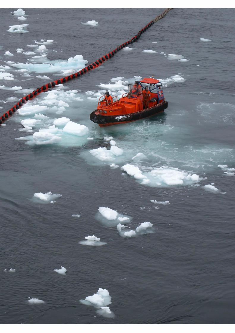
in the Arctic with and without ice (NPC, 2015). In the Baltic Sea for example, a brush/bucket skimmers
have successfully recovered a number of oil spills in winter shipping lanes as shown in Fig. 4.1 (Lampela,
2007). In 2011, Norwegian responders recovered 50% of 112 cubic metres of heavy fuel oil spilled into
freezing waters of Oslo fjord from the Godafoss container vessel (Bergstrøm, 2012).
At the time of the JIP’s conception, based on a significant body of research and field experience, any
future improvements in mechanical recovery systems in ice were expected as being evolutionary rather
than revolutionary. The JIP validated this opinion through a series of technology assessments (4.2).
2.2.2 In-situ Burning
At the outset of the JIP, in situ burning (ISB) in ice and Arctic environments was regarded as a safe,
environmentally acceptable and proven technique backed up by over five decades of research and
operational experience comprising hundreds of laboratory and basin experiments, numerous successful
Arctic field experiments, large-scale at-sea burns and the recent experience gained through the
Deepwater Horizon incident response. ISB was considered especially suited for use in the Arctic, where
ice often provides a natural barrier to maintain the necessary oil thicknesses for ignition without the need
for containment booms, and oil remains fresh and unemulsified for a longer period of time (compared to
the same oil in open water).
The first recorded use of ISB as an Arctic response countermeasure was in 1958 during a pipeline spill
in the Mackenzie River, Northwest Territories Canada. The United States Coast Guard (USCG) in
Alaska carried out important early experimental work with burning on sea ice in the 1970s (McMinn,
1972). A number of large-scale experiments successfully used ISB on oil that surfaced in spring melt
pools after being spilled beneath the ice and trapped through a full winter (NORCOR, 1975; Dickins and
Buist, 1981; Brandvik et al., 2006). Several projects successfully employed burning under field

11
conditions in close pack ice (over 90%) off the Canadian East Coast in 1986 and Norwegian Barents Sea
in 2009 (Buist and Dickins, 1987; Sørstrøm et al., 2010).
ISB was first used successfully offshore on a trial basis during the Exxon Valdez oil spill response (Allen,
1990). In 1993, a U.S. / Canada joint experiment, the Newfoundland Offshore Burn Experiment (NOBE)
successfully burned crude oil in fire-resistant booms in the open ocean and monitored a large suite of
environmental parameters, including smoke composition (carcinogens, Polycyclid Aromatic
Hydrocarbons (PAHs) etc.), residue toxicity, and upper water column impacts (Fingas et al., 1995).
Results demonstrated that when conducted in accord with established guidelines, ISB is safe and poses
no significant risk to human populations, wildlife or responders.
The massive ISB operation in response to the Deepwater Horizon incident provided a unique set of full-
scale operational data applicable to response planning for Arctic offshore areas in the summer. In this
first operational, sustained use of ISB offshore on a large scale, approximately 400 controlled burns
removed an estimated 220,000 to 310,000 barrels of oil from the Gulf of Mexico (Allen et al., 2011).
Numerous agencies, primarily in the United States, have established guidelines for the safe
implementation of ISB as a countermeasure. In 1994, the Alaska Regional Response Team (ARRT)
incorporated ISB guidelines for Alaska into its Unified Response Plan, becoming the first Arctic area to
formally consider ISB as an oil spill countermeasure. Their guidelines are still considered the most fully-
developed to date, and contain tables of safe distances for responders and the public under different
conditions (ARRT, 2008).
Experience with burning fresh, weathered, and emulsified oils and petroleum products in a range of ice
conditions in test tanks led to some basic “rules of thumb”. The most important parameter is the oil
thickness. In order to achieve 60-80% removal efficiency in most situations, the starting thickness of
crude oil needs to be on the order of 3-5 mm. (Buist et al., 2003). Depending on the ice coverage, this
thickness may not always occur naturally. In open to very open drift ice, tools such as herding agents
and fire resistant booms can significantly increase the thickness and provide for successful ignition and
efficient burning.
In previous Arctic field tests, burn removal rates for oil on ice ranged from 65% to well over 90%,
depending mainly on the size distribution of the oiled melt pools on ice. In an experimental spill under
solid ice in Norway in 2006, 3,400 litres of crude oil were allowed to surface naturally through the ice
and then burned with an overall removal efficiency of 96%. A portion of this oil was exposed to
weathering on the ice surface for over one month before being successfully ignited (Brandvik et al.,
2006). Similar high efficiencies were documented for ISB of oil mixed with ice contained within fire-
resistant booms during the 2009 SINTEF Oil in Ice Field Experiments (Potter and Buist, 2010).
In the same project, oil that was allowed to drift and weather in very close pack ice for over a week was
also successfully ignited and burned (Brandvik and Faksness, 2009).
Aerial ignition systems such as the Helitorch™ were used routinely for decades and are kept in inventory
by several Arctic response organizations as the primary airborne ignition tool, for example Alaska Clean
Seas, North Caspian Oil Company (NCOC) and Oil Spill Response Limited (OSRL) (Allen, 1987). This
system can ignite oil contained within a fireproof boom as demonstrated offshore during the
Newfoundland Offshore Burn Experiment (NOBE) project, or oil exposed on top the ice in thick enough
films. A major drawback in applying this strategy to sites far from shore is the decrease in helicopter
range caused by having to transit relatively slowly while carrying a sling load. A successful ground-
based proof of concept test programme sponsored by industry in Alaska in 2010 explored the feasibility
of igniting and ejecting gelled fuel at higher speeds than previously attempted (Preli et al., 2011). Further
work proposed, but not funded prior to the JIP, included examining the feasibility of developing an
operational system that the Federal Aviation Administration (FAA) and its European counterpart,
European Aviation Safety Agency (EASA) could approve. The JIP built on this past work by launching

12
a follow-on project (See 4.3.8).
Originally considered as a means of enhancing mechanical recovery of spills in the 1970s, the concept
of using herding agents to burn free-drifting oil slicks in open water or very open pack ice was
successfully field tested for the first time in the Norwegian Barents Sea in 2008 as part of a JIP on Oil
Spill Contingency for Arctic and Ice-Covered Waters (Buist et al., 2010). Burn removal effectiveness in
that test was estimated to be in the order of 90%. The residue floated readily and was recovered manually
from the water surface and ice edges. Buist et al. (2011) summarised past research into chemical herders
and concluded that oil spill responders should consider using them to enhance ISB in light to medium
ice concentrations. At the outset of the JIP, this promising new tool required further development to
refine the application and ignition delivery systems needed to achieve operational status. The
development of aerial delivery and ignition systems to facilitate herding and burning provided the
impetus for a series of JIP research projects (See 4.3.3 to 4.3.7).
2.2.3 Dispersant Application
At the outset of the JIP, knowledge gained from large-scale basin experiments and laboratory tests
showed that dispersants are effective in ice covered waters and that cold temperatures do not affect the
dispersibility of oils or their potential for biodegradation by indigenous Arctic microorganisms.
Chemical dispersants enhance natural dispersion by reducing the surface tension at the oil/water
interface, making it easier for waves to create small oil droplets (generally less than 100 microns) that
remain in suspension for long periods and are rapidly diluted in the water column to below toxicity
thresholds of concern. Studies show that oil-degrading microbes colonise the droplets within a few days
(MacNaughton et al., 2003; NRC 2005). Dispersed oil dilutes to concentrations in the parts per million
range within a few hours of effective dispersant application and to concentrations in the parts per billion
range in one or more days, depending upon the currents and wind dynamics (Lee et al., 2013).
Over the past two decades, a series of tank and basin tests and field experiments proved that cold
temperatures do not reduce the dispersibility of many oils or the activity of the dispersant. (Brandvik et
al., 1995; Brown and Goodman, 1996; Owens and Belore. 2004). Most oils remain dispersible until they
are cooled well below their “pour point” (the temperature at which the oil behaves like a semisolid).
Fortunately, the pour point for many Arctic crude oils is well below the freezing point of seawater
(Daling et al., 1990, Brandvik et al., 1995). In any event, the increase in viscosity related to cold
temperatures in the Arctic is not nearly as severe as the rapid increase in viscosity of oil affected by
evaporation and emulsification processes in open water.
Most importantly, research showed that the motion and interaction of broken ice pieces actually enhances
– rather than detracts from – the dispersion process by providing surface turbulence at higher levels than
would occur naturally with non-breaking waves in open water (Owens and Belore, 2004).
Studies found that dispersants are less toxic than both naturally dispersed and dispersant-treated oil
(NRC, 2005). Additional studies at the University of Alaska Fairbanks (UAF) demonstrated that three
Arctic marine species (two fish species and a copepod species) were no more sensitive to dispersed oil
than their counterparts in southern waters (Gardiner et al, 2013).
Experiments in a laboratory at Point Barrow, Alaska, completed close to the launch of the JIP,
demonstrated that indigenous Arctic microorganisms effectively degraded both fresh and weathered oil
regardless of whether it was dispersed naturally or with the addition of dispersants (McFarlin et al.,
2014). NRC (2014) concluded that naturally available levels of nutrients and oxygen could sustain
effective microbial degradation, in Arctic as well as temperate waters.

13
The SINTEF Oil in Ice JIP demonstrated the effectiveness of dispersants in a range of ice conditions in
meso-scale basin tests and field trials. As part of that project, a new controllable applicator arm was
developed to deliver dispersant more effectively to isolated oil pockets in the ice (Daling et al., 2010).
The advantages of using azimuthal stern drive (ASD) ice capable vessels or jet drives from small support
boats to add mechanical mixing energy to support oil dispersion were well known from basin tests in
Finland, and field tests in the Norwegian Barents Sea (Sørstrøm et al., 2010; Nedwed et al., 2006; Spring
et al., 2006; Daling et al., 2010). This additional energy source overcame the lack of natural turbulent
mixing energy present with minimal wave action in high ice concentrations. Lee et al. (2007) reported
on a field experiment showing how the addition of mineral fines with propeller wash in ice could disperse
of oil. Questions remained as to whether dispersed oil would resurface and coalesce under ice following
the initial dispersion and formed the impetus behind new JIP research in this area (See 4.4.1).
Aerial application of dispersants is a response strategy in common use in many areas of the world. This
tool has applications for incidents during the Arctic summer open water period and during periods of
open drift ice in non-freezing temperatures as long as there is sufficient wave action or mixing energy
introduced through the interaction of ice floes and cakes (2-20 m diameter). There are a variety of
platforms available from small single engine aircraft and helicopters nearshore to large four engine
airplanes like the C-130 (military) or L-100 (commercial variant) offshore. At the onset of the JIP, Oil
Spill Response Limited (OSRL) in the UK was in the process of certifying the first jet airplane (Boeing
727) specifically for dispersant application. In the U.S. a joint project by RVL and Waypoint was
working to certify the Boeing 737-400 to spray dispersants. Both of these programmes came to fruition
in 2016. A key advantage of moving towards jet-powered platforms is the much higher transit speed
(close to double the C-130), resulting in reduced response times (OGP and IPIECA 2012).
The Deepwater Horizon incident response demonstrated that large-scale subsea dispersant injection
(SSDI) could provide an effective response measure to mitigate the effects of a subsea release. A major
benefit of SSDI is the ability to continuously respond without being impacted by darkness, extreme
temperatures, strong winds, rough seas, or the presence of ice. This strategy can provide a much safer
working environment for well control personnel, keeping fresh oil from surfacing near the well site,
thereby reducing exposure to volatile aromatic components. Because of the high efficiency associated
with adding dispersant directly to fresh oil at the discharge point under highly turbulent conditions,
dispersant volumes are substantially reduced compared to a surface application. Recent studies by API
in this area recommend a dispersant to oil ratio for SSDI of 1:100 (Nedwed, 2017).
It is important to recognise that while surface conditions in the Arctic are seasonally different from other
more temperate regions in terms of presence of ice, conditions subsea are essentially the same as
elsewhere. For example water temperatures at depth in the Gulf of Mexico approach within a few degrees
of temperatures in the lower water column in the Arctic. In this regard, recent and ongoing results other
SSDI research and engineering studies (e.g. API – see Section 1.1) are largely applicable to Arctic regions
as well.
Laboratory experiments in vertical tanks demonstrated the generation of small-dispersed oil droplets
through dispersant injection at the point of oil release. (Brandvik et al., 2013; Johansen et al., 2013).
NRC (2014) concluded that more work was needed to understand the effectiveness, systems design, and
short-and long-term impacts of subsea dispersant delivery in Arctic waters (NRC, 2014). The JIP
commissioned a new project to look at certain aspects of using SSDI (film thickness, percentage
resurfacing etc.) at different water depths (See 4.4.3).
Chapter 4.4 discusses all of the JIP project results in this area, focusing on better defining windows of
opportunity for dispersants in ice and evaluating the potential for resurfacing with and without
mechanical mixing energy.

14
2.2.4 Detection and Mapping including Remote Sensing
At the outset of the JIP, the state of knowledge regarding remote sensing in ice reflected a lack of hard
data to confirm theoretical assumptions about the performance of most sensors in a particular oil-in-ice
scenario (e.g.: Dickins and Andersen, 2009; Fingas and Brown, 2011). Overall conclusions from limited
experience were that while many existing airborne systems would likely have a high potential for
detecting and mapping large spills in very open ice covers, they may have less potential as the ice
concentration increases. It was clear that more work was needed to evaluate different sensors in actual
oil in ice situations.
In order to mount an effective response it is critical to know where spilled oil is at any given time and
ideally the distribution of film thickness to effectively allocate valuable airborne and marine response
assets. This requires accurate, near real time reconnaissance presented in graphical and digital map
products that are easily accessible and useable by responders in the field and decision makers in the
Command Centre.
Much of the early research on spill detection in ice took place over a ten-year period beginning in the
late 1970s, motivated by offshore drilling programmes in the Canadian Beaufort Sea. Researchers
carried out analytical, bench, and basin tests and field trials using a wide range of sensor types—
acoustics, radar, ultraviolet fluorescence, infrared (IR), gamma ray, microwave radiometer, resonance
scattering, gas sniffers, and airborne and ground-based penetrating radar (GPR). (e.g., Dickins, 2000;
Goodman, 2008; Fingas and Brown, 2011).
Knowledge of which sensors were most likely to succeed in different oil in ice scenarios was extrapolated
largely from experiences with temperate spills (e.g., Leifer et al., 2012) supported by a small number of
field tests and tank/basin experiments with small-scale spills in ice.
The previous SINTEF Oil in Ice JIP (Dickins and Anderson, 2009; Sørstrøm et al., 2010) summarised
the state of the art for remote sensing of oil in ice with these points:
A mix of conventional airborne sensors in current use was likely to prove effective with spills
in relatively open ice cover (1-4/10).
The use of existing remote sensing systems to detect spills contained in closely packed ice
was still largely unknown.
The detection of oil underneath and trapped within the ice remained a major challenge.
Future platforms would likely include both Unmanned Aircraft Systems (UAS) and
Autonomous Underwater Vehicles (AUVs) carrying a suite of sensors.
Trained human observers remained an essential element of any surveillance programme, and
the best means of avoiding or reducing the number of false positives.
It was clear that no single technology or sensor package could detect oil in ice under all conditions.
Certain sensors could potentially detect oil in or on or among ice under particular conditions (oil layer
thickness, ice thickness, ice temperature etc.) but all systems had known limitations related to low
visibility, cloud cover, sea state (too calm or too rough) and rough deformed ice. Many sensor
technologies showed promise, but more research was needed to confirm their capabilities in responding
to different oil in ice situations.
The following brief summaries represent the state of knowledge for a number of key sensors and
platforms at the conclusion of the SINTEF Oil in Ice JIP in 2010 and corresponding closely to the
understanding at the outset of the Arctic Oil Spill Response Technology JIP in 2012.
Radar: Ground Penetrating Radar (GPR) was the only sensor where tests had demonstrated its
ability to detect oil trapped beneath or within a solid ice sheet. Drawbacks were the difficulty
in interpreting the results, requirement for smooth ice and need to work safely from the ice

15
surface (Dickins et al., 2008). In 2008, the same GPR suspended beneath a helicopter traveling
at speeds up to 20 knots and altitudes up to 20 m successfully detected a thin layer of crude oil
buried under hard-packed snow during field tests on Svalbard (Bradford et al., 2010). A
prototype frequency-modulated continuous-wave (FMCW) radar designed to detect oil trapped
under solid ice from a low-flying helicopter was developed and tested in 2011-2012 through a
series of joint government and industry projects, but confirmation of its capabilities was still
lacking at the outset of the JIP.
There was consideration to utilise nuclear magnetic resonance (NMR) as a potential new
airborne system to detect oil trapped under or in ice (Palandro et al., 2013). A full-scale
prototype system was under evaluation at the outset of the JIP in 2012 and a field test of a
helicopter-mounted system was in the planning stages (subsequently completed in
Newfoundland in 2016).
Infrared Systems: Infrared (IR) systems are a primary sensor used worldwide for detecting oil
slicks at sea from low-flying aircraft and surface vessels. This technology was considered to
have potential for oil in ice applications because oil among or on ice absorbs solar radiation and
heats up faster than its surroundings (Norcor, 1975). Airborne IR sensors are used operationally
in Alaska for spills on land. An earlier release of oil in pack ice in Norway in 1993 demonstrated
that a simple IR video camera in a helicopter clearly detected warm oil being pumped by hose
over colder ice and then into the water between floes (Singsaas et al., 1994). Multi-spectral and
thermal IR cameras were used successfully to detect, map and estimate thickness of slicks
during the Deepwater Horizon incident (Leifer et al., 2012). However, research data needed to
fully assess the capabilities of IR for detecting spills on and among ice was lacking.
Ship-based IR sensors were considered to have applications in specific situations involving oil
between floes in pack ice (Dickins and Andersen, 2009). Systems that integrate high resolution
Forward Looking IR and low light video were deployed on several Norwegian and U.S. offshore
response vessels but remained untested with spills in ice.
Dogs: Contingent on safety (e.g., ice floe size, thickness, stability) trained dogs with their
handlers on the ice can track and locate even very small oil spills buried under snow from long
distances. For example, in trials on Svalbard in 2008 dogs successfully detected a small quantity
of oil buried under snow on the ice surface from a downwind distance of 5 km (Brandvik and
Buvik, 2009).
Autonomous Underwater Vehicles (AUVs) and Unmanned Aircraft Systems (UAS): Field trials
off NE Greenland more than a decade ago demonstrated the ability of AUVs to carry sensor
packages over long distances beneath sea ice. (Wadhams et al., 2006). More recently, in 2012,
single and multi-beam sonar sensors successfully detected and mapped the boundaries and
thickness of oil spilled under ice in a basin test at the U.S. Army Cold Regions Research and
Engineering Laboratory (CRREL) (Wilkinson et al., 2012/13). Known drawbacks with using
underwater AUVs to look for oil under included: relatively slow survey speed (compared to
aerial platforms), inability to transmit large volumes of real time data such as imagery to the
surface, and positioning under moving ice. Proven ROV technology avoids the data
transmission and positioning issues but at the cost of being tied to the mother ship by an
umbilical, severely limiting the survey range.
UAS technology was in its infancy at the outset of the JIP. Groups in Alaska and elsewhere
were considering UAS as potential future surveillance platforms in Polar Regions. For example,
beginning in 2013, the United States Coast Guard incorporated UAS tests as a key element in
their annual “Arctic Shield” deployment exercises to develop response strategies and logistics
platforms for the Alaskan offshore: (https://www.uscg.mil/acquisition/newsroom/updates/rdc080913.asp)

16
Dedicated Pollution Surveillance Aircraft: Arctic nations such as Canada, Iceland, Finland,
Denmark, Norway, and Sweden all operate dedicated pollution surveillance aircraft. The sensor
suite on-board these aircraft was selected on the basis of known capabilities in open water
pollution surveillance. Little or no data was available to determine individual airborne sensor
capabilities or operating windows in responding to a spill in ice.
JIP remote sensing projects focused on acquiring the data needed to evaluate the capabilities of different
sensors to detect and map oil under, in, and on ice and synthesizing the available information in a form
that is useful to responders at an operational level (Chapter 4.5).
2.2.5 Trajectory Modelling
Sea ice models in use at the outset of the JIP (2012) were primarily aimed at providing necessary hindcast
predictions for environmental impact assessments prior to drilling. They were not optimised for
simulating sea ice dynamics at the high spatial and temporal resolutions required for operational
response. At the same time, the available oil spill fate and behaviour models were unable to efficiently
access or use state of the art ice model input data. As a result, the operational capability to predict realistic
or accurate oil spill movements in a range of ice conditions was limited.
Observations of oil spill movements from accidental releases date back to the beginning of marine
transport of oil in the late 19th century. Initially, oil slick movements were plotted on shipping charts.
Over time, early observers determined that magnitude and direction of the winds and currents combine
to transport oil at the water’s surface. Through the addition of wind and current information acting on
the slick, the first predictions of future oil movement were developed and oil spill modelling began.
Comprehensive tracking and long-term monitoring of oil released in ice requires assimilating field data,
plotting real-time observations, and integrating this information with forecasting tools such as weather
models, ice drift algorithms, and oil spreading and weathering models.
The oil industry and government agencies have used computer-based oil spill models for over 30 years
to: support environmental assessments at the permitting stage, develop Oil Spill Response Plans
(OSRPs), and predict the movement of accidental spills in open water. The models simulate oil transport
and predict the changes the oil undergoes as it interacts with water, air, and land. These models simulate
spill events using the best available characterization of the wind, and hydrodynamic forces (currents)
forces that drive oil transport. The models also identify the potential consequences from a spill (e.g.
relative probability of oiling specific shoreline areas). This information can then be used to guide
response planning and prioritise response asset deployment.
Weathering and spreading of oil in the presence of ice is significantly different from those processes in
more temperate waters. Weathering of oil under Arctic conditions was studied extensively in the most
recent SINTEF JIP and several other comprehensive research efforts in Norway and the U.S. (Buist et
al., 2009; Brandvik and Faksness, 2009; Sørstrøm et al., 2010). This extensive knowledge base on oil
fate and behaviour in ice is incorporated in commercially available models such as OSCAR and OILMAP
in common use.
The current generation of oil spill models could predict the behaviour of oil and its likely weathering fate
in ice environments (e.g. degree of evaporation, rate of emulsification, etc.), but at the outset of the JIP
in 2012, they had limited capabilities to realistically model close to real time oil movements in the
presence of a significant ice cover during an actual response. This deficiency was largely the result of
limited resolution offered by the existing ice models and the inability of the commonly used oil spill
models to efficiently import and utilise outputs from the ice models.

17
Commercially available ice-strengthened Global Positioning System (GPS) beacons and buoys had, for
many years, been tracking ice movements during an entire winter season throughout the polar basin (See
International Arctic Buoy Program at http://iabp.apl.washington.edu/). Tracking oil spills accurately in
a moving ice cover involves deploying beacons at regular intervals on the ice as oil moves away from
the spill source. These beacon positions can then be used to direct air and marine responders toward the
spill. Ice effectively traps the oil and maintains it within a relatively small contaminated area. Beacons
placed on or among oiled ice with ice coverage equal to or greater than 60% will effectively track the
oiled ice motion. Closely spaced GPS beacons can also follow the evolving pattern of spill fragmentation
and divergence as the pack expands and contracts. This was demonstrated by following an accidental
shipping spill in ice in the Baltic (Hirvi et al., 1987). By using the buoy positions to reinitialise the spill
trajectory models, the prediction accuracy is greatly improved.
Oil spill trajectory models running at low and mid-latitudes use information about ocean currents, winds
and waves to predict where the oil is likely to drift. The presence of sea ice and especially its percent
coverage drastically changes how an oil spill spreads locally among the floes and how it moves regionally
and in what proportion to the ice drift velocity. Given this close link between the oil and ice movements,
understanding and correctly modelling ice dynamics was viewed a prerequisite for producing better oil
spill predictions, both on the short and mid-term. The failure of existing ice drift models to reproduce the
short and mid-term evolution of the ice focused JIP research in this area on improving the ice models as
a prerequisite to expanding the ability to more reliably predict oil in ice drift in an actual response
(Rampal et al., 2009). JIP work in this area is described in Section 4.6.
2.2.6 Environmental Effects – NEBA
Net Environmental Benefit Analysis (NEBA) is a process tool that formalises the evaluation and
comparison of the expected response effectiveness versus the potential environmental impacts of the oil
spill, as well as impacts from response activities (vessels, aircraft, waste disposal etc.). Knowledge of the
biology and ecology of the specific region is key to the application of a NEBA in a meaningful and
rigorous manner.
The optimal spill response technique is defined as the one that minimises the potential adverse effect(s)
of a spill on the habitat of the region and its biological resources. Responders also need to be mindful
that the subsistence lifestyle in the Arctic is inextricably linked to the ecological condition of the natural
resources as well as the traditional cultural practices of Arctic residents and that these issues need to be
considered in parallel with the NEBA.
The output from the NEBA process is the selection of response technique(s) that minimise the overall
impacts of a potential spill on the environment, and promote the most rapid recovery and restoration of
the affected area (IPIECA/IOGP, 2015). The NEBA process provides a strategy for decision makers to
select appropriate response options at a specific spill location based on the analysis of environmental
trade-offs that may occur from the use of the various oil spill countermeasures available.
From an ecological point of view, a NEBA provides a protocol for weighing the advantages and
disadvantages of various spill responses with regard to flora and fauna and their habitats within the
specific area of concern, compared with no response (also referred to as natural attenuation). The process
also provides a cross comparison of the net environmental benefits of each possible response option, for
example, comparing mechanical recovery with dispersants and/or burning.
All oil spill response tools should be considered and should have the potential for use if supported by a
positive NEBA result. The final decision on OSR strategies should be based on robust environmental
considerations, including consideration of knowledge gaps. Ideally, there should be no one-default
response option. Responders and decision makers should have the flexibility to choose a particular
response strategy or combination of strategies based on the results of a NEBA, reflecting the spill
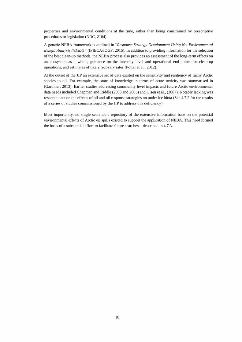
18
properties and environmental conditions at the time, rather than being constrained by prescriptive
procedures or legislation (NRC, 2104)
A generic NEBA framework is outlined in “Response Strategy Development Using Net Environmental
Benefit Analysis (NEBA)” (IPIECA/IOGP, 2015). In addition to providing information for the selection
of the best clean-up methods, the NEBA process also provides an assessment of the long-term effects on
an ecosystem as a whole, guidance on the intensity level and operational end-points for clean-up
operations, and estimates of likely recovery rates (Potter et al., 2012).
At the outset of the JIP an extensive set of data existed on the sensitivity and resiliency of many Arctic
species to oil. For example, the state of knowledge in terms of acute toxicity was summarised in
(Gardiner, 2013). Earlier studies addressing community level impacts and future Arctic environmental
data needs included Chapman and Riddle (2003 and 2005) and Olsen et al., (2007). Notably lacking was
research data on the effects of oil and oil response strategies on under ice biota (See 4.7.2 for the results
of a series of studies commissioned by the JIP to address this deficiency).
Most importantly, no single searchable repository of the extensive information base on the potential
environmental effects of Arctic oil spills existed to support the application of NEBA. This need formed
the basis of a substantial effort to facilitate future searches – described in 4.7.3.

19
Photo: D. Dickins during the 2009 SINTEF Oil in Ice JIP field programme.


21
3 JIP SCOPE AND APPROACH
The ultimate goal of this JIP was to build additional confidence in the available response tools and to
extend their capabilities with new strategies, systems and a better understanding of operating windows
when a given response tool is likely to be effective. Specific objectives of the JIP were to:
Improve capabilities in many aspects of Arctic spill response.
Develop the knowledge base needed to better assess the net environmental benefits of different
response options.
Prove the viability of existing OSR technologies in the Arctic and determine their operating
boundaries based on environmental conditions and the need for responder safety.
Develop new OSR technologies for the Arctic.
Disseminate information on best practices for Arctic response to a wide range of stakeholders
(regulators, responders, indigenous peoples, informed public, and responders).
These objectives and their outcomes serve a cross section of industry, government and public interests:
1) At a planning and assessment level to enhance the quality and standard of oil spill response
contingency plans submitted as part of future drilling permit applications;
2) At a tactical response operations management level to support informed decision-making within the
incident command structure, resulting in the selection of more effective and environmentally
beneficial response strategies; and
3) At a field response operations level to provide new and improved response “tools”, expanding the
options available to responders to deal with a broad range of environmental conditions and spill
scenarios.
This Chapter describes how the JIP research scope was based on identifying opportunities for
improvement, and describes the systematic way in which the JIP developed a series of 34 research
projects to come up with answers to priority issues (listed in 3.4). Chapter 4 presents the JIP results and
demonstrates their response applicability at both the tactical and field operations levels. Chapter 5
discusses how the research results support a greater understanding of all aspects of Arctic spill response,
while increasing confidence in capabilities to deal with a major incident in a wide range of different
conditions.
The JIP research programme focused on priority areas where new research and technology development
had the best chance of significantly advancing capabilities to respond to marine spills in the presence of
ice in the near future. Research areas were chosen to encompass all the key elements of an integrated
offshore response system, including the three main response tools and the important support functions of
tracking and detection and using NEBA to guide response decision-making and minimise any potential
environmental impacts.
One important aspect of Arctic spill response that is not covered under this JIP is shoreline protection
and response. This was due to the breadth of topics involved. Methods and strategies available to recover
oil from Arctic shorelines are covered in detail in EPPR (2015 and 2017 – in press).
Experienced engineers and scientists from each of the member companies developed and steered the
individual research programmes in the different areas (See Fig. 3.1). Opportunities to validate laboratory
and basin test results through field research were sought to support different research areas
(Environmental Effects, Dispersants and ISB).

22
Figure 3.1 Complementary structure and scientific basis of the six JIP Research Areas.
A worldwide network of recognised experts in the different disciplines such as chemistry, toxicology,
marine biology, oceanography, engineering, and sensor design, were contracted to carry out the research.
Their work produced new information technology tools, response systems, models and scientific data on
important topics like operability windows, toxicity and effectiveness. Global expertise included 39
contractors in ten countries – Canada, U.S.A, Norway, Denmark, Finland, UK, Germany, France,
Netherlands, and Israel (Fig. 3.2).
Figure 3.2 Worldwide engagement of Arctic oil spill response specialists.

23
3.1 Questions the JIP set out to answer
An overall assessment of the state-of-the-art with respect to Arctic spill response commissioned jointly
by API and IOGP prior to initiating the JIP helped guide the technical managers within the different
companies in designing and executing the research projects (Potter et al., 2012). To best address scientific
and engineering areas where significant advances were possible within the five-year JIP time frame and
available budget, the following questions were posed:
1. Mechanical recovery of large spills in ice is constrained by the low encounter rate and ice
interference with skimmer and boom performance. Are there any new concepts that can yield
significant improvements in recovery to justify new research programmes and substantial JIP budget
allocations in this area?
2. Laboratory, basin and field trials have proven the potentially high effectiveness of dispersants in a
range of ice conditions. There are some concerns about the long-term effectiveness of dispersing oil
in ice with low energy levels possibly leading to resurfacing under the ice. What new data do we
need to collect to better define the likely window of effectiveness for dispersants in ice?
3. Burning oiled melt pools on top of the ice in the spring is a response strategy that operators originally
suggested in drilling permit applications dating back to 1990 and earlier. At present, the only
available, proven aerial ignition system – the Helitorch™ - must either be operated off a nearby
support vessel or fly out from a shore base as a sling load at relatively slow speed, resulting in limited
range and endurance on site. How can the JIP develop a new system that overcomes these limitations
while providing a safer alternative to existing technologies?
4. Herders are viewed as a promising future response tool that enables uncontained in-situ burning in
a range of conditions from open drift ice to open water. What further work is needed to prove their
environmental acceptability and effectiveness in full-scale operational setting?
5. The only previous field-test involving herding and burning relied on small boats to apply the herder
and initiate the ignition. How can we develop a rapid response aerial delivery system that could herd
and burn slicks in a remote area without having to rely on marine support?
6. Detecting and mapping oil in the presence of significant ice cover is an area with limited real-world
data applicable to an Arctic scenario. Which sensors and platforms demonstrate the most promise to
justify being recommended as part of future surveillance systems to support Arctic offshore drilling
and what are their limitations and capabilities in different situations of oil in ice?
7. Existing oil spill trajectory models are focused on spills in open water and do not account for the
presence of ice in a realistic way or with sufficient spatial resolution to be of great value
operationally. How can we improve the existing modelling capabilities to account for the presence
of different types of ice covers and to improve the prediction accuracy?
8. NEBA is recognised within the worldwide oil spill response community as the best scientifically
supportable means of assessing the relative net benefits of utilising a particular spill response
countermeasure in different situations. How can the JIP facilitate the application of NEBA in an
Arctic environment?
9. Over the past four decades, hundreds of research projects were carried out covering a wide range of
environmental issues related to the topic of oil spills in ice. How can the JIP assimilate this vast
historical knowledge base and make it available to all stakeholders with an interest in promoting
safe, responsible Arctic offshore development in the future?
These and other questions defined the suite of priority research objectives at the JIP outset, but the agenda
was also designed to accommodate new data and ideas and introduce new research projects as the
programme evolved. Examples of how this flexibility led to more successful, targeted research results
are outlined below:
Based on results from large-scale outdoor basin tests in Alaska, it became apparent that a new
integrated system was needed that applied the herder and ignited the oil on a single flight. This led

24
to a new project in year three of the JIP to design, build, static test and flight test a practical integrated
system capable of being mounted on a wide range of helicopters worldwide. (4.3.6)
The Phase 1 state of knowledge reports on remote sensing in ice led to an ambitious, unique research
program to compare different sensors in a controlled oil and ice test basin environment (Phase 2).
Results from these basin tests then led to two new remote sensing projects launched in the last six
months of the JIP to further assess the capabilities of infrared and radar sensors, two areas where it
became apparent that more data was needed. (4.5.3)
Openness to sharing opportunities as they arose through the course of the JIP was evidenced in the
acceptance of an invitation to participate in the Spring 2016 NOFO Oil on Water exercise in the
Norwegian North Sea. The JIP secured the services of experienced contractors in a timely fashion
to use this opportunity to test herders and burning in an open ocean environment for the first time
(4.3.7).
Wherever possible, the JIP looked for opportunities to undertake field studies to collect new data and
validate new response strategies at a larger scale than is possible in laboratory or basin environments.
As a result, successful programs in Alaska (Fairbanks) and Norway (North Sea and Svalbard) supported
research in key areas of burning, dispersants, and environmental effects.
The JIP projects successfully addressed all of the previous guiding questions in addition to others that
arose over the course of the programme (3.2 below).
3.2 Project Selection
The following criteria were applied to refine the JIP project list:
Need: Assessed in terms of what constituted “success” in the context of advancing Arctic spill
response capability. Success was interpreted in different ways such as: improving the knowledge
base to improve planning, regulatory acceptance and response decision-making; and developing
new and/or enhanced strategies and technologies to provide more effective response tools.
Operational and regulatory relevance: Emphasising Arctic technologies where new research
carried out by the JIP could facilitate acceptance of proven and/or evolving technologies by
regulators and operators. Examples are dispersants in ice and herding agents used in conjunction
with burning.
Geographic relevance: With few exceptions, projects were designed to have both pan-Arctic and
subarctic applicability – focusing on areas where future drilling and production could encounter ice
for all or part of the year, but also recognising that for the foreseeable future, many exploration
programmes will take place during periods characterised by open water. The field trials with herders
in open water (4.3.7) are an example where the JIP results apply to oil spill response in temperate
as well as Arctic waters. Examples of research with geographic specificity included the need to look
at dispersant and herder effectiveness in low salinity water, as found in the north Caspian Sea and
Arctic areas close to large river deltas such as at the mouths of the Colville, Mackenzie and Lena
Rivers, in the U.S.A, Canada and Russia respectively.
Timing: The research timeline needed to fit the five-year JIP horizon or at least result in significant
progress towards an achievable goal within this period.
Technical Feasibility: This criterion considered the technical feasibility of carrying out the project
successfully in terms of developing and executing the research project with the resources available,
e.g. laboratories, tanks and basins and approved field test sites.
Budget: The suite of projects within each research area needed to fit within broad budgetary
constraints. Initial allocations at the outset of the project shifted somewhat as research results gave
rise to new priorities and ideas.

25
Expertise: The availability of capable contractors to perform the work was a consideration
throughout the procurement process. In such a specialised research field as Arctic spill response,
there are a limited number of experienced scientists and engineers with the necessary background
to perform the work at the high level of competency required. Most of the work was undertaken
through competitive bid with a standardised procedure for proposal review and ranking.
To satisfy these criteria and answer the guiding questions posed in Section 3.1, over the course of a five-
year programme 2012 to 2017, the JIP developed and carried out a series of advanced research and
development projects applicable to six fundamental elements of any spill response:
Mechanical recovery
Explore the feasibility of developing new mechanical recovery concepts that could
significantly improve on the capabilities of existing systems
In situ burning
Build upon an already established Arctic response strategy and expand the windows of
opportunity for its use by combining burning with herding agents.
Dispersants
Acquire new data to validate and expand the understanding of surface and subsea
dispersant effectiveness in a variety of ice conditions as well as their potential
environmental effects.
Trajectory modelling
Develop improved, higher resolution modelling techniques for predicting the
movement of oil spills in ice.
Remote sensing
Assess the capabilities of different under-ice and above-ice sensors in detecting and
mapping oil spills in ice.
Environmental effects
Create an information support tool to assist in applying NEBA (also referred to as
SIMA) to future Arctic spill scenarios and collect new environmental effects data.
The JIP focused on the challenges of dealing with an accidental spill in ice recognising that a number of
other major joint research initiatives were underway or were recently completed in the UK, the U.S.A.
and Norway with the goal of improving spill response in open water (1.1). Many of the results from these
programmes are complementary to this JIP and can be used to guide planning and response to open water
spills in the Arctic.For example, subsea dispersant injection represents a key research area where
knowledge transfer from the API’s open water research programme could greatly assist future Arctic
response planning. A prime example of transfer in the other direction involves the JIP’s validation of
herding and burning as a viable response option for open water as well as areas with ice (see results from
the NOFO Oil on Water Trial in 4.3.7).
The JIP research applies to a wide range of conditions including: open water, mobile pack ice in the
Arctic Basin, seasonal ice in the Marginal Ice Zone (MIZ), fast ice nearshore and brackish lower salinity
ice. Many of the JIPs projects have direct applicability to ice conditions representative of the MIZ as well
as open water, and this is pointed out in the discussion of results to follow in Chapter 4.
Scenarios played a part in defining the scope of many projects but the research programme as a whole
was not specifically “scenario driven”. In general, the focus of the overall research scope was on
exploration and production related incidents with an emphasis on dealing with larger spills. However,
many of the results are also directly applicable to range of small to moderate spills (tens to hundreds of
barrels) as well as shipping incidents.

26
3.3 JIP Research Methods
Research projects used established protocols and proven scientific technologies. Table 3.1 shows how
the JIP used a combination of scientific reviews, different test scales, modelling and engineering studies
within each research area to collect new experimental and field data, and apply the results to creating
new and improved oil spill response technologies and strategies.
Table 3.1 JIP Research Methods
Experimental practices used recognised test standards (e.g. ASTM) and protocols. Test matrices were
designed to cover a broad range of parameters that would provide for the widest possible application of
results to different operational scenarios (e.g. turbulent mixing energy, oil type, oil weathering, ice
concentration, oil film thickness). Completing the large number of individual test runs across different
experiments, as required for the dispersant effectiveness testing, required the use of laboratories and
flume tanks/basins in four different countries (Canada, UK, France, and Norway). This required careful
inter-basin calibration tests to ensure that the results from different institutions were consistent and
comparable (Faksness et al., 2014).
Experiments and field tests used a range of oil types from light to heavy crude oils as detailed in Table
3.1 and Figure 3.3.
Figure 3.3 Range of Oil Types used in JIP Experiments
ARCTIC RESPONSE TECHNOLOGY JIP
OIL RANGE FOR EXPERIMENTS
ART JIP - Total – P. Blanc – November 29, 2016 3
Dispersants (lab/tank)
ISB / Herders (lab)
ISB / Herders (field)
Envt Effects (mesocosms)
Remote Sensing (basin)
10 20 30 40 50
API gravity
Heavy crudes Medium oils Light oils Condensates

27
Dispersant testing at multiple locations represented the broadest range of oil types, while the field tests
and multi-sensor basin test were necessarily limited to single oils in each case as shown below in Table
3.2. While the remote sensing basin testing used a single crude oil type, the results are generally
applicable to a wide range of oils.
Table 3.2 Oil Matrix for JIP Experiments
3.4 JIP Projects
The full extent of the JIP programme included 34 research projects grouped below by study area. In some
cases, a single topic area resulted in several reports or several topic areas formed a single unified final
report. Project names shown here are deliberately descriptive in order to outline the JIP research topics
“at a glance”. They are not intended to exactly match the final report titles. Chapter 7 provides a full
listing of technical reports, conference papers and peer reviewed journal articles covering the different
JIP research project areas:
Mechanical Recovery
• Summary Report
In Situ Burning (ISB)
• State of knowledge
• Technology summary and lessons from key experiments
• Status of regulation in Arctic and subarctic countries
• Research summary: herding surfactants to contract and thicken oil spills for ISB in Arctic waters
• Historical review and date of the art for oil Slick ignition for ISB
• Field research on helicopter application of chemical herders to advance ISB
• Develop and test Integrated herder/igniter delivery system for helicopters
• Conceptual design of long range aerial ignition system
• NOFO Oil on Water 2016 field exercise – validate use of herders and burning in open water

28
Dispersants
• Status of regulations and outreach opportunities
• Fate of dispersed oil under ice
• Field study to collect under-ice turbulence data (Svea, Svalbard)
• Flume tank experiments
• Dispersed oil fate model
• Propeller wash turbulence mixing model
• Dispersant effectiveness testing under realistic conditions
• Modelling subsea dispersant injection
• Evaluating dispersant effectiveness boundaries
• Oil and dispersant ice core analysis
• Peer-reviewed papers on dispersant effects on fish populations
• Biodegradation of dispersants in sea water
• Development of manuscript on dispersant use
Remote Sensing
• State of knowledge Reviews: surface & subsea remote sensing
• Basin tests: above and below ice sensor comparison & modelling
• Basin tests: infrared sensor capabilities to detect oil on ice
• Basin tests: FMCW radar to assess capabilities for airborne detection of oil under ice
• Guide for oil spill detection in ice covered waters
Trajectory Modelling
• Sea ice model developments to improve oil spill forecasting
• Improved ice trajectory models and validation with drifter data
• New ice models integrated with existing oil fate and behaviour models
Environmental Effects
• Environmental effects of arctic oil spills and arctic spill response technologies
• Web-based NEBA support tool – literature database and information portal
• Unique Arctic communities (field mesocosms & laboratory studies)
o Oil biodegradation and persistence
o Resilience and sensitivity

29
Preparations for the NOFO Oil on Water Exercise 2016 Photo: D. Dickins

22
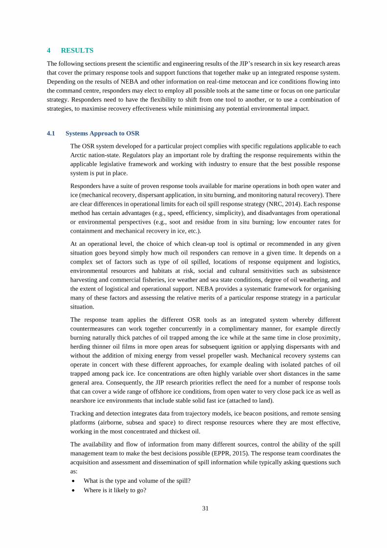
31
4 RESULTS
The following sections present the scientific and engineering results of the JIP’s research in six key research areas
that cover the primary response tools and support functions that together make up an integrated response system.
Depending on the results of NEBA and other information on real-time metocean and ice conditions flowing into
the command centre, responders may elect to employ all possible tools at the same time or focus on one particular
strategy. Responders need to have the flexibility to shift from one tool to another, or to use a combination of
strategies, to maximise recovery effectiveness while minimising any potential environmental impact.
4.1 Systems Approach to OSR
The OSR system developed for a particular project complies with specific regulations applicable to each
Arctic nation-state. Regulators play an important role by drafting the response requirements within the
applicable legislative framework and working with industry to ensure that the best possible response
system is put in place.
Responders have a suite of proven response tools available for marine operations in both open water and
ice (mechanical recovery, dispersant application, in situ burning, and monitoring natural recovery). There
are clear differences in operational limits for each oil spill response strategy (NRC, 2014). Each response
method has certain advantages (e.g., speed, efficiency, simplicity), and disadvantages from operational
or environmental perspectives (e.g., soot and residue from in situ burning; low encounter rates for
containment and mechanical recovery in ice, etc.).
At an operational level, the choice of which clean-up tool is optimal or recommended in any given
situation goes beyond simply how much oil responders can remove in a given time. It depends on a
complex set of factors such as type of oil spilled, locations of response equipment and logistics,
environmental resources and habitats at risk, social and cultural sensitivities such as subsistence
harvesting and commercial fisheries, ice weather and sea state conditions, degree of oil weathering, and
the extent of logistical and operational support. NEBA provides a systematic framework for organising
many of these factors and assessing the relative merits of a particular response strategy in a particular
situation.
The response team applies the different OSR tools as an integrated system whereby different
countermeasures can work together concurrently in a complimentary manner, for example directly
burning naturally thick patches of oil trapped among the ice while at the same time in close proximity,
herding thinner oil films in more open areas for subsequent ignition or applying dispersants with and
without the addition of mixing energy from vessel propeller wash. Mechanical recovery systems can
operate in concert with these different approaches, for example dealing with isolated patches of oil
trapped among pack ice. Ice concentrations are often highly variable over short distances in the same
general area. Consequently, the JIP research priorities reflect the need for a number of response tools
that can cover a wide range of offshore ice conditions, from open water to very close pack ice as well as
nearshore ice environments that include stable solid fast ice (attached to land).
Tracking and detection integrates data from trajectory models, ice beacon positions, and remote sensing
platforms (airborne, subsea and space) to direct response resources where they are most effective,
working in the most concentrated and thickest oil.
The availability and flow of information from many different sources, control the ability of the spill
management team to make the best decisions possible (EPPR, 2015). The response team coordinates the
acquisition and assessment and dissemination of spill information while typically asking questions such
as:
What is the type and volume of the spill?
Where is it likely to go?

32
How is the oil behaving and how will it change through weathering and spreading?
What are the resources at risk in the spill path, what are their sensitivity and vulnerability?
What are the most feasible and environmentally acceptable response options under the conditions
prevailing at the time?
In an environment with static ice and snow conditions (e.g. fast ice nearshore), the response timelines
can extend for many months if the oil is naturally contained, concentrated, and trapped for long periods
in the ice. In more dynamic ice conditions offshore, the decision process must adapt to deal with predicted
(trajectory models) and monitored (tracking buoys/overflights) oil in ice positions. Regardless, the
presence of a significant ice cover slows or in many cases stops oil from spreading, naturally contains oil
in thicker films that are more amenable to burning for example, slows weathering processes (thereby
expanding the windows of opportunity for tools like dispersant application). When oil is frozen into the
surface or encapsulated within the ice sheet it remains isolated from contacting key marine resources for
extended periods of time. These and other differences between responses in an Arctic vs. temperate
environment are summarised in 5.1
Most importantly, in terms of all aspects of spill response, the natural containment provided by the ice
generally buys time, allowing responders to wait for better metocean conditions or plan months ahead in
some cases (e.g. a spring response to a winter spill after the oil surfaces naturally through the ice).
Compared to a spill in open water, oil in ice is not spreading to any great extent or moving very quickly.
Decisions that have a time window of hours in an open water response can now extend over days, weeks
and even months depending on the situation and location (EPPR, 2015).
The decision process in any spill response typically involves the assessment of constantly changing
information and data to develop and continuously update objectives and strategies. NEBA plays a key
part in this process by providing a systematic framework for evaluating the relative benefits of different
response options, including natural attenuation.
While the following sections necessarily discuss the research projects by area of study, the operational
reality is that no one response tool or supporting activity is ever viewed in isolation in an actual response.
Responders may deploy multiple tools in close proximity depending on local conditions. Modelling oil
fate and behaviour while tracking and monitoring oil and ice as they drift forms an integrated picture that
informs the command centre in a near real-time data stream.
4.2 Mechanical Recovery
At the outset of the JIP, future improvements in mechanical recovery systems in ice were expected as
being evolutionary rather than revolutionary (2.2.1). In order to confirm the validity of this expectation,
the JIP aimed to think outside the box and explore creative ideas that may potentially improve mechanical
recovery in ice.
As the initial stage in this process, the JIP conducted a dedicated workshop in collaboration with Alaska
Clean Seas (ACS) March 6-8, 2012 in London, UK. The overall goal was to evaluate existing techniques
for accessing and recovering oil in ice-covered waters and to identify promising novel recovery concepts.
The workshop objective was to allow highly experienced researchers, responders, mariners, and
manufacturers to devise creative response solutions that could lead to proposals for potential future
research.
To facilitate a creative approach and ensure that all possible solutions were explored, a new thinking
method called Counter-Intuitive Problem Solving (CIPS) was employed.This approach using
professional facilitators encourages participants to step away from conventional thought processes and
identify opportunities not previously considered. The intent of this effort was to evaluate concepts beyond
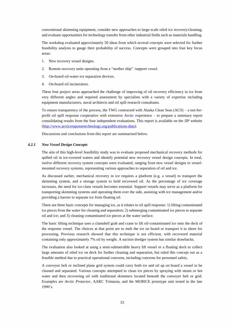
33
conventional skimming equipment, consider new approaches to large-scale oiled ice recovery/cleaning,
and evaluate opportunities for technology transfer from other industrial fields such as materials handling.
The workshop evaluated approximately 50 ideas from which several concepts were selected for further
feasibility analysis to gauge their probability of success. Concepts were grouped into four key focus
areas:
1. New recovery vessel designs.
2. Remote recovery units operating from a “mother ship” /support vessel.
3. On-board oil-water-ice separation devices.
4. On-board oil incinerators.
These four project areas approached the challenge of improving of oil recovery efficiency in ice from
very different angles and required assessment by specialists with a variety of expertise including
equipment manufacturers, naval architects and oil spill research consultants.
To ensure transparency of the process, the TWG contracted with Alaska Clean Seas (ACS) – a not-for-
profit oil spill response cooperative with extensive Arctic experience – to prepare a summary report
consolidating results from the four independent evaluations. This report is available on the JIP website
(http://www.arcticresponsetechnology.org/publications-data).
Discussions and conclusions from this report are summarised below.
4.2.1 New Vessel Design Concepts
The aim of this high-level feasibility study was to evaluate proposed mechanical recovery methods for
spilled oil in ice-covered waters and identify potential new recovery vessel design concepts. In total,
twelve different recovery system concepts were evaluated, ranging from new vessel designs to vessel-
mounted recovery systems, representing various approaches to separation of oil and ice.
As discussed earlier, mechanical recovery in ice requires a platform (e.g. a vessel) to transport the
skimming system, and a storage system to hold recovered oil. As the percentage of ice coverage
increases, the need for ice-class vessels becomes essential. Support vessels may serve as a platform for
transporting skimming systems and operating them over the side, assisting with ice management and/or
providing a barrier to separate ice from floating oil.
There are three basic concepts for managing ice, as it relates to oil spill response: 1) lifting contaminated
ice pieces from the water for cleaning and separation; 2) submerging contaminated ice pieces to separate
oil and ice; and 3) cleaning contaminated ice pieces at the water surface.
The basic lifting technique uses a clamshell grab and crane to lift oil-contaminated ice onto the deck of
the response vessel. The choices at that point are to melt the ice on board or transport it to shore for
processing. Previous research showed that this technique is not efficient, with recovered material
containing only approximately 7% oil by weight. A suction dredger system has similar drawbacks.
The evaluation also looked at using a semi-submersible heavy lift vessel or a floating dock to collect
large amounts of oiled ice on deck for further cleaning and separation, but ruled this concept out as a
feasible method due to practical operational concerns, including concerns for personnel safety.
A conveyor belt or inclined plane grid system could carry both ice and oil up on board a vessel to be
cleaned and separated. Various concepts attempted to clean ice pieces by spraying with steam or hot
water and then recovering oil with traditional skimmers located beneath the conveyer belt or grid.
Examples are Arctic Protector, AARC Trimaran, and the MORICE prototype unit tested in the late
1990’s.
34
In contrast to raising oiled ice pieces out of the water, a number of systems looked at submerging
contaminated ice pieces to release oil from ice by gravity separation. Oil separated from ice in this manner
rises through a grid system to a separate skimmer located on the water surface.
An example of these types of systems is the Lamor LOIS Oil Ice Separator used operationally in Finland.
These systems were designed to handle small ice pieces commonly encountered in the Baltic shipping
channels and cannot be readily scaled up to handle the weight and volume of ice pieces encountered in
the Arctic.
Cleaning contaminated ice pieces at the water surface includes the use of brush skimmers deployed from
a recovery vessel. For example, the recently developed Lamor Sternmax and the Finnish Environment
Institute (SYKE) stern brush system both use skimming systems with large brushes deployed off the
stern of a response vessel. The brushes rotate on top of the ice and between the ice pieces. The Sternmax
is also equipped with an oil separating grate that pushes broken ice pieces underwater away from the
brushes, the intent being that the oil floats free of the submerged ice.
In general, methods involving submerging ice pieces (limited by size) and separating oil and ice at the
water surface were found to have better feasibility for practical application than concepts involving lifting
ice out of the water. The limited swath width of all these systems limits their utility to small, contained
spills.
4.2.2 Remote Recovery Units
This feasibility evaluation aimed to identify various technologies related to remote recovery units (e.g.
units deployed separately and operating semi-independently from the “mother ship”), and determine their
feasibility for further research and development.
The key to successful mechanical recovery is maintaining the skimming unit in continual contact with
oil in the water. As discussed in 2.2.1, this requirement is difficult to satisfy in the presence of any
significant ice cover. Dependent upon location and environmental conditions, skimming systems used in
ice-covered waters are deployed from ice-capable vessels or barges. Examples include the Finnish oil
spill response vessels Hyljie and Louhi.
Ice-capable skimmers represent a number of different approaches; they typically incorporate a brush or
rope mop oleophilic skimmer and are deployed via an articulated hydraulic arm as shown below in Fig.
4.1. They can also be free floating or suspended by a crane in open water between the ice floes.
35
Photo: Finnish Environment Institute (SYKE)
Figure 4.1 Hyljie oil spill response vessel recovering oily bilge dumped into a winter shipping lane in the
Baltic Sea, April 2003.
Photo: VTT Technical Research Centre of Finland
Figure 4.2 Lamor brush bucket skimmer cleaning the surface of oiled ice in the Baltic Sea.
Examples of different brush skimming systems are the Desmi Helix, Desmi Polar Bear, and Lamor Oil
Recovery Bucket (Fig. 4.2 above). The Framo Polaris Skimmer is a self-propelled brush skimming
system (see Fig. 4.3 below). Some skimmers have a grid system to block larger pieces of ice while oil
flows through.

36
Photos: SINTEF
Figure 4.3 Framo prototype self-propelled Arctic skimmer being tested in the Norwegian Barents Sea.
With all of these systems, as the percentage of ice increases, the ice will further impede flow of oil to the
skimming system. This requires frequent recovery and repositioning of the skimmer into other fresh oil
pockets between floes. The presence of ice, especially brash and slush common between floes and in
leads will also impede the ability of self-propelled skimmers to maintain progress and access new areas.
The evaluation also considered a number of novel skimming support platforms such as articulated
amphibious vehicles, automatic deployment systems, cranes, auxiliary workboats, and containerised
systems such as balloons, aerostats, and other lighter-than-air vehicles.
Discussions included the possible use of oil under-ice recovery systems based on Remotely Operated
Vehicles (ROVs) and Autonomous Underwater Vehicles (AUVs) together with active containment
booms and pressurised air to move oil under ice for collection and pumping.
A concept based on the long reaching hydraulic articulated arms similar to those used in cement pumping
could conceivably carry an umbilical hose from the vessel to a floating skimmer. This could extend the
reach of a skimming system from the response vessel and assist in safely placing the skimmer in the
thickest oil patches, ultimately improving oil encounter and recovery rate of a skimming system.
In general the evaluation did not identify opportunities for significant improvements to existing skimmer
designs. The use of a long-reaching hydraulic system to deploy existing skimmer configurations based
on adapting existing technology was considered as potentially promising, but viewed more appropriate
for development by an oil spill equipment manufacturer than as subject of a JIP research project.
4.2.3 Onboard Oil - Water - Ice Separation
This high-level feasibility evaluation focused on “Oil-Water-Ice Separation” onboard a vessel during an
oil spill response operation. Availability of sufficient onboard storage for recovered fluids during a spill
event quickly becomes critical, especially in remote Arctic conditions without ready access for lightering
to shore. Optimising storage by separating recovered oil from ice and water is beneficial but challenging,
due to large volume of water and ice often recovered along with oil, and a wide variety of ice shapes and
sizes.
The evaluation acknowledged that separation could occur in three phases: 1) separation on the waterline
(at the water surface); 2) initial (coarse) on-board separation; and 3) secondary (more refined) on-board
separation.
There are several possible concepts for managing ice after oil and ice are brought aboard the vessel. One
concept is the Lamor Oil Water Ice (LOWI) Separator Basin. It consists of a clamshell bucket recovering

37
oil and ice from the water surface and placing it in a basin, which uses ice submergence, heating, and
pressure washing to separate oil from ice. It requires a 20-foot X 40-foot footprint onboard a vessel.
Another concept is the Lamor Shaker, which would utilise the clamshell bucket to recover oil and ice
from the water surface and place it into a shaker system.
The evaluation considered a variety of oil-water separation techniques and equipment types. Most of the
separation technologies available commercially on the market are designed to purify oily water with very
small concentrations of oil measured in parts-per-million (ppm). Some technologies are capable of
processing fluids with some solid particles, but none are designed to handle ice in different sizes and
forms (large, medium, small sized ice blocks and slush ice, etc.).
For separation purposes, melting ice pieces in large volumes is not feasible, due to the large amounts of
energy required. This finding echoes conclusions of other evaluations in this project, namely that due to
the complexity of the overall process, including the great variety in shapes and sizes of ice pieces
encountered and low oil concentrations, the separation of oil from ice and water is most efficiently
conducted at the water surface as currently achieved by existing skimmer systems. The downside of this
approach in the presence of ice is the low encounter rate that translates to correspondingly low recovery
rates.
4.2.4 On-Board Recovered Oil Incinerator
This study evaluated the possible use of recovered oil combustion systems to enhance mechanical
recovery of oil in offshore Arctic waters. The concept uses an incinerator on the storage vessel that burns
recovered oil, thereby freeing up storage space and decreasing the need to transport recovered fluids to
another storage location.
Studies in the 1970s and 1980s, looked at flare burner disposal systems for the disposal of recovered oil.
The intention was to address storage limitations during spill response in remote areas or ice-covered
waters.
With today’s technology, there are three concepts to consider: Pneumatic Flare, Rotary Cup Burner, and
Augmented Burner.
The Pneumatic Flare design concept operates in a manner similar to flare systems currently used in
offshore well testing. It uses pressurised flow through nozzles to atomise the oil, thus forming more
surface area to sustain a burn. A barge towed behind the oil skimmer systems would carry the system
and supporting components.
The Rotary Cup Burner concept consists of a modified helicopter-transportable burner system for
floating or at-sea operations. This system uses a high-speed rotating cup to produce a thin layer of fuel
at the lip of the cup, which is then atomised by air blown past the edge of the cup by an integral fan.
Rotary cup burners are lighter in weight and require less ancillary equipment than pneumatic atomising
flare burners.
The Augmented Burner concept is a chimney-style floating burner, which uses a pan to hold oil in a pool
burn, aided by a chimney and compressed air injection for inducing enhanced burning and more complete
combustion.
The evaluations concluded that the limited potential of onboard incineration to improve the overall
recovery effectiveness was more than offset by the need to add further complexity to an already complex
and resource-intensive operation.
4.2.5 Mechanical Recovery Achievements
The JIP evaluated all of the proposed concepts in the context of JIP research priorities using these criteria:
- Ability of a concept to significantly improve effectiveness of mechanical recovery in ice.

38
- Feasibility of turning a concept into field-capable operational unit.
- Feasibility of delivering project within JIP funding and timeline.
- Requirement for unique scientific and engineering input beyond what manufacturers can accomplish
through normal commercial product development.
The evaluation confirmed that substantial improvements in mechanical recovery efficiency could not be
readily achieved by new equipment designs. Instead, integrating field operations with advanced support
tools like real-time remote sensing could lead to greater improvements by enhancing the performance of
existing recovery systems, for example making sure they are positioned in the thickest oil films to
maximise encounter rates.
After evaluating the feasibility and limited probability of success of proposed mechanical recovery
projects against the likelihood of substantially increased capability though research in other areas such
as dispersants and in situ burning, the JIP decided not to allocate further funding to mechanical recovery.
Manufacturers are encouraged to continue improving their products in this area and to develop new
systems optimised for particular ice conditions, such as the MIZ.
4.3 In situ Burning
In situ burning (ISB) in ice and Arctic environments is a safe, environmentally acceptable and proven
technique supported by over four decades of research and operational experience (2.2.2).
New JIP research in this area focused on developing more effective ways of implementing burning at
remote sites offshore. The emphasis was on aerial delivery systems, taking advantage of recent research
into the use of herders to promote burning in open drift ice conditions and open water where slicks are
otherwise often too thin to burn in their natural state. With these overall goals in mind, the JIP technical
experts conceived a suite of projects using a combination of state of the art reviews, laboratory and basin
tests, field trials, and conceptual engineering design studies with these main objectives:
1. Review and disseminate the vast body of knowledge that exists on all aspects of ISB of oil slicks at
sea and particularly in the presence of ice and in cold climate conditions.
2. Develop and validate the concept of using herders in combination with burning as an operational
rapid response tool based on aerial delivery of both herders and igniters.
3. Conduct a conceptual engineering design study to evaluate the feasibility of developing a new aerial
ignition system capable of reaching remote offshore sites at higher speeds with greater capacity and
endurance than existing tools.
4.3.1 State of knowledge reviews
The JIP ISB research programme began by preparing a series of educational materials aimed at informing
industry, regulators and external stakeholders about the significant body of knowledge that currently
exists on all aspects of ISB: operational, environmental, and scientific.
Three comprehensive state of knowledge reports were developed: the first covers the roles, functionality,
benefits and limitations of ISB as a response option in the Arctic offshore environment including
planning and operational aspects and any potential impacts on human health and the environment; the
second reviews the findings of all relevant scientific studies and experiments as well as previous research
efforts on the use of ISB in Arctic environments both offshore and onshore; and the third summarises
and compares the regulatory requirements needed to obtain approval for use of ISB in Arctic nations.
(Buist et al., 2013a & 2013b; Potter et al., 2013)
Key findings were:
The technology exists to conduct controlled ISB of oil spilled in a wide variety of ice conditions.

39
ISB has a high potential for oil spill removal in specific Arctic conditions.
A considerable body of ISB scientific and engineering knowledge exists to ensure safe and effective
response in open water, broken pack ice and complete ice cover, based on over 40 years of research,
including a number of large-scale field experiments and successful implementation in large spills
such as the Deepwater Horizon incident response.
The use of approved procedures followed by trained personnel with necessary safeguards to protect
responders and any nearby residents can mitigate any risks associated with burning oil offshore. There are substantial differences in how regulators in the individual Arctic nation states approve
applications for ISB, either at the planning stages or during an actual emergency. By disseminating
the most current information on the state of knowledge in this field, it is hoped that the JIPs efforts
will lead to a more consistent and broader consensus on how to implement streamlined approvals to
facilitate the use of ISB in situations where Net Environmental Benefit Analysis (NEBA) can
demonstrate its environmental acceptability. Note: this latter proviso applies to all response tools.
4.3.2 Using Herders in Combination with ISB
ISB aided by herding agents is a promising tool for oil spill response in Arctic waters. In a report prepared
for the JIP, SL Ross and the Danish Centre for Energy and the Environment (2015) discuss the extensive
research and operational experience using herders in the laboratory, test basins and field environments.
Burn efficiencies in these experiments often exceeded 90%. However, all of these tests applied herding
agents and ignited the subsequent thicker slick from the surface; none used aerial systems.
A great advantage of the combined herder/ISB approach is that aerial platforms, manned or unmanned
in the future, can apply herder and then ignite the thickened slick. This could increase safety by
eliminating the need for having personnel on site to conduct marine operations on the sea surface, and
greatly reduce the response time required to mobilise and treat a spill in remote offshore areas. Only very
small quantities of herder are needed; for example, 150 µl/m2 is the recommended application dosage to
clear thin films of oil from large areas of water surface (Buist et al., 2017).
The JIP completed a series of related projects using consultants in Canada, U.S., Norway and Denmark
to advance the knowledge of herders and burning and develop improved aerial delivery systems to elevate
this new response strategy from research to operational status.
1. Herder Windows of Opportunity
2. Fate and Effects of Herders
3. Large-scale Basin Tests with Aerial Herder Delivery and Ignition Systems
4. Development of an Integrated Aerial Herder Delivery and Ignition System
5. Offshore Burn Trials in Norway with Herders in Open Water
6. Development of Long Range Aerial Ignition System
The sixth project was implemented to support burning oil trapped in ice at greater distances from shore
than possible with existing ignition systems. This concept focused on the burning of thicker oil films
without the use of herders but could theoretically be used to ignite herded slicks if necessary.
Individual project summaries follow.
4.3.3 ISB Project 1: Herder Windows of Opportunity
In 2014/2015, the JIP sponsored a research project aimed at defining the fate and environmental effects
of herders in Arctic waters and the windows-of-opportunity for herder use in cold open water and loose
drift-ice conditions. Small-scale laboratory experiments in in Ottawa Canada and meso-scale
experiments at the U.S. Army CRREL facility in New Hampshire U.S.A. took place in 2014/15 to assess

40
the performance of two commercially available herders (ThickSlick 6535 and Siltech OP 40) with four
different crude oils (Buist et al., 2016 &2017).
Key findings were that:
The initial herded thickness achieved is a function of both herder and crude type;
OP-40 was generally better than ThickSlick 6535;
As the crude oils evaporated, in general, the herders became more effective, except when the
evaporation caused the oil’s pour point to increase to more than 8° to 10°C above the ambient
temperature: at that point neither herder could contract the oil;
Herders could contract lightly emulsified oil (25% water content), but not moderately emulsified oil
(50% water);
Low concentrations of slush ice on the water did not detract from the performance of the herders;
but, the presence of high concentrations of slush ice prevents the herders from reaching the edge of
the slick (and prevents the oil itself from spreading); and,
Gentle, non-breaking wave action appears to assist with herding.
4.3.4 ISB Project 2: Fate and Effects of Herders
Laboratory-scale herding and burning experiments took place at the Danish Centre for Environment and
Energy, and the Danish Technical University (DTU) using the same two herders and two of the same
oils (Alaska North Slope and Grane) tested previously (See 4.3.3 above). The aim of was to improve the
knowledge base for evaluating any potential environmental risk of using herders in connection with in
situ burning as an operational Arctic response strategy.
The results showed that after burning, the herder was mainly found on the water surface, with only very
small concentrations, 0.2 to 22.8 µg/L, found in the water column. These extremely low concentrations
are several orders of magnitude lower than concentrations necessary to cause toxicity as measured in
laboratory testing (Buist et al., 2016a; Fritt-Rasmussen et al., 2017).
In a related study carried out as one of the conditions of obtaining a permit to discharge herders in
Norwegian waters as part of the NOFO 2016 Oil on Water Exercise (See 4.3.7), the acute toxicity of the
herders ThickSlick 6535 and Siltech OP-40 were tested with the phytoplankton (S. preudocoststum) and
the copepod (A. tonsa) as test organisms. These organisms represent different trophic levels in the marine
food chain.
In the phytoplankton test, the acute toxicities were of the same magnitude for both herders. In the copepod
test, the acute toxicity of the silicone-based herder Siltech OP-40 was similar for both organisms. Siltech
OP-40 showed moderately higher toxicity than Corexit 9500 dispersant, and was significantly more toxic
than ThickSlick 6535 in the copepod test. Thickslick 6535 had an order of magnitude lower toxicity than
Corexit 9500 dispersant in the same test (Singsaas et al., 2017).
To put these test results into perspective, the lowest EC50 values for herders are typically in the same
range as the toxicity of the non-diluted water-soluble fraction of a moderately weathered crude oil. When
comparing the potential environmental impact of herders and dispersants it is crucial to consider both the
toxicity and the relative volumes used. Based on extensive testing and experience in the field, the amount
of herder applied to an oil slick is expected to be one to two orders of magnitude less than the volume of
dispersant needed to effectively treat the same slick.
Additional fate and effects studies at DTU included measurements of herder toxicity and
bioaccumulation on Arctic copepods (Calanus hyperboreus), and biodegradability of herders in Arctic
conditions. Most importantly, results showed that the concentration of herders required to produce acute
toxicity was approximately three orders of magnitude higher than the actual concentrations measured in
the water column after herders were used to facilitate an in situ burn in the lab. These results indicate
that in an operational spill response, bioaccumulation and the rate of biodegradation may not be important
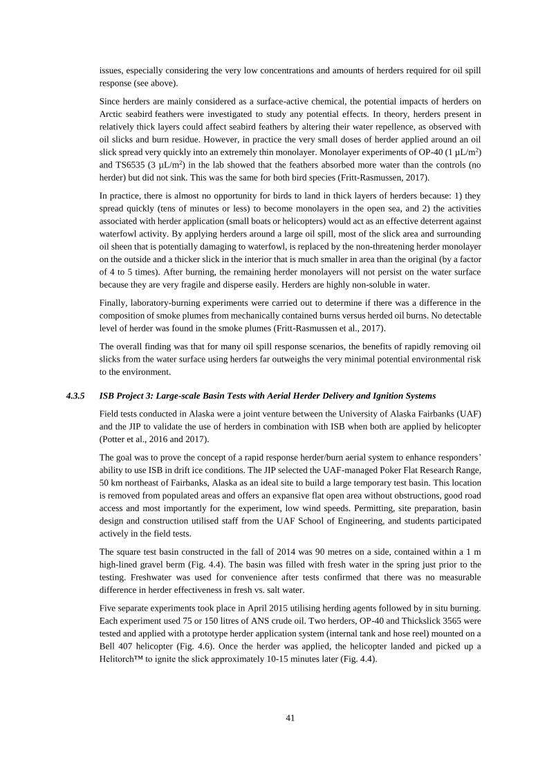
41
issues, especially considering the very low concentrations and amounts of herders required for oil spill
response (see above).
Since herders are mainly considered as a surface-active chemical, the potential impacts of herders on
Arctic seabird feathers were investigated to study any potential effects. In theory, herders present in
relatively thick layers could affect seabird feathers by altering their water repellence, as observed with
oil slicks and burn residue. However, in practice the very small doses of herder applied around an oil
slick spread very quickly into an extremely thin monolayer. Monolayer experiments of OP-40 (1 µL/m2)
and TS6535 (3 µL/m2) in the lab showed that the feathers absorbed more water than the controls (no
herder) but did not sink. This was the same for both bird species (Fritt-Rasmussen, 2017).
In practice, there is almost no opportunity for birds to land in thick layers of herders because: 1) they
spread quickly (tens of minutes or less) to become monolayers in the open sea, and 2) the activities
associated with herder application (small boats or helicopters) would act as an effective deterrent against
waterfowl activity. By applying herders around a large oil spill, most of the slick area and surrounding
oil sheen that is potentially damaging to waterfowl, is replaced by the non-threatening herder monolayer
on the outside and a thicker slick in the interior that is much smaller in area than the original (by a factor
of 4 to 5 times). After burning, the remaining herder monolayers will not persist on the water surface
because they are very fragile and disperse easily. Herders are highly non-soluble in water.
Finally, laboratory-burning experiments were carried out to determine if there was a difference in the
composition of smoke plumes from mechanically contained burns versus herded oil burns. No detectable
level of herder was found in the smoke plumes (Fritt-Rasmussen et al., 2017).
The overall finding was that for many oil spill response scenarios, the benefits of rapidly removing oil
slicks from the water surface using herders far outweighs the very minimal potential environmental risk
to the environment.
4.3.5 ISB Project 3: Large-scale Basin Tests with Aerial Herder Delivery and Ignition Systems
Field tests conducted in Alaska were a joint venture between the University of Alaska Fairbanks (UAF)
and the JIP to validate the use of herders in combination with ISB when both are applied by helicopter
(Potter et al., 2016 and 2017).
The goal was to prove the concept of a rapid response herder/burn aerial system to enhance responders’
ability to use ISB in drift ice conditions. The JIP selected the UAF-managed Poker Flat Research Range,
50 km northeast of Fairbanks, Alaska as an ideal site to build a large temporary test basin. This location
is removed from populated areas and offers an expansive flat open area without obstructions, good road
access and most importantly for the experiment, low wind speeds. Permitting, site preparation, basin
design and construction utilised staff from the UAF School of Engineering, and students participated
actively in the field tests.
The square test basin constructed in the fall of 2014 was 90 metres on a side, contained within a 1 m
high-lined gravel berm (Fig. 4.4). The basin was filled with fresh water in the spring just prior to the
testing. Freshwater was used for convenience after tests confirmed that there was no measurable
difference in herder effectiveness in fresh vs. salt water.
Five separate experiments took place in April 2015 utilising herding agents followed by in situ burning.
Each experiment used 75 or 150 litres of ANS crude oil. Two herders, OP-40 and Thickslick 3565 were
tested and applied with a prototype herder application system (internal tank and hose reel) mounted on a
Bell 407 helicopter (Fig. 4.6). Once the herder was applied, the helicopter landed and picked up a
Helitorch™ to ignite the slick approximately 10-15 minutes later (Fig. 4.4).

42
Figure 4.4 Large-scale basin tests of herders and burning in Alaska.
Notes to Figure: Aerial view of test basin (A); herder application device with herder nozzle magnified in
inset (B); application of gelled igniters via heli-torch (C); free-floating ISB viewed from ground level
observation point (D); close up of free floating ISB (E).
Two of the five tests yielded reliable, measurable outcomes, resulting in 70% - 85% removal of the oil
as it was drifting freely in the basin. In the other three test burns, the wind caused the slick to contact the
basin boundary before the herding and burning was completed, preventing an accurate measurement of
free-drifting burn efficiency – this issue was a known constraint of having to operate within the confines
of the basin and would not be a factor in an operational application offshore, where in most cases there
are no hard boundaries that would affect natural oil spreading and drift.
Additional testing both at Poker Flat and in Ottawa, Canada successfully used a small robotic helicopter
to apply herder and subsequently ignite a small test slick. This concept shows great promise for the future
but requires further engineering development and testing to become fully operational.
A key finding from the Poker Flat testing was that applying the herder with a separate system and then
igniting the herded slick with a Helitorch™ was not the most efficient. This led to a new project aimed
at developing an integrated system that combines the herder application tank, hose and nozzle with
igniters in a single airborne package (See 4.3.6 below).
The Poker Flat project was the first successful aerial application of herders for ISB in the Arctic or
elsewhere and furthers the development of better tools for oil spill response in Arctic waters and beyond.
A visitor’s day gave representatives from State and Federal U.S. government agencies the opportunity to
witness the herder/burn experiments. For many, this was their first experience with ISB and the overall
response was extremely positive.

43
4.3.6 ISB Project 4: Development of an Integrated Herder Delivery and Ignition System
Based on recommendations and experience from the experiments conducted at Poker Flat, Alaska (See
preceding 4.3.5) the JIP commissioned a project to review the state of the art for oil slick ignition and
develop an integrated herder delivery and ignition system that will enable both functions in one flight
without landing or hovering to pick up another load (Buist et al., 2016b; Lane et al., 2017).
The complete herder delivery system consists of a skid that contains the herder applicator, the herder
tank (75 litres), and the control system to operate the herder and an igniter system (triggered by Wi-Fi).
The accompanying DESMI Igniter launcher carried at the end of the hose used for herder delivery,
consists of a housing and ejection system (46 cm x 46 cm x 180 cm) for up to 15 cartridges. An explosive
cable cutter is built into the system so the pilot can drop the herder delivery hose and igniter system cable
at any time if there is a problem. With this safeguard, the FAA waives the need for any special type
certificate.
Initial system testing was done at CRREL in New Hampshire between 12 – 15 December 2016. A small
crane provided drop heights of 5 and 10 m above the oil on the water surface (Fig. 4.5). The initial test
was without oil, the next nine cartridge drops had oil in the tank, and in the last test the igniter cartridge
was released on the ice-covered portion of the tank to test its ability to impact a harder surface. Minor
design changes were made to the cartridges following these tests to improve their reliability but the
devices successfully ignited the oil slicks in their prototype form.
Figure 4.5 Test burn at the U.S. Army CRREL facility December 2016.
The full system was then installed in a Bell 407 helicopter and tested for airworthiness by JBI Helicopters
at Pembroke, New Hampshire U.S.A., with successful drops of dummy and live cartridges into target
areas painted on snow during January 2017 (Fig. 4.6). The tests identified the need for aerodynamic
refinements to the launcher shape to improve its flight characteristics but the system of remote control
(WiFi) from the cockpit and the cartridge ejection worked as designed.
The two sets of trials identified a number of modifications and improvements to the launcher, ignition
cartridges, and airworthiness that could quickly lead to production of a commercial version of the
integrated herder/burn system. Future enhancements being considered include: increasing the number of
cartridges, and adding a small heated herder tank and pump integral with the launcher enclosure
(eliminating the need for a long herder application hose extending from the cabin and using a simpler
wire rope).

44
For larger spills, the proven Helitorch™ offers the advantage of a much greater number of individual
ignition points compared to a cartridge system. When used on a separate winch cable as is available on
existing SAR helicopters, this option together with the internal herder tank/pump/reel tested in Alaska
(above) could potentially provide a “single flight” herder burn capability for much larger spills without
being limited by the number of igniter cartridges.
Figure 4.6 Integrated herder delivery and ignition system airborne trials.
Photos: Top left to bottom right: Ignition cartridges loaded in the launcher; launcher ready for hooking
up; herder delivery system installed; hooking up prior to flight tests
As a result of the JIP’s work in this area, industry now has access to several aerial systems that can ignite
naturally thick slicks (e.g. contained by ice) or thinner slicks (1mm or less) after the application of
herding agent. The basin and airworthiness testing in New Hampshire demonstrated that the prototype
cartridge-based igniter system could, with some minor design changes, be used now to treat small spills
in difficult to reach areas, such as trapped between ice floes offshore. The integrated aerial herder
delivery and ignition system provides a new tool to herd and burn small to medium sized spills in open
water or drift ice.
With the aerial application of both the herding agent and ignition source (igniter) now possible in a single
flight, the herder/burn combination becomes an extremely flexible, effective new rapid response tool that
can operate independently from the need to have direct vessel support at the spill site.
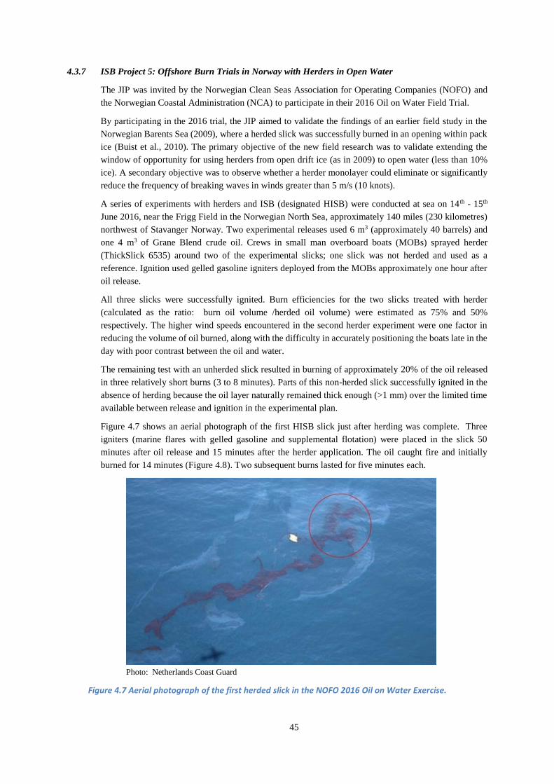
45
4.3.7 ISB Project 5: Offshore Burn Trials in Norway with Herders in Open Water
The JIP was invited by the Norwegian Clean Seas Association for Operating Companies (NOFO) and
the Norwegian Coastal Administration (NCA) to participate in their 2016 Oil on Water Field Trial.
By participating in the 2016 trial, the JIP aimed to validate the findings of an earlier field study in the
Norwegian Barents Sea (2009), where a herded slick was successfully burned in an opening within pack
ice (Buist et al., 2010). The primary objective of the new field research was to validate extending the
window of opportunity for using herders from open drift ice (as in 2009) to open water (less than 10%
ice). A secondary objective was to observe whether a herder monolayer could eliminate or significantly
reduce the frequency of breaking waves in winds greater than 5 m/s (10 knots).
A series of experiments with herders and ISB (designated HISB) were conducted at sea on 14 th - 15th
June 2016, near the Frigg Field in the Norwegian North Sea, approximately 140 miles (230 kilometres)
northwest of Stavanger Norway. Two experimental releases used 6 m3 (approximately 40 barrels) and
one 4 m3 of Grane Blend crude oil. Crews in small man overboard boats (MOBs) sprayed herder
(ThickSlick 6535) around two of the experimental slicks; one slick was not herded and used as a
reference. Ignition used gelled gasoline igniters deployed from the MOBs approximately one hour after
oil release.
All three slicks were successfully ignited. Burn efficiencies for the two slicks treated with herder
(calculated as the ratio: burn oil volume /herded oil volume) were estimated as 75% and 50%
respectively. The higher wind speeds encountered in the second herder experiment were one factor in
reducing the volume of oil burned, along with the difficulty in accurately positioning the boats late in the
day with poor contrast between the oil and water.
The remaining test with an unherded slick resulted in burning of approximately 20% of the oil released
in three relatively short burns (3 to 8 minutes). Parts of this non-herded slick successfully ignited in the
absence of herding because the oil layer naturally remained thick enough (>1 mm) over the limited time
available between release and ignition in the experimental plan.
Figure 4.7 shows an aerial photograph of the first HISB slick just after herding was complete. Three
igniters (marine flares with gelled gasoline and supplemental flotation) were placed in the slick 50
minutes after oil release and 15 minutes after the herder application. The oil caught fire and initially
burned for 14 minutes (Figure 4.8). Two subsequent burns lasted for five minutes each.
Photo: Netherlands Coast Guard
Figure 4.7 Aerial photograph of the first herded slick in the NOFO 2016 Oil on Water Exercise.

46
Note: The herded thick oil is easily visible and is surrounded by a ‘halo’ of thin oil sheen that had been
displaced by the herder. Most of the thick oil in the slick had been herded at this point, but about 15% to
20% of the thick oil remained unherded - marked with red circle. (Photo: Netherlands Coast Guard)
Photo: IOGP
Figure 4.8 JIP observer viewing the first Intense burn on the first herded slick.
The percentage of the total available oil volume that was herded was less than 100% in both tests
primarily because of the difficulty in clearly seeing the slick boundary from the small vessels used to
apply the herder and igniters; this became more challenging at low sun angles with overcast later in the
day. An important lesson from these tests was the need to have dedicated aerial observation platforms
(either manned or robotic helicopters) providing real time downlinked imagery directly to on-water
operators. In the NOFO trials, robotic helicopters provided valuable archival video footage but they were
not designed to deliver real-time operations support to the boat crews. Malfunction of the Aerostat
(Ocean Eye) adversely affected monitoring of surface oil and for guiding during herder and ignition
operations. The ideal solution is a wholly aerially based herder/ignition system operating independently
from surface support (See ISB Project 4 discussed above).
On day two of the field trial, a test with herder only was conducted. Wind conditions picked up to 15
knots (7.5 m/s) causing numerous white caps on the sea surface. The goal of this test was to determine if
the herder itself would reduce the severity of breaking waves. Prior research indicated that herders could
dissipate wind-driven waves at sea (Alpers & Huhnerfuss, 1989). Validating this hypothesis could
improve the operational window-of-opportunity estimates for herders based on wave-basin tests. Four
litres of herder placed on the ocean surface spread to produce a distinct 100 m x 500 m smooth surface
indicating the presence of a surface film. This condition persisted for over 1 hour. Review of infrared
video of the herded patch compared to an equivalent size adjacent patch of water indicated that white
caps in the herded patch were up to 50% less in number and somewhat less energetic. These results
provide some evidence that herders can potentially be used in wind speeds up to 7 m/s (14 kt),
approximately double the wind threshold defined as a no-go condition based on previous research.
The experiments provide additional verification that herders could contract oil slicks for effective
ignition in relatively calm open waters (2 to 5 m/s wind speeds), expanding the use of this tool from
strictly ice environments to Arctic summer months or open water in more temperate climates.

47
Further field trials of the herder/burn concept are needed to provide better field estimates of likely burn
efficiencies achievable with this countermeasure and confirmation of the absolute weather limitations
for its effective use. Ideally, the newly developed integrated aerial herder/burn system (described above)
would form part of any future tests at sea. This system was not available in time for the NOFO 2016
trials. Full details on the NOFO project are provided in Singsaas et al. (2017) and Cooper et al. (2017.
4.3.8 ISB Project 6: Development of a Long-range Aerial ignition System
There is a need for an ignition system that can deliver larger payloads of gelled fuel hundreds of
kilometres from a support airport or offshore facility, to support in-situ burn (SB) operations in ice. The
primary scenario requiring such an operation involves a track of oiled ice that could remain in the
aftermath of a major incident involving loss of well control at the end of the drilling season. In that case,
oil trapped beneath the new or young ice could drift through the winter and naturally migrate to the ice
surface in the spring when the ice warms. Previous studies have shown that this process can lead to a
high percentage of the oil initially spilled becoming available for ignition a month or more before final
ice break-up (Norcor, 1975; Dickins and Buist, 1981; Brandvik et al., 2006).
The effectiveness of ISB operations at remote Arctic locations offshore is constrained by logistics and
safety considerations. Handheld igniters require a stable ice cover for work crews to access the oil or
small boats deployed from support vessels. The Helitorch™ carried as a slung load greatly slows the
helicopter and results in a limited radius of action. In addition, the standard Helitorch™ tank capacity is
not sufficient to treat a large enough area of oiled ice without excessive downtime for reloading and
refuelling.
The objective of this JIP research project was to develop a fixed and rotary wing conceptual solution for
a longer range, higher capacity aerial ignition system than currently available. The project proceeded
through five stages leading to a final conceptual design capable of being certified by either the Federal
Aviation Administration (FAA) or the European Aviation Safety Agency (EASA).
1: Identify suitable aircraft.
2: Develop conceptual design for a distribution and ignition system.
3: Identify FAA approval requirements.
4: Identify location for on-shore testing
5: Identify priorities for integrated systems testing.
The contractor, Waypoint (an aeronautical engineering specialist), analysed over 23 candidate aircraft
for the project. Earlier ground-based tests in Alaska demonstrated the feasibility of sustaining gelled fuel
ignition at air speeds up to 100 mph (Preli et al., 2011). Two aircraft were chosen as warranting further
consideration: the Sikorsky S92 and Casa 212 (Fig. 4.9). Both aircraft are capable of carrying out a long
range ISB mission with 300 gallons (1135 litres) of gelled fuel, and operating safely in the required low
speed range close to the ice surface. Helicopters offer the advantage of much lower speed down to a
hover if necessary; to survey the ice and spot oiled pools at very low altitudes.

48
Sikorsky S-92
Casa 212
Photos: Wikipedia Commons
Figure 4.9 Aircraft selected as primary candidates for the long-range aerial ignition system.
The overall concept for the ignition system is based on extending the proven Helitorch™ technology and
adapting it to higher speeds. The main difference here is that the gelled fuel is ejected behind a rapidly
moving airplane or helicopter. The system would maximise the use a number of “off the shelf”
aeronautical (e.g. the hose and drogue would draw on proven in flight refuelling hardware) and non-
aeronautical parts to save on design and manufacturing costs.
Figure 4.10 Plan and profile view of the palletized system.

49
Figure 4.11 Profile view of the palletized ignition system mounted in a Sikorsky S-92.
The engineering study successfully produced a conceptual design of a palletized airborne ignition system
capable of rapid installation in a Casa 212 airplane or S-92 helicopter. Both aircraft have the payload
capacity to handle a 300-gallon (1135 litre) gel fuel tank and a rear ramp to accommodate a trailing hose
and nozzle to eject and ignite the fuel globules and treat an oiled track approximately 50 km in length
and 10 to 15 m in width. The ability to achieve Federal Aviation Administration (FAA) and or European
Aviation Safety Agency (EASA) approval was a primary consideration throughout the design process
(Waypoint and SL Ross, 2017).
4.3.9 ISB Achievements
The JIP’s ISB research and development programme:
Reviewed and disseminated a vast body of knowledge on all aspects of in situ burning of oil slicks
at sea and particularly in the presence of ice and in cold climate conditions.
Developed and validated the concept of using herders in combination with burning as an operational
rapid response tool with aerial delivery and ignition.
Confirmed that the application of small volumes of herders poses no significant environmental risk.
Provided additional verification that herders could contract slicks for effective ignition in open
water, adding to the successful experience in a previous JIP with herders and burning in the presence
of ice.
Developed and tested a prototype airborne system that integrates the ability to apply herder from a
helicopter and then ignite the treated slick in a single flight.
Conducted an engineering study that produced a conceptual design of an easily installed, skid-
mounted airborne ignition system capable of rapid installation in a suitable fixed wing airplane or
helicopter. This development could enable access to remote offshore sites at higher speeds with
much greater capacity and endurance than existing aerial ignition tools.
4.4 Dispersants
At the outset of the programme, the JIP commissioned a series of three state of knowledge reports on the
use of dispersants (4.4.1/2/3). Following these assessments, the JIP carried out a series of basin tests,

50
field data collection and modelling studies, looking at different aspects to the use of dispersants as a
response tool. The research work was divided into four main projects with these objectives:
1. Fate of Dispersed Oil Under Ice: A modelling study to understand how dispersed oil plumes are
likely to behave under ice from the perspective of their resurfacing potential with different levels of
turbulent mixing energy (4.4.4).
2. Evaluating the Boundaries for Dispersant Use in Ice: Basin testing to evaluate the effects of oil type,
dispersant type, weathering and water salinity on dispersant effectiveness (4.4.5) and including a
related separate study: Evaluating the dispersibility of oil frozen into the ice throughout the winter
(4.4.5.1)
3. Modelling to Determine Fate of Oil After Subsea Dispersant Injection (SSDI) (4.4.6): A modelling
study to predict oil surfacing and surface-oil persistence as a function of wind and water depth.
4. Evaluating potential population changes to fish populations as a result of dispersant application
(4.4.7).
4.4.1 State of Knowledge: Fate of Dispersed Oil Under Ice
This report summarised the state of knowledge regarding the fate of dispersed oil under ice. Key points
are:
The fate of a cloud of oil droplets under ice depends mainly on the droplet size distribution, the
vertical turbulence profile, and the horizontal transport field. The longer the droplets are retained in
the water column, the more the droplet cloud will become diluted due to horizontal mixing, and the
more the oil will biodegrade. Oil droplets that resurface under the ice will also not tend to reform
into larger slicks or pools.
This literature review supported the view that while sufficient knowledge exists to develop an under-
ice turbulence closure model, existing observations and measurements of under-ice turbulence are
probably not adequate to provide the necessary calibration and verification data. This conclusion led
to the research program described below in 4.4.4.
Reference: JIP Technical Report by Beegle-Krause et al., (2013)
4.4.2 State of Knowledge: Effectiveness of Dispersants in Ice
This report summarised the state of knowledge regarding the effectiveness of dispersants in ice from
previous research. Key points are:
The presence of ice pieces on the water surface in wave tanks increases dispersant effectiveness,
compared to the same test oil/dispersant DOR/wave energy combination without ice.
As with dispersant use on oils in open water, increased mixing energy can partly overcome the
resistance of weathered (more viscous oil) to dispersion.
Studies in flume basins and at sea have demonstrated that the weathering processes are slowed down
when ice is present, enabling a longer “time window" where effective dispersant application is
possible.
Where the natural surface mixing energy with ice is insufficient, the addition of mixing energy (for
example through azimuthal stern drive units on icebreaking support vessels) can create sustained
dispersion.
Reference: JIP Technical Report by Lewis (2013)

51
4.4.3 Status of Regulations and Outreach Opportunities
This report describes:
o The present status of regulations related to the use and or limitations of dispersants in 21 Arctic
countries or those countries that have ice-affected waters;
o The potential obstacles to achieving permission to conduct dispersant operations in jurisdictions
where their use is not presently allowed or restricted; and
o Strategies to address identified obstacles and potential opportunities to communicate the
benefits and merits of dispersant application as a response countermeasure.
The report suggests that obtaining blanket nationwide pre-approval for dispersants from all ice-
affected countries is probably unlikely. However a feasible goal is helping countries with oil and gas
activities in ice-affected waters appreciate the potential benefit of an expedited process to approve
the use of dispersants, including at least a limited policy authorizing dispersants in specific areas,
and potentially pre-approval for specific projects.
Many of the nation states addressed in this document require a NEBA to as a precondition to any
consideration of dispersant use. Receiving approval to use dispersants within the available window
of opportunity may require two levels of NEBA at: (1) a strategic level and (2) a tactical level. A
strategic NEBA would consider the overall potential value of dispersants as a response tool and
would explore possible spill situations in a specific county. If a country develops a policy to allow
the use of dispersants, tactical NEBAs would become a tool for evaluating whether or not dispersants
are useful in a specific planning scenario or actual incident. NEBAs should be expanded to include
economic, social and public health considerations.
Reference: JIP Technical Report by SEA (2013)
4.4.4 Fate of Dispersed Oil under Ice:
The goal of this project was to develop a numerical model capable of predicting the resurfacing potential
of a dispersed oil plume that develops under ice after applying dispersant from the surface, with and
without adding mechanical mixing energy. Oil spill plume models exist for open water but not for
situations with significant ice cover. In order to prepare a model to predict the fate of an oil plume under
ice, information describing the turbulence just below the ice-water interface was needed. Consequently,
much of the project effort focused on collecting the turbulence data required as input to the model.
Two dispersed oil scenarios were evaluated: (1) oil treated with dispersants and then dispersed with
natural wave action; and (2) oil treated with dispersants and then dispersed with the propeller wash of an
icebreaker. These two scenarios had one fundamental difference. Natural dispersion through wave-action
would result in a plume penetrating only one to two metres below the ice. In contrast, the propeller-wash
dispersion would result in a plume that potentially penetrates 15 – 20 m below the ice.
The study programme combined laboratory studies with oil droplets and on-ice field experiments on
Svalbard with dye to set the stage for simulating an oil spill – without releasing any oil in the
environment.
Mesoscale laboratory studies in a 35-metre long flume at Plymouth University in the UK allowed the
release of oil droplets of known size (63µm, 88µm, 125µm, 299µm) in water flowing under synthetic ice
under controlled conditions: three different current profiles with peak velocities of ~2.5cm/s, ~5.5 cm/s,
and ~12.5 cm/s, and three different levels of under-ice hydraulic roughness (Fig. 4.13). By allowing over
100 oil release experiments, the flume tests allowed the collection of additional turbulence data over a
much broader range of current and ice conditions than were possible in the field (Beegle-Krause et al.,
2017).

52
Figure 4.12 Researchers measuring the spreading of a dispersed oil plume in a flume.
Instruments placed through the ice in two field experiments during the spring of 2015 and 2016 collected
data on under-ice turbulence. The goal was to collect data under very low-energy conditions expected
under stable, smooth fast ice (attached to shore) in a fjord near Svea, Svalbard (Fig. 4.13). In the second
field experiment in 2016, the team released and followed dye under the ice in order to measure dilution,
as a check on the model. Data representing this low end of the turbulence spectrum was not available at
the outset of the JIP.
Figure 4.13 Field-testing in van Mijenfjorden in Svalbard, Norway in April 2016
Turbulence data collected in the field programmes and in the flume were used in a plume model to
generate 525 tables, with estimates of the percentage of oil droplets with various diameters and densities
that could potentially resurface if they effectively dispersed under ice with three different levels of
ambient turbulence. The modelling based on a model developed by McPhee (2008), assumed that a fully
developed dispersed oil plume had already formed. The model was not used to predict droplet sizes that
SINTEF Materials and Chemistry
Environmental Monitoring and Modelling 2016-11-30
F27960- Restricted
Report
Fate of dispersed oil under ice, Phase 2
Under-ice observations of low-energy hydrodynamics and under-ice dye study in van Mijenfjorden, Svalbard, Norway, April 2016
Author(s) CJ Beegle-Krause, Ragnhild L. Daae, Alex Nimmo-Smith, Miles McPhee, Emlyn Davies, Liv-Guri Faksness

53
would form during initial dispersion. Rather, the model for each scenario ran with a range of droplet
sizes from 30 µ to 110 µ microns. As an operational reference point, Nedwed et al. (2006) reported on
basin testing where the average median particle diameter after simulating the introduction of mechanical
mixing energy from an icebreaker’s stern drive units, ranged from 16.6 μm to 45.0 μm.
Using an example for a medium crude oil (0.85 s.g.) dispersed down to a depth of 10 m with the addition
of mechanical mixing energy, the available model data shows that the majority of droplets 30 µ or smaller
would remain dispersed for up to 24 hours (Beegle-Krause, et al., 2017). Further work is required to
ensure that the existing model is capturing all of the important aspects of the physics controlling droplet
rise in different water turbulence regimes.
4.4.5 Evaluation of the Boundaries for Dispersant Use in Ice:
The purpose of this project was to study the effects of different variables governing the use of dispersants
in ice. Approximately 70 tests took place in identical recirculating flumes in laboratories in Canada and
Norway (Fig. 4.14). Variable parameters included oil types, dispersant type, mixing energy, ice coverage,
and water salinity. Oil weathering in the flumes spanned 6 or 18 hours under simulated winds, waves,
and cold temperatures to represent weathering that might occur at sea prior to dispersant application. The
dispersed oil was exposed to various mixing energies, starting with low energy, followed by high energy,
and finally by applying propeller wash. The dispersant efficiency of three commercial oil spill dispersants
was evaluated for four crude oils. Other test parameters were ice coverage (50% and 80%) and water
salinities (35, 15, and 5 ppt).
Figure 4.14 Plan view SL Ross and SINTEF recirculating flumes.
Results from the flume-based experiments established boundaries for dispersant effectiveness as a
function of the different test variables. As expected, shorter weathering times resulted in an increase in
dispersant efficiency. The dispersant effectiveness varied with both oil type and dispersant type applied,
and the effectiveness increased when higher mixing energy conditions were used. Varying the ice cover
did not influence the results significantly, but water salinity did, with the poorest dispersant efficiencies
found at 5 ppt salinity.
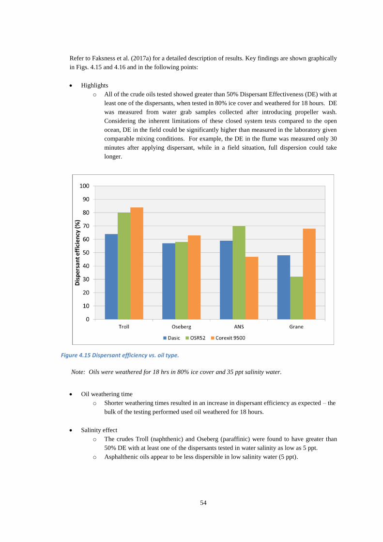
54
Refer to Faksness et al. (2017a) for a detailed description of results. Key findings are shown graphically
in Figs. 4.15 and 4.16 and in the following points:
Highlights
o All of the crude oils tested showed greater than 50% Dispersant Effectiveness (DE) with at
least one of the dispersants, when tested in 80% ice cover and weathered for 18 hours. DE
was measured from water grab samples collected after introducing propeller wash.
Considering the inherent limitations of these closed system tests compared to the open
ocean, DE in the field could be significantly higher than measured in the laboratory given
comparable mixing conditions. For example, the DE in the flume was measured only 30
minutes after applying dispersant, while in a field situation, full dispersion could take
longer.
Figure 4.15 Dispersant efficiency vs. oil type.
Note: Oils were weathered for 18 hrs in 80% ice cover and 35 ppt salinity water.
Oil weathering time
o Shorter weathering times resulted in an increase in dispersant efficiency as expected – the
bulk of the testing performed used oil weathered for 18 hours.
Salinity effect
o The crudes Troll (naphthenic) and Oseberg (paraffinic) were found to have greater than
50% DE with at least one of the dispersants tested in water salinity as low as 5 ppt.
o Asphalthenic oils appear to be less dispersible in low salinity water (5 ppt).

55
Figure 4.16 Dispersant efficiency vs. water salinity.
Note: Oils were weathered for 18 hrs in 80% ice cover. No bars indicate that no testing was performed.
4.4.5.1 Dispersibility of Oil Frozen Into Ice
An additional test series was added to take advantage of ice cores with oil alone and oil premixed with
dispersant frozen into the upper layer of the ice. The cores were obtained during the environmental effects
field experiments with mesocosms on Svalbard (See 4.7.2). Following collection one, two, and three
months into the ice growth cycle, the cores stored at very cold temperatures were subsequently melted
in a laboratory at Cedre in France to simulate spring melt and the release of oil into open water. The
samples were then treated with dispersant and subjected to a standard qualitative field dispersant
effectiveness test. The results clearly showed that the oil remained dispersible even after three months
of being frozen into the ice regardless of whether it was premixed with dispersant before being
incorporated within the ice. In fact, oil frozen in the ice cores dispersed as well or better than fresh oil.
Figure 4.17 shows images of the tests comparing dispersion of the oil that was not weathered in ice with
the same oil type that was weathered for three months in ice.

56
T0 T+1 min T+5 min T+15 min
Fresh Oil Treated
with Dispersant
(no weathering in
ice)
T0 T+1 min T+5 min T+15 min
Oil Frozen into
Ice for 3 months
and then Treated
with Dispersant
Figure 4.17 Comparison of the dispersion of fresh oil treated with dispersant (upper) to oil frozen into
ice for 3 months and then treated with dispersant (bottom).
4.4.6 Modelling to Determine Fate of Oil from Releases with Subsea Dispersant Injection (SSDI)
The objective of this study was to evaluate how injecting dispersants during a subsurface release changes
the fate of the oil. The study used SINTEF’s OSCAR model with an updated algorithm for droplet size
predictions and improved prediction of oil temperature and resulting viscosity during droplet formation.
In total, model runs simulated 30 different subsea releases of oil and gas mixtures with varying release
depths (50, 150, 300, 700 and 1,000 m) and three different wind speeds (0, 5 and 10 m/s - constant and
in one direction) and with/without subsea injection of dispersants (SSDI).

57
The OSCAR simulations indicated that SSDI could significantly alter the rise velocity of oil droplets
from a subsea release. Subsea dispersant injection keeps the oil droplets in the water column for longer
periods thereby allowing greater natural biodegradation and dissolution of the oil. The result is that less
oil reaches the surface and the oil that does surface produces thinner slicks compared to untreated
releases. The thinner slicks do not persist on the surface because they have a lower tendency to emulsify
and rapidly re-disperse with wave action. This shorter residence time reduces the potential for
environmental impacts on surface dwelling marine organisms or seabirds, while lowering the risk of
respiratory impacts for responders working close to the oil release site.
Figures 4.18 and 4.19 simulate the oil mass balance with and without SSDI at 700 m depth with two
different wind speeds out to 10 days (8 days after the end of the release). With a 5 m/s wind speed, the
scenarios with SSDI show significantly less oil on the surface. For example, at the end of the two-day
release period the scenario comparison shows that the use of SSDI could potentially reduce the amount
of oil on the surface from 60% to 20% of the original discharge volume. An increase in wind speed to 10
m/s further reduces the amount of oil left on the surface, to less than a few percent of the original spill
volume when SSDI is used in this water depth with stronger winds (Fig. 4.19). Refer to full project results
in Faksness et al. (2017b).
Figure 4.18 Model predictions of oil mass balance with and without SSDI: 700 m water depth, 5 m/s
wind
Figure 4.19 Model predictions of oil mass balance with and without SSDI: 700 m water depth, 10 m/s
wind

58
4.4.7 Estimated Impacts of Hypothetical Oil Spills in the Alaska Beaufort Sea on Arctic Cod
This project describes a scientific approach to evaluating potential population changes to Arctic cod
Boreogadus saida from hypothetical oil spills in the central shelf area of the Alaskan Beaufort Sea. This
approach is used to estimate potential population changes for two response options: treating the spill with
dispersant or leaving the spill untreated. Effective dispersant treatment rapidly transports oil from the sea
surface into the water column. Oil left on the surface can persist and impact sea birds and other species
for an extended time. Oil transferred into the water column increases the exposure of water column
organisms but this exposure is transient as oil rapidly dilutes and biodegrades to mitigate the
environmental threat. The purpose of this project was to demonstrate that using dispersants could lead to
a substantial net environmental benefit by removing oil from the water surface while affecting an
insignificant proportion of the fish population.
The approach uses a fecundity-hindcast model that incorporates Arctic cod acute toxicity data, field
studies of Arctic cod larval distribution and abundance, natural mortality estimates for Arctic cod eggs
and larvae, and an oil spill fate model. Planktonic life stages of Arctic cod were considered the most
susceptible to oil spill exposure. Volumes of water that exceeded measured acute toxicity thresholds
(known in biological terms as the 96-hour LC50) for Arctic cod larvae were estimated using the oil spill
fate model. These volumes combined with field measurements of cod larval distribution and abundance
were then used to estimate exposure of Arctic cod planktonic life stages to oil in the water column. The
researchers took the very conservative approach that any planktonic life stage exposed for even one hour
(the time step used for the oil spill model) was lost from the system even though the acute toxicity
thresholds used to determine water volumes with the model were based on 96-hour exposures. Several
other conservative assumptions were that the spill was assumed to overlap the highest density of fish
observed in the study area and that the entire volume of oil was dispersed at once when in practice this
would occur in stages through a response over days to weeks. Using this methodology conservatively
overestimated potential actual losses to the system for the hypothetical spills evaluated.
The paper evaluates multiple scales of spill events (1,000 tons, 10,000 tons, 100,000 tons) for both
physically (the fraction of the oil that would naturally disperse without using dispersants) and chemically
dispersed oil. In the worst case, a 100,000-ton spill of crude oil treated with dispersants resulted in 266
million m3 of water that exceeded the acute toxicity threshold, compared to a volume of 71 million m3
for a 100,000-ton spill not treated with dispersants. The difference is that in the first case, surface slicks
are dispersed and in the second case, the oil remains on the surface to potentially impact marine mammals
and seabirds.
A 100,000-ton spill treated with dispersants resulted in exposure of fish larvae representing the
reproductive output of less than 1/10 of one percent (0.07%) of the Arctic cod population in the Alaska
Beaufort Sea region. The impact calculations use the lowest estimate of total cod populations while
assuming that the highest density of fish population occurs within the spill area. Some population
estimates have numbers of fish ten times greater, which would make the population impact of dispersed
oil ten times less (0.007% population affected). Regardless of the assumptions involved in the final
estimate, the results clearly show that no significant impacts on the regional population would result from
applying dispersants to the largest spill scenario modelled (Gallaway et al., 2017).
4.4.8 Dispersant Research Achievements
The JIP’s dispersant research program significantly increased our understanding of dispersant use in the
presence of ice in a number of areas highlighted in the following points:
Three state of knowledge reviews summarising past research into dispersant fate and
effectiveness and the status and scope of panarctic regulations (or lack thereof) governing
the use of dispersants.

59
An existing model was used to predict the resurfacing potential of a dispersed oil plume
under ice with and without the addition of mechanical mixing energy.
An existing model demonstrated the potential environmental benefits of SSDI in
significantly reducing the percentage of oil surfacing from a subsea release and the
subsequent persistence of surfaced slicks in different water depths and wind speeds.
New data sets of expected dispersant effectiveness in ice as a function of a wide range of
physical variables will help regulators, planners and responders understand how dispersants
are likely to perform in different scenarios.
Modelling results showing that the use of dispersants in response to a large incident would
likely result in insignificant impacts to Arctic Cod populations as an example.
Proof that oil frozen into the ice surface through the winter remains dispersible when
released from the ice the following summer regardless of whether the oil already contained
dispersant at the outset.
4.5 Remote Sensing
In order to mount an effective response that uses all possible response options: containment booms,
mechanical recovery, dispersants, and in situ burning (ISB), it is critical to know where the spilled oil is
at any given time, and the boundaries of the contaminated area. This is achieved through a combination
of surveillance (relying heavily on remote sensing), tracking beacons and trajectory modelling (See 4.6).
The presence of sea ice increases the complexity of detecting the oil from satellites, aircraft, vessels or
subsea platforms. Ideally, any Arctic surveillance program will also provide some indication of the
relative distribution of oil thickness and therefore the location of the thickest patches to guide responders
in deploying response tools where they are most effective.
The JIP conducted a series of projects to assess and improve remote sensing and monitoring capabilities
in darkness and low visibility, for oil on the ice surface, on the water between floes, and trapped
underneath or within the ice.
1) State of Knowledge Reviews
2) Evaluation of Sensor Capabilities
3) Evaluation of Infrared Sensors to Detect Oil on Ice
4) Evaluation of an Airborne Radar to Detect Oil in Ice
5) Remote Sensing Guide
The following sections summarise the results of these five projects.
4.5.1 Reviews of Existing Remote Sensing Technologies
The JIP prepared two state of knowledge reports at the outset, covering:
Surface remote sensing using platforms such as satellites, aircraft, UAS, vessels and on-ice
systems (Puestow et al., 2013).
Subsea remote sensing using platforms such as Remotely Operated Vehicles (ROVs) and AUVs
(Wilkinson et al., 2013).
Each of these reports summarises the existing platforms and technologies available to detect oil in, under
and around ice from space borne, airborne, surface and subsea remote sensing platforms and sensors. A
common finding was that responders already have access to a wide range of potentially capable systems
used from a variety of platforms such as satellites, helicopters, fixed-wing aircraft, drones, vessels and
drilling platforms. While most of these sensors were originally developed, tested and used operationally
to support oil spill responses in open water it was found that many of the same systems could potentially

60
provide effective oil detection in a broad range of water and ice combinations as well (Section 2.2.4
provides a summary of the state of knowledge in remote sensing in ice at the outset of the JIP).
A key recommendation mirrored in both the surface and subsea remote sensing technology reviews was
the need to test and validate existing sensors (above and below ice) in varying oil and ice scenarios. The
JIP developed this need into Phase 2, described below in 4.5.2.
4.5.2 Evaluation of Sensor Capabilities
Based on the recommendations from the Phase 1 reviews, the JIP initiated an ambitious test programme
to evaluate and qualify the most promising sensors and platforms with crude oil released under a solid
ice sheet in a temperature controlled environment. Research experiments at the U.S. Army Corps of
Engineers-Cold Regions Research and Engineering Laboratory (CRREL), Hanover, New Hampshire,
evaluated the performance of various surface and subsea remote sensing technologies (Pegau et al., 2016
and 2017; Lamie and Zabilansky, 2017). This test program represented the first deployment of an array
of above surface and subsea sensors under controlled conditions with simultaneous multi-sensor data
collected through a series of oil releases spanning an entire ice growth cycle from initial freeze-up to the
final melt.
The CRREL test basin measures 37 m long, 9 m wide, and 2.4 m deep. Six containment hoops were
placed along the length of the tank to make up the primary experimental area. Six smaller hoops received
the same treatment as the primary hoops to allow for coring to examine ice properties. Another four
hoops were provided for additional experiments (Figure 4.20).
Figure 4.20 Oil containment hoop placement in the CRREL ice test basin.
Sensor testing began in November 2014 and spanned a two-month ice growth phase ending with an 80
cm thick sheet of level salt-water ice and followed with a one-month decay/melt period. At predetermined
stages, Alaska North Slope (ANS) crude oil at 0°C was injected into each hoop from below (Fig. 4.21).
A weekly transect was made both above and below the ice to allow sensors to collect data along the
length of the ice sheet with oil layers at different depths within the ice.

61
Figure 4.21 Cross section of CRREL test basin showing above and below ice sensor carriages and oil
layers.
Above-ice sensors were mounted on a long boom fastened to a moving carriage above the ice, and
included: a Frequency Modulated Continuous Wave (FMCW) radar, ground penetrating radars (GPR)
operating at two frequencies, visible and infrared cameras, and laser fluorescence polarization (FP)
sensor. GPR and optical measurements were also collected through spot measurements at the ice surface.
Below-ice sensors were mounted on a trolley running on rails mounted on the tank bottom at a depth of
two metres, and included: spectral radiance and irradiance sensors, FP sensors, optical cameras,
broadband acoustics (3 frequency bands), narrowband acoustics (4 frequencies), and multibeam
acoustics (3 sensors).
A team of modellers used the data collected within the discrete range of parameters possible in the test
basin (ice thickness, oil pool depth, ice salinity) to predict sensor performance over a wider range of ice
conditions. This effort involved determining the expected optical, acoustical, and radar properties of a
typical sea ice sheet at different times of the year. Specialised tests in the basin used three-dimensional
computerised tomography (CT) scans to produce detailed fine scale (mm) information on brine and air
inclusions in the ice, along with the crystal structure at the ice water interface known as the skeletal layer
that strongly influences the radar and acoustic reflections from the ice/oil/water interface (Courville et
al. 2017). This data provided valuable inputs for the modelling team and helped in understanding why
different sensors performed as they did in a particular situation.
The matrix in Fig. 4.22 summarises the findings of the ice basin tests and the modelling predictions.

62
Location Airborne On ice Below ice
Sensor GP
R
FMC
W
Optical FP IR GPR Optical FP Acoustic
Fall-Winter-
Spring
Exposed oil on
ice
N/A N/A
Snow covered oil
on ice
Fresh oil under
ice or with up to
6 cm new
growth)
Encapsulated oil
(more than 6 cm
new growth)
Summer
Exposed oil on
ice
N/A N/A N/A N/A
Figure 4.22 Expected field performance for sensors tested during the 2015 ice basin experiment.
Expected Performance
Yes (likely)
Potential (may be
possible)
No (not likely)
Not applicable (N/A) N/AN/A
Notes to table 4.23: Sensors include Ground Penetrating Radar (GPR), Frequency Modulated
Continuous Wave Radar (FMCW), Optical (cameras and radiometers), Fluorescence Polarization (FP),
Thermal Infrared (IR), and Acoustic systems. The Performance rating “Has Potential” indicates that
there are conditions that may allow the system to work, and others when it is expected to fail. In some
cases this rating is assigned because of insufficient data to fully assess performance. N/A indicates that
sensor application in this scenario is not relevant – e.g. responders would not use below ice sensors to
detect oil on the surface.

63
Key findings from the CRREL test basin experiments are summarised as:
The project confirms the overall conclusion of previous work, that while all sensors showed an
ability to detect oil on, in or under ice under certain conditions, no one sensor has the capability
of detecting oil in all situations. Some sensors may complement each other in terms of oil
thickness resolution vs. area coverage or swath width.
Future operational systems will likely employ suites of different sensors operating from various
platforms under, on and above the ice surface to provide the means to detect oil in a range of
ice environments at different times of the year – see the operational Remote Sensing Guide
developed by the JIP in 2016 and described below in 4.5.4.
The study suggests that an effective underwater detection suite should have a low light camera,
broadband and/or multibeam sonar, and possibly a spectral radiometer or Fluorescence
Polarization (FP). While the various sonar units showed similar levels of capability in detecting
oil under and in ice, the multibeam type of sonar provides the added ability to create a 3D map
of the underside of the ice that may help identify priority locations for oil to accumulate and
narrow the search area (oil will naturally seek the highest spots in the under ice surface – thinnest
ice).
The study results suggest that aerial sensors should include visible and thermal infrared imagers
and possibly a developed airborne radar system in future.
Existing commercial GPR systems operated from the surface are capable of detecting oil trapped
within ice as long as the ice sheet is relatively cold (i.e. not during the melt period and stable
(i.e. safe). Operated from a low flying helicopter the same system can detect oil on the ice
surface under snow (Bradford et al., 2010).
Recommendations from the basin testing included further evaluation of the capabilities of IR systems to
define their operating window at and retesting of a modified prototype airborne radar (FMCW) with
improved signal to noise ratio and better reliability (4.5.3 and 4.5.4).
4.5.3 Evaluation of Infrared Sensors to Detect Oil on Ice
The multi-sensor experiment executed at the indoor CRREL Test Basin in the winter of 2015 (see above)
failed to fully explore the capabilities of IR systems in detecting oil on the ice surface due to a lack of
natural solar loading (the basin was indoors). This new project used the outdoor Geophysical Research
Facility at CRREL to evaluate the day and night capabilities of three different IR cameras operating at
medium to long wavelengths. This basin has a refrigerated sliding roof, allowing ice to form early in the
winter and then exposing the ice sheet to natural daylight and night sky for testing.
Infrared imaging cameras mounted to an overhead trolley at a height of 3 metres over the Geophysical
Research Facility observed and recorded infrared reflectance of oil spilled on saltwater ice surfaces day
and night. The movable trolley allowed for variable target distances and angles of incidence (Fig. 4.23).
A one-centimetre layer of oil was spilled into the target area contained within a 3 m x 3m wood frame
frozen into the ice as the camera systems recorded (Fig. 4.23). Hand-held thermocouples measured the
oil layer temperatures periodically over the six-day test period.

64
Figure 4.23 Infrared sensors and oil being spilled onto the ice at CRREL.
Fig. 4.24 shows a long wave (7.5 to 13 µm) infrared image from the FLIR S60 overlooking the ice
sheet in the basin. Oil spilled into the test frame appears as dark blue in the center of image.
Results are under study and interpretation at time of writing. The JIP will make the final report
available at the conclusion of the programme (Lamie et al., 2017).
Figure 4.24 IR image of oil spilled onto an ice sheet in the CRREL outdoor basin.
4.5.4 Evaluation of Airborne Radar to Detect Oil in Ice
The Phase 2 basin tests with different sensors (see above) indicated that the Frequency Modulated
Continuous Wave (FMCW) radar showed promise for oil in and under ice detection from the air.
However, due mainly to reliability issues with the prototype, the 2014 tests collected insufficient data to

65
make a definitive conclusion. This project seeks to determine if a more developed and improved FMCW
system could provide the basis for an operational airborne oil in ice detection tool in the near future (1-
2 years). Testing involves the construction of a small, temporary ice basin in a controlled cold room
environment at CRREL, growing a 30 cm ice sheet and injecting oil under the ice. The radar will collect
data over a 2-day period in 2017 while suspended above the ice at heights from one to two metres. The
JIP will release the final report when the research is complete (Marshal et al., 2017).
4.5.5 Remote Sensing Guide
The final Phase 3 project was an operational guide to oil spill detection in ice covered waters, that
responders can use to select the most effective remote sensing sensors and platforms to suit a particular
oil in ice situation (Watkins et al., 2016). While, there are operational remote detection guides currently
in use for open water, none exist that cover the challenges involved in detecting oil in, on, among or
under ice.
Sensors covered are those commercially available that have demonstrated performance in one or more
of 12 oil in ice distribution categories selected to cover most eventualities (Fig. 4.25).
Figure 4.25 Oil Distribution Categories selected as the basis for evaluating expected sensor capabilities

66
The sensors are grouped according to possible deployment platforms (e.g., ice surface, aircraft, vessels,
satellite, AUV etc.) since the availability and practicality using a particular platform will determine which
system is most appropriate and effective under the specific conditions of oil condition and location,
weather, sea conditions and ice. The worldwide distribution of dedicated pollution surveillance aircraft
and their sensor suite is summarised by country of origin.
The experienced, human observer is one of the most important and reliable sensors for the spotting and
tracking of oil on the surface in a broad range of ice concentrations. In addition to visual observation
(VIS), potentially useful sensors for oil on, in or below ice include: Thermal Infrared (TIR) and Forward-
looking Infrared (FLIR); high definition, still and video digital cameras (OPT); trained dogs and handlers
for working on the surface of stable ice; Ground Penetrating Radar (GPR); Side-Looking Airborne Radar
(SLAR); marine radar; multi-beam, broadband and narrowband sonar; Laser Fluorosensor (LFS); Light
Detecting and Ranging (LIDAR) system; and satellite-based Synthetic Aperture Radar (SAR).
A summary matrix ranks the expected performance of commercially available sensors carried by a range
of different platforms for each of the oil in ice distribution categories described in Fig. 4.26 above.
To view the detailed sensor matrix view the full guide at:
http://www.arcticresponsetechnology.org/publications-data
With the rapid research and development in sensor technologies, it is expected that a number of promising
sensor technologies and evolving deployment platforms will become commercially available in the near
future. Notable examples of sensing technologies showing potential, but not fully proven for commercial
use, include airborne GPR, Frequency Modulated Continuous Wave (FMCW) radar and Nuclear
Magnetic Resonance (NMR). Rapidly developing platforms include Autonomous Underwater Vehicles
(AUVs) and Unmanned Aircraft Systems ((UAS) - also referred to as UAVs) with enhanced range,
endurance, and payload capacities.
The document is highly visual and relies on extensive use of artwork to depict different oil in ice
situations and applicable platforms and sensors. The example shown overleaf in Fig. 4.26 shows the
applicability of different sensors to situation of oil between ice floes on the water, corresponding to
Categories 3 to 5 in Fig. 4.25 above.

67
Figure 4.26 Example Illustration from the Guide - Platforms and Sensors for Oil on Water with Varying Ice Concentrations (Categories 3 – 5)

68
4.5.6 Remote Sensing Achievements
The overall objective of the remote sensing component of the JIP was to expand detection and monitoring
capabilities for spills in ice-covered waters including darkness and low visibility conditions. This goal
was met by implementing three phases, each building on the results of the previous phase. These phases
included: 1) two state of knowledge reports on surface and subsea sensors, 2) concurrent testing of
surface, on-ice and underwater sensors under experimental conditions for two months and 3) additional
testing of multi-wavelength IR and FMCW radar, as well as the creation of a unique operational Arctic
remote sensing guide. The results and recommendations of this research have directly informed the
manner with which the use of remote sensing technologies can be used to detect oil in, under and around
ice in the event of an actual spill.
4.6 Trajectory Modelling
The goal of operational oil spill modelling is to provide answers to these basic questions: 1) Where is
the oil being transported? 2) When will it get there? 3) What will it look like i.e. degree of weathering,
and 4) Will it be in recoverable quantities?
Understanding how trajectory models are used in practice is important. At the planning stage for a new
drilling application, models are used to predict an ensemble suite of possible spill trajectories over
periods of weeks to months using hindcast wind and current data (where available). The results of these
trajectories assign probabilities of certain ocean or shoreline areas becoming oiled based on historical
metocean data. This information in turn provides graphics of spatial risk for developing response plans,
staging resources and conducting the overall environmental assessment for the project.
Once drilling begins, the models form a stand-by support tool ready to assist responders in an emergency
by predicting where the oil is going and at what rate. In this real-time response application, the models
are run to generate forecasts of generally no more than 3 to 5 days duration, recognising that beyond this
time scale the wind forecast accuracy degrades quickly. This limitation is no different than how we look
at our local weather forecast. Nobody expects a forecast 10 days out to produce reliable results.
Recognising that even the best forecast models (oil spill, weather, etc.) will produce ever larger error
bounds after days and weeks, it becomes necessary to reinitialise the oil spill models on a frequent basis
(tens of hours to days) with the most accurate real time spill coordinates available, for example using
satellite imagery, airborne surveillance data or GPS tracking buoys, and updated wind and ocean current
forecasts. MacFadyen et al. (2011) discuss the complexities of successfully using trajectory modelling at
a tactical scale, integrating multiple data streams during the Deepwater Horizon incident response.
The current generation of oil spill models could predict the behaviour of oil and its likely fate in ice
environments (e.g. degree of evaporation, rate of emulsification, etc.), but at the outset of the JIP in 2012,
they had limited capabilities to model oil movements in the presence of a significant ice cover. This
deficiency resulted from a combination of: 1) the limited resolution offered by the existing ice models,
and 2) the inability of the existing oil spill trajectory models to import and process data from ice models.
4.6.1 Overall Approach to Developing the Research Programme
The JIP organised a three-day workshop in the first year of the JIP, where ice and oil spill modelling
experts were invited to present their capabilities and ideas on how to improve oil spill modelling in ice,
and to understand the current limitations of the existing models (Oslo, Norway, August 2012). Based on
the outcome of this workshop, the JIP developed a two-phase research programme: the first to focus on
improvements to the resolution and accuracy of regional ice modelling, and the second to focus on
integrating the outcomes of the first phase into existing oil spill trajectory and fate and behaviour models
and to validate or quantify the potential improvements. The overall goal was to develop improved oil in
ice trajectory modelling capability that responders could use in both planning and operational modes.

69
Most of the challenges in addressing all or part of these coupled “Ice Ocean” modelling needs are
associated with the known limitations in the ice drift prediction models themselves. Since the accuracy
of predicting oil-in-ice movements is only as good as the ability to forecast the ice motion, it became
clear early on that even a small improvement in modelling ice movements could produce significant
improvements in oil spill modelling in ice-covered waters.
The JIP identified a number of specific research needs aimed at improving the ability to predict
movements of oil in ice:
Ice Models
o Develop improved coupled ocean-atmosphere-ice (referred to as coupled ice-ocean) forecast
models applicable to all Arctic areas.
o Implement standardised output parameters, data formats and naming conventions for available
ice models as specified in netCDF CF standards http://cfconventions.org/.
Oil-in-ice trajectory models
o Integrate research done in previous years on oil and ice interactions.
o Run models at both short daily (operational) and long-term monthly (planning) time scales to
assess improvements in using output data from a variety of state of the art ice models at finer
resolution (temporal and spatial) within existing oil spill fate and behaviour models.
4.6.2 Phase 1 – Ice modelling improvement
In many regional or global climate models that include sea ice dynamics, ice motion is described by a
momentum equation that treats the ice cover as a two-dimensional continuum with varying thickness,
obeying a certain constitutive law, or rheology. (Coon, 1974; Pritchard, 1975; Hibler, 1979).
At the outset of the JIP, opportunities to improve existing ice models were considered limited. An
alternative and more realistic approach developed by the Nansen Environmental and Remote Sensing
Centre (NERSC) was to simulate the mechanical behaviour of sea ice with an elasto-brittle (EB)
rheology.
NERSC has two coupled ice-ocean models that cover the entire Arctic: TOPAZ4 1 and neXtSIM.
TOPAZ4 uses both in situ ocean data and satellite data. At present, the TOPAZ4 model is run
operationally, as well as in hindcast reanalysis mode, and daily averages are freely available on a public
website. National and private agencies commonly use TOPAZ4 for operational forecasts of sea ice drift,
as well as for hindcast predictions, spill planning and risk analyses.
The neXtSIM model is a new high-resolution (3km) coupled ice-ocean, which uses daily sea ice thickness
and concentration fields from satellites (Bouillon and Rampal, 2015; Rampal et al., 2015). The
“neXtSIM” ice model offered the potential for substantially improved oil in ice forecasting capability.
In a related effort, an unusual moving discrete element (DE) grid was also developed in order to improve
the ice modelling at a finer scale in the Marginal Ice Zone (MIZ), reflecting the very different dynamics
and interactions between ice pieces in this environment compared to the interior ice pack. The DE model
is applicable to small-scale representations of local floe on floe interactions within the MIZ but at present
there is limited data available at an appropriate scale for direct comparison or validation of that model’s
capabilities, compared to the existing larger scale pack ice models.
The two-year Phase 1 study concluded that the neXtSIM model simulated the observed mean and
fluctuating sea ice drift documented by the International Arctic Buoy Program (IABP) drift buoys
1 Note: TOPAZ stands for “Towards an Operational Prediction System for the North Atlantic European Coastal Zones. More information can be found at http://topaz.nersc.no/

70
substantially better than the existing operational ice model. An example is provided below of the buoy
trajectories and speeds compared against the existing operational TOPAZ4 ice model (middle) and newer
neXtSIM (right) model. (Fig. 4.27).
Figure 4.27 Ice Trajectory Comparisons
Notes to Fig. 4.27: IABP (left) trajectories and speeds compared against TOPAZ (middle) and neXtSIM (right)
models.
Several key findings from this Phase 1 work described in Olason et al., (2016) were that:
The DE model provided a better understanding of the diffusion and dispersion properties of the
marginal ice zone, an important ice environment affecting oil spill response planning and
preparedness in future drilling programmes, for example in the Norwegian Barents Sea.
The new pack ice model developed by NERSC with JIP support works better at high ice
concentrations (e.g. above 90%) as found in pack ice during the winter over much of the Arctic
Basin.
4.6.3 Phase 2 – Oil spill trajectory modelling
The approach taken in Phase 2 was to confirm that the improvements in ice modelling achieved with the
new model would lead to corresponding improvements in the ability to model an oil spill in ice-covered
waters. Member companies in the JIP use different oil spill trajectory models in their operations. In order
to cover a range of applications, the JIP contracted with two of the leading providers of the most
commonly used oil spill models: OSCAR (developed by SINTEF in Norway) and OILMAP (developed
by RPS ASA in the U.S.). Phase 2 tasks involved:
Integrating the ice model data sets into the modelling cycle of the existing oil-in-ice fate and
behaviour models.
Comparing predicted spill drifts and ice rheology using the ice model datasets available position
data provided by the International Arctic Buoy Program (IABP). This validation phase tested the

71
capabilities of the improved ice models versus the relatively coarse resolution ice drift models, which
are currently in use (Beegle-Krause et al., 2017; and French-McCay et al., 2017).
Developers of individual coupled ice ocean models have specific but diverse goals: large-scale dynamics
vs. detailed area implementations, or expressed another way, high resolution (time, space) vs. climate-
scale data. For example, a spill could move between a coastal area along a river mouth to a continental
shelf area or to the open Arctic Ocean and back (Beegle-Kraus, et al., 2017). Access to multiple scales
of ice-ocean models allows the trajectory modeller to select among these models for the best model (or
suite of models) to provide the type of information needed by decision makers (e.g. daily forecast, long
term analysis, historical statistical analysis, etc.).
Advances in networking systems via the Internet have allowed much more efficient environmental data
sharing over the past three decades. With this globalisation of information, scientists have worked
together to make this access easy and efficient, with advancements coordinated by Unidata, a part of the
University Corporation for Atmospheric Research (UCAR). This collaboration has led to the adoption
of specific file formats for sharing large data sets – the netCDF (network Common Data Format), as well
as all important data naming conventions so for example “eastward_sea_ice_velocity” is an agreed
universally accepted term understood by all users.
In the second phase of its trajectory-modelling programme, the JIP required that NERSC provide model
output that is netCDF CF compliant. OSCAR and OILMAP can now use inputs from any coupled ice
ocean model that outputs data in this form.
4.6.4 Example Results
Through the International Arctic Buoy Program (IABP), Arctic buoy trajectories are available for long
time periods in the Beaufort Sea. As a result, this area was selected as an ideal location to test the
capabilities of the NERSC ice model data as inputs to the existing OILMAP oil spill trajectory model.
The trajectory examples shown in Figures 4.28 and 4.29, are drawn from a comprehensive test series
involving statistical comparisons of the modelled trajectories to over one thousand – five, 10, 15 and 30-
day intervals of Arctic buoy trajectories. The results demonstrate that the new neXtSIM model
predictions agree more closely with the Arctic Buoy observations than the operational status quo models
represented by TOPAZ4.
In the example in Figure 4.28 the neXtSIM EB model prediction is very close to the observed drifter path
for the first 10 days as it changed direction 5 times, whereas the predictions using the TOPAZ models
are close to the observed path for the first 7 days before diverging (primarily by moving too fast).
These examples show the limits of the ice-ocean models’ abilities to forecast as being about 7-15 days,
although in other examples studied, accuracy degrades after 3-5 days of forecasting. While the accuracy
of individual oil model trajectories projected weeks to months into the future would not surprisingly be
expected to be low, in the event of a spill, forecasts could be updated frequently (on a time scale of hours
to days) with satellite information, aircraft observations, drifter data, and other observations to improve
reliability. Figure 4.29 demonstrates the trajectories when the models are reinitialised at the observed
drifter position on 15 March 2008. All the models correctly predict the turn to the east, but project faster
speeds than the observed drifter.
Oil trajectory model performance is further improved by utilising high temporal resolution output for
example the use of hourly ice-ocean data as opposed to daily average positions in the publicly available
TOPAZ4. When OILMAP utilises the same high-resolution ice data as used by NERSC for simulating
drifter trajectories (Fig. 4.27), the results agree, whereas the use of time-averaged data degrades the
model performance and the drift tracks diverge from the actual buoy tracks recorded.
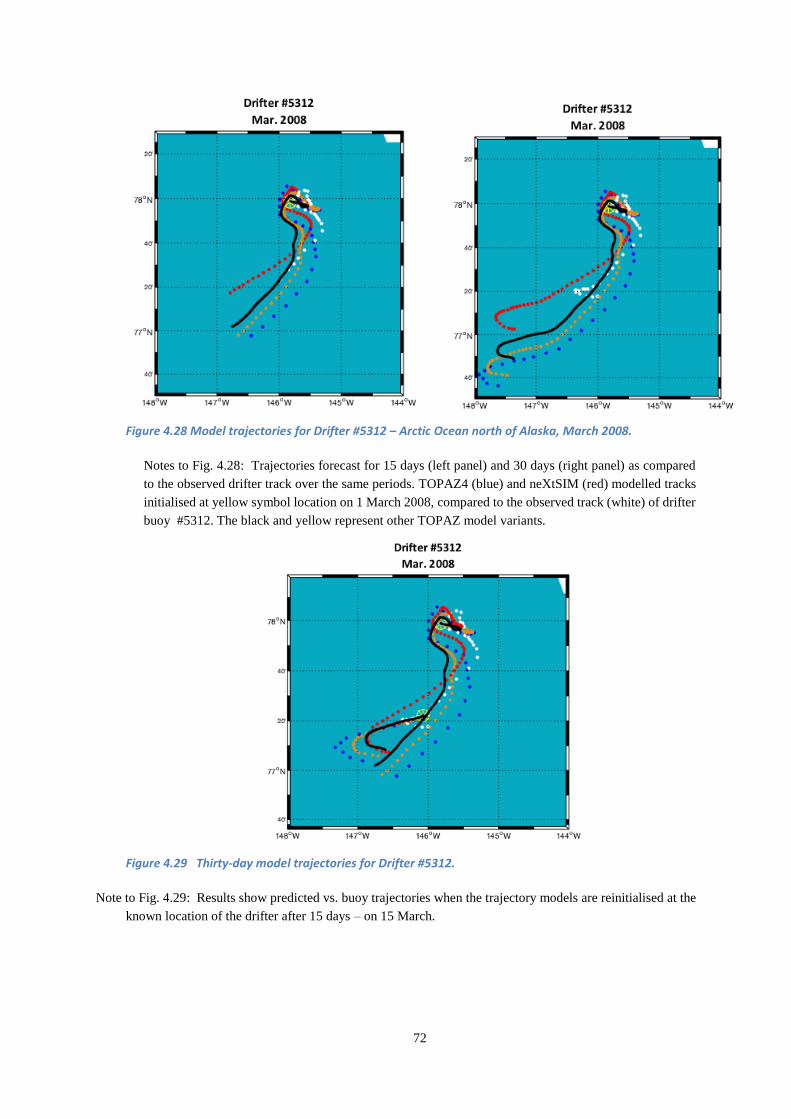
72
Figure 4.28 Model trajectories for Drifter #5312 – Arctic Ocean north of Alaska, March 2008.
Notes to Fig. 4.28: Trajectories forecast for 15 days (left panel) and 30 days (right panel) as compared
to the observed drifter track over the same periods. TOPAZ4 (blue) and neXtSIM (red) modelled tracks
initialised at yellow symbol location on 1 March 2008, compared to the observed track (white) of drifter
buoy #5312. The black and yellow represent other TOPAZ model variants.
Figure 4.29 Thirty-day model trajectories for Drifter #5312.
Note to Fig. 4.29: Results show predicted vs. buoy trajectories when the trajectory models are reinitialised at the
known location of the drifter after 15 days – on 15 March.

73
4.6.5 Trajectory Modelling Achievements
This JIP research program advanced oil spill trajectory modelling by supporting the further development
of a new, advanced coupled ice-ocean forecast model (neXtSIM) and integrating this model to better
predict surface oil transport in the two commonly used oil spill trajectory models commercially available,
OILMAP and OSCAR.
Most significantly, the JIP required that NERSC provide model output that is netCDF Climate Forecast
(CF) compliant, conforming to international conventions for model output file formats and data naming.
As a result, OSCAR and OILMAP are now able to use inputs from any coupled ice ocean model that
outputs data in this form. This will make integrating further new ice model data into the existing
operational oil spill fate and behaviour models much easier in the future. The oil spill modelling
community and responders now have greater flexibility in the variety of models they can use as well as
the ability to rapidly take advantage of new modelling technologies as they evolve.
Experience with this project reaffirmed that coordination is the key to successful use of the ice model
data with the oil spill trajectory models. Missing any data component (i.e., currents, ice and wind) in the
transfer creates unnecessary problems that can stretch available personnel resources, especially during
an actual incident where limited time is available to bring the modelling team up to full operational status.
4.7 Environmental Effects – Supporting NEBA
The overall goals of JIP research into the environmental effects of Arctic oil spills and the tools used to
mitigate impacts were to improve industry response preparedness while gaining increased stakeholder
acceptance of the role of environmental impact assessment in oil spill response planning and operations.
In achieving these goals the JIP aimed to improve the available knowledge base for using Net
Environmental Benefit Analysis (NEBA) in oil spill response decision-making. Improving access to
available literature and acquiring new data where necessary accomplished this.
The choice of response techniques for a specific spill must consider possible impacts of untreated oil on
one or more components of the ecosystem and compare the option of no action to possible impacts of oil
treated with one or more response techniques, for example using mechanical recovery, dispersants or in
situ burning. Using a structured NEBA approach (See 2.2.6) helps response managers choose a strategy
or mix of strategies that minimise the environmental impacts from a spill and facilitate a faster recovery
(IPIECA/IOGP, 2015).
The Environmental Effects research projects were aimed to improve the ability to efficiently access the
available, already extensive, science base needed to conduct a NEBA, while at the same time collecting
new data on the sensitivity and resiliency of sea ice biota, an important area receiving limited study in
the past. The projects are described in the following three sections:
1. Reviewing the available NEBA science base,
2. Collecting new field data along with related modelling and laboratory studies, and
3. Creating a web-based NEBA information and support tool.
4.7.1 Review of the NEBA science-base, key findings and recommendations
A consortium of international experts in the fields of Arctic food webs; behaviour of oil in surface waters,
at depth, and in ice; the effectiveness of oil spill response methods in cold-water surface and subsurface
environments; toxicology; and NEBA conducted a comprehensive review of the scientific literature.
Contributors to this process were affiliated with 14 North American and European research institutes and
universities. NewFields (WA-U.S.A) coordinated the review (Word, 2014).
This effort culminated in the online publication of a report “Environmental Effects of Spilled Oil and
Response Technologies in the Arctic” based on over 960 literature references from investigations into
74
spilled oil and oil spill response technologies in the Arctic marine environment:
http://neba.arcticresponsetechnology.org/report/
The report is the first unified compilation of the significant body of research on this area, confirming that
a large amount of literature is already available to aid informed oil spill response decision-making in the
Arctic. Nine chapters cover:
1. The Physical Environment
2. Arctic Ecosystems and Valuable Resources
3. The Transport and Fate of Oil in the Arctic
4. Oil Spill Response Strategies
5. Biodegradation
6. Ecotoxicology of Oil and Treated Oil in the Arctic
7. Population Effects Modelling
8. Ecosystem Recovery
9. Net Environmental Benefit Analysis for Oil Spill Response Options in the Arctic
For each category, the report provides priority research recommendations for enhancing Arctic NEBAs,
as well as other research considerations.
Key findings from the literature review are that:
There is already an extensive science base for Arctic NEBAs. Many baseline ecosystem and
biodiversity assessments exist to help us better understand and protect the marine Arctic
environment. Extensive data sets on oil fate and effects and spill response techniques are
available from field and laboratory studies representing the different seasonal conditions in the
Arctic.
There is clear evidence that Arctic species are no more sensitive to dispersed or undispersed oil
than non-Arctic species and that they react to dispersed oil exposure in the same way as
temperate species. To fully understand species impacts and recovery, the review recommended
follow-up work to study population resilience.
Data shows that approved dispersants and oils treated with dispersants are no more toxic than
the oil itself. Another important finding is that biodegradation of oil in the Arctic does occur
and that dispersants do not reduce the ability of microbes to degrade oil.
Biological organisms tend to aggregate at interfaces like the water/ice interface, which is one of
the unique features of the Arctic ecosystem. Undispersed oil might collect at this interface,
potentially interfering with unique Arctic biota. The review recommended acquiring
information on the potential effects of oil on these Arctic communities to better assess possible
impacts in NEBA. This led to a series of field mesocosm experiments (discussed below in 4.7.2).
The presence of ice can mitigate or delay the environmental impact of a spill, resulting in
reduced evaporation, dispersion and emulsification. Landfast ice can form an impermeable
barrier for much of the year, protecting vulnerable coastal resources. In addition, any oil
encapsulated in ice is isolated from marine life in the water column throughout the winter.
4.7.2 Sensitivity and Resilience of Ice Biota to Oil and Oil Spill Response Residues
The goal of this project was to improve scientific knowledge of the fate and biodegradation of oil and oil
spill response residues in ice, along with data on the sensitivity and resilience of ice associated ecology.
Permitted field experiments (approved by the Governor of Svalbard) using in situ mesocosms were
conducted to understand the oil weathering process and natural biodegradation of the oil under Arctic
conditions and to measure the sensitivity and resiliency of sea ice communities.

75
Note: A mesocosm is any outdoor experimental system that examines the natural environment under
controlled conditions. In this way mesocosm studies provide a link between field surveys and highly
controlled laboratory experiments.
A multidisciplinary team of experts examined the long-term fate, behaviour, persistence and
biodegradation of oil in ice together with the impacts on the microbial and plankton communities in and
under ice, focusing on three specific response scenarios:
1. Untreated oil,
2. Burn residue that could potentially remain floating on the surface close to freeze-up, and
3. Oil mixed with dispersant that could remain on the surface following an ineffective dispersant
application – i.e. oil that never dispersed. Note: this scenario is not the same as having already
dispersed oil potentially resurfacing after treatment. Research covering this separate topic is covered
in 4.4.1.
Eight 1.6 metre diameter, 3 metre long mesocosms installed in the sea ice of Van Mijen Fjord, Svea,
Norway in January 2015, remained in place until ice melt out in July 2015 (Fig. 4.30 & 31). Two
mesocosms contained oil only to follow the effects of natural attenuation (no response); two contained
dispersant mixed with oil at a standard dose rate of 1:20 ratio; two contained burned residues, and the
two remaining mesocosms served as controls (no oil). The use of these semi-open systems to study effects
of contaminants in open water marine systems is well established, but this technique had never been used
in Arctic ice environments. In all exposure mesocosms the amount of oil was kept constant (20 litres oil
or burn residue resulting from burning 20 litres of oil). In the mesocosm simulating natural attenuation,
20 litres oil resulted in a one cm slick, which could represent thick oil naturally contained among floes
just prior to or during freeze-up.
The field experiments spanned a single winter and spring season including the period of peak biological
activity. During the four-month study period researchers sampled and analysed the following parameters
in the water column, through the ice layer and within the water-ice interface: chemical composition of
the oil, total bacterial populations and oil degrading microorganisms, microbial activity and
biodegradation activity, zooplankton – survival, feeding and reproduction (under ice), and ice algae
primary production.
This was an international effort: Akvaplan-niva (Norway) led the work supported by a consortium of
research organizations from Denmark (DTU, COWI), France (CEDRE) Norway (IRIS, UiT, UNIS),
U.S.A (Bigelow Laboratory for Ocean Sciences), The Netherlands (IMARES) and Canada (Laval
University).
Akvaplan-Niva (2016) contains detailed descriptions of the experimental setup and results for the
environmental effects field programme.
Sampling included:
Ice cores for hydrocarbon chemistry and microbial response (Fig. 4.31 below)
Ice cores of the ice bottom to assess nutrients and chlorophyll levels related to ice algae
populations and production rates
Water samples below the ice and at the ice/water interface for hydrocarbon chemistry and to
sample and monitor under-ice phyto- and zooplankton communities

76
Source: CEDRE
Figure 4.30 Pictures of one of the mesocosms used in the Svea field-campaign.
Sampled water volumes from the mesocosms were transported to the laboratory at the University Centre
in Svalbard (UNIS) for to assess effects on zooplankton focussing on plankton reproduction. In addition,
dedicated experiments were designed to examine the sensitivity and resiliency of wild Polar cod to fresh
oil mixed in the water column in the laboratory at Tromsø. In the spring, effects on the biologically active
sea surface micro-layer from exposure to oil and oil residues were also studied through holes cut into the
ice.
Finally, modelling studies looked at the population effects on Polar cod and Arctic zooplankton to
provide guidance on the type of toxicity data crucial for NEBA decision-making. This activity aimed to
provide insights into assessing the added value of chronic toxicity data compared to the more readily
available acute toxicity data for NEBA based decision-making.
Figure 4.31 Coring through one of the mesocosms, March 2015
OGP-field sampling March 2015Coring
Frame to select position of cores in mesocosms

77
4.7.2.1 Hydrocarbon chemistry and Microbial response
For all treatments, changes to the chemical composition of the oil slick trapped in the top layer of the ice
were minimal, indicating that oil remained relatively fresh throughout the ice period and confirming
results from previous field studies (Norcor 1975; Dickins and Buist 1981; Brandvik et al. 2006). Minor
changes in alkane composition suggests that while not significant in terms of reducing overall spill
volume, some biodegradation and evaporation likely takes place while the oil is frozen into the top layer
of the ice.
Untreated oil (natural attenuation scenario) frozen into the ice upper surface displayed a slow dissolution
of soluble light polyaromatic hydrocarbons (PAHs) (i.e. naphthalene) into the ice and the water column
underneath the ice. Dispersant premixed with the oil enhanced this process. As expected in-situ burn
residues liberated only small concentrations of PAHs into the ice and not into the water, reflecting the
fact that most of the light components of the oil are burned off in the combustion process.
Arctic microbial communities in ice shift somewhat in response to oil within the first month of exposure.
Bacteria related to known oil biodegraders (Oleispira + Colwellia) were present and active in the sea-
ice layers for all the oiled mesocosms.
In summary, findings were positive in terms of oil spill response:
Oil trapped in ice undergoes minimal change over time. A fraction of the lightest compounds
(HAPs and alkanes) are dissolved and migrate down through the ice,
Microbial communities are active in Arctic waters and able to degrade petroleum compounds,
A higher number of microorganisms are found in the ice and seawater in presence of oil,
Microbial communities shift towards abundant oil-degrading organisms when exposed to oil,
and these changes happen faster in the presence of dispersant (a positive finding), and
Incubation experiments showed that bacteria present in sea ice were able to respond to and
degrade petroleum hydrocarbons.
4.7.2.2 Sea ice communities
Ice-algae
No evidence was found that the presence of oil in the upper layers of sea ice had an adverse impact on
nutrient availability in bottom ice. In addition the presence of oil at the ice surface had no effect on the
upward supply of nutrients from the water to the algal layer in the bottom few centimetres of the ice.
Under ice micro- and zooplankton
In winter, none of the considered oil treatments substantially affected the micro plankton communities
underneath the ice. However, in spring, the oil and dispersant mixture and natural oil attenuation
(untreated oil) affected the growth of several functional groups of plankton, potentially as a result of
lighter oil fractions leaching out of the ice and also reduced light conditions due to the oil layer frozen
into the ice. However, even a very large spill is unlikely to impact more than a small fraction of a
regional under ice eco-system. In addition, these communities are characterised by high resilience and
rapid recovery rates, resulting in a very low probability of ecosystem-wide impacts of any significance.
Residues of burnt crude oil had the least harmful effects on the microbial communities.
Polar Cod
Limited to no long-term effects on survival, growth or reproductive investment were revealed in Polar
Cod monitored in the lab for a period of 7 months after short duration exposure to mechanically dispersed
oil, chemically dispersed oil or residues of burnt oil.

78
Sea surface microlayer
Spring sampling through holes cut in the ice revealed no differences between the sea surface layer and
underlying water in terms of density of bacteria and Pico plankton (organisms 0.2-2 μm in
length)/Nanoplankton (organisms 2-20 μm in length) as well as bacterial community diversity, regardless
of the level of oil treatment. There was also no or little change observed in bacterial composition and
diversity within and among the various oil treatments, except for some known oil-degrading bacterial
species. The increase of oil degrading bacteria in the surface layer demonstrates that these organisms are
present and have the potential to respond to hydrocarbon input within time periods as short as one day.
4.7.2.3 Modelling
Modelling efforts for Polar cod and Calanus species showed that the lack of chronic toxicity data does
not necessarily hamper oil spill response decision-making. When no chronic data is available,
precautionary measures, like assuming a standard acute-to-chronic ratio (e.g. 1:10) and assuming 100%
mortality once the chronic effect level is exceeded, can result in gross overestimation of population
impacts. The modelling effort also showed that even relatively simple models could provide important
information to aid the risk assessments, which are traditionally based on simple risk characterisation
ratios.
4.7.3 Online NEBA Information and Support Tool
The overall goal of developing the Net Environmental Benefit Analysis (NEBA) information support
tool was to enhance access to the vast amount of existing data by NEBA practitioners by creating a web-
based searchable literature portal.
When oil is released into the marine environment, the priority for responders is to protect human health
and to minimise environmental impacts. From an environmental perspective, the selection of appropriate
response option(s) depends upon a wide range of information including data on the fate and behaviour
of oil and treated oil, the habitats and organisms that are potentially exposed, and the potential for effects
and recovery following exposure. NEBA and similar Comparative Risk Assessment (CRA) approaches
provide responders with systematic methods to compare and contrast the relative environmental and
social benefits and consequences of different response alternatives (IPIECA/OGP 2015).
Government and industry representatives have used this approach increasingly in temperate and
subtropical regions to establish environmental protection priorities and identify response strategies that
minimise impacts and maximise the potential for environmental recovery. Historically, the ability to
conduct NEBA-type assessments in the Arctic was limited by insufficient information relevant to oil-
spill response decision-making. However, with an increased interest in shipping and development in the
Arctic, a sufficiently robust scientific and ecological information base already exists in many Arctic areas
that can support meaningful NEBA.
The JIP developed a web portal to support conducting an Arctic NEBA. The portal provides access to a
summary of 3,500 literature references on Arctic ecosystems and the fate and effects of oil and treated
oil in the Arctic. Most importantly, the framework used to group the literature provides mimics the
structure of critical input parameters needed to conduct a NEBA evaluation, for example: Valued
Ecosystem Components, Response Strategy, and Resilience and Persistence (Gardiner et al., 2017).
http://neba.arcticresponsetechnology.org
The publicly available, fully searchable report and literature database enables rapid access to a wide
scientific knowledge base relevant to work aimed at minimising the environmental impacts of an oil spill
event in Arctic waters. The portal compiles technical and scientific reports identified by an international
consortium of Arctic and oil spill research scientists describing field studies and research pertinent to each
of four primary OSR alternatives currently considered viable in the Arctic environment – monitored
natural recovery, mechanical recovery, surface dispersant application and ISB.

79
Using this new tool, OSR planning and preparedness experts using NEBA for management and decision-
making can access information important for comparing different response strategies and estimating the
possible consequences to and recovery potential for the different environmental compartments and under
different environmental conditions.
4.7.4 Environmental Effects Research Achievements
Over the course of the environmental effects research programme, the JIP greatly advanced the ability to
apply NEBA at both a planning/assessment and operational decision-making level by:
1. Performing a comprehensive review of the environmental impacts arising from both the oil spill
itself and the countermeasures activities and identifying a number of research activities to
improve the knowledge base for using NEBA in the Arctic,
2. Conducting a series of modelling and laboratory studies and field data collection programmes
aimed at reducing remaining uncertainties on sensitivity and resiliency of sea ice communities
and oil biodegradation, and
3. Producing a NEBA information and support tool that identifies and summarises crucial data for
evaluating the ecological consequences of oil spill response options.
Results and findings from the field experiments suggest that:
Arctic bacterial populations are dominated by a few species that rapidly shift to hydrocarbon
degraders when presented with oil,
Oil degrading organisms are more abundant in the oil contaminated ice samples than in the
controls, particularly with the addition of dispersant to the oil,
Hydrocarbon levels in the water under the ice appear close to background when oil, oil and
dispersants or remains of burned oil become frozen into the ice surface, and
These trace hydrocarbon levels under the ice will have a limited effect on zooplankton
reproduction.
In summary, the JIP’s activities in this area successfully collected, reviewed and extended the science
available for Arctic NEBAs and produced a structure where this information is stored and easily
retrieved. Results from the field studies and the additional modelling activities have improved the
understanding of what happens to oil once frozen into ice, how microbiology is reacting to oil in ice and
what the exposure potential is of the ecology associated with the ice. This information and the developed
systems will help the response community in selecting a combination of response strategies that
minimises the effects to people and the environment.
Photo: United States Coast Guard


81
5 INSIGHTS AND CONCLUSIONS
This chapter outlines the key findings and results of the JIP and indicates how the programme improved
the ability to use existing response tools in a more effective and informed manner. In several areas, the
JIP created new strategies that expand the capabilities of already proven removal tools, for example aerial
herder application and ignition.
5.1 Arctic Spill Response as an Extension of Global OSR Practices
Response strategies for spills in ice use the same general suite of countermeasures, modified and adapted
for the conditions that are used elsewhere in the world. Other similarities are the use of Net
Environmental Benefit Analysis (NEBA) to ensure that the impacts of oil spills on people and the
environment are minimised; and the importance of having the flexibility to use the full range of available
countermeasures in the most effective manner to minimise damage to the environment. Response
strategies for Arctic spills in ice or open water follow the same tiered strategy used elsewhere in the
world (IPIECA-IOGP, 2015a). This approach uses a case-by-case assessment to decide whether to rely
on locally available response capability or to cascade additional capability from global storage locations.
There are both positive and challenging aspects of responding to spills in the presence of ice (EPPR,
2015). Working offshore anywhere in the world demands a high level of response preparedness as well
as supporting systems and trained and drilled personnel. The Arctic environment adds specific challenges
such as ice, cold, extended periods of darkness for part of the year and logistics constraints, while
moderating others such as sea state, weathering rates, and oil spreading. Several recent Arctic oil spill
response reviews expand on these differences in detail e.g. Potter et al. (2012), NPC (2015), and EPPR
(2015).
The following points highlight some of the established differences, both beneficial and constraining,
between Arctic and temperate climate oil spill response.
Potential positive factors are:
The wind and sea conditions in many Arctic areas are considerably less severe than most open
ocean environments, facilitating marine operations. The presence of any significant ice cover
dampens wave action and often limits the fetch over which winds might otherwise create larger
fully developed waves.
The colder temperatures and calmer seas coupled with the likelihood of thicker oil films in the
presence of ice, slows the weathering rate. Evaporation is reduced along with the rate of water
uptake (emulsion formation). These effects extend the time windows when strategies like ISB and
dispersant application are effective.
Ice can potentially contain, encapsulate and isolate oil from the marine environment for many
months, minimising immediate impacts and providing valuable additional time for planning and
executing a response when conditions are more favourable. This so called “deferred response”
option is rarely if ever available in the case of open water spills.
When ice concentrations preclude the effective use of traditional containment booms, the ice itself
often serves as a natural barrier to the spread of oil. The resulting smaller contaminated area not
only reduces the potential marine impacts but also limits the operational area that must be covered
by response crews.
The fresh condition of oil frozen into the ice, when exposed at a later date (e.g., through ice
management or natural oil surfacing through melting ice) enhances the likelihood of effective ISB
and/or dispersion in the spring.
The interaction of individual ice floes in intermediate ice concentrations can increase the available
natural mixing energy and promote successful dispersion. Where there is insufficient turbulence in
82
the upper water column, introducing mechanical mixing energy from vessels’ propellers can
effectively disperse the oil.
The fringe of landfast ice common to most Arctic shorelines acts as an impermeable barrier and
prevents oil spilled offshore at freeze-up from entering and contaminating coastal areas throughout
the long winter period.
Long periods of extended daylight during much of the summer exploration period increase the
operational time for response activities.
At the same time, there are a number of specific challenges associated with responding to spills in cold
water and ice, including:
Ice interference with traditional mechanical containment and recovery methods.
Potential gelling of some crude oils with pour points at or below 0°C.
Extended periods of winter darkness and low visibility.
The general lack of shore or marine base infrastructure in some Arctic areas.
Maintaining worker safety under conditions that may include extreme wind chill,
accelerated fatigue and icy deck surfaces for example.
The JIP focused on opportunities to increase response effectiveness in remote areas under a wide range
of offshore conditions while considering both the potential benefits and known challenges presented by
the full range of ice environments.
5.2 JIP Results for Arctic Oil Spill Response
As summarised in the preceding discussion (2.2), a demonstrated Arctic OSR capability existed at the
outset of the JIP regarding the fate and behaviour of oil under Arctic conditions and the applicability of
different response strategies in ice and cold ice-free water. Four decades of research into Arctic spill
response provided a strong baseline to help identify priority areas where new research could potentially
achieve the most significant advances in capability (3.2).
The following points contrast the understanding of five different aspects of Arctic oil spill response at
the outset of the JIP in 2012 and on JIP completion in 2017.

83
Dispersants in ice including subsea dispersant injection (SSDI):
2012
o Testing had demonstrated that dispersants are effective in high ice concentrations with the
addition of mechanical mixing energy. The previous SINTEF Oil in Ice JIP considerably
advanced the state of the art in this area, validating previous tank and basin testing by ExxonMobil
through field tests in the Norwegian Barents Sea in 2009 (Daling et al., 2010; Nedwed et al.
2007). There remained a need to understand dispersant effectiveness under different ice
conditions, and to model dispersed oil behaviour in different scenarios, including conditions
where oil resurfacing beneath the ice was a possibility, either following surface application from
vessels or aircraft, or from subsea dispersant injection (SSDI).
2017
Research findings from the JIP permit assessment of the behaviour of dispersed oil in a wide
range of Arctic offshore conditions. Variables tested include: oil type, dispersant type, water
salinity, turbulent energy level and ice concentrations. This information will improve future
contingency plans and lead to better real time response decisions based on scientific evidence of
how dispersants are likely to perform in different scenarios.
An existing model was extended to cover conditions of low water turbulence associated with
an ice cover. Field measurements provided missing data on under-ice turbulence. The study
results will help determine the acceptability of using dispersants in different oil and ice
scenarios by providing estimates of the resurfacing potential of dispersed oil under different
ice conditions, with and without the addition of mechanical mixing energy through
icebreakers.
An existing plume model was applied to predict the percentage of oil surfacing from a subsea
release and the subsequent persistence of surfaced slicks in different water depths (150 to
1,000 metres) and wind speeds, both with and without the application of SSDI. Graphical
results clearly show that under certain combinations of water depth and wind speed, there are
significant environmental benefits to using SSDI in reducing surface oil slick areas, and oil
film thickness. The reduced volume of less persistent oil on the surface reduces the exposure
risk to marine life while at the same time potentially resulting in lower surface volatile
organic compound (VOC) concentrations, improving the safety conditions for responders
and well control teams.
An existing modelling framework demonstrates that the use of dispersants in response to a
major incident would likely have no significant impact on fish populations. A highly
conservative estimation predicted effects on less than 0.07% of the regional Arctic Cod adult
population in the example used for the U.S. Beaufort Sea.
New field experiments followed by lab testing demonstrated that oil with and without
dispersant that is frozen in through the winter remains dispersible when released from the ice
the following summer. This finding has important implications for planning an effective
offshore response to oil in ice.
84
Burning oil on or among ice:
2012
o The use of ISB in a wide range of ice conditions was proven through multiple large-scale field
trials, basin and laboratory tests spanning four decades (Buist et al., 2013).
o Laboratory and basin tests showed the potential for herding agents to thicken oil slicks under
open drift ice conditions where slicks can quickly become too thin to ignite. Field experience with
herders was limited to a single project in the Norwegian Barents Sea in 2009 (Buist et al., 2010a).
More work was required to develop herding and burning into an operational tool. No system
existed for aerial application of herders and the concept of integrating herder and burning into a
single system was not considered. Research focused on using herders on spills among ice rather
than open water.
o Burning oil on the ice surface in the spring season was recognised as a scenario of interest dating
back to the early 1990s but the technology to reach locations far offshore was still limited by a
need to carry the Helitorch™ ignition source as a sling load, greatly reducing the helicopter’s
range. Ground tests demonstrated the feasibility of ejecting burning gelled fuel at higher
airspeeds and longer ranges from a fixed wing aircraft, but further work was needed to develop
the concept.
2017
JIP research in this area developed a new integrated aerial delivery system for herding and burning
slicks, expanded the application of herders to offshore open water environments, further evaluated
potential herder toxicity and produced a new engineering concept for a higher capacity, longer-
range aerial ignition system.
The implications are: a new rapid response capability independent from surface support,
improved effectiveness in responding to spills in remote areas, and improved confidence in
the operational performance and environmental acceptability of herders.
A new field trial offshore Norway in collaboration with NOFO and NCA provided additional
verification that herders could contract slicks for effective ignition in open water, adding to
the successful experience in a previous JIP with herders and burning in the presence of ice.
Laboratory tests with several Arctic species corroborated the view that in field applications,
low volumes of herders that rapidly spread to form a monolayer on the surface should pose
no significant risk to the environment in terms of their toxicity to or effects on selected
organisms (plankton, copepods, and seabird feathers).
Regulators and the responders in Alaska and Norway attended the JIP’s successful field trials
where they witnessed demonstrations of the potential of herding and burning as a new
combined response strategy for both ice covered and open water.
The conceptual design for a new long range aerial ignition system using fixed wing and rotary
wing aircraft has the potential to expand the use of ISB to offshore sites previously beyond
the range accessible by a helicopters carrying the Helitorch™.

85
Detection and Mapping:
2012
o Remote sensing systems proven in open water response operations such as during the Deepwater
Horizon Incident (Leifer et al., 2012) were considered applicable to some oil in ice scenarios.
However, these assumptions were based on limited direct experience and extrapolations of open
water performance to conditions such as very open drift ice (Dickins and Andersen, 2009). There
were positive results from Arctic field-testing with ground penetrating radar (GPR) but
operational applications were confined to areas with safe, stable ice covers capable of supporting
teams on the surface and/or certain scenarios amenable to low level airborne surveys, for example,
oil on the ice surface covered by snow (Bradford et al., 2010).
o AUV technology was expanding rapidly and viewed as a potentially useful platform to search for
oil under ice but validation of this concept was limited to a single successful test-basin experiment
with sonar, conducted in 2012 (Wilkinson et al., 2015).
o UAS technology was similarly undergoing a technology breakthrough and also seen as a basis
for future Arctic ice and oil spill surveillance platforms. However, operational implementation
was in the early stages.
o In general, development of specific remote sensing plans for an OSRP were hampered by a lack
of knowledge concerning the likely performance of different sensors in an actual Arctic field
setting.
2017
The results and recommendations of the JIP remote sensing research projects facilitate the
selection of the most effective remote sensing technologies to detect oil in, under, on and around
ice in the event of an actual spill.
As a result of JIP-sponsored test programmes, response managers now have a better
understanding of relative sensor capabilities, strengths and weaknesses in particular oil and
ice situations when using a range of different sensors above and below the ice. Variables
included oil film thickness, location of the oil layer within the ice sheet and situations with
free oil beneath the ice or on the surface during freeze-up.
The data collected in the JIP remote sensing test program was used to create a graphical field
guide that communicates the JIP research findings to responders at a practical operational
level. Dealing specifically with twelve different oil and ice scenarios, this is the first such
guide of its kind, complementing initiatives by IPIECA and others that summarise best
practices and available sensors for remote sensing in open water (Partington, 2014).

86
Environmental Effects:
2012
o NEBA was widely recognised as the best scientific method to compare the environmental benefits
of potential response tools and develop a response strategy that will reduce the impact of an oil
spill on the environment (IPIECA-IOGP, 2015).
o There was already an extensive environmental science base available for Arctic NEBA with many
baseline ecosystem and biodiversity assessments. Extensive data sets on oil fate and effects and
spill response techniques were available from field and laboratory studies. However, no organised
repository of environmental effects data existed to facilitate the application of NEBA in an Arctic
setting.
o Limited knowledge existed on the potential effects of oil frozen or trapped within the ice on the
sea ice ecosystem.
o There was clear evidence that Arctic species are no more sensitive to dispersed or undispersed oil
than non-Arctic species and that they react to dispersed oil exposure in the same way as temperate
species.
o Data showed that approved dispersants and oils treated with dispersants are no more toxic than
the oil itself. Another important finding was that biodegradation of oil in the Arctic does occur
and that dispersants do not reduce the ability of microbes to degrade oil (Gardiner et al., 2013).
2017
The JIP’s activities in this area reviewed and extended the available science base on oil spill
impacts in an Arctic environment, and produced a web-based literature access tool where this
information is stored and easily retrieved. Results from laboratory and field tests, and modelling
studies improved the understanding of what happens to oil once frozen into ice, how microbiology
reacts to oil in ice and what the exposure potential is of sea ice ecosystems. This information will
provide valuable new data to support NEBA.
A new literature access navigation portal directs response managers and planners to the most
relevant literature needed to assess specific environmental effects of an Arctic oil spill when
using different response strategies, including natural attenuation. The literature navigator
organises 3,500 references using a framework based on NEBA principles such as: Valued
Ecosystem Components (VEC) exposure, sensitivity and resiliency in different
environmental compartments (water surface, atmosphere, and water column). This tool will
lead to improved contingency plans by allowing planners and responders to efficiently access
the information needed to effectively apply NEBA.
New data cover the effects of oil and dispersants on under-ice biota, weathering of oil in ice,
and oil biodegradation rates. This work filled an important gap in the overall knowledge of
the potential significance of oil impacts in an ice environment. In general, the results
demonstrated no significant environmental effects on the sea ice ecosystem as a result of oil,
oil mixed with dispersant or ISB residue frozen into the ice surface at freeze up and left
through the winter.

87
Trajectory Modelling:
2012
o The current generation of oil spill models could predict the behaviour of oil and its likely fate in
ice environments (degree of evaporation, rate of emulsification, etc.), but at the outset of the JIP
in 2012, they had limited capabilities to model oil movements in the presence of a significant ice
cover. This deficiency resulted from a combination of: 1) the limited resolution offered by the
existing ice models, and 2) the inability of the existing oil spill trajectory models to efficiently
import and process data from the available ice models.
2017
The JIP supported the development of several improved higher-resolution ice drift models that
outperform existing models both in pack ice environments with high ice concentrations and more
dispersed dynamic ice associated with Marginal Ice Zones (MIZ).
By requiring that the ice model outputs be provided in internationally accepted data exchange
formats, the two most commonly used oil fate and behaviour models – OSCAR and OILMAP –
can now efficiently import the data produced by a variety of available ice models to provide more
accurate predictions of oiled ice movements in a range of ice conditions.
Mechanical Recovery:
2012 - 2017
o The JIP assessed the technical feasibility and potential benefits of developing novel new
mechanical recovery concepts. The conclusion was that substantial improvements through design
and engineering were unlikely. Utilising technological advances in other fields could prove more
beneficial, for example making better use of remote sensing to more effectively direct vessels and
crews on the surface to areas with the most concentrated oil.
5.3 Key Outcomes and Implications of the JIP’s Work
The overall goal of spill response is to control the source as quickly as possible, minimise the potential
damage caused by an accidental release, and employ the most effective response tools for a give incident.
Giving responders the flexibility to apply the most effective “tools in the toolbox” to suit the prevailing
conditions, is the key to mounting a successful response and minimising impacts to the marine
environment.
The ultimate goal of the JIP was to further improve available response “tools in the toolbox” and to
extend their capabilities with new strategies, systems and a better understanding of operating windows
when a given response tool is likely to be effective. The JIP achieved this goal, as evidenced by the
results summarised in Chapter 4 and comparisons of response capabilities before and after the JIP (5.2).
Building on the extensive history of Arctic oil spill research (2.2), this JIP improved capabilities in many
different aspects of spill response, for example:
o Developing aerial herder application and ignition systems to expand opportunities to use ISB,
o Modelling the effectiveness of dispersants applied from the surface and subsea,
o Designing a unique literature portal to facilitate NEBA,
o Assessing the performance of different sensors to detect oil from above and below the ice,
o Integrating available oil fate and behaviour models with improved ice models.
Advances made under this JIP are underpinned by peer-reviewed science and full transparency in
making the results available to a wide audience through the reports, conference papers and journal

88
articles, listed in Chapter 7 and available for download at:
http://www.arcticresponsetechnology.org/publications-data
A broad cross section of users can apply the results of this JIP to planning, preparedness and response
execution. Key outcomes from the JIP results are:
o State of knowledge reports on key oil-in-ice response topics such as remote sensing, dispersants,
ISB and environmental effects synthesise critical information gained over more than 40 years.
o New data on response effectiveness in different conditions informs decision-making at all levels
from planning through to response.
o The environmental effects database and literature navigator facilitates the use of NEBA by
reducing the effort to identify and access the known, relevant information. This will lead to a
better understanding of the potential environmental effects of selecting different response
strategies.
o Better defined windows of opportunity and new data on expected response effectiveness for
strategies involving dispersants, herders and burning will improve contingency planning and
enable more realistic training courses, drills and exercises to maintain and develop responder
skills.
o Results of the dispersant research show the relative benefits of SSDI in a range of water depths
and wind speeds. These results will assist government and industry decision-makers in assessing
whether or not to incorporate this tool as part of oil spill response plans.
o More effective remote sensing supported by trajectory modelling will help responders to better
detect, track and map oiled area extent and movements.
o A practical field operations guide to remote sensing of oil in ice will help responders identify
the most effective mix of sensors and platforms to suit a particular Arctic spill scenario.
o New response tools such as aerial herder/burn systems enable rapid response to remote spill
locations without being dependent on marine support.
o The JIP results inform the public on many important topics involved in any discussion of Arctic
oil spill response. This transfer of information is supported by public availability of reports and
on line access to all of the material produced by the JIP including state-of-the-art technology
reviews, technical reports, peer-reviewed papers, videos and graphics.
o The rigorous scientific process followed by the JIP should provide greater levels of confidence
in Arctic oil spill response capabilities.

89
Norwegian Oil on Water Exercise 2016. Photo: D. Dickins


91
6 OPPORTUNITIES FOR CONTINUAL ADVANCEMENT
The JIP during its five-year course continually looked for new research and technology opportunities that could
add value to the original suite of projects as results came in. This feedback forms a natural progression in extending
the research boundaries in any field. The same process will continue in the future as industry, academia and
government scientists and engineers develop new oil spill research projects and ideas that build on and extend the
JIPs results.
Examples are listed below, focusing on opportunities to affect major advances in OSR capabilities through
operational evaluation and implementation of new response tools, technologies and strategies:
Experimental field releases in and around ice incorporating for example:
o Demonstration of response strategies using icebreakers in conjunction with dispersant
application.
o Field-testing of the integrated herder/burn system.
o Testing sensors over oil in natural ice.
Testing of sensor packages optimised for oil in ice detection and mapping with UAS and AUV/ROV
platforms.
Develop operational, reliable UAS systems with sufficient payload capacity and endurance to apply
herders and ignite spills in ice and at sea.
Proof of concept testing of a long-range airborne ignition system as the next step to an operational
prototype.

92
7 REFERENCES AND BIBLIOGRAPHY
External to the JIP
Alaska Regional Response Team (ARRT). 2008. In-Situ burning Guidelines for Alaska: Revision 1. Appendix II,
Annex F, in The Alaska Federal/State Preparedness Plan for Response to Oil and Hazardous Substance
Discharges/Releases.
Allen, A.A. 1990. Contained controlled burning of spilled oil during the Exxon Valdez oil spill. Proceedings of
the 13th Arctic and Marine Oilspill Program (AMOP) Technical Seminar, Environment Canada, Ottawa. pp.
305-313.
Allen, A.A. 1987. Test and evaluation of the helitorch for the ignition of oil slicks. Proceedings of the 10th Arctic
and Marine Oilspill Program (AMOP) Technical Seminar, Environment Canada, Ottawa. pp. 243-265.
Allen A.A., D. Jaeger, N.J. Mabile, and D. Costanzo. 2011. The use of controlled burning during the Gulf of
Mexico Deepwater Horizon MC-252 oil spill response. Proceedings 2011 International Oil Spill
Conference, 13 pp.
Alpers, W. and Huhnerfuss, H., 1989. The damping of ocean waves by surface films: a new look at an old
problem, Journal of Geophysical Research, Vol. 94, No. C5, pp. 6251-6265.
AMAP (2007). Arctic Oil and Gas 2007. Report to the Arctic Monitoring and Assessment Programme (AMAP).
Oslo, Norway.
API/IPIECA/IOGP 2016. Guidelines on Implementing Spill Impact Mitigation Assessment, SIMA. API.
Washington DC
Bergstrøm, R. 2012. Lessons learned - the Godafoss accident in Feb. 2011: Oil spill recovery at -20°C.
Proceedings Interspill Conference, London.
Bouillon, S. and P. Rampal. 2015. Presentation of the dynamical core of neXtSIM, a new sea ice model. Ocean
Modelling, 91, pp. 23–37.
Bradford, J. H., D.F. Dickins and P.J. Brandvik. 2010. Assessing the potential to detect oil spills in and under
snow using airborne ground-penetrating radar. Geophysics, 75(2).
Brandvik, P.J., O. Johansen and U. Farooq. 2013. Droplet breakup in subsea oil releases – Part 1: Experimental
study of droplet breakup and effectiveness of dispersant injection. Marine Pollution Bulletin 73(1): 319-
326.
Brandvik, P.J., and T. Buvik. 2009. Using dogs to detect oil hidden in snow and ice--results from field training
on Svalbard, April 2008. SINTEFJIP Report No. 14, http://www.sintef.no/Projectweb/JIP-Oil-In-
Ice/Publications/
Brandvik, P.J. and L-G Faksness. 2009.bnWeathering processes in arctic oil spills: Meso-scale experiments with
different ice conditions. Cold Regions Science and Technology 55: 160-166.
Brandvik, P.J., L-G Faskness, D.F. Dickins and J. Bradford. 2006. Weathering of oil spills under arctic conditions:
field experiments with different ice conditions followed by in-situ burning. Presented at the 2006 Third
Annual NATO/CCMS Oil Spill Response Workshop, Oct 11-13, Dartmouth, NS, Canada.
Brandvik PJ, K-R Sørheim, I. Singsaas and M. Reed. 2006. Short state-of-the-art report on oil spills in ice-infested
waters: Oil behaviour and response options. SINTEF report STF80MKA06148, 59 pp.
Brandvik, P. J., O. O. Knudsen, M. O. Moldestad and P. S. Daling. 1995. Laboratory testing of dispersants under
Arctic conditions. American Society for Testing and Materials, Special Technical Publication (1252): 191-
206.

93
Bronson, M., E. Thompson, F. McAdams and J. McHale. 2002. Ice effects on barge-based oil spill response
systems in the Alaskan Beaufort Sea. Proceedings 25th Arctic and Marine Oilspill Program Technical
Seminar (AMOP), Environment Canada, Ottawa,pp. 1253-1268.
Brown, H. M. and R. H. Goodman. 1996. The use of dispersants in broken ice. Proceedings of the Nineteenth
Arctic and Marine Oilspill Program (AMOP) Technical Seminar, Environment Canada, Ottawa.
Brunila, O-P., and J. Storgard. 2013. Changes in oil transportation in 2020 and 2030 case studies: Gulf of Finland.
Proceedings IAME Conference, Marseilles France.
Buist, I., Potter, S., Nedwed, T., Mullin, J. 2011. Herding surfactants to contract and thicken oil spills in pack ice
for in situ burning. Cold Regions Science and Technology, 67, 1–2: 3–23.
Buist I.A., S. Potter, T. Nedwed and J. Mullin. 2011. Herding surfactants to contract and thicken oil spills in pack
ice for in situ burning. Cold Regions Science and Technology 67: 3–23.
Buist, I., S. Potter, and S.E. Sørstrøm, S.E. 2010a. Barents Sea field test of herder to thicken oil for in situ burning
in drift ice. Proceedings 33rd AMOP Technical Seminar on Environmental Contamination and Response,
Environment Canada, Ottawa, pp. 725-742.
Buist, I., G. Canaveri and T. Nedwed. 2010b. New herding agents for thickening oil slicks in drift ice for in-situ
burning. Proceedings of the Thirty-third AMOP Technical Seminar on Environmental Contamination and
Response, Environment Canada, Ottawa, pp. 1085-1108.
Buist, I., S. Potter, R. Belore, A. Guarino, P. Meyer and J. Mullin. 2010c. Employing chemical herders to improve
marine oil spill response operations. Proceedings of the Thirty-third AMOP Technical Seminar on
Environmental Contamination and Response, Environment Canada, Ottawa, pp. 1109-1134.
Buist, I., R. Belore, D. Dickins, A. Guarino, D. Hackenburg, and Z. Wang. 2009. Empirical weathering properties
of oil in ice and snow. Proceedings 32nd AMOP Technical Seminar, Vol. 1, Ottawa, pp. 629-648.
Buist, I., Dickins, D., Majors, L., Linderman, K., Mullin, J., Owens, C. 2003. Tests to determine the limits to in-
situ burning in brash and frazil ice. Proceedings 26th Arctic and Marine Oilspill Program Technical Seminar,
Environment Canada, Ottawa, 20 pp.
Buist, I.A., S.L. Ross, B.K. Trudel, E. Taylor, T.G. Campbell, P.A. Westphal, M.R. Myers, G.S. Ronzio, A.A.
Allen and A.B. Nordvik. 1994. The Science, Technology and Effects of Controlled Burning of Oil Spills at
Sea. MSRC Technical Report Series 94-013, Marine Spill Response Corporation, Washington, DC, 382 pp.
Buist, I., and D.F. Dickins. 1987. Experimental spills of crude oil in pack ice. Proceedings 1987 International Oil
Spill Conference. American Petroleum Institute. Washington, pp. 373-381.
Chapman P.M and M.J. Riddle. 2005. Polar marine toxicology—future research needs Mar Pollut Bull. 50: 905-
908.
Chapman P.M., Riddle M.J. 2003 Missing and needed: polar marine ecotoxicology. Mar Pollut Bull. 46(8): 927-
8.
Colony, R. and A.S. Thorndike. 1985. Sea ice motion as a drunkard’s walk, J. Geophys. Res., 90: 965–974.
Coon, M. D. 1974. Mechanical behaviour of compacted Arctic ice floes, J. Pet. Technol., 26: 466–470.
Daling, P., P.J. Brandvik, F. Leirvik, A. Holumsnes, and C. Rasmussen. 2010. Development and field testing of a
flexible system for application of dispersants to oil spills in ice. Proceedings 33rd Arctic and Marine Oilspill
Program (AMOP) Technical Seminar, Environment Canada, Ottawa, pp. 787-814.
Daling, P. S., P. J. Brandvik, D. Mackay and O. Johansen. 1990. Characterization of crude oils for environmental
purposes. Oil and Chemical Pollution 7(3): 199-224.

94
Dickins, D.F. 2011. Behaviour of oil spills in ice and implications for arctic spill response. Paper No. OTC22126,
Proceedings 2011 Arctic Technology Conference, Houston, TX..
Dickins, D.F. 2000. Detection and Tracking of Oil Under Ice. Report prepared for the US Department of Interior,
Minerals Management Service, Herndon, VA.
Dickins, D.F., and J.H.S. Andersen. 2009. Remote Sensing Technology Review and Screening. Oil in Ice JIP
Report 22. SINTEF Materials and Chemistry, Marine Environmental Technology, Trondheim, Norway.
Dickins, D.F., P.J. Brandvik, J. Bradford, L-G Faksness, L. Liberty and R. Daniloff. 2008. Svalbard 2006
experimental oil spill under ice: Remote sensing, oil weathering under Arctic conditions and assessment
of oil removal by in-situ burning. Proceedings 2008 International Oil Spill Conference, American
Petroleum Institute, Washington, DC.
Dickins, D., Buist, I. 1999. Oil spill countermeasures for ice covered waters. Journal of Pure and Applied
Chemistry, Vol. 71, No 1, London.
Dickins, D.F., Buist, I.A. 1981. Oil and Gas Under Sea Ice Study: Vols. I &2. Prepared by Dome Petroleum Ltd.
for COOSRA, Report CV-1, Calgary, AB, Canada. (also published in Proceedings 1981 International Oil
Spill Conference, Atlanta.GA)
EPPR Working Group. 2017 (update). Field Guide for Oil Spill Response in Arctic Waters. Prepared by Owens
Coastal Consultants, DF Dickins Associates and Counterspil Research Inc. for the Arctic Council, Tromso,
Norway
EPPR Working Group. 2015. Guide to Oil Spill Response in Snow and Ice Conditions in the Arctic. Prepared by
Owens Coastal Consultants and DF Dickins Associates for the Arctic Council, Tromso Norway, 184 pp.
Etkin, D. S. 2009. Analysis of US Oil Spillage, American Petroleum Insitute, Washington, DC.
Fingas, M.F., and C.E. Brown. 2011. Oil spill remote sensing: A review. Oil Spill Science and Technology, edited
by M. Fingas. Gulf Professional Publishing, Burlington, MA, pp. 111-158.
Fingas, M.F., G. Halley, F. Ackerman, R. Nelson, M.C. Bissonnette, N. Laroche, Z. Wang, P. Lambert, K. Li, P.
Jokuty, G. Sergy, W. Halley, J. Latour, R. Galarneau, B. Ryan, P.R. Campagna, R.D. Turpin, E.J. Tennyson,
J. Mullin, L. Hannon, D. Aurand and R. Hiltabrand. 1995. The Newfoundland offshore burn experiment.
Proceedings 1995 International Oil Spill Conference, American Petroleum Institute. Washington, DC, pp.
123-132.
Gardiner, W.W., et al. 2013. The Acute Toxicity of Chemically and Physically Dispersed Crude Oil to Key Arctic
Species Under Arctic Conditions During the Open Water Season. Environmental Toxicology and Chemistry,
32(10): 2284-2300.
Goodman, R. 2008. Oil Under Ice Detection – What is the State of the Art?. Oil Spill Response: A Global
Perspective, Springer, Hauten, Netherlands, pp. 7-19.
Hibler, W. D., III. 1979. A dynamic thermodynamic sea ice model. J. Phys.Oceanogr. 9: 815–846.
Hirche H., Mumm N. 1992. Distribution of dominant copepods in the Nansen Basin, Arctic Ocean, in summer.
Deep Sea Res 39: 485–505
Hirvi, J.P., R. Hakala, and J. Rytkonen. 1987. Study of Crude Oil Behaviour in Sub-Arctic Brackish Waters.
Report by the Finnish National Board of Waters and the Environment, Helsinki.
Hovland, M. 1992. Hydrocarbon seeps in northern marine waters -- their occurence and effects. Palaios 7: 378-
382.
IHS. Sept 3, 2014. International E&P Database.

95
International Energy Outlook 2016. Prepared by U.S. Energy Information Administration
http://www.eia.gov/outlooks/ieo/
IPIECA-IOGP. 2015a. Tiered Preparedness and Response: Good Practice Guidelines for Using the Tiered
Preparedness and Response Framework. IOGP Report 526, London, UK, 44 pp.
http://www.oilspillresponseproject.org/wp-
content/uploads/2017/01/Tiered_preparedness_and_response_2016.pdf
IPIECA-IOGP. 2015. Response Strategy Development Using Net Environmental Benefit Analysis (NEBA).
London, UK. http://www.oilspillresponseproject.org/wp-content/uploads/2016/02/GPG-Net-Environmental-
Benefit-Analysis.pdf
Johansen, O., P.J. Brandvik, and U. Farooq. 2013. Droplet breakup in subsea oil releases – Part 2: Predictions of
droplet size distributions with and without injection of chemical dispersants. Marine Pollution Bulletin
73(1): 327-335.
Kvenvolden, K. A. 2003. Natural Seepage of Crude Oil into the Marine Envrionment. GeoMarine Letters 23:
140-146.
Lampela, K. 2007. Baltic approach to oil spill recovery in ice: case studies and recent development in Baltic Sea
States. Proceedings 2007 International Oil & Ice Workshop. Minerals Management Service. Herndon, VA.
Lee, K., T. Nedwed, R. C. Prince and D. Palandro. 2013. Lab tests on the biodegradation of chemically dispersed
oil should consider the rapid dilution that occurs at sea. Mar Pollut Bull 73 (1): 314-318.
Lee, K., Z. Li, B. Robinson, P.E. Kepkay, M. Blouin, and B. Doyon. 2011. Field trials of in-situ oil spill
countermeasures in ice-infested waters. 2011 International Oil Spill Conference, Portland, Oregon.
American Petroleum Institute, Washington, DC, 16 pp.
Leifer, I., W.J. Lehr, D. Simecek-Beatty, E. Bradley, R. Clark, P. Dennison, H. Yongxiang, S. Matheson, C.E.
Jones, B. Holg, M. Reif, D. A. Roberts, J. Sveikovsky, G. Swayze, and JI. Wozencraft. 2012. State of the
art satellite and airborne marine oil spill remote sensing: Application to the BP Deepwater Horizon incident
oil spill. Elsevier. Remote Sensing of Environment 124: 185-209.
Lewis, A., D. V. Aurand and A. P. Institute. 1997. Putting Dispersants to Work : Overcoming Obstacles. Issue
Paper in Proceedings 1997 International Oil Spill Conference, American Petroleum Institute, Washington,
DC.
MacFadyen, A., G.Y. Watabayashi, C.H. Barker and C.J. Beegle-Krause. 2011. Tactical modelling of surface oil
transport during the Deepwater Horizon incident spill response. In Modelling and Monitoring the Deepwater
Horizon incident Oil Spill: A Record Breaking Enterprise. American Geophysical Institute, Geophysics
Monograph, pp. 167-178.
MacNaughton SJ, Swannell R, Daniel F, Bristow L. 2003. Biodegradation of dispersed Forties crude and Alaskan
North Slope oils in microcosms under simulated marine conditions. Spill Sci Technol Bull. 2003; 8:179–
186.
Margesin, R. and F. Schinner. 2001. Biodegradation and bioremediation of hydrocarbons in extreme
environments. Applied Microbiology and Biotechnology 56: 650-663.
McFarlin KM, Prince RC, Perkins RA, Leigh MB. 2014. Biodegradation of dispersed oil in arctic seawater at -
1C. PLOS One Volume 9, Issue 1.
McMinn, T.J. 1972. Crude Oil Behaviour on Arctic Winter Ice: Final Report. Office of Research and
Development, United States Coast Guard, Project 734108, Wash. D.C., NTIS Publication No. AP-754, 261
p. (also published as McMinn, LTJG T.J. 1973. Oil Spill Behaviour in a Winter Arctic Environment. In
Proceedings Offshore Technology Conference, Houston, TX.)

96
McPhee, M. 2008. Air-Ice-Interaction: Turbulent Ocean Boundary Layer Exchange Processes. Springer
Science, 215 pp.
Meyer P. 2014. Testing of oil recovery skimmers in ice at Ohmsett, the National Oil Spill Response Research &
Renewable Energy Test Facility. Proceedings of the International Oil Spill Conference, American
Petroleum Institute, Wash. DC.
NEB (National Energy Board). 2011. Arctic Offshore Drilling Review. Public Review of Arctic Safety and
Environmental Offshore Drilling Requirements. Ottawa, Canada.
Nedwed, T. 2017. Overview of the American Petroleum Institute (API) Joint Industry Task Force Subsea
Dispersant Injection Project, Proceedings 2017 International Oil Spill Conference (In Press), American
Petroleum Institute, Washington, DC.
Nedwed, T., R. Belore, W. Spring and D. Blanchet. 2006. Basin-scale testing of ASD icebreaker enhanced
chemical dispersion of oil spills Volume 1. Proceedings of the 30 Arctic and Marine Oilspill Program
(AMOP) Technical Seminar, Canada, Environment Canada, pp. 151-160
Nedwed, T., J. L. M. Resby and J. Guyomarch. 2006. Dispersant effectiveness after extended low-energy soak
times. Proceedings 2006 International Conference for Spill Prevention, London, UK.
Nelson, William G. and A. A. Allen. 1982. The physical interaction and clean-up of crude oil with slush and solid
first year sea ice. Proc. Fifth Arctic and Marine Oil Spill program Technical Seminar. Environment Canada.
Ottawa.
NPC (National Petroleum Council). 2015. Arctic Potential: Realizing the Promise of U.S. Arctic Oil and Gas
Resources. Submitted to the Secretary of Energy, Washington, DC.
NPC (National Petroleum Council). 2015. Toxicity of Oil to Arctic Organisms and Natural Oil Biodegradation.
Working Paper #8-8 prepared by the Technology and Operations Subgroup for the NPC Study: Arctic
Potential – Realizing the Promise of Arctic Oil and Gas Resources.
Norcor. 1975. The Interaction of Crude Oil with Arctic Sea Ice. Beaufort Sea Project Technical Report No. 27,
Canadian Department of Environment, Victoria, BC, Canada.
NRC (National Research Council). 2014. Responding to Oil Spills in the U.S. Arctic Marine Environment. The
National Academies Press, Washington, DC. 195 pp.
NRC (National Research Council). 2005. Oil Spill Dispersants: Efficacy and Effects. The National Academies
Press, Washington, DC.
OGP and IPIECA. 2012. Current Status and Future Industry Needs for Aerial Dispersant Application. London,
UK.
O’Hara and Morandin, 2010, Effects of sheens associated with offshore oil and gas development on the feather
microstructure of pelagic seabirds, Marine Pollution Bulletin, 60: 672-678.
Olsen, G. H., E. Sva, J. Carroll, L. Camus, W. De Coen, R. Smolders, H. Øveraas and K. Hylland. 2007.
Alterations in energy budget of Arctic benthic species exposed to oil related compounds. Aquat Toxicol. 83:
85-92
Owens, C. K. and R. S. Belore. 2004. Dispersant effectiveness testing in cold water and brash ice. Proceedings
of the 27th Arctic and Marine Oilspill Program (AMOP) Technical Seminar, Environment Canada, Ottawa.
Palandro, D., T. Nedwed, L. Srnka, H. Thomann and E. Fukushima. 2013. Using nuclear magnetic resonance in
the earth’s magnetic field to detect oil under ice. Proceedings of the 36th AMOP Technical Seminar on
Environmental Contamination and Response, Environment Canada, Ottawa.
Partington, K. 2014. An Assessment of Surface Surveillance Capabilities of Oil Spill Response Using Airborne
Remote Sensing. Report prepared for IPIECA-IOGP, London, UK.

97
Potter, S. and I. Buist. 2010. In-situ Burning in Arctic and Ice-covered Waters: Tests of fire-resistant booms in
low concentrations of drift ice. Proceedings 33rd Arctic and Marine Oilspill Program Technical Seminar,
Environment Canada, Ottawa, pp. 743-754.
Potter, S., I. Buist, K. Trudel, D. Dickins and E. Owens. 2012. Spill Response in the Arctic Offshore. Prepared
for the American Petroleum Institute and the Joint Industry Programme on Oil Spill Recovery in Ice, D.
Scholz (ed.). American Petroleum Institute, Washington. 157 pp.
Potter S., M. Bronson, E. Thompson, and L. Majors. 2007. Testing of various options for improving the pumping
of viscous oils and emulsions. Proceedings 30th Arctic and Marine Oilspill Program Technical Seminar,
Environment Canada, Ottawa.
Preli, T., A.A. Allen, and D. Glenn. 2011. Development of high-speed aerial ignition techniques for in situ
burning. Proceedings 2011 Arctic Technology Conference.
Prince, R. and J. Butler. 2014. A protocol for assessing the effectiveness of oil spill dispersants in stimulating
the biodegradation of oil. Environmental Science and Pollution Research 21(16): 9506-9510.
Prince, R. C. and J. R. Clark. 2004. Bioremediation of marine oil spills. Studies in Surface Science and
Catalysis, Elsevier B. V.: 495 – 512.
Pritchard, R. S. 1975. An elastic-plastic constitutive law for sea ice. J. Appl. Mech., 42; 379–384.
Rabatel, M., S. Labbé, and J. Weiss. 2015. Dynamics of an assembly of rigid ice floes, Journal of Geophysical
Research Oceans, 120, 5887–5909.
Rampal, P., S. Bouillon, E. Olason, and M. Morlighem. 2015. neXtSIM: a new Lagrangian sea ice model. The
Cryosphere Discussions, 9: 5885–5941.
Rampal, P., Weiss, J., Marsan, D., and Bourgoin, M. 2009. Arctic sea ice velocity field: General circulation and
turbulent- like fluctuations, J. Geophys. Res.-Ocean. 114, 17 pp.
Schmidt, B., P. Meyer and S. Potter. 2014. Testing of Oil Recovery Skimmers in Ice at Ohmsett. Proceedings
37th AMOP Technical Seminar on Environmental Contamination and Response, Environment Canada,
Ottawa.
Sergy, G. A. and P. J. Blackall. 1987. Design and Conclusions of the Baffin Island Oil Spill Project. Arctic Vol.
40 Supplement 1, pp. 1-9.
Shigenaka, G. 2014. Twenty-Five Years After the Exxon Valdez Oil Spill: NOAA’s Scientific Support,
Monitoring, and Research. Seattle: NOAA Office of Response and Restoration. 78 pp.
Singsaas, I., P.J. Brandvik, P.S. Daling, M. Reed, and A. Lewis. 1994. Fate and behaviour of oils spilled in the
presence of ice - A comparison of the results from recent laboratory, meso-scale flume and field tests.
Proceedings 17th Arctic and Marine Oilspill Program Technical Seminar, Vol. 1, pp. 355-370. Environment
Canada, Ottawa.
SL Ross Environmental Research. 2012. Research on Using Oil Herding Agents for Rapid Response In Situ
Burning of Oil Slicks on Open Water. Report to U.S. Department of the Interior, Bureau of Safety and
Environmental Enforcement, Herndon, VA.
SL Ross Environmental Research. 2010. Evaluation of the Crucial Coated-Disk Skimmer in Arctic Conditions.
Report to Alaska Clean Seas.
Sørstrøm, S.E., P.J. Brandvik, I. Buist, P. Daling, D. Dickins, L-G Faksness, S. Potter, J.F. Rasmussen, I. Singsaas.
2010. Joint Industry Program on Oil Spill Contingency for Arctic and Ice-covered Waters: Summary Report.
Oil in Ice JIP Report No. 32, SINTEF, Trondheim, Norway. www.sintef.no/Projectweb/JIP-Oil-In-
Ice/Publications/

98
Spring, W., T. Nedwed and R. Belore. 2006. Icebreaker enhanced chemical dispersion of oil spills. Proceedings
of the 29 Arctic and Marine Oilspill Program (AMOP) Technical Seminar, Environment Canada, Ottawa.
Swannell, R. P. J. and F. Daniel. 1999. Effect of dispersants on oil biodegradation under simulated marine
conditions. 1999 International Oil Spill Conference, American Petroleum Institute, Washington, D.C.
Vefsnmo, S. and B.O. Johannessen. 1994. Experimental oil spill in the Barents Sea - drift and spread of oil in
broken ice. Proceedings 17th Arctic and Marine Oil Spill Program Technical Seminar, Environment Canada,
Ottawa.
Wadhams, P., J.P. Wilkinson, and S.D. McPhail. 2006. A new view of the underside of Arctic sea ice. Geophysical
Research Letters 33(4): L04501.
Wilkinson, J., H. Singh and T. Maksym. 2012. Information sheet reporting preliminary results from study on
locating oil under ice with sonar and cameras. Joint research program between the Scottish Marine Institute,
Woods Hole Oceanographic Institute, CRREL and the Prince William Sound Oil Spill Research Institute.
Wilkinson, J.P., T. Boyd, B. Hagen, T. Maksym, S. Pegau, C. Roman, H. Singh and L. Zabilansky. 2015.
Detection and quantification of oil under sea ice: The view from below. Cold Regions Science and
Technology, Vol. 109: 9-17.
Wilkman, G.W., Uuskallio, A., Ritari, E., and M.K. Niini. 2014. Technological development in oil recovery in
ice conditions. Proceedings Arctic Technology Conference.
Zhang, J. and D.A. Rothrock. 2005. Effect of sea ice rheology in numerical investigations of climate J. Geophys.
Res., Vol. 110. CO8014.

99
JIP Technical Reports
http://www.arcticresponsetechnology.org/publications-data
Mechanical Recovery
Alaska Clean Seas. 2015. Mechanical Recovery in Ice Summary Report. Final report to the International
Association of Oil and Gas Producers (IOGP) Arctic Oil Spill Response Technology Joint Industry
Programme (JIP), 21 pp.
Dispersants
Beegle-Krause, CJ, H. Simmons, M. McPhee, R. L. Daae, and M. Reed. 2013. Literature Review: Fate of
Dispersed Oil Under Ice. Final report to the International Association of Oil and Gas Producers (IOGP)
Arctic Oil Spill Response Technology Joint Industry Programme (JIP), 106 pp.
Beegle-Krause, CJ, T. Nordam, E.J. Davies, A.N. Smith, M. McPhee, L-G Faksness, M. Reed, R.L. Daae and E.
Golbraikh. 2017. Oil Droplet Surfacing Probabilities Under Realistic Low Turbulence in Ice. Final report to
the International Association of Oil and Gas Producers (IOGP) Arctic Oil Spill Response Technology Joint
Industry Programme (JIP).
Daae, R.L., J. Skancke, P.J. Brandvik, L-G Faksness. 2017. Evaluation of Subsea Injection of Dispersant. Final
report to the International Association of Oil and Gas Producers (IOGP) Arctic Oil Spill Response
Technology Joint Industry Programme (JIP).
Faksness, L-G, R. Belore, and F. Merlin. 2014. Test Tank Inter-Calibration for Dispersant Efficiency. Arctic
Response Technology – Joint Industry Programme. Project 2: Dispersant testing under realistic conditions.
Faksness, L-G, Belore, R.C., McCourt, J., Johnsen, M., Pettersen, T.A., Daling, P.S., Effectiveness of chemical
dispersants used in broken ice conditions. Final report to the International Association of Oil and Gas
Producers (IOGP) Arctic Oil Spill Response Technology Joint Industry Programme (JIP)
Lewis, A. 2013. State of the Art on Research Conducted to Date on the Effectiveness of Dispersants and
Mineral Fines in Ice. Final report to the International Association of Oil and Gas Producers (IOGP) Arctic
Oil Spill Response Technology Joint Industry Programme (JIP), 34 pp.
SEA Consulting Group. 2013. Dispersant Use in Ice Affected Waters: Status of Regulations and Outreach
Opportunities. Final report to the International Association of Oil and Gas Producers (IOGP) Arctic Oil Spill
Response Technology Joint Industry Programme (JIP), 106 pp.
In-situ Burning and Herders
Potter, S., I. Buist, D. Cooper, W. Schnabel, J. Garron, R. Perkins, S. Aggerwal, R. Bullock, and P. Lane. 2016.
Field Research on the Helicopter Application of Chemical Herders to Advance In Situ Burning. Final report
to the International Association of Oil and Gas Producers (IOGP) Arctic Oil Spill Response Technology
Joint Industry Programme (JIP), 190 pp.
Buist, I., D. Cooper, K. Trudel, J. Fritt-Rasmussen, S. Wegeberg, K. Gustavson, P. Lassen, W. Ulises Rojas Alva,
G. Jomaas and L. Zabilansky. 2016a. Research Investigations into Herder Fate, Effects and Windows-Of-
Opportunity. Final Report to Arctic Oil Spill Response Technology Joint Industry Programme (JIP), 156
pp.

100
Buist, I., S. Potter and P. Lane. 2016b. Historical Review of the State of the Art for Oil Slick Ignition for ISB.
Final report to the International Association of Oil and Gas Producers (IOGP) Arctic Oil Spill Response
Technology Joint Industry Programme (JIP), 44 pp.
Buist, I. A, S.G. Potter, B.K. Trudel, S.R. Shelnutt, A.H. Walker, D.K. Scholz, P.J. Brandvik, J. Fritt-Rasmussen,
A.A. Allen and P. Smith. 2013a. In-situ Burning in Ice-Affected Waters: State of knowledge report. Final
report to the International Association of Oil and Gas Producers (IOGP) Arctic Oil Spill Response
Technology Joint Industry Programme (JIP), 294 pp.
Buist, I. A, S.G. Potter, B.K. Trudel, S.R. Shelnutt, A.H. Walker, D.K. Scholz, P.J. Brandvik, J. Fritt-Rasmussen,
A.A. Allen and P. Smith. 2013b. In-situ Burning in Ice-Affected Waters: A Technology Summary and
Lessons from Key Experiments. Final report to the International Association of Oil and Gas Producers
(IOGP) Arctic Oil Spill Response Technology Joint Industry Programme (JIP), 67 pp.
DESMI Ro-Clean and S.L. Ross Environmental Research Ltd. 2017. Integrated Igniter/Herder Application
System. Final report to the International Association of Oil and Gas Producers (IOGP) Arctic Oil Spill
Response Technology Joint Industry Programme (JIP), 95 pp.
Potter, S.G, I.A. Buist, B.K. Trudel, A.H. Walker, P.J. Brandvik, J. Fritt-Rasmussen and A.A. Allen. 2013. In-situ
Burning in Ice-Affected Waters: Status of Regulations in Arctic and Sub Arctic Communities. Final report
to the International Association of Oil and Gas Producers (IOGP) Arctic Oil Spill Response Technology
Joint Industry Programme (JIP), 16 pp.
Singsaas I., D. Cooper, I. Buist, S. Potter, A. Lewis and P. Daling. 2017. Field Experiment to Validate Herder
and In-situ Burning Use in Open Water. HISB (Herder and In-situ Burning Project). Final report to the
International Association of Oil and Gas Producers (IOGP) Arctic Oil Spill Response Technology Joint
Industry Programme (JIP), 99 pp.
SL Ross Environmental Research and Danish Centre for Energy and the Environment. 2015. Research Summary:
Herding Surfactants to Contract and Thicken Oil Spills for In-Situ Burning in Arctic Waters. Final report to
the International Association of Oil and Gas Producers (IOGP) Arctic Oil Spill Response Technology Joint
Industry Programme (JIP).
Waypoint Aeronautical Corporation and SL Ross Environmental Research Limited. 2017. Conceptual Design for
a Long-Range Aerial Ignition System for In Situ Burning. Final report to the International Association of
Oil and Gas Producers (IOGP) Arctic Oil Spill Response Technology Joint Industry Programme (JIP), 58
pp.
Remote Sensing
Lamie, N., L. Zabilansky and K.J. Claffey. 2017. Evaluation of Infrared Sensors to Detect Oil on Ice. (Final Report
in Preparation)
Marshal, H.P., J. Bradford, L. Zabilansky and N. Lamie. 2017. FMCW Radar Testing for Oil in Ice Detection.
(Final testing and report preparation in process)
Pegau, W., J. Garron and L. Zabilinsky. 2016. Detection of Oil on-in-and-under-ice. Final report to the
International Association of Oil and Gas Producers (IOGP) Arctic Oil Spill Response Technology Joint
Industry Programme (JIP), 406 pp.
Puestow, T., L. Parsons, I. Zakharov, N. Cater, P. Bobby, M. Fuglem, G. Parr, A. Jayasiri, S. Warren, and G.
Warbanski. 2013. Oil Spill Detection and Mapping in Low Visibility and Ice: Surface Remote Sensing. Final
report to the International Association of Oil and Gas Producers (IOGP) Arctic Oil Spill Response
Technology Joint Industry Programme (JIP), 84 pp.

101
Watkins, R., A. Allen and R.C. Ellis. 2016. Remote Sensing Guide to Oil Spill Detection in Ice-covered Waters.
Final report to the International Association of Oil and Gas Producers (IOGP) Arctic Oil Spill Response
Technology Joint Industry Programme (JIP), 29 pp.
Wilkinson, J., T. Maksym and H. Singh. 2013. Capabilities for Detection of Oil Spills Under Sea Ice from
Autonomous Underwater Vehicles. Final report to the International Association of Oil and Gas Producers
(IOGP) Arctic Oil Spill Response Technology Joint Industry Programme (JIP), 104 pp.
Trajectory Modelling
Beegle-Krause, C.J., T. Nordam, M. Reed and R.L. Daae. 2017. Implementation of NERSC Sea Ice Data into
OSCAR. (Final Report in Preparation)
French-McCay D., T.T. Bakhsh, K. Jayko, M. Spaulding and Z. Li. 2017. Arctic Oil Spill Response
Technology – Oil Spill Modelling in Ice. Final report to the International Association of Oil and
Gas Producers (IOGP) Arctic Oil Spill Response Technology Joint Industry Programme (JIP), 41
pp.
Olason, E., S. Bouillon and P. Rampal. 2016. Sea Ice Model Developments in View of Ice Forecasting. Final
report to the International Association of Oil and Gas Producers (IOGP) Arctic Oil Spill Response
Technology Joint Industry Programme (JIP), 56 pp.
Environmental Effects
Akvaplan-niva (multiple authors and organizations). 2016. Environmental Effects of Arctic Oil Spills and Arctic
Spill Response Technologies: Unique Arctic Communities and Oil Spill Response Consequences -
Resilience and Sensitivity and Biodegradation and Persistence. (Final Report in Preparation)
Word, 2014. Environmental Impacts of Arctic Oil Spills and Arctic Spill Response Technologies. Final report to
the International Association of Oil and Gas Producers (IOGP) Arctic Oil Spill Response Technology Joint
Industry Programme (JIP), 205 pp.
JIP Conference Papers: 2014 and 2017 International Oil Spill Conferences
Beegle-Krause, C.J., T. Nordam, M. Reed, and R.L. Daae. 2017. State-of-the-art oil spill trajectory prediction in
ice infested waters: a journey from high resolution Arctic-wide satellite data to advanced oil spill trajectory
modelling-what you need to know. Proceedings 2017 International Oil Spill Conference, American
Petroleum Institute, Washington, DC.
Beegle-Kraus, C.J., T. Nordam, E.J. Davies, A.N. Smith, M. McPhee, L-G Faksness, M. Reed, R. L. Daae, E.
Golbraikh, P. Ganderton, F. Leirik, B. Johansen, G. Ednes and D.F. Krause. 2017. Oil droplet surfacing
probabilities under realistic low turbulence in ice. Proceedings 2017 International Oil Spill Conference,
American Petroleum Institute, Washington, DC.
Beegle-Krause CJ, M. McPhee, H. Simmons, R.L. Daae, and M. Reed. 2014. The fate of dispersed oil under
ice: results of JIP Phase 1 program. Proceedings 2014 International Oil Spill Conference, American
Petroleum Institute, Washington, DC: 949-959.
Buist, I., D. Cooper, K. Trudel, L. Zabilansky and J. F. Rasmussen. 2017. Ongoing research on herding agents
for in- situ burning in Arctic waters: laboratory and test tank studies on windows-of-opportunity.
Proceedings 2017 International Oil Spill Conference, American Petroleum Institute, Washington, DC.

102
Bullock, R., R. Perkins, S. Aggarwal, W. Schnabel and P. Sartz. 2017. Partitioning of herding agents used
during an in-situ burning field study in Alaska. Proceedings 2017 International Oil Spill Conference,
American Petroleum Institute, Washington, DC.
Cooper, D., I. Buist, S. Potter, P. Daling, I. Singsaas and A. Lewis. 2017. Experiments at sea with herders and
in-situ burning (HISB). Proceedings 2017 International Oil Spill Conference, American Petroleum
Institute, Washington, DC.
Courville, Z.R., R. Lieb-Lappen, K. Claffey and B. Elder. 2017. Investigations of skeletal layer microstructure in
the context of remote sensing of oil in sea ice. Proceedings 2017 International Oil Spill Conference,
American Petroleum Institute, Washington, DC.
Faksness, L.-G., R. Belore, J. McCourt, M. Johnsen, T.-A. and P. Daling. 2017. Effectiveness of chemical
dispersants used in broken ice conditions. Proceedings 2017 International Oil Spill Conference, American
Petroleum Institute, Washington, DC.
French-McCay D., T.T. Bakhsh and M. Spaulding. 2017. Evaluation of oil spill modelling in ice against in situ
drifter data from the Beaufort Sea. Proceedings 2017 International Oil Spill Conference, American
Petroleum Institute, Washington, DC.
Fritt-Rasmussen J., K. Gustavson, S. Wegeberg, E.F. Møller, R.S. Nørregaard, P. Lassen, I. Buist, D. Cooper, K.
Trudel, W.U.R. Alva and G. Jomaas. 2017. Ongoing research on herding agents for in situ burning in
Arctic waters: studies on fate and effects. Proceedings 2017 International Oil Spill Conference, American
Petroleum Institute, Washington, DC.
Gardiner, W., R.J. Wenning, H. Robinson, and M.A. Rempel-Hester. 2017. Spill impact mitigation assessment
framework for oil spill response planning in the Arctic environment. Proceedings 2017 International Oil
Spill Conference, American Petroleum Institute, Washington, DC.
IOGP/Arctic Response Technology JIP. 2017. Long term ice exposure studies for enhancing Arctic NEBA science
base. Proceedings 2017 International Oil Spill Conference, American Petroleum Institute, Washington,
DC.
IOGP/Arctic Response Technology JIP. 2017. Advances in remote sensing research on oil and ice from the IOGP
Arctic Oil Spill Response Technology JIP. Proceedings 2017 International Oil Spill Conference, American
Petroleum Institute, Washington, DC.
Lamie, N. and L. Zabilansky. 2017. Remote sensing of oil in and under ice in a climate-controlled test basin.
Proceedings 2017 International Oil Spill Conference, American Petroleum Institute, Washington, DC. .
Mullin, J. 2017. Advances from Arctic oil spill response research. Proceedings 2017 International Oil Spill
Conference, American Petroleum Institute, Washington, DC.
Mullin J. 2014. Advancing oil spill response in Arctic conditions: The Arctic Oil Spill Response Technology -
Joint Industry Programme. Proceedings 2014 International Oil Spill Conference, American Petroleum
Institute, Washington, DC: 960-971.
Pegau W.S., J. Garron, L. Zabilansky, C. Bassett, J. Bello, J. Bradford, R. Carns, Z. Courville, H. Eicken, B. Elder,
P. Eriksen, A. Lavery, B. Light, T. Maksym, H-P Marshall, M. Oggier, D. Perovich, P. Pacwiardowski, H.
Singh, D. Tang, C. Wiggins and J. Wilkinson. 2017. Detection of oil in and under ice. Proceedings 2017
International Oil Spill Conference, American Petroleum Institute, Washington, DC.
Potter, S., I. Buist, D. Cooper, S. Aggarwal S., W. Schnabel , J. Garron , R. Bullock , R. Perkins and P. Lane.
2017. Aerial application of herding agents can enhance in-situ burning in partial ice cover. Proceedings
2017 International Oil Spill Conference, American Petroleum Institute, Washington, DC.

103
Walker A.H., J. Joeckel and Per Daling. 2014. Dispersant use in ice-affected waters: Regulatory status and
opportunities to advance decision-making. Proceedings 2014 International Oil Spill Conference,
American Petroleum Institute, Washington, DC: 476-490.
JIP Peer Reviewed Journal Articles
Additional peer-reviewed articles are anticipated in the 2017-2018 timeframe, but are still pending at time of
print.
Aggarwal S., W. Schnabel , I.Buist , J. Garron , R. Bullock , R. Perkins , S. Potter and D. Cooper. 2017. Aerial
application of herding agents to advance in-situ burning for oil spill response in the Arctic: A pilot study.
Cold Regions Sc. and Tech. 135: 97-104.
Aune, M., Aniceto, A., Biuw, M., Daase, M., Petersen, S., Leu, E., Ottesen, C., Sagerup, K., Camus, L., 2017.
Seasonal ecology in ice-covered Arctic seas: challenges for developing adequate response protocols to
an oil spill response. (In Preparation)
Bassett, C., A.C. Lavery, T. Maksym and J. P. Wilkinson. 2016. Broadband acoustic backscatter from crude oil
under laboratory-grown sea ice. Journal of the Acoustical Society of America, Volume 140, Number 4.
Bender, M.L., M. Frantzen, J. Nahrgang, S. LeFloch, J. Palerud, L. Camus. 2017. Long-term resilience in polar
cod exposed to dispersed oil and burned oil residue. (In Preparation)
Boccadoro, C., Krolicka, A., Chevet, F., Receveur, J., Ramamand, S., Carns, R., Aeppli, C., LeFloch, A., 2017.
Migration of petroleum compounds from sea-ice into seawater and associated microbial community
response during an in situ oil spill experiment in Svalbard (80°N). (In Preparation)
Daae, R.L., Skancke, J., Brandvik, P.J., Faksness, L.G., 2017. The sensitivity of the surface oil signature to
subsurface dispersant injection and weather. Marine Pollution Bulletin. (In Preparation)
de Vries, P., Tamis, J., Hjorth, M., Jak, R., Petersen, S., Klok, C., Hermerik, L., 2017. Increasing ecological
realism in the effect assessment of oil spills at the population level: the application of matrix models in
Arctic Calanus species. (In Preparation)
Fritt-Rasmussen, J., J.F. Linnebjerg, M.X. Sørensen, N.L. Brogaard, F.F. Rigét, P. Kristensen, G. Jomaas, D.M.
Boertmann, S. Wegeberg and K. Gustavson. 2016. Effects of oil and oil burn residues on seabird feathers.
Marine Pollution Bulletin, 109, 1: 446-452.
Gallaway, B.J., Konkel, W.J., Cole, J.G., 2017. The effects of modeled dispersed and undispersed
hypothetical oil spills on red drum and red snapper stocks in the Gulf of Mexico. (In Preparation)
Gallaway, B.J., W. J. Konkel and B. Norcross. 2017. Estimated impacts of hypothetical oil spills in the Alaska
Beaufort Sea on Arctic Cod Boreogadus saida. (In Preparation)
Rampal, P., S. Bouillon, J. Bergh and E. Ólason. 2016. Arctic sea-ice diffusion from observed and simulated
Lagrangian trajectories. The Cryosphere, 10, 1513–1527, 2016.
Wenning, R.J., H. Robinson, M. Bock, M. Rempel-Hester and W. Gardiner. 2017. Application of oil spill risk
assessment methods and decision-making tools in the Arctic. (In Preparation)

104

105

106