Arctic Booster Pack - Specialty Products, Inc. (SPI)
22
"Teamwork & Communication" Arctic Booster Pack Installation Instructions and Parts Identification Manual OP19350-INST October 14, 1999 Issue 1 GUSMER CORPORATION ® A Subsidiary of Gusmer Machinery Group, Inc. One Gusmer Drive Lakewood, New Jersey, USA 08701-8055 Toll Free 1-800-367-4767 (USA & Canada) Phone: (732) 370-9000 Fax: (732) 905-8968 Copyright 1999, GUSMER CORPORATION ® http://www.gusmer.com NOTICE: This manual contains important information for your GUSMER equipment. Read and retain for future reference.
Transcript of Arctic Booster Pack - Specialty Products, Inc. (SPI)

"Teamwork & Communication"
Arctic BoosterPack
Installation Instructionsand Parts Identification
ManualOP19350-INST
October 14, 1999
Issue 1
GUSMER CORPORATION ®
A Subsidiary of Gusmer Machinery Group, Inc.One Gusmer Drive
Lakewood, New Jersey, USA 08701-8055
Toll Free 1-800-367-4767 (USA & Canada)Phone: (732) 370-9000
Fax: (732) 905-8968
Copyright 1999, GUSMER CORPORATION ®
http://www.gusmer.com
NOTICE: This manual contains important information for your GUSMER equipment. Read and retain for future reference.

Arctic Booster Pack
2 OP19350-INST, Issue 3
CONTENTS
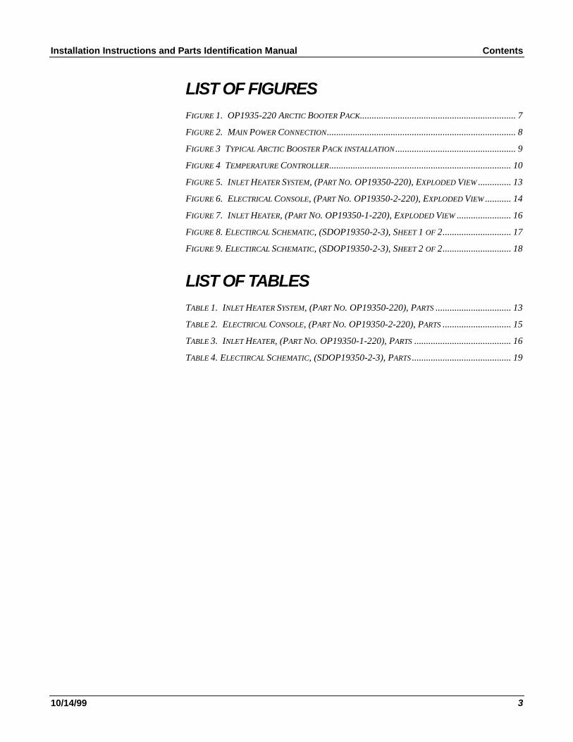
LIST OF FIGURES ..........................................................................................................3
LIST OF TABLES............................................................................................................3
WARRANTY ....................................................................................................................4
GENERAL SAFETY INFORMATION..........................................................................5
ACCEPTABLEEQUIPMENTUSES.......................................................................................5
OPERATIONAL SAFETY PROCEDURES...............................................................................6
DESCRIPTION OF CONTROLS...................................................................................7
INITIAL MACHINE SET-UP.........................................................................................8
MOUNTING OF THECONSOLE...........................................................................................8
WIRING OF THECONSOLE................................................................................................8
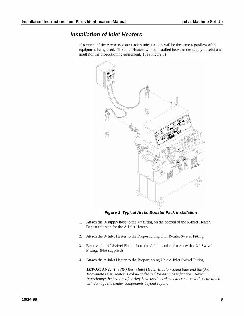
INSTALLATION OF INLET HEATERS...................................................................................9
OPERATION ..................................................................................................................10
INITIAL START-UP..........................................................................................................10
TEMPERATURECONTROLLERS.......................................................................................10
TROUBLESHOOTING .................................................................................................11
Solutions ...................................................................................................................11
PARTS IDENTIFCATION............................................................................................13
INLET HEATERSYSTEM.................................................................................................13
ELECTRICAL CONSOLE...................................................................................................14
INLET HEATER...............................................................................................................16
ELECTRICAL SCHEMATICS ....................................................................................17
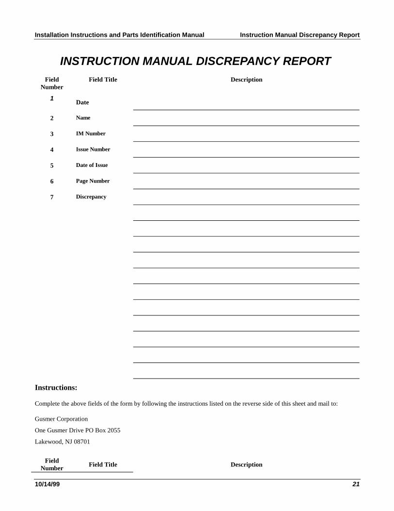
INSTRUCTION MANUAL DISCREPANCY REPORT ............................................21
Installation Instructions and Parts Identification Manual Contents
12/14/00 3
LIST OF FIGURESFIGURE1. OP19350-220 ARCTICBOOTERPACK..............................................................7
FIGURE2. MAIN POWERCONNECTION...............................................................................8
FIGURE3 TYPICALARCTICBOOSTERPACK INSTALLATION..................................................9
FIGURE4 TEMPERATURECONTROLLER...........................................................................10
FIGURE5. INLETHEATERSYSTEM, (PARTNO. OP19350-220), EXPLODEDVIEW.............13
FIGURE6. ELECTRICALCONSOLE, (PARTNO. OP19350-2-220), EXPLODEDVIEW..........14
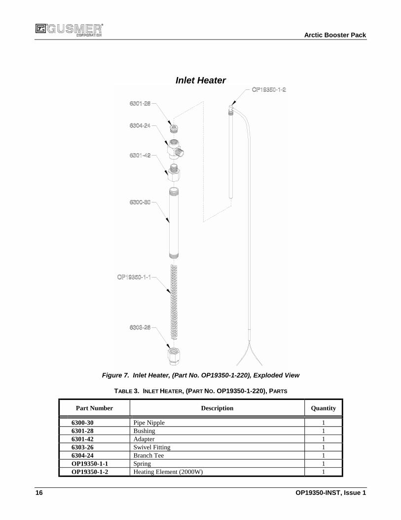
FIGURE7. INLETHEATER, (PARTNO. OP19350-1-220), EXPLODEDVIEW......................16
FIGURE8. ELECTRICALSCHEMATIC, (SDOP19350-220), SHEET1 OF 2..........................17
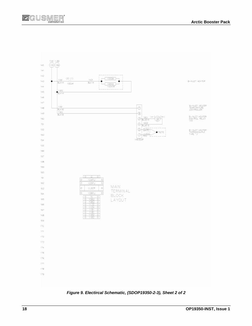
FIGURE9. ELECTRICALSCHEMATIC, (SDOP19350-220), SHEET2 OF 2..........................18
LIST OF TABLESTABLE1. INLETHEATERSYSTEM, (PARTNO. OP19350-220), PARTS...............................13
TABLE2. ELECTRICALCONSOLE, (PARTNO. OP19350-2-220), PARTS............................15
TABLE3. INLETHEATER, (PARTNO. OP19350-1-220), PARTS........................................16
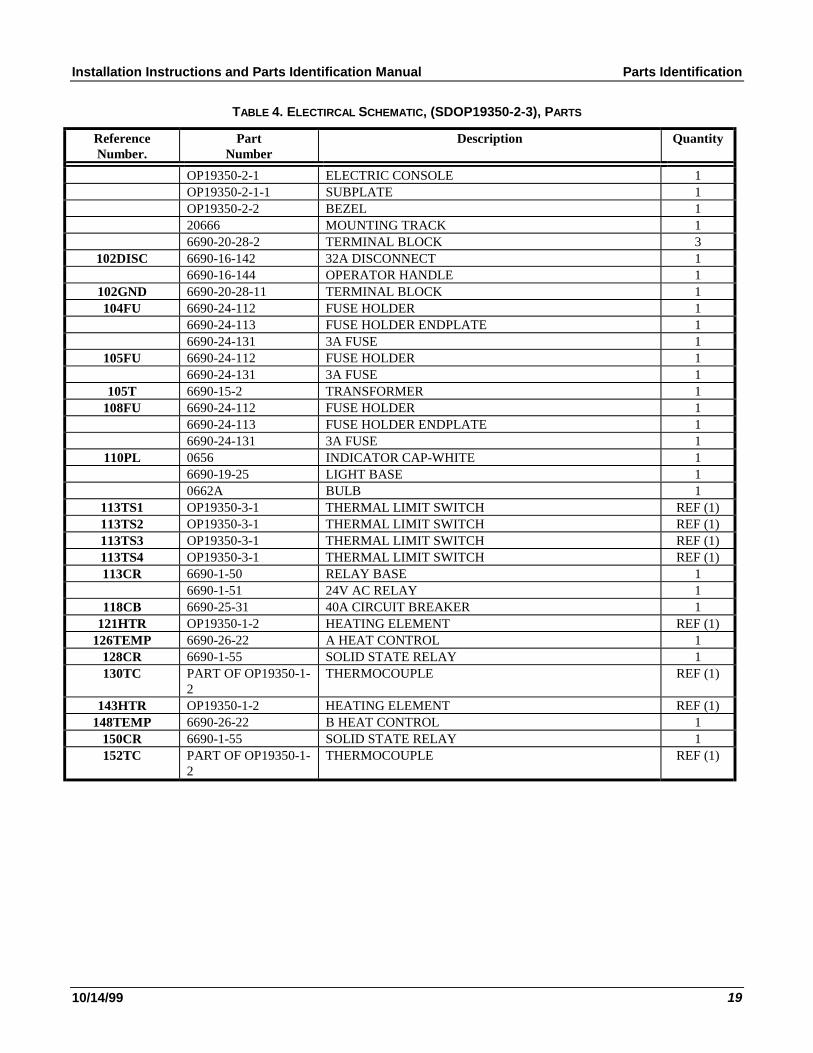
TABLE4. ELECTRICALSCHEMATIC, (SDOP19350-220), PARTS.......................................19

Arctic Booster Pack
4 OP19350-INST, Issue 3
WARRANTY
Gusmer Corporation (Gusmer) provides a limited warranty to the original purchaser (Customer) ofGusmer manufactured parts and equipment (Product) against any defects in material orworkmanship for a period of one year from the date of shipment from Gusmer facilities.
In the event Product is suspected to be defective in material or workmanship, it must be returned toGusmer, freight prepaid. If Product is found to be defective in material or workmanship, asdetermined solely by Gusmer, Gusmer will issue full credit to Customer for the freight chargesincurred in returning the defective Product, and either credit will be issued for the replacement costof the Product or a replacement part will be forwarded no-charge, freight prepaid to Customer.
This warranty shall not apply to Product Gusmer finds to be defective resulting from: installation,use, maintenance, or procedures not accomplished in accordance with our instructions; normalwear; accident; negligence; alterations not authorized in writing by Gusmer; use of “look alike”parts not manufactured or supplied by Gusmer; or Product used in conjunction with any othermanufacturer's pumping or proportioning equipment. Further, the terms and conditions of thiswarranty shall not apply to services or repairs made to Product by any third party not authorized inwriting by Gusmer. For such Product, a written estimate will be submitted to Customer at anominal service charge, itemizing the cost for repair. Disposition of Product will be done inaccordance with the terms stated on the written estimate.
The warranty provisions applied to product that are not manufactured by Gusmer will be solely inaccordance with the warranty provided by the original manufacturer of the product.
GUSMER MAKES NO WARRANTY WHATSOEVER AS TO THE MERCHANTABILITY OF,OR SUITABILITY FOR, ITS PRODUCT TO PERFORM ANY PARTICULAR PURPOSE.CREDIT FOR, OR REPLACEMENT OF, PRODUCT DEFECTIVE IN MATERIAL ORWORKMANSHIP SHALL CONSTITUTE COMPLETE FULFILLMENT OF GUSMEROBLIGATIONS TO CUSTOMER. NO OTHER WARRANTY, EXPRESS OR IMPLIED ONANY PRODUCT IT MANUFACTURES AND/OR SELLS, WILL BE RECOGNIZED BYGUSMER UNLESS SAID WARRANTY IS IN WRITING AND APPROVED BY AN OFFICEROF GUSMER.
Under no circumstances shall Gusmer be liable for loss of prospective or speculative profits, orspecial, indirect, incidental or consequential damages. Further, Gusmer shall have no liability forany expenses including, but not limited to personal injury or property damage resulting from failureof performance of the product, use of the product, or application of the material dispensed throughthe product. Any information provided by Gusmer that is based on data received from a thirdsource, or that pertains to product not manufactured by Gusmer, while believed to be accurate andreliable, is presented without guarantee, warranty, or responsibility of any kind, expressed orimplied.
Gusmer through the sale, lease, or rental of Product in no way expresses or implies a license for theuse of, nor encourages the infringement of any patents or licenses.
To insure proper validation of your warranty, please complete the warranty card and return it toGusmer within two weeks of receipt of equipment.
Revised 11/12/98

Installation Instructions and Parts Identification Manual General Safety Information
12/14/00 5
GENERAL SAFETY INFORMATIONIt is necessary to understand and follow the instructions in this manual to insure properand safe operation of the equipment.
As with most mechanical equipment, certain safety precautions must be taken when theequipment discussed in this manual is operated or serviced. Severe bodily injury ordamage to equipment and property may result if the instructions and precautions listedthroughout this manual are not followed.
Needless to say, sufficient guidelines cannot be developed to eliminate the need for goodcommon sense in the use and servicing of this equipment, and in the use and applicationof the products, this equipment has been designed to process. Users of this equipmentmust therefore, make their own determination as to the suitability of the informationcontained in this manual to their specific operation and requirements. There should be noassumption made that the safety measures and instructions contained herein are all-inclusive, and that other safety measures may not be required for specific use orapplication.
The following safety guidelines are generally applicable to the safe and efficient use ofthe equipment.
Acceptable Equipment Uses
The equipment is designed for heating two-component coating systems, and some two-component epoxy systems, specifically polyureas. Under no circumstances should anyacid or corrosive chemicals be used in the unit. Consult GUSMER if there is any doubtabout the compatibility of the chemical system to be used in this equipment.
Any use of this equipment other than as indicated above constitutes misuse unless expresswritten approval is obtained from GUSMER.
Arctic Booster Pack
6 OP19350-INST, Issue 3
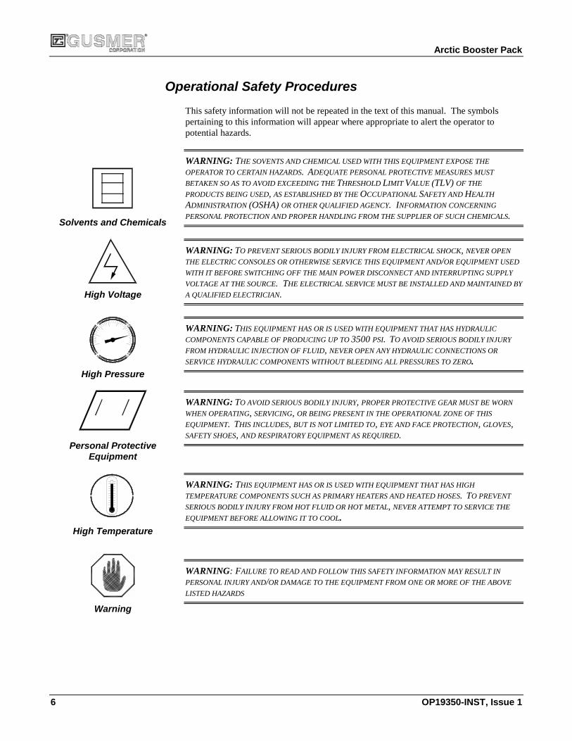
Operational Safety Procedures
This safety information is not be repeated in the text of this manual. The symbolspertaining to this information appear where appropriate to alert the operator to potentialhazards.
Solvents and Chemicals
WARNING: THE SOVENTS AND CHEMICAL USED WITH THIS EQUIPMENT EXPOSE THE
OPERATOR TO CERTAIN HAZARDS. ADEQUATE PERSONAL PROTECTIVE MEASURES MUST
BETAKEN SO AS TO AVOID EXCEEDING THETHRESHOLDLIMIT VALUE(TLV) OF THE
PRODUCTS BEING USED, AS ESTABLISHED BY THEOCCUPATIONALSAFETY ANDHEALTH
ADMINISTRATION(OSHA)OR OTHER QUALIFIED AGENCY. INFORMATION CONCERNING
PERSONAL PROTECTION AND PROPER HANDLING FROM THE SUPPLIER OF SUCH CHEMICALS.
High Voltage
WARNING: TO PREVENT SERIOUS BODILY INJURY FROM ELECTRICAL SHOCK, NEVER OPEN
THE ELECTRIC CONSOLES OR OTHERWISE SERVICE THIS EQUIPMENT AND/OR EQUIPMENT USED
WITH IT BEFORE SWITCHING OFF THE MAIN POWER DISCONNECT AND INTERRUPTING SUPPLY
VOLTAGE AT THE SOURCE. THE ELECTRICAL SERVICE MUST BE INSTALLED AND MAINTAINED BY
A QUALIFIED ELECTRICIAN.
High Pressure
WARNING: THIS EQUIPMENT HAS OR IS USED WITH EQUIPMENT THAT HAS HYDRAULIC
COMPONENTS CAPABLE OF PRODUCING UP TO3500PSI. TO AVOID SERIOUS BODILY INJURY
FROM HYDRAULIC INJECTION OF FLUID, NEVER OPEN ANY HYDRAULIC CONNECTIONS OR
SERVICE HYDRAULIC COMPONENTS WITHOUT BLEEDING ALL PRESSURES TO ZERO.
Personal ProtectiveEquipment
WARNING: TO AVOID SERIOUS BODILY INJURY, PROPER PROTECTIVE GEAR MUST BE WORN
WHEN OPERATING, SERVICING, OR BEING PRESENT IN THE OPERATIONAL ZONE OF THIS
EQUIPMENT. THIS INCLUDES, BUT IS NOT LIMITED TO, EYE AND FACE PROTECTION, GLOVES,SAFETY SHOES, AND RESPIRATORY EQUIPMENT AS REQUIRED.
High Temperature
WARNING: THIS EQUIPMENT HAS OR IS USED WITH EQUIPMENT THAT HAS HIGH
TEMPERATURE COMPONENTS SUCH AS PRIMARY HEATERS AND HEATED HOSES. TO PREVENT
SERIOUS BODILY INJURY FROM HOT FLUID OR HOT METAL, NEVER ATTEMPT TO SERVICE THE
EQUIPMENT BEFORE ALLOWING IT TO COOL.
Warning
WARNING: FAILURE TO READ AND FOLLOW THIS SAFETY INFORMATION MAY RESULT IN
PERSONAL INJURY AND/OR DAMAGE TO THE EQUIPMENT FROM ONE OR MORE OF THE ABOVE
LISTED HAZARDS

Installation Instructions and Parts Identification Manual Description of Controls
12/14/00 7
DESCRIPTION OF CONTROLS
��������
MODEL 15-20220V 20ASINGLE PHASE 60 CYCLE
������B���P
A ����
���� ���
Figure 1. OP19350-220 Arctic Booter Pack
1. POWER DISCONNECT- Controls power to all circuits; must be ON for anyfunction of the unit to operate.
�� A White pilot light indicates the Power Disconnect is ON.
2. HEATER CONTROL BREAKER- Controls power to A- and R-Inlet Heater. Itmust be ON for the unit to operate.
3. A-INLET HEATER TEMPERATURE CONTROLLER- Controls thetemperature of the A-Inlet Heater. Adjust the setpoint to the desired temperature.From this point, the temperature control is automatic.
4. R-INLET HEATER TEMPERATURE CONTROLLER- Controls thetemperature of the R-Inlet Heater. Adjust the setpoint to the desired temperature.From this point, the temperature control is automatic.