Archkological Salvage Excavation GhGk-4 1990 · Structure 3 Outline Page 2 12 . iii ... training in...
53
Archkological Salvage Excavation of the GhGk-4 site, 1990 Presented to: Whapmagoostui Band Council and Municipality of Kuujjuarapik By: Avataq Cultural Institute November, 1992
Transcript of Archkological Salvage Excavation GhGk-4 1990 · Structure 3 Outline Page 2 12 . iii ... training in...
Archkological Salvage Excavation
of the GhGk-4 site, 1990
Presented to:
Whapmagoostui Band Council
and
Municipality of Kuujjuarapik
By:
Avataq Cultural Institute
November, 1992
3 Appendices
1 Acknowledgments
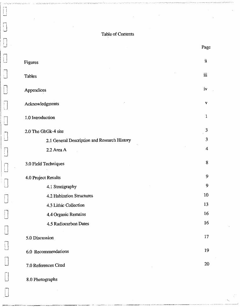
Table of Contents
Page
1 1.0 Introduction
1 -3 2.0 The GhGk-4 site
/ 2.1 General Description and Research History
2.2 Area A
3.0 Field Techniques
4.0 Project Results
4.1 Stratigraphy
4.2 Habitation Structures
4.3 Lithic Collection
4.4 Organic Remains
4.5 Radiocarbon Dates
5.0 Discussion
6.0 Recommendations
7.0 References Cited
8.0 Photographs
Figures
Figure 1. Location of the GhGk-4 site
Figure 2. Structure 3 Outline
Page
2
12
iii
Tables
Page
Table 1. Summary of Cultural Features Identified in Area A of the GhGk-4 site
I Table 2. Summary of the Lithic Collection ' '-1
-J
Table 3. Lithic Categories and Raw Materials
d Table 4. List of Charcoal and Carbonized Grease Samples.

Appendices
17 Appendix 1. List of Photographs d
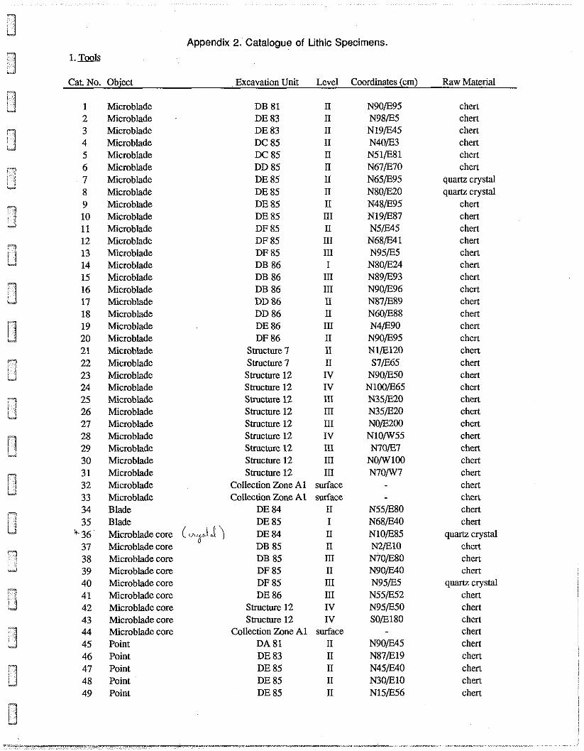
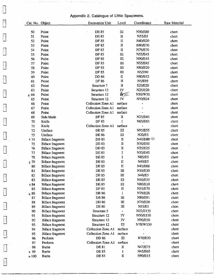
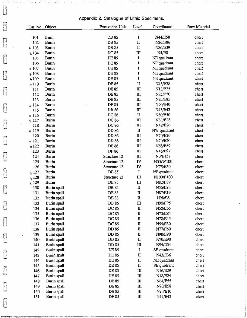
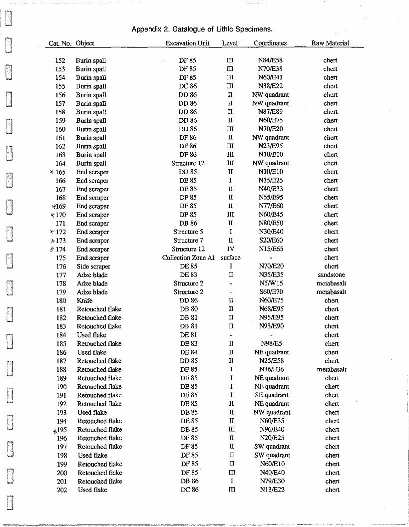
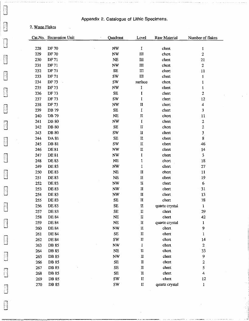
1 Appendix 2. Catalogue of Lithic Specimens i
I n Appendix 3. Plan of Area A
1 Appendix 4. Plans and Profiles of Structures 1 and 2
I Appendix 5. Plans and Profiles of Structures 4,5 and 7
7 ,i Appendix 6. Plans and Profiles of Structures 12 and 17
"I
Acknowledgments
'1
-1 We wish to express our appreciation to Chief Robbie Dick of the Whapmagoostui Cree Band . I and Sappa Fleming, past mayor of the Municipality of Kuujjuarapik, for their co-operation in
& 1 arranging the salvage excavation project at the GhGk-4 site. Our thanks as well to Elizabeth Dick of
Whapmagoostui and Lucassie Cookie, Manager of the Sakkuq Landholding Corporation of
Kuujjuarapik, who acted as local project managers on the behalf of their respective communities.
" 1 -J
Also, special thanks to David Mastie, Jr., of the Whapmagoostui Band Council, and to the Council
itself for providing the field crew a truck for daily transportation between the village and the site. "7
I The project was supported by a grant from the ministhe des Affaires culturelles du Quibec to J the Cree Regional Authority and by funds apportioned from that minisay's allocations to Avataq for
:1 archaeology.
The Avataq Cultural Institute and the Cree Regional Authority gratefully acknowledge the - contributions fo the above individuals and agencies to the GhGk-4 archaeological salvage excavation
.J project.
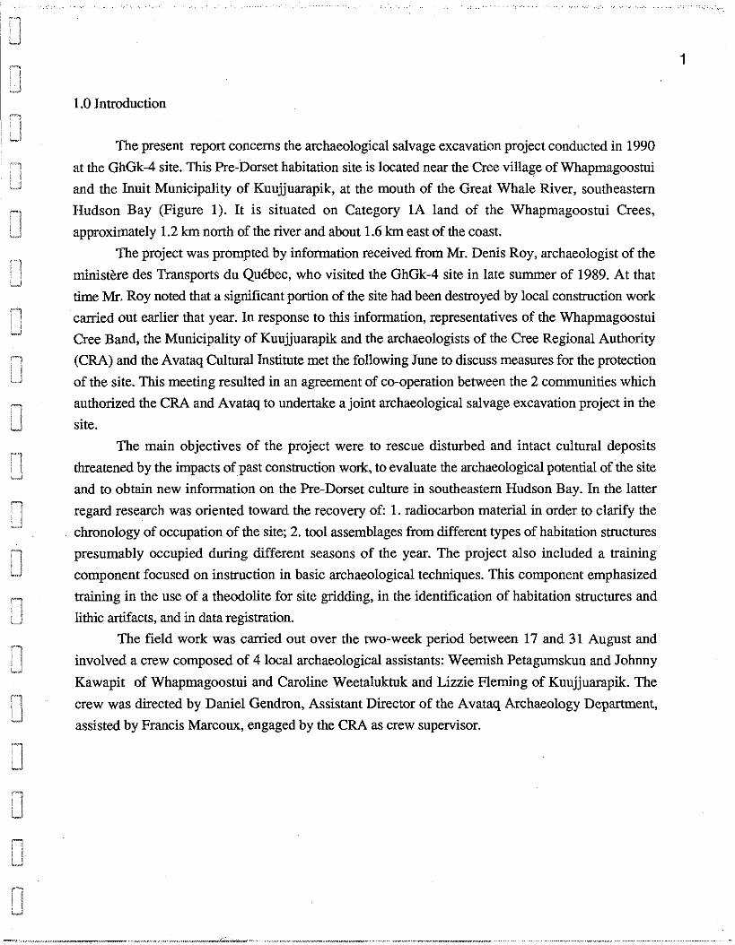
1.0 Introduction
The present report concerns the archaeological salvage excavation project conducted in 1990
at the GhGk-4 site. This Re-Dorset habitation site is located near the Cree village of Whapmagoostui
and the Inuit Municipality of Kuujjuarapik, at the mouth of the Great Whale River, southeastern
Hudson Bay (Figure 1). It is situated on Category 1A land of the Whapmagoostui Crees,
approxi~nately 1.2 km north of the river and about 1.6 km east of the coast.
The project was prompted by information received from Mr. Denis Roy, archaeologist of the
ministkre des Transports du Qukbec, who visited the GhGk-4 site in late summer of 1989. At that
time Mr. Roy noted that a significant portion of the site had been destroyed by local construction work
canied out earlier that year. In response to this information, representatives of the Whapmagoostui
Cree Band, the Municipality of Kuujjuarapik and the archaeologists of the Cree Regional Authority
(CRA) and the Avataq Cultural Institute met the following June to discuss measures for the protection
of the site. This meeting resulted in an agreement of co-operation between the 2 communities which
authorized the CRA and Avataq to undertake a joint archaeological salvage excavation project in the
site.
The main objectives of the project were to rescue disturbed and intact cultural deposits
threatened by the impacts of past construction work, to evaluate the archaeological potential of the site
and to obtain new information on the Re-Dorset culture in southeastern Hudson Bay. In the latter
regard research was oriented toward the recovery of: 1. radiocarbon material in order to clarify the
chronology of occupation of the site; 2. tool assemblages from different types of habitation structures
presumably occupied during different seasons of the year. The project also included a training
component focused on instruction in basic archaeological techniques. This component emphasized
training in the use of a theodolite for site gridding, in the identification of habitation smctures and
lithic artifacts, and in data registration.
The field work was carried out over the two-week period between 17 and 31 August and
involved a crew composed of 4 local archaeological assistants: Weemish Petagumskun and Johnny
Kawapit of Whapmagoostui and Caroline Weetaluktuk and Lizzie Fleming of Kuujjuarapik. The
crew was directed by Daniel Gendron, Assistant Director of the Avataq Archaeology Department,
assisted by Francis Marcoux, engaged by the CRA as crew supervisor.

Figure 1. Location of the GhGk-4 Site
2.0 The GhGk-4 site
2.1 General Description and Research History
The GhGk-4 site occupies an extensive boulder field situated at a relatively high altitude. It
consists of a series of boulder beach ridges formed by ice-push action during the post-glacial Tyrrell
Marine Transgression. The formation measures 130 x 260 m in maximum dimensions and is
interrupted by a flat bedrock outcrop covering roughly 5,600 m2. The boulder field is bounded to the
east and west by bedrock hills and, to the north and south, by outcrops and lower, wet zones. Stands
of black spruce mixed with shrubs occur in the lower zones.
The GhGk-4 site was discovered by members of a research team from the Centre d'itudes
Nordiques, Universiti Laval, who, canying out ecological studies in the area in 1968, noted curious
depressions in the boulder field. Informed of these depressions, Patrick Plumet travelled to the
locality in 1969 and recorded 17 habitation structures and 7 exterior features in the western section of
the formation (c.f., Plumet, 1976, Figure 4). Plumet's excavation of one of the sauctures and testing
of another yielded 263 lithic artifacts. Projectile points and burins included in the collection indicated
that the site had been occupied by groups of the Pre-Dorset culture. A radiocarbon assay of 3,300 f
100 B.P. (GIF 1576)* obtained on wood charcoal from the excavated structure was later corrected to
3,671 B.P., or 1721 B.C. (Plumet, 1976: 142-144).
In 1970 Elmer Harp, Jr., of Dartmouth College, New Hampshire, and his crew excavated 3
habitation structures and tested a fourth in the site. Harp's unpublished field notes provide the only
description of these excavations. The 608 lithic artifacts recovered from this work, along with those
collected earlier, were subsequently analyzed by Plumet (1980).
In 1988 the ministkre des Transports du Quibec mandated the Cree Regional Authority to
carry out an archaeological potential study and pre-inventory of the Kuujjuarapik airport study area.
The pre-inventory, conducted in collaboration with the Avataq Cultural Institute, included a visual
inspection of GhGk-4. This inspection resulted in the identification of more than 50 habitation
structures and in the redefinition of the site as covering the entire boulder field (Denton and Laforte,
n.d.). Disturbance noted at that time consisted of a shallowly-graded ATV trail crossing the
southwestern part of the site. The south-central section of the site was destroyed the following year by
the extraction of boulders for local construction work.
*B.P. refers to "Before the Present", which is fixed in archaeology at A.D. 1950. The capital letters
and number in brackets following the B.P. date identify the radiocarbon laboratory and number of the
processed sample.
Disturbance caused by boulder extraction work and the ATV trail covers 2,000 m2 (c.f.,
Appendix 3). This disturbance includes 2 deep borrow pits, one of which is located on the southern
edge of the central outcrop and the other on the extreme southeastern limit of the area. A shallower
extraction zone and access road, both of which have been bulldozed to the bedrock surface, and piles
of redeposited overburden are situated in the intervening space. Redeposited overburden and a
scraped zone extend along the western, southern and eastern peripheries of the southeastern borrow
pit.
2.2 Area' A.
The natural configuration of the boulder field and the disturbed portion of the site allow
GhGk-4 to be divided into 3 "areas". Area A comprises the western section of the boulder field while
Areas B and C encompass the southeastern and northeastern parts of the formation. All salvage
activities were carried out in Area A. Area A corresponds, in general, to the site as originally defined in 1969. It is bordered to the
west by a bedrock hill and, to the east, by the central outcrop. The southeastern limit is formed by the
disturbed zones.The area varies in altitude from 63 to 70 m.a.s.1. and covers approximatly 9,500 m2,
with maximum dimensions of 105 x 120 m. The greater part of the surface boulders average from 30
to 50 cm in overall dimensions, increasing to more than 1 metre in the southwestern part of the area.
Vegetation is composed of some stunted black spruce, isolated shrubs and a few patches of mosses
and lichens intermixed with grass.
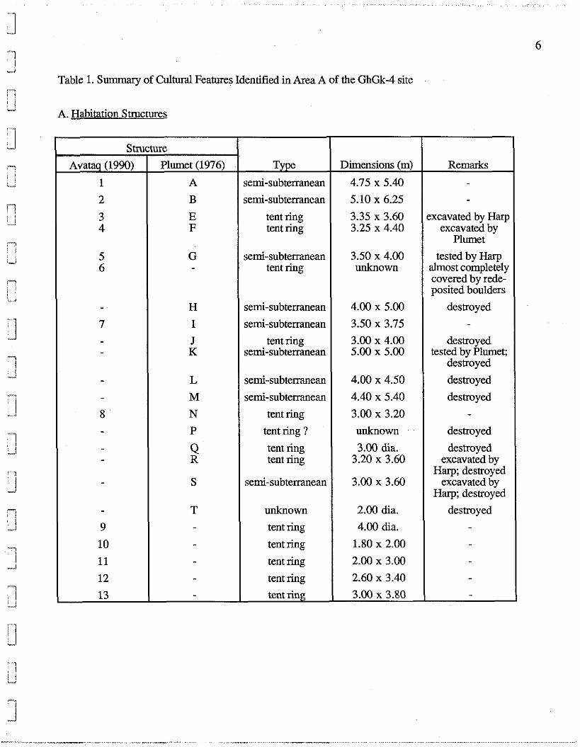
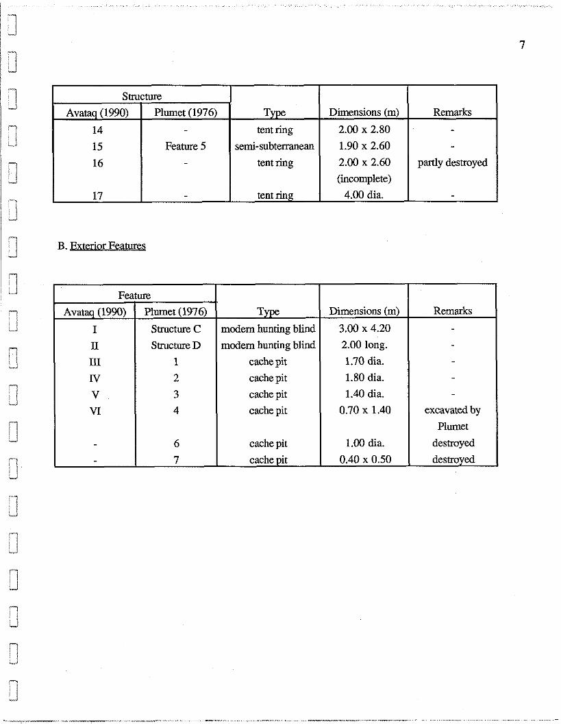
Seventeen habitation structures and 6 exterior features are presently indentified in the area
(Table 1). These remains include 7 habitations which, recorded in 1969, have been renumbered in
order to avoid confusion. Ten other structures and 2 features registered that year have been
obliterated by extraction work. The type and dimensions of the destroyed components presented in
Table 1 are as listed in Plumet (1976 : 77-92).
Extant habitation structures are represented by 5 semi-subterranean dwellings and 12 tent
rings. The semi-subterranean dwellings are characterized by oval depressions of variable depth
surrounded either wholly or in part by raised rims. The smallest, interpreted in 1969 as a cache pit,
measures 1.90 x 2.60 m and the largest, 5.10 x 6.25 m. Two of the tent rings are circular and 9 are
oval in shape. The latter vary from 1.80 x 2.00 m to 3.25 x 4.40 m in dimensions. Each of the
circular tent rings is 4.00 m in diarnetre. Another tent ring (i.e., Structure 6) is suggested by a semi-
circular alignment of rocks projecting from beneath a pile of redeposited boulders. The form and
dimensions of this habitation are unknown.
1 The exterior features comprise 2 modem hunting blinds and 4 cache pits. One of the blinds -
consists of a rock-built wall, 1.10 m in interior height, enclosing an oval space carpetted with spruce
boughs. The second is composed of a semi-circular rock wall, about 0.50 m in height. The situation I of the cache pits close to 2 habitation structures suggests an Early Palaeoeskimo origin for these
1 features. All habitation structures in Area A are considered to be Pre-Dorset in cultural afhliation.
6 !"I
I d
Table 1. Summary of Cultural Features Identified in Area A of the GhGk-4 site
3 A. Habitation Structures
I ~ . . 3 J -1
\
3 g 3 [i
3
1 7 cl
7 ,J
rl ! 1 h
"i i..,
'1 L"d
7 L J
-7 - I
"
Dimensions (m)
4.75 x 5.40
5.10 x 6.25
3.35 x 3.60 3.25 x 4.40
3.50 x 4.00 unknown
4.00 x 5.00
3.50 x 3.75
3.00 x 4.00 5.00 x 5.00
4.00 x 4.50
4.40 x 5.40
3.00 x 3.20
unknown
3.00 dia. 3.20 x 3.60
3.00 x 3.60
2.00 dia.
4.00 dia.
1.80 x 2.00
2.00 x 3.00
2.60 x 3.40
3.00 x 3.80
Type semi-subterranean
semi-subterranean
tent ring tent ring
semi-subterranean tent ring
semi-subterranean
semi-subterranean
tent ring semi-subterranean
semi-subterranean
semi-subterranean
tent ring
tent ring ?
tent ring tent ring
semi-subterranean
unknown
tent ring
tent ring
tent ring
tent ring
tent ring
Structure
Avataq (1990)
1
2
3 4
5 6
-
7 - -
- - 8 - - -
-
-
9
10
11
12
13
Remarks - -
excavated by Harp excavated by
Plumet
tested by Harp almost completely covered by rede- posited boulders
destroyed -
destroyed tested by Plumet;
destroyed
destroyed
destroyed -
destroyed
destroyed excavated by
Harp; destroyed excavated by
Harp; destroyed
destroyed - - - - -
Plumet (1976)
A
B
E F
G -
H
I
J K
L
M
N P
Q R
S
T - - - - -
1 B. Exterior Features
Structure
Avataq (1990)
14
15
16
17
Remarks - -
partly destroyed
-
Type tent ring
semi-subterranean
tent ring
tent ring
Plumet (1976) -
Feature 5 -
-
Remarks - - - - -
excavated by
Plumet
destroyed
destroyed
Dimensions (m)
2.00 x 2.80
1.90 x 2.60
2.00 x 2.60
(incomplete)
4.00 dia.
Feature *.
Type modem hunting blind
modem hunting blind
cache pit
cache pit
cache pit
cache pit
cache pit
cache pit
Avataq (1990)
I
I1
III
IV V VI
- -
Dimensions (m)
3.00 x 4.20
2.00 long.
1.70 dia.
1.80 dia.
1.40 dia.
0.70 x 1.40
1.00 dia.
0.40 x 0.50
Plumet (1976)
Structure C
Structure D
1
2
3 4
6
7
3.0 Field Techniques.
Area A was mapped and gridded using a Sokkisha theodolite and 60-metre surveyors' chain.
The grid was composed of intersecting l-metre bands extending from a reference point arbitrarily
placed well to the southwest of the area. North-south bands were numbered while those oriented east-
west were assigned alphabetical letters. The resulting square metres were alpha-numerically coded
(i.e., DA 88), with the value of the numbers and letters increasing toward the north and east,
respectively.
The square metres formed the basic units for testing and the excavation of 1 tent ring. Waste
flakes produced by lithic tool manufacturing recovered in these units were collectively registered
according to quadrant and stratigraphic level. The quadrants, measuring 50 x 50 cm, were identified
by their position in a square metre (i.e., southeast, northwest, etc.). The north and east co-ordinates
of each tool and tool fragment were recorded and these specimens were individually collected.
Other habitation stuctures were excavated by "habitation" quadrants. This procedure involves
the subdivision of a structure into 4 equal parts based on the orientation of its length axis. Techniques
used to register lithic artifacts in the square metres were applied to habitation quadrants. However, in
these cases tools were recorded in relation to quadrant dividing lines which, the quadrant depending,
may assume a number of different cardinal orientations.
Surface-collecting was carried out in a part of the scraped area immediately east of the
southeastern borrow pit (i.e., Collection Zone 1A ) and, to a limited extent, on the access road. Only
the general provenience of the surface-collected lithics was registered
The location of all excavated artifacts and other occupational remains was plotted on
millimemc graph paper at a scale of 1:10. Plans of the excavated habitation structures, the test
excavations and stratigraphic profiles were also drawn at this scale. Area A in general, the structures,
excavations and other details were photographed in colour and black and white prints and slides.
4.0 Project Results.
Approximately 105 m2 were excavated. These excavations were centred primarily on
Structures 1, 2, 5,7, 12 and 17. Structures 3 and 4, the interiors of which were excavated by Harp
and Plumet, respectively, were also tested. Features III, IV and V, 3 cache pits, were excavated, with
negative results. Excavations extended where possible to the limit of artifact infiltration, defined by
sterile sand-gravel or bedrock. Work in Structures 1 and 2 was arrested at a depth of 1 m by massive
boulders.
4.1 Stratigraphy.
The profiles observed in Structures 1 and 2 are composed of unsorted boulders of variable
dimensions interspersed with smaller stones. An unsorted boulder deposit, ranging from 30 to 80 cm
in thickness, also occurs in Structure 5 (Appendix 5). This deposit overlies a layer of pebbles which,
varying from 5 to 50 cm in thickness, is underlain by gravel impregnated with decayed vegetal matter.
The upper stratigraphic unit in Structure 7 consists of a layer of boulders, attaining a maximum
thickness of 1.50 m in the rim of the habitation. The boulders generally decrease in size with
increased depth and overly a horizon of coarse gravel high in organic content. The gravel horizon in
the southern and central sections of the structure is roughly 20 cm thick and rests on bedrock. The
surface of the bedrock dips abruptly to an unknown depth in the northern and western parts of the
dwelling.
The upper units in Structures 5 (including the pebble layer) and 7 were recorded as Level I and
the underlying gravel horizons in both habitations as Level II.
Structures 12 and 17 are situated in shallow, natural depressions which, acting as catchment
basins, have promoted vegetation growth and the development of organic soil. The stratigraphic
levels revealed in Structure 12 are summarized as follow:
Level I - ~ ~ S C O ~ M O U S vegetation mat composed mainly of mosses and lichens,
averaging 6 cm in thickness.
Level II -sandy humus layer, 5 to 10 cm in thickness.
Level III -boulder layer, 20 to 30 cm in thickness.
Level IV -gravel horizon, 25 cm in thickness.
The stump of a small black spruce occurs in the centre of the suucture. The roots of this tree
extend throughout Levels I and I1 in the central portion of the habitation.
Levels I and I1 in Structure 17 are of similar composition and thickness. However, in this
instance the boulder layer is replaced by scattered boulders, with Level I1 humus directly overlying a
sand-gravel horizon. This horizon, designated Level I11 in Structure 17, varies from 10 to 25 cm in
thickness and, as in Structure 12, is underlain by large boulders.
A comparable stratigraphic sequence was observed in the test pits excavated on the peripheries
of Structures 3 and 4. The vegetation and humus layers were absent in the interiors of these
structures, the earlier excavation of which penetrated into the Level Ill gravel.
4.2 Habitation Structures
Semi-subterranean Dwellings.
Structures 1 and 2 are built into adjacent north-facing boulder ridges (Appendix 4). These oval
dwellings are east-west in orientation and surrounded by generally pronounced rims. The northern
portions of the rims of both structures are poorly defined.
The exterior dimensions of Structure 1, measured from the crest of the rim, are 4.75 x 5.40 m.
Interior rim slopes are of varying gradient and length, enclosing a relatively flat space measuring 2.85
x 3.30 m and 50 cm in average depth. A slight depression roughly 85 cm in diametre occupies the
centre of the dwelling. A circular arrangement of rocks, 55 cm in diametre, located in the southeastern
quadrant is interpreted as a cache. An east-west alignment of boulders crossing the interior space
suggests the edge of a sleeping platform. The alignment is bordered to the north by two, contiguous
circles of rocks possibly representing hearths. Each circle is about 50 cm in diametre.
Structure 2 measures 5.10 x 6.25 m in exterior dimensions and 2.40 x 3.75 m in interior
dimensions. Its depth varies from 45 to 65 cm. A cache composed of an irregularly-shaped
arrangement of rocks roughly 70 cm in overall dimensions is situated in the northwest quadrant.
Interior features of unknown function are suggested by a concentration of boulders in the western part
of the same quadrant and by a rock alignment in the northeastern quadrant.
Structure 5 was classified in 1969 as a tent ring (Plumet, 1976: 72) and recorded the following
year by Harp (n.d.: 3) as being rectangular in shape. However, as illustrated by the profile presented
in Appendix 5, this structure is clearly semi-subterranean in nature, attaining a depth of 30 cm. As
well, its complete excavation in 1990 revealed an oval contour for the dwelling, with exterior
dimensions of 3.50 x 4.00 m. The length axis is oriented east-west. Harp's sampling of the structure
is represented by a 50 x 65 cm test pit in the southeast quadrant.
Structure 7 is oval in form, measures 3.50 x 3.75 m and is oriented north-south. Its depth
increases from 15 cm along the interior edge to 50 cm in the centre of structure. As in the case of
Structure 5, a number of flagstones are scattered throughout the habitation. No interior features were
identified in either dwelling.
Tent Rines
Structure 12 consists of an oval configuration of irregularly-spaced boulders (Appendix 6). It
measures 2.00 x 3.00 m and is east-west in orientation. A rock concentration associated with pockets
of charcoal near the intersection of the 3 excavated quadrants indicates a central hearth area
The excavation of the northern and south-central portions of Structure 17 suggests a circular
tent ring, about 4.00 m in diametre. The structure is bisected by a mid-passage composed of 2 parallel
rows of rocks oriented northwest-southeast. This feature, initially obscured by surface vegetation, is
60 to 70 cm wide. Although some of its constituent rocks rest on Level Ill gravel, the mid-passage
appears to be associated with the Level I1 humus. A deposit of carbonized grease was situated in the
northwestern extremity of the mid-passage and pockets of charcoal were located in the northern part
of the habitation. Numerous small fragments of charcoal were scattered to the west of the structure.
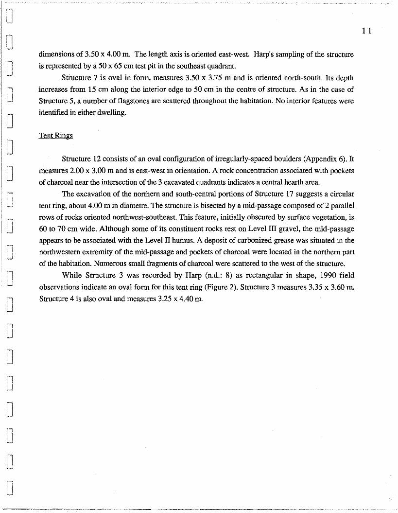
While Structure 3 was recorded by Harp (n.d.: 8) as rectangular in shape, 1990 field
observations indicate an oval form for this tent ring (Figure 2). Structure 3 measures 3.35 x 3.60 m. Structure 4 is also oval and measures 3.25 x 4.40 m.
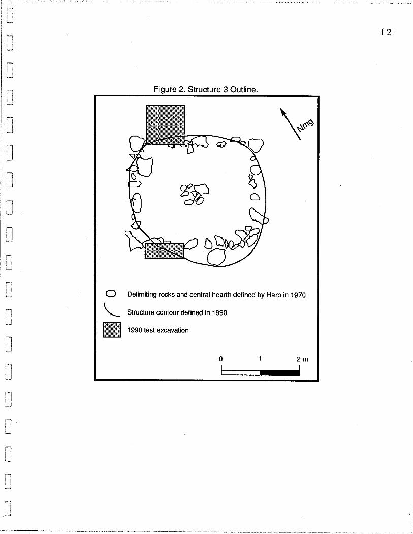
Figure 2. Structure 3 Outline. I I
I 0 Delimiting rocks and central hearth defined by Harp in 1970 1 I \ Structure mntour defined in 1990 I & : . .$ 1990 test emat ion

4.2 Lithic Collection.
The excavations and surface-collecting produced a total of 4,737 lithic artifacts, comprising
233 tools, 4,501 waste flakes and 3 unworked quartz crystals (Table 2). The bulk of the collection
was recovered from Structure 17 (72.6%), followed by Collection Zone A1 (12.3%) and Structure 12
(1 1.9%). In contrast, only 63 artifacts, or 1.5% of the collection, were retrieved from the 4 excavated
semi-subterranean dwellings. Test-pitting in Structures 3 and 4 yielded 64 lithics and 14 others were
surface-collected on the access road.
The majority of the specimens from Structures 3, 5, 7 and 12 were located in the gravel
horizon. Roughly equal amounts of lithics were associated with the humus and gravel level in
Structure 17. Artifact frequency increased around the mid-passage in this tent ring and in the hearth
area of Structure 12. No distribution patterns were evident in the other structures.
The largest portions of the tool assemblage were furnished by Structure 17 (N=170) and
Structure 12 (N=31). Nineteen implements were registered in Collection Zone A1 and the semi-
subterranean dwellings provided a total of 13 tools. The assemblage is dominated, numerically, by
burins and burin spalls, microblades, retouched flakes, projectile points and fragments of bifacially-
worked implements of unknown function. Many of the burin spalls, some of which may have been
reworked, appear to have been used as small engraving tools or perforators. The projectile points
include stemmed and triangular forms as well as micropoints. End scrapers, microblade cores and
flake cores are also relatively numerous in the assemblage while knives are comparatively rare. A
small number of used flakes, 3 chipped and polished adze blades, 2 large blades, 2 uniface fragments,
2 preforms, a side scraper, a side blade and a hammerstone complete the list of tools.
Differences in the frequency of tools recovered from the individual structures are accompanied
by notable contrasts in the number of implement categories associated with the different habitation
types. For example, all 18 categories contained in the assemblage were found in Structure 17 and 10
categories were present in Structure 12. Only 7 categories occurred in the 3 semi-subterranean
dwellings that produced tools. Five of these categories were represented in separate dwellings. Tools
common to 2 dwellings are end scrapers, occurring in Structures 5 and 7, and used flakes, occuring
in Structures 2 and 5. Most of the waste flakes in the collection are small, suggesting relationships with the final
stages of tool manufacturing. Microblade core blanks are suggested for the unworked quartz crystals.
Mottled black chert is the overwhelmingly predominant raw material, representing 99% of the
collection. Twenty artifacts are in quartz crystal, 15 are in metabasalt and 5 are in metamorphosed
sandstone. The raw material of 4 specimens is undetermined.
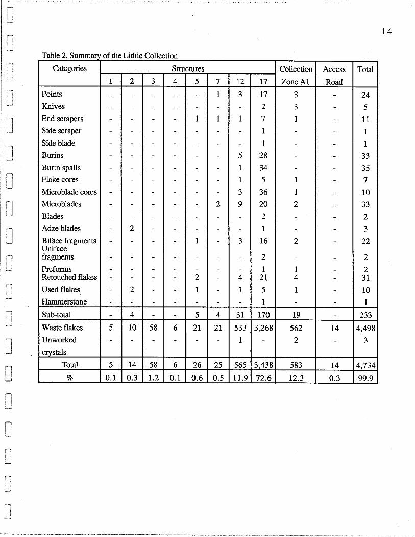
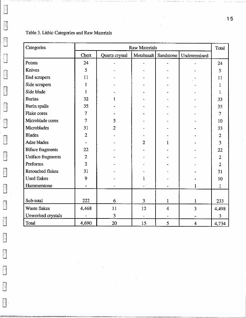
3 Table 3. Lithic Categories and Raw Materials
Categories
Points
Knives
End scrapers
Side scrapers
Side blade
Burins
Burin s p d s
Flake cores
Microblade wres
Microblades
Blades
Adze blades
Biface fragments
Uniface fragments
Preforms
Retouched flakes
Used flakes
Hammerstone
Sub-total
Waste flakes
Unworked crystals
Total
Total
24
5
11
1
1
33
35
7
10
33
2
3
22
2
2
3 1
10
1
233
4,498
3
4,734
Chert
24
5 11
1
1
32
35
7
7
3 1
2 -
22
2
2
31
9 -
222
4,468 -
4,690
Quartz crystal - - - - -
1 - -
3
2 - - - - - - - -
6
11
3
20
Raw Materials
Metabasalt - - - - - - -
- - -
2 - .
.
-
1 -
3
12 .
15
Sandstone - - - - - - - - - - -
1 - - - - - -
1
4 -
5
Undetermined - - - - - .
- - - - - -
- -
1
1
3 -
4
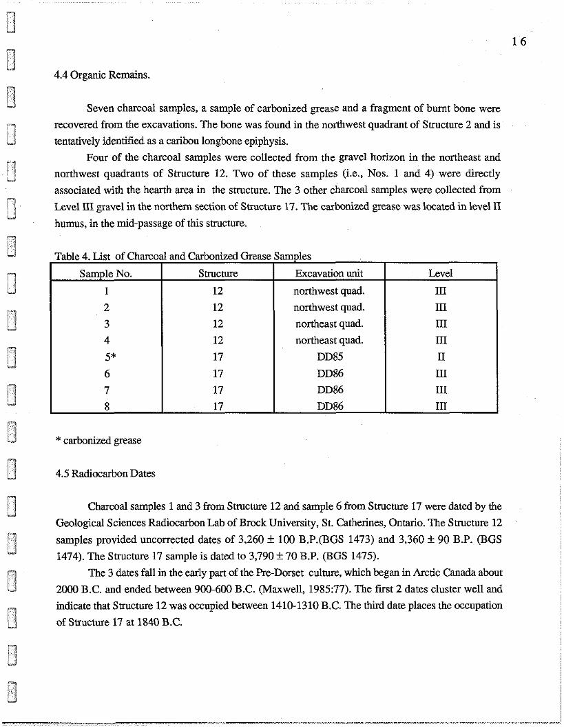
4.4 Organic Remains.
Seven charcoal samples, a sample of carbonized grease and a fragment of burnt bone were
recovered from the excavations. The bone was found in the nosthwest quadrant of Structure 2 and is
tentatively identified as a caribou longbone epiphysis.
Four of the charcoal samples were collected from the gravel horizon in the northeast and
northwest quadrants of Structure 12. Two of these samples (i.e., Nos. 1 and 4) were directly
associated with the hearth area in the structure. The 3 other charcoal samples were collected from
Level 111 gravel in the northern section of Structure 17. The carbonized grease was located in level II
humus, in the mid-passage of this structure.
Table 4. List of Charco
Sample No.
1
2
3
4
5*
6
7
* carbonized grease
1 and Carbonized Grease Samples
4.5 Radiocarbon Dates
Charcoal samples 1 and 3 from Structure 12 and sample 6 from Structure 17 were dated by the
Geological Sciences Radiocarbon Lab of Brock University, St. Catherines, Ontario. The Structure 12
samples provided uncorrected dates of 3,260 f 100 B.P.(BGS 1473) and 3,360 + 90 B.P. (BGS
1474). The Structure 17 sample is dated to 3,790 + 70 B.P. (BGS 1475).
The 3 dates fall in the early part of the Pre-Dorset culture, which began in Arctic Canada about
2000 B.C. and ended between 900-600 B.C. (Maxwell, 1985:77). The first 2 dates cluster well and
indicate that Smcture 12 was occupied between 1410-1310 B.C. The third date places the occupation
of Siructure 17 at 1840 B.C.
Level
111
111
1n
ID
11
111
111
Structure
12
12
12
12
17
17
17
Excavation unit
northwest quad.
northwest quad.
northeast quad.
northeast quad.
DD85
DD86
DD86
5.0 Discussion.
The radiocarbon determinations available for GhGk-4 including Plumet's corrected date, tend
to suggest 2 phases of occupation in Area A. The earlier phase extends from mid-1800 to 1720 B.C.
and probably represents the initial Pre-Dorset occupation of southeastern Hudson Bay. The later
phase, also approximately 100 years in length, began around 1400 B.C.
The above chronological framework might indicate Early Palaeoeskimo abandonment of
southeastern Hudson Bay during an interval of 3 centuries or a temporary shift in settlement by a
population resident in the region since the early 2nd millenium B.C. On the other hand, it is not
known whether the occupation hiatus suggested in Area A by the radiocarbon dates actually exists.
This apparent hiatus may be a function of archaeological bias, with structures dating to that interval
remaining unexcavated.
Altitudinal differences often provide some indication of differences in the ages of habitation
structures. As in the case of historic Inuit, prehistoric Inuit groups generally placed their camps close
to the contemporaneous shoreline. With decreased marine levels and the correspondent emergence of
new shorelines due to isostatic uplift through time, later habitations in a site were located at
successively lower altitudes. Initial uplift in southeastern Hudson Bay was particularly rapid and may
have been as much as 3 mlcentury during the period bracketed by the GhGk-4 radiocarbon dates (c.f.,
Hillaire-Marcel, 1979). Theoretically then, Structure 17 should be situated at a noticeably higher
elevation than Structure 12, which was occupied more than 400 years later.
However, these structures occur on the same beach ridge and are separated in altitude by less
than one metre. Obviously, the location of habitations in Area A was influenced not only by the
position of the shoreline but by a combination of factors such as protection against prevailing winds
and the variable character of the boulder field. These factors may explain the concentration of
structures in the southeastern portion of the area which, including those destroyed by construction
work, contained no less than 24 habitations.
Cold-weather occupations are indicated by the semi-subterranean dwellings and warm-weather
occupations by the tent rings. Most of the habitations are of similar size and, based on ethnographic
analogy, would have been occupied by single nuclear families averaging 4 or 5 individuals. Larger
social units consisting of 2 nuclear families or extended families are interpreted for Structures 1 and 2.
No more than 2 individuals are speculated for Structures 10 and 15.
The spatial relationships of Structures 1 and 2 and of Structures 5 and 7 suggest that the
dwellings in each of these habitation clusters were simultaneously occupied. Two winter camps
composed of 2 households and a third camp represented by Structure 15 are implied. No clear spatial
patterning is apparent among the tent rings. However, the close proximity of Structures 4, 10 and 13
to semi-subterranean dwellings may point to occupation of these structures by families that inhabited
the adjacent dwellings.
Multiple reoccupations of Structure 17 are suggested by the large number of lithics recovered
from this tent ring. Structure 12, at least one reoccupation of which is attested by the radiocarbon
dates, may also have been reoccupied on several occasions. The tools associated with these
habitations reflect a wide variety of subsistence and domestic activities. Although faunal remains are
lacking, variation in projectile point style and size suggest the hunting of sea mammals, terresmal
game and, possibly, buds. The knives, rnicroblades, blades and end scrapers are related principally to
butchering and hide processing and the burins, side scraper and adze to the fashioning of cultural
equipment in bone, antler, ivory and wood. The burin spalls may also have been used in the
production of organic implements, for hide perforation, or both. In addition, the large quantity of
waste flakes collected from the 2 tent rings indicates that lithic tool manufacturing was relatively
intensively carried out by the inhabitants of the structures.
The few tools and small amount of waste flakes recovered from the semi-subterranean
dwellings suggest a more limited range and reduced level of activity. These data may indicate seasonal
unavailability of lithic raw material or, alternately, short-term occupation of the dwellings. It is
possible that the structures were occupied only during early winter and were later abandoned for snow
houses or other habitations elsewhere. No reoccupations are indicated for any of the semi-
subterranean dwellings.
'd 6.0 Recommendations.
L 2 The 1990 salvage excavation project carried out in Area A of the GhGk-4 site has provided
new information on the Pre-Dorset culture in southeastern Hudson Bay. The results of the project
clarify the nature of occupation of the site and conmbute to a better understanding of Early
Palaeoeskimo chronology and cultural adaptation in the region. In particular, the numerous lithic
implements recovered from the tent rings allow the distinction of a warm-weather tool assemblage. On
the other hand, the data collected from the semi-subterranean dwellings are insufficient to the
characterization of a similar assemblage associated with cold-weather occupation. Moreover, it is
unknown whether the site was continuously occupied throughout the roughly 550-year period
spanned by the radiocarbon determinations and, as well, whether the latest of the determinations dates
terminal F're-Dorset occupation of the site.
In view of the above, it is therefore recommended that additional salvage excavations be
undertaken in Area A of GhGk-4 during 1991. This second project would cenm on the completion of
work begun in 1990 and the rescue of cultural deposits in disturbed and undisturbed zones. It is also
recommended that no further construction work be camied out in Area A pending the conduct of the
proposed excavations and that any future work avoid Areas B and C of the site.
7.0 References Cited
Denton, D. and E. Laforte
n.d. Infrastructures aeropomaires des villages de Kuujjuarapik et Whapmagoostui.
Synthese des donnies archiologiques et de l'ufilisation du territoire. In preparation.
Harp, E., Jr.
n.d. GhGk-4 field notes. 1970.
Hillaire-Marcel, C.
1979 Les mers post-glaciares du Ouibec : auelaues aspects, Doctoral thesis presented to
Universiti Pierre et Marie Curie, Paris VI.
Maxwell, M. S.
1985 Prehistov of the Eastern Arctic, Academic Press, Inc., Orlando, Florida.
Plumet, P.
1976 Archhlogie du Nouveau-Quibec: habitats pal&-esquimaux 2. Poste-de-la-Baleine,
Collection Palio-Ouibec, No. 7, Centre d'itudes Nordiques, Universiti
Laval, Quebec City.
1980 Essai danalyse descriptive: les timoins facomis pk-dorsitiens de Poste-de-la-
Baleine, Quibec (1975), Collection Palio-Ouibec, No. 12, Universiti du Quibec Zt
Monuial, Montrial.
8.0 Photographs
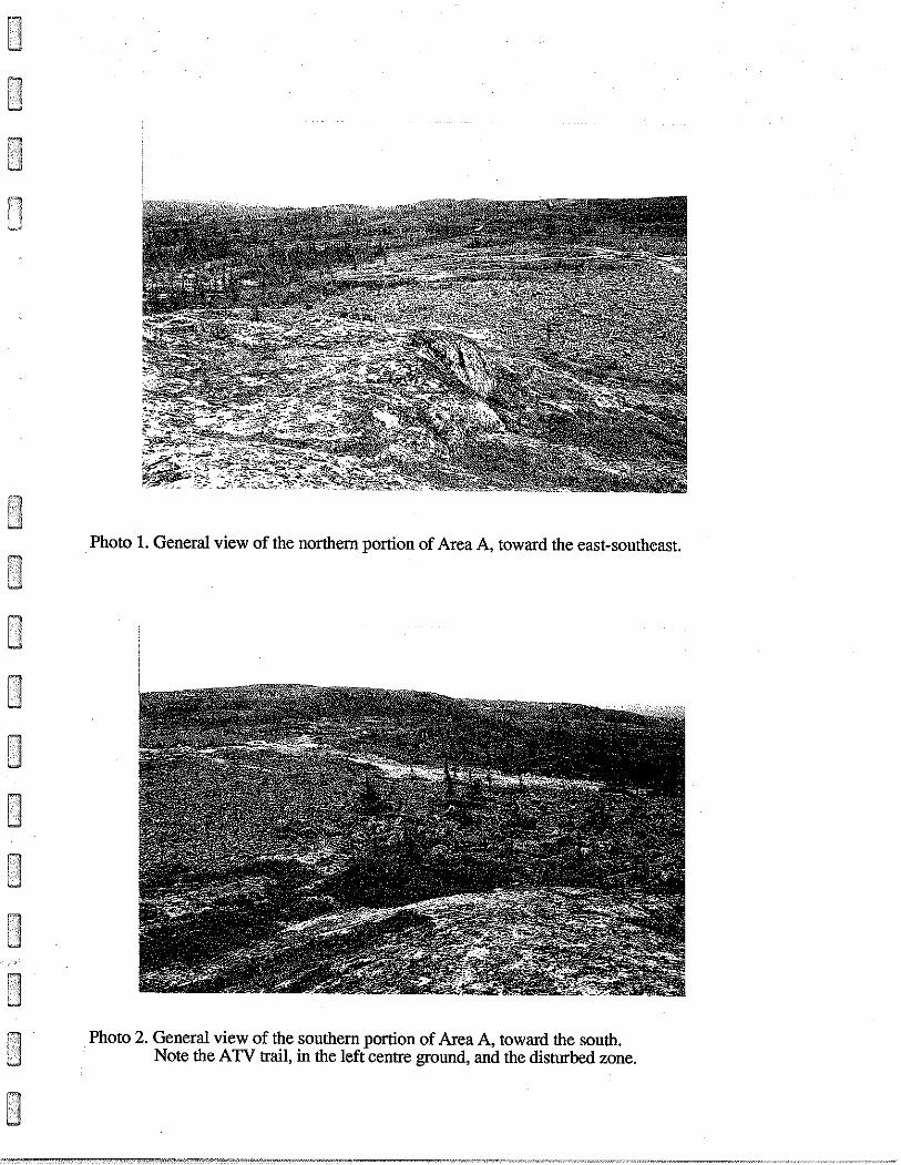
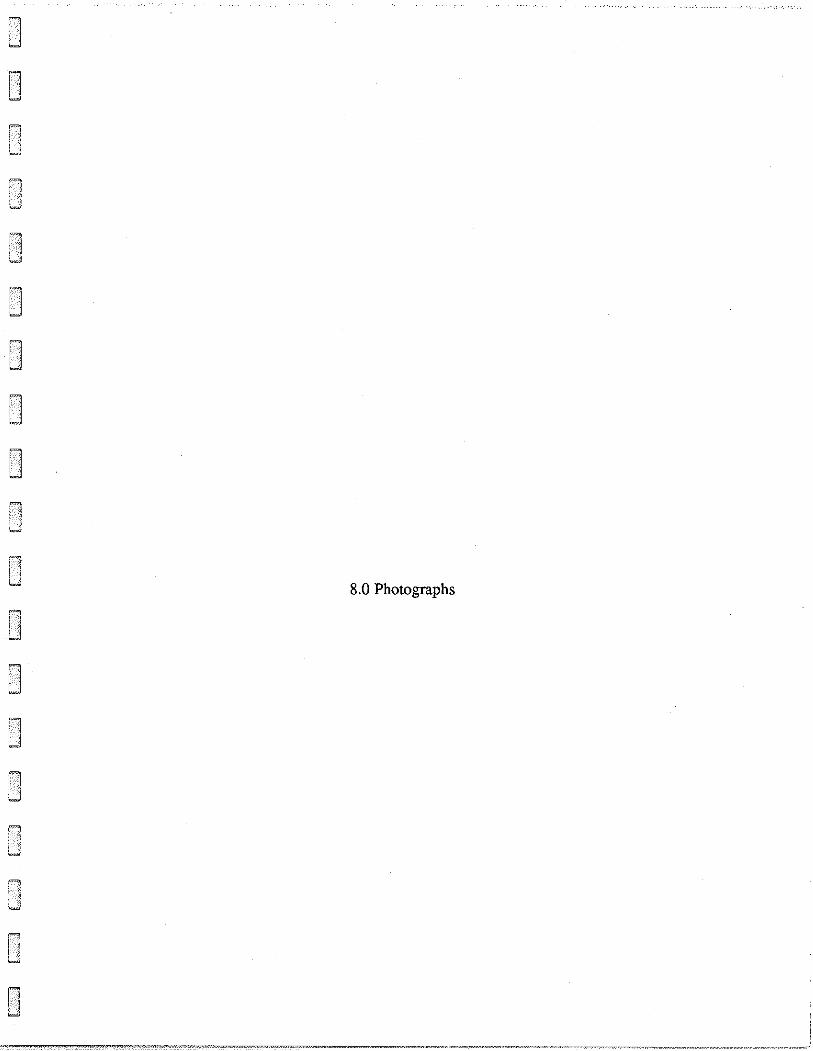
Photo 1. General view of the northern portion of Area A, toward the east-southeast.
U
Photo 2. General view of the southern portion of Area A, toward the south. Note the ATV trail, in the left centre ground, and the disturbed zone.
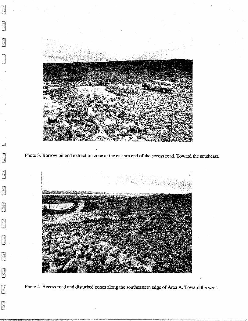
Photo 3. Borrow pit and extraction zone at the eastern end of the access road. Toward the southeast.
Photo 4. Access road and disturbed zones along the southeastern edge of Area A. Toward the west.
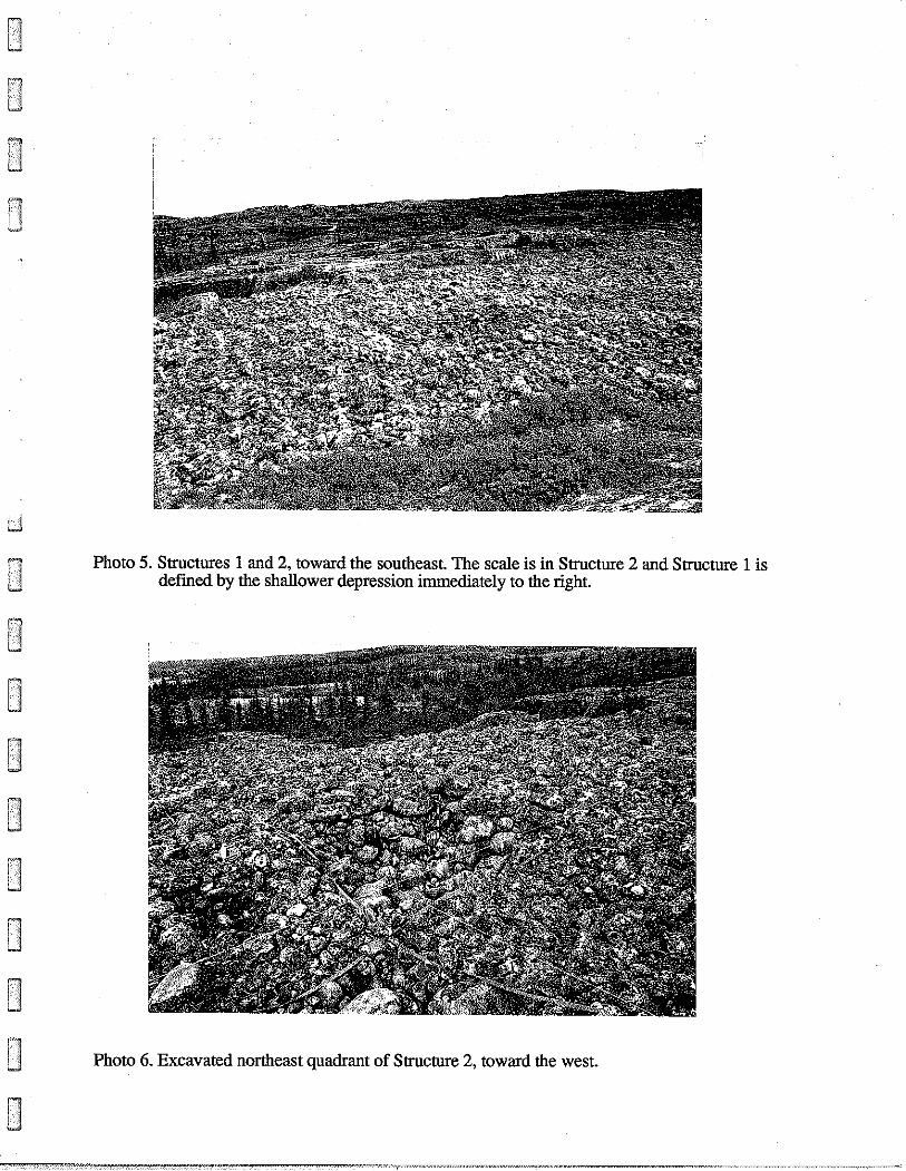
Photo 5. Structures 1 and 2, toward the southeast. The scale is in Structure 2 and Structure 1 is defined by the shallower depression immediately to the right.
Photo 6. Excavated northeast quadrant of Structure 2, toward the west.

Photo 7. Cache in Structure 2, toward the north-northwest. The scale is in the centre of the feature, defined by the larger boulders.
Photo 8. Excavated cache in Structure 2, toward the north.
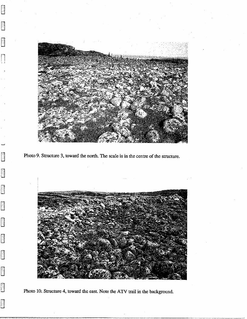
Photo 9. Structure 3, toward the north. The scale is in the centre of the structure.
Photo 10. Structure 4, toward the east. Note the ATV trail in the background.
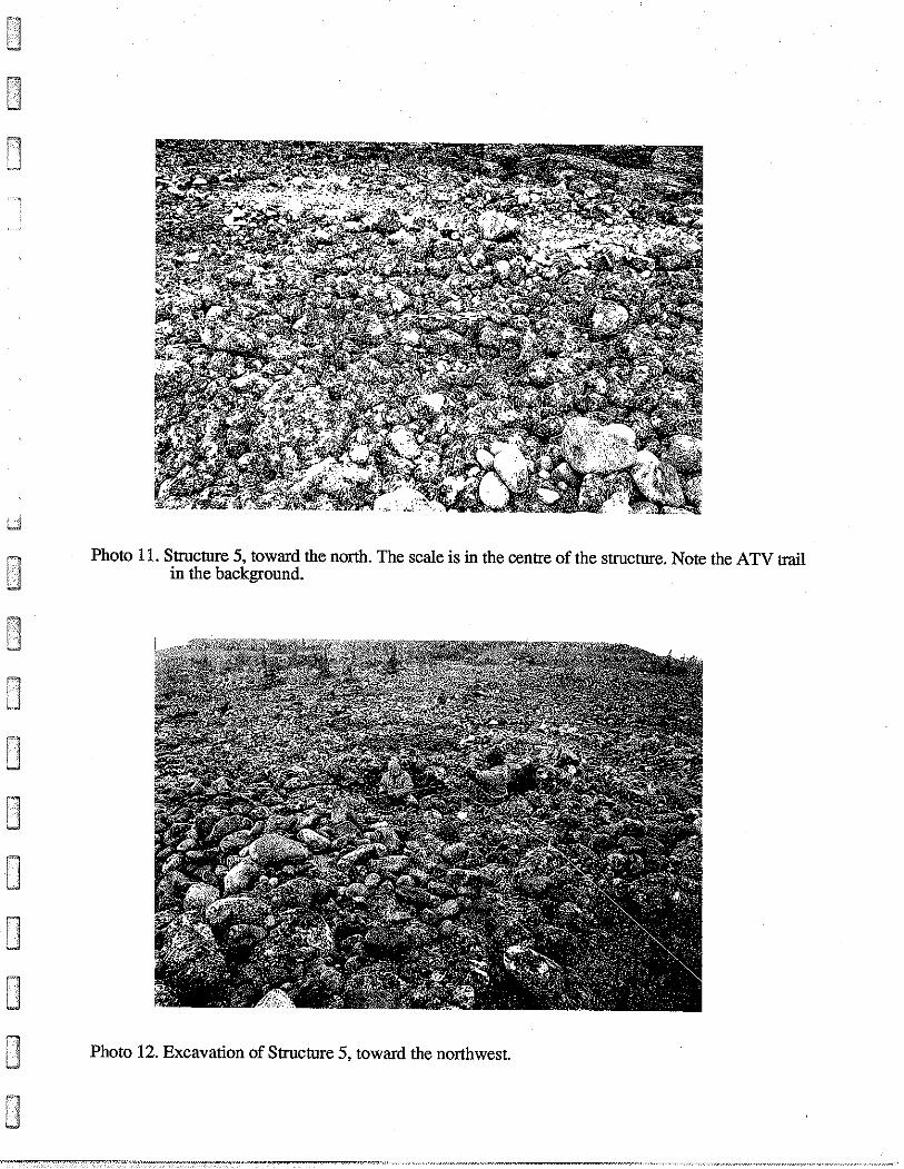
Photo 11. Structure 5, toward the north. The scale is in the centre of the structure. Note the ATV trail in the background.
Photo 12. Excavation of Structure 5, toward the northwest.
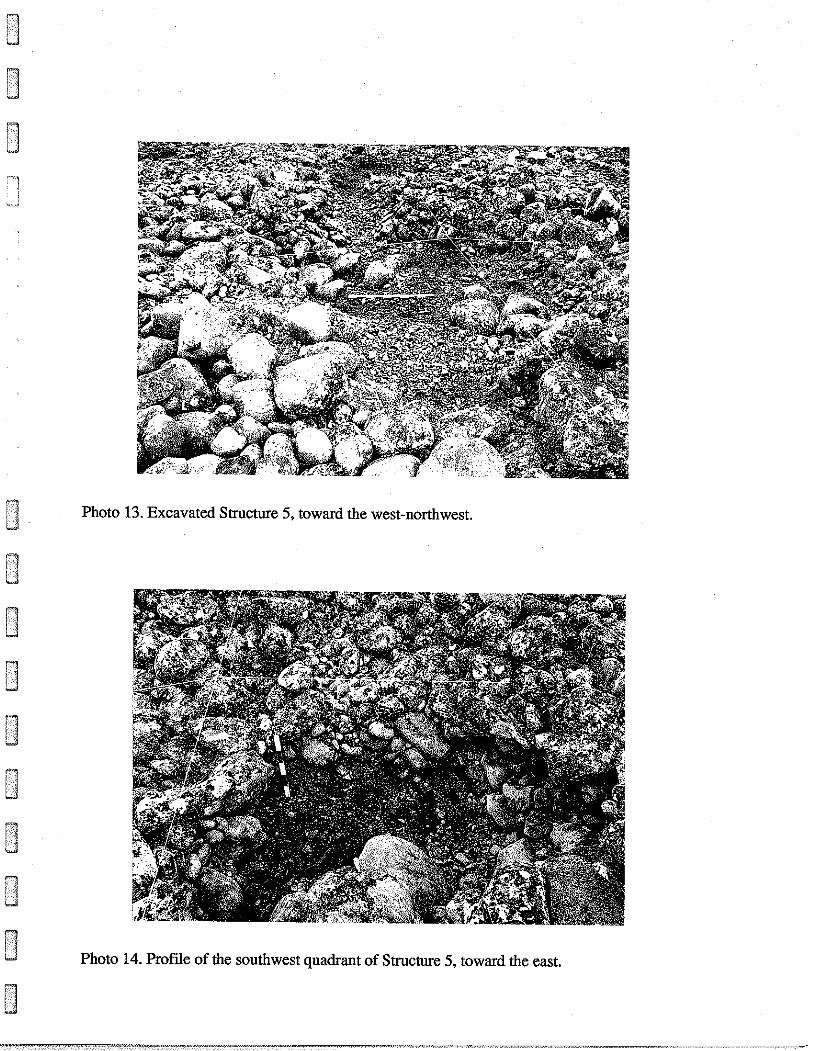
0 Photo 13. Excavated Structure 5, toward the west-northwest.
1 Photo 14. Profie of the southwest quadrant of Structure 5, toward the east.
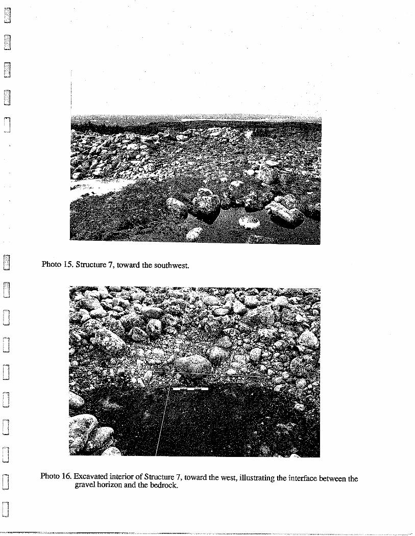
Photo 15. Structure 7, toward the southwest.
Photo 16. Excavated interior of Structure 7, toward the west, illustrating the interface between the gravel horizon and the bedrock.
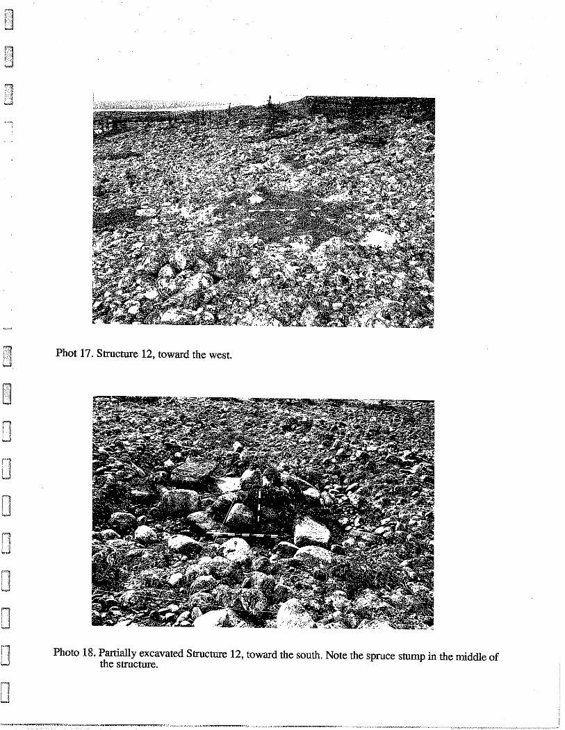
Phot 17. Structure 12, toward the west.
Photo 18. Partially excavated Structure 12, toward the south. Note the spruce stump in the middle of the structure.
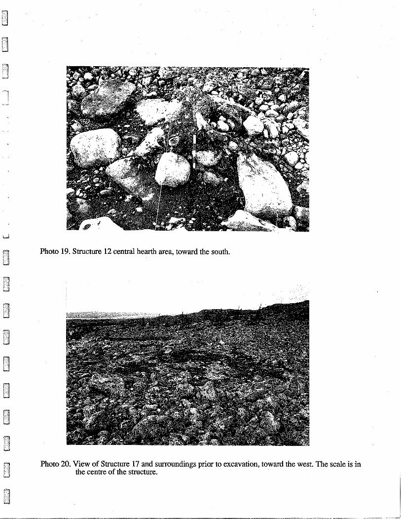
Photo 19. Structure 12 central hearth area, toward the south.
Photo 20. View of Structure 17 and surroundings prior to excavation, toward the west. The scale is in the centre of the structure.

Photo 21. DB-DD85-86, partially excavated northwestern portion of Structure 17, toward the south.
Photo 22. DE-DF85-86, partially excavated northeastern portion of Structure 17, toward the south.
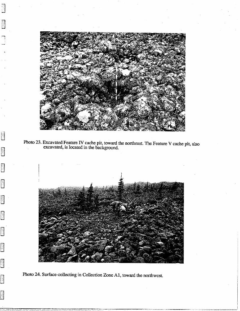
Photo 23. Excavated Feature N cache pit, toward the northeast. The Feature V cache pit, also excavated, is located in the background.
I Photo 24. Surface-collecting in Collection Zone Al, toward the northwest 1 I
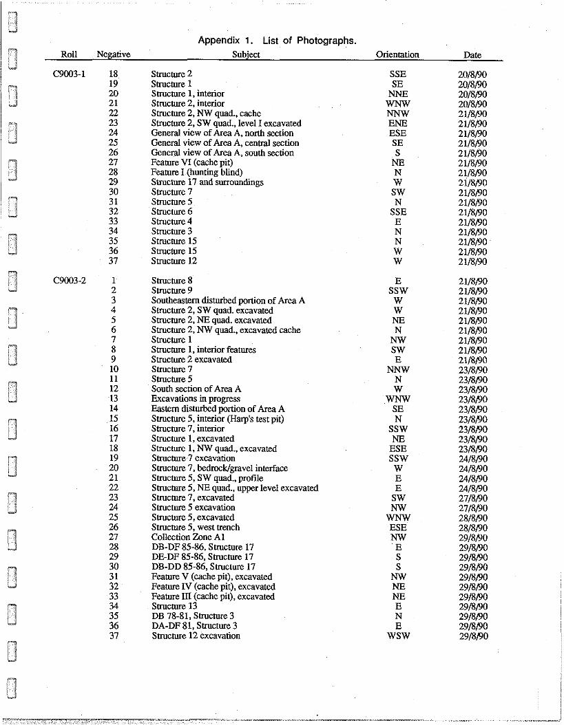
Appendix 1.
Roll Negative
Appendix 1. List of Photographs. Subject
Structure 2 Structure 1 Structure 1, interior Structure 2, interior Structure 2, NW quad., cache Structure 2, SW quad., level I excavated General view of Area A, nonh section General view of Area A, central section General view of Area A, south section Feature VI (cache pit) Feature I (hunting blind) Structure 17 and surroundings Structure 7 Structure 5 Structure 6 Structure 4 Structure 3 Structure 15 Structure 15 Structure 12
Structure 8 Structure 9 Southeastern disturbed portion of Area A Structure 2, SW quad. excavated Structure 2, NE quad. excavated Structure 2, NW quad., excavated cache Structure 1 Structure 1, interior features Structure 2 excavated Structure 7 Structure 5 South section of Area A Excavations in progress Eastern disturbed portion of Area A Structure 5, interior (Harp's test pit) Structure 7, interior Structure 1, excavated Structure 1, NW quad., excavated Structure 7 excavation Structure 7, bedrocklgravel interface Structure 5, SW quad., profile Structure 5, NE quad., upper level excavated Structure 7, excavated Structure 5 excavation Structure 5, excavated Structure 5, west trench Collection Zone A1 DB-DF 85-86, Structure 17 DE-DF 85-86, Structure 17 DB-DD 85-86, Structure 17 Feature V (cache pit), excavated Feature IV (cache pit), excavated Feature 111 (cache uit), excavated - . Structure 13 DB 78-81, Structure 3 DA-DF 81, Structure 3
37 Structure 1.2 excavation
Orientation
SSE SE NNE
NNW ENE ESE
W SW N
SSE
E SSW
W W NE N
NNW N W
WNW
-. SSW NE
ESE SSW
W E E
SW NW
WNW ESE NW ' E S
WSW
Date
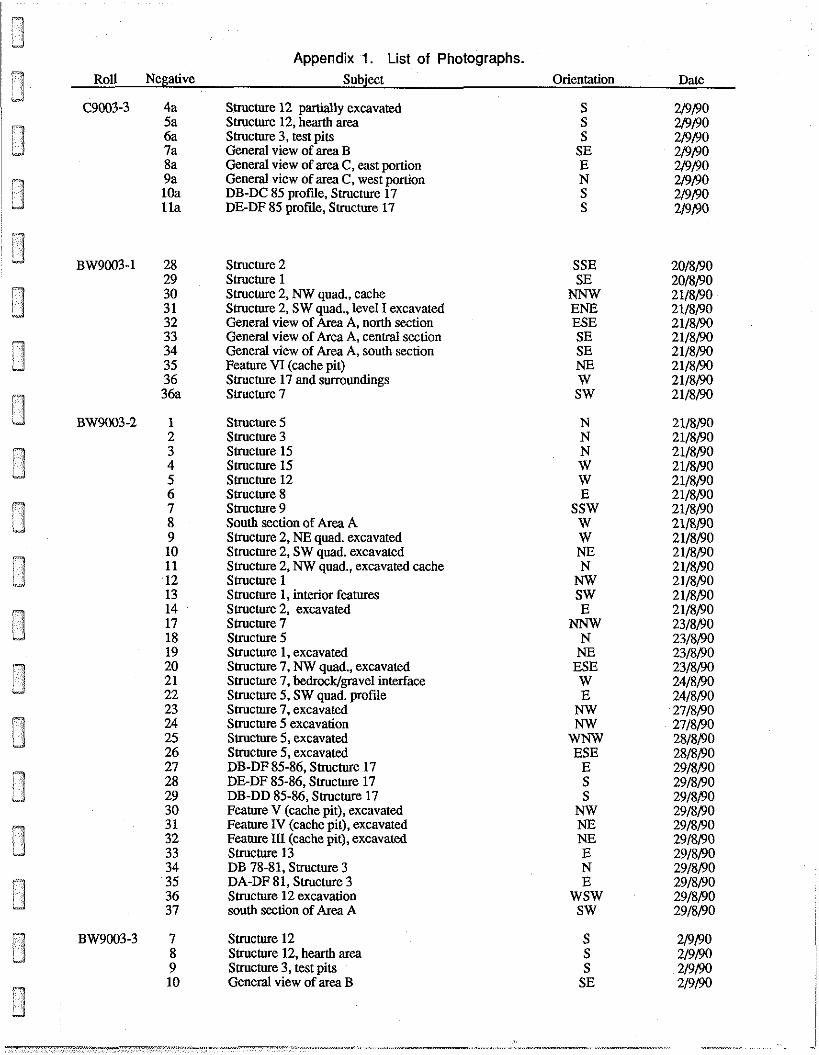
Appendix 1. List of Photographs. Roll Negative Subject Orientation Date
2/9/90 Structure 12 partially excavated Structure 12, hearth area Structure 3, test pits General view of area B General view of area C, east portion General view of area C, west portion DB-DC 85 profile, Structure 17 DE-DF 85 profile, Structure 17
Structure 2 SSE Structure 1 Structure 2, NW quad., cache Structure 2, SW quad., level I excavated General view of Area A, north section General view of Area A, central section General view of Area A, south section Feature VI (cache pit) Structure 17 and surroundings Structure 7
SE NNW ENE ESE
Structure 5 Structure 3 Structure 15 Structure 15 Structure 12 Structure 8 Structure 9 South section of Area A Structure 2, NE quad. excavated Structure 2, SW quad. excavated Structure 2, NW quad., excavated cache Structure 1 Structure 1, interior features Structure 2, excavated Structure 7 Structure 5 Structure 1, excavated Structure 7, NW quad., excavated Structure 7, bedrock/gravel interface Sttucture 5, SW quad. profile Structure 7, excavated Structure 5 excavation Structure 5, excavated Structure 5, excavated DB-DF 85-86, Sttucture 17 DE-DF 85-86, Structure 17 DB-DD 85-86, Structure 17 Feature V (cache pit), excavated Feature IV (cache pit), excavated Feature III (cache pit), excavated Structure 13 DB 78-81, Structure 3 DA-DF 81, Structure 3 Structure 12 excavation south section of Area A
Structure 12 Structure 12, hearth area Structure 3, test pits General view of area B
E SSW
W
E NNW
N NE
ESE W E
NW NW
WNW ESE
E S
WSW SW
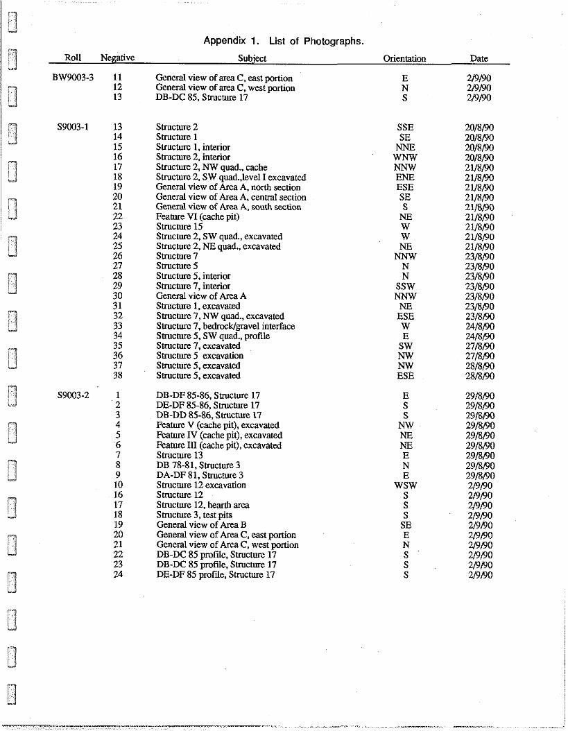
Appendix 1. List of Photographs.
Roll Negative Subject Orientation
BW9003-3 11 General view of area C, east portion 12 General view of area C, west portion 13 DB-DC 85, Structure 17
Structure 2 Structure 1 Structure 1, interior Structure 2, interior Structure 2, NW quad., cache Structure 2, SW quad.,level I excavated General view of Area A, north section General view of Area A, central section General view of Area A, south section Feature VI (cache pit) Structure 15 Structure 2, SW quad., excavated Structure 2, NE quad., excavated Structure 7 Structure 5 Structure 5, interior Structure 7, interior General view of Area A Structure 1, excavated Structure 7, NW quad., excavated Structure 7, bedrocklgravel interface Structure 5, SW quad., profile Structure 7, excavated Structure 5 excavation Structure 5, excavated Structure 5, excavated
DB-DF 85-86, Structure 17 DE-DF 85-86, Structure 17 DB-DD 85-86, Structure 17 Feature V (cache pit), excavated Feature IV (cache pit), excavated Feature 1.1 (cache pit), excavated Structure 13 DB 78-81, Structure 3 DA-DF 81, Structure 3 Structure 12 excavation Structure 12 Structure 12, hearth area Structure 3, test pits General view of Area B General view of Area C, east portion General view of Area C, west portion DB-DC 85 profde, Structure 17 DB-DC 85 profde, Structure 17 DE-DF 85 profde, Structure 17
SSE SE NNE
WNW NNW ENE ESE
W NE
NNW N N
SSW NNW
NE ESE W E
SW NW NW ESE
E WSW
S
Date
Appendix 2.
Appendix 2. Catalogue of Lithic Specimens. 1 . m
Cat No. Object Excavation Unit Level Coordinates (cm)
Microblade Microblade Microblade Microblade Microblade Microblade Microblade Microblade Microblade Microblade Microblade Microblade Microblade Microblade Microblade Microblade Microblade Microblade Microblade Microblade Microblade Microblade Microblade Microblade Microblade Microblade Microblade Microblade Micmblade Microblade Microblade Microblade Microblade Blade Blade Microblade core Microblade core Microblade core Microblade core Microblade core Microblade core Microblade core Microblade core Microblade core Point Point Point Point Point
DB 81 DE 83 DE 83 DC 85 DC 85 DD 85 DE 85 DE 85 DE 85 DE 85 DF 85 DF 85 DF 85 DB 86 DB 86 DB 86 DD 86 DD 86 DE 86 DF 86
Structure 7 Structure 7 Structure 12 Structure 12 Smcture 12 Structure 12 Structure 12 Structure 12 Structure 12 Structure 12 Structure 12
Collection Zone A1 Collection Zone A1
DE 84 DE 85 DE 84 DB 85 DB 85 DF 85 DF 85 DE 86
Structure 12 Structure 12
Collection Zone A1 DA 81 DE 83 DE 85 DE 85 DE 85
I1 I1 I1 11 I1 I1 I1 I1 I1 I11 I1 I11 111 I
I11 I11 I1 I1 I11 I1 I1 I1 IV IV I11 In 111 IV 111 I11 I11
surface surface
I1 I I1 I1 111 I1 nI I11 IV IV
surface I1 I1 I1 I1 I1
Raw Material
chert chert chert chert chert chert
quartz crystal quartz crystal
chert chert chert chert chert chert chert chert chert chert chert chert chert chert chert chert chert chert chert chert chert chert chert chert chert chert chert
quartz crystal chert chert chert
quartz crystal chert chert chert chert chert chert chert chert chert
Cat No. Object
Point Point Point Point Point Point Point Point Point Point Point Point Point Point Point Point Point Point Point Side blade Knife Knife Uniface Uniface Biface Fragment Biface fragment Biface fragment Biface fragment Biface Fragment Biface fragment Biface fragment Biface fragment Biface fragment Biface fragment Biface fragment Biface Fragment Biface fragment Biface fragment Biface fragment Biface fragment Biface fragment Biface fragment Biface fragment Biface fragment Biface fragment Biface fragment Reform Preform Burin Burin Burin
Appendix 2. Catalogue of Lithic Specimens.
Excavation Unit Level Caordinates
DE 85 n~ ~ 3 0 ~ 8 0 DE 85 I1 N551E5 DF 85 I1 N40/E20 DF 85 I1 N80/E70 DF 85 I1 N79E70 DF 85 I11 N55JE.45 DF 85 111 N90E.45 DF 85 111 N55JE.45 DF 85 111 N80/E20 DF 85 111 N5E90 DD 86 I1 N8O/E52 DF 86 I1 N5/E95
Structure 7 I1 S20/E20 Structure 12 IV N25/E20 Structure 12 & NSO/WSO Structure 12 IV N50E2.4
Collection Zone A1 surface Collection Zone A1 surface Collection Zone A1 surface
DF 85 11 N25JE.40 DF 85 I N65/E65
Collection Zone A1 surface DE 85 111 N95/E55 DE 86 111 N20/E5 DB 81 I1 N4O/E@ 40 DE 83 I1 N30/E50 DD 85 I1 N35/E25 DE 85 I N35E.40 DE 85 I N85/E5 DE 85 I1 N49/E5 DE 85 I1 N45tE68 DE 85 111 N10E30 DE 85 I11 N481E5 DE 85 111 N40lE55 DE 85 111 N80/E10 DF 85 I1 N55/E70 DB 86 I N79/E28 DB 86 111 N8O/E9 1 DD 86 111 N70/E20 DE 86 111 N55E5
Structure 5 N22/E135 Structure 12 IV N50/E150 Structure 12 IV N90/E50 Structure 12 111 N78W150
Collection Zone A l surface Collection Zone A l surface
DD 86 111 N70/E20 Collection Zone A1 surface
DE 81 m N47E75 DE 83 I N45/E65 DE 83 I1 N9O/E15
Raw Material
chert chert chert chert chert chert chert chert chert chert chert chert chert chert chert chert chert chert chert chert chert chert chert chert chert chert chert chert chert chert chert chert chert chert chert chert chert chert chert chert chert chert chert chert chert chert chert chert chert chert chert
1 Cat No. Object
Burin Burin Burin Burin Burin Burin Burin Burin Burin Burin Burin Burin Burin Burin Burin Burin Burin Burin Burin Burin Burin Burin Burin Burin Burin Burin Burin Burin Burin Burin spa11 Burin spall Burin spall Burin spall Burin spall Burin spall Burin spall Burin spall Burin spall Burin spall Burin spall Burin spall Burin spall Burin spall Burin spall Burin spall Burin spall Burin spall Burin spall Burin spall Burin spall Burin spall
Appendix 2. Catalogue of Lithic Specimens.
Excavation Unit Level Coordinates
DB 85 DB 85 DB 85 DC 85 DE 85 DE 85 DE 85 DE 85 DE 85 DE 85 DE 85 DE 85 DE 85 DF 85 DB 86 DC 86 DC 86 DC 86 DD 86 DD 86 DD 86 DE 86 DF 86
Structure 12 Structure 12 Structure 12
DE 85 Structure 12
DE 85 DB 81 DE 83 DE 83 DB 85 DC 85 DC 85 DC 85 DC 85 DD 85 DD 85 DD 85 DD 85 DE 85 DE 85 DE 85 DE 85 DE 85 DE 85 DE 85 DE 85 DE 85 DF 85
I I1 11 111 I I I I I I1 111 I11 I11 I11 I11 I1 111 111 I1 I11 111 I11 111 111 IV IV I
111 I11 I1 I1 I1 111 I1 I1 I1 I1 I1 I1 I1 111 I I1 I1 I1 I11 I n 111 111 111 111
N44/E58 N36/E86 N86/E39 N4/E8
NE quadrant NE quadrant NE quadrant NE quadrant NE quadrant
N45/E38 N13/E25 N95E20 N95/E85 N90/E40 N43/E43 N80/ESO N37/E28 N42/E26
NW quadrant N70/E20 N 7 0 W N63/E59 N45/E97 NOD137
N55iW100 N75/E50
NE quadrant N100/E100 N82/E89 N56/E93 N87/E19 N98/E5 N90/E95 N50/E65 N73/E84 N70W5 N55/E30 N77/E80 N90/E90 N70/E90 N94/E54
SE quadrant N43E36
NE quadrant SE quadrant
N16/E29 N18/E24 N64/E55 N80/E58 N90/E10 N44jl32
Raw Material
chert chert chert chert chert chert chert chert chert chert chert chert chert chert chert chert chert chert chert chert chert chert chert chert chert chert chert chert chert chert chert chert chert chert chert chert chert chert chert chert chert chert chert chert chert chert chert chert chert chert chert
Cat No.
152 153 154 155 156 157 158 159 160 161 162 163 164
* 165 166 167 168
ri169 w 170
171 F 172 11 173 X 174
175 176 177 178 179 180 181 182 183 184 185 186 187 188 189 190 191 192 193 194
&I95 196 197 198 199 200 20 1 202
Object
Burin spall Burin spall Burin spall Burin spall Burin spall Burin spall Burin spall Burin spall Burin spall Burin spall Burin spall Burin spall Burin spall End scraper End scraper End scraper End scraper End scraper End scraper End scraper End scraper End scraper End scraper End scraper Side scraper Adze blade Adze blade Adze blade Knife Retouched flake Retouched flake Retouched flake Used flake Retouched flake Used flake Retouched flake Retouched flake Retouched flake Retouched flake Retouched flake Retouched flake Used flake Retouched flake Retouched flake Retouched flake Retouched flake Used flake Retouched flake Retouched flake Retouched flake Used flake
Appendix 2. Catalogue of Lithic Specimens.
Excavation Unit Level Coordinates
DF 85 111 DF 85 I11 DF 85 I11 JX 86 I11 DD 86 I1 DD 86 I1 DD 86 I1 DD 86 I1 DD 86 1n DF 86 I1 DF 86 111 DF 86 DI
Structure 12 I11 DD 85 I1 DE 85 I DE 85 11 DF 85 I1 DF 85 I1 DF 85 111 DB 86 I1
Structure 5 I Structure 7 I1 Structure 12 IV
Collection Zone A1 surface DE 85 I DE 83 I1
Structure 2 Structure 2
DD 86 I1 DB 80 I1 DB 81 I1 DB 81 I1 DE 81 DE 83 I1 DE 84 I1 DD 85 I1 DE 85 I DE 85 I DE 85 I DE 85 I DE 85 I1 DE 85 I1 DE 85 I1 DE 85 I11 DF 85 I1 DF 85 I1 DF 85 I1 DF 85 I1 DF 85 111 DB 86 I DC 86 I11
N84E58 N70E38 N60iE41 N38E22
NW quadrant NW quadrant
N87B39 N60tE75 N70E20
NW quadrant N23E95 N10E10
NW quadrant N10E10 N15E25 N40E33 N55E95 N77P.60 N60rn5 N80/E50 N30iE4O s 2 0 m N15E65
N98D5 NE quadrant
N251E58 N36E36
NE quadrant NE quadrant SE quadrant NE quadrant NW quadrant
N60E35 N96/E40 N20E25
SW quadrant SW quadrant
N60E10 N ~ O ~ O N79D30 N13E22
Raw Material
chert chert chert chert chert chert chest chert chert chert chert chert chert chert chert chert chert chert chert chert chert chert chert chert chert
sandstone rnetabasalt rnetabasalt
chert chert chert chert chert chert chert chert
metabasalt chert chert chert chert chert chert chert chert chert chert chert chert chert chert

Cat. No. Object
Retouched flake Retouched flake Retouched flake Retouched flake Used flake Used flake Retouched flake Retouched flake Used flake Retouched flake Retouched flake Knife Retouched flake Retouched flake Used flake Knife Retouched flake Retouched flake Flake wre Flake core make core Flake wre Flake wre Flake wre Flake core Hammerstone Used flake Buriu Microblade core Retouched flake Retouched flake
Appendix 2. Catalogue of Lithic Specimens.
Excavation Unit Level Coordinates
DC 86 n1 DD 86 I1 DD 86 I11 DE 86 n
Structure 2 Structure 2 Structure 12 Structure 12 IV Structure 12 111 structure 12 n~ Structure 12 IV
Collection Zone A1 surface Collection Zone A1 surface Collection Zone A1 surface Collection Zone A1 surface Collection Zone A1 surface Collection Zone A1 surface Collection Zone A1 surface
DE 84 I1 DE 85 I DF 85 I DF 85 I1 DF 86 111
Structure 12 IV Collection Zone A1 surface
DD 86 I11 Structure 5 I Structure 12 IV Structure 12 IV Structure 5 I Structure 5 I
N26E30 N25/E36 N63E94
SW quadrant N18E18 NOm'110
NE N35/E50 NE quadrant
S80E110 NW quadrant NW quadrant
Raw Material
chert chert chert chert chert chert chert chert chert chert chert chert chert chert chert chert chert chert chert chert chert chert chert chert chert
undetermined chert
quartz crystal quartz crystal
chert chert
Appendix 2. Catalogue of Lithic Specimens.
2. Waste makes
Cat.No. Excavation Unit Quadrant Level Raw Material Number of flakes
I 111 I11 I11 n I I11
surface I I I I1 I I1 I I1 I1 I1 I1 I1 I I I I1 I1 I1 I1 I1 I1 I1 I1 I1 I1 I1 I1 I1 I I1 I1 n I1 I1 I1 I1
chert chert chert chert chert chert chert chert chert chert chert chert chert chert chert chert chert chert chert chert chert chert chert chert chert chert chert chert
quartz crystal chert chert
quartz crystal chert chert chert chert chert chert chert chert chert chert
quartz crystal
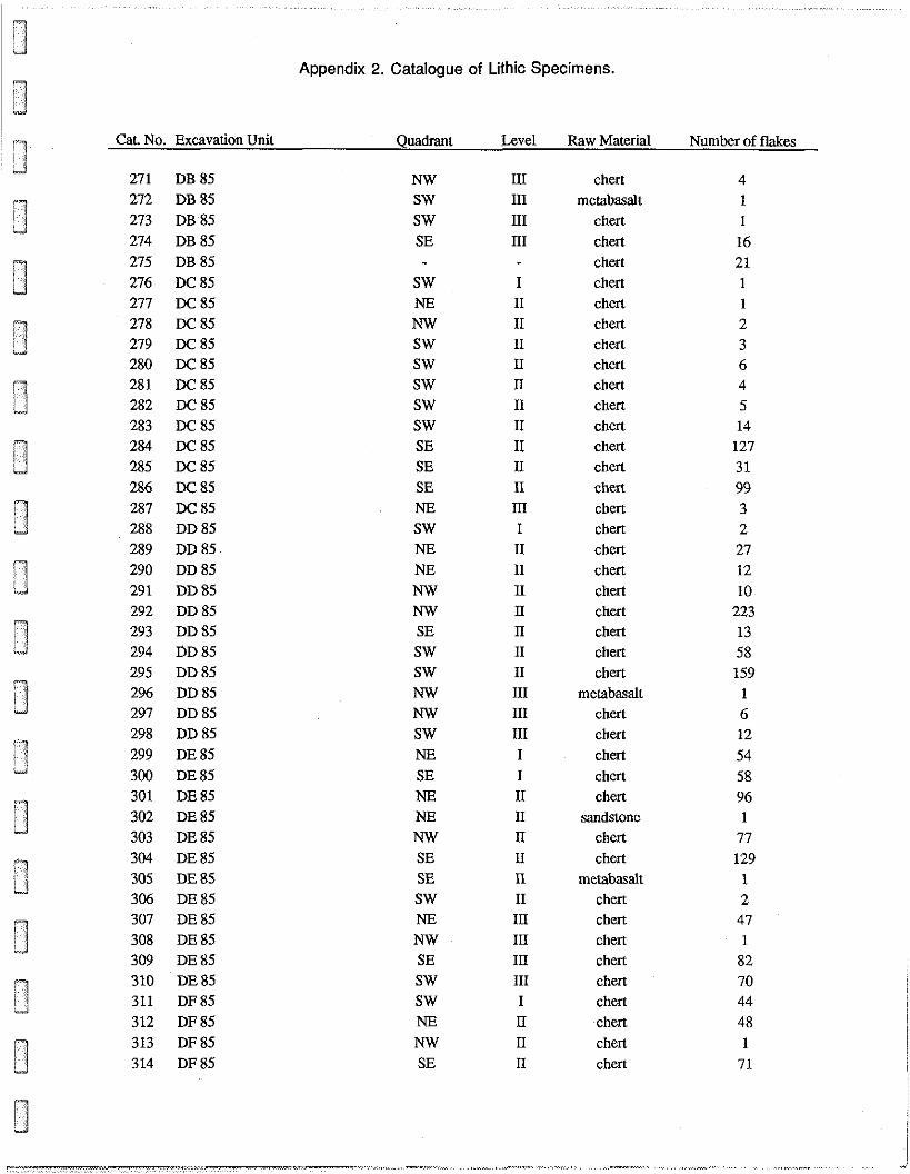
Appendix 2. Catalogue of Lithic Specimens.
Cat. No. Excavation Unit
271 DB85 272 DB 85 273 DB 85 274 DB 85 275 DB 85 276 DC 85 277 DC 85 278 DC 85 279 DC 85 280 DC 85 281 DC85 282 DC 85 283 DC 85 284 DC 85 285 DC 85 286 DC 85 287 DC 85 288 DD85 289 DD 85 290 DD 85 291 DD85 292 DD 85 293 DD85 294 DD 85 295 DD 85 296 DD 85 297 DD 85 298 DD 85 299 DE85 300 DE85 301 DE85 302 DE85 303 DE 85 304 DE85 305 DE85 306 DE85 307 DE85 308 DE 85 309 DE85 310 DE85 311 DF85 312 DF85 313 DF85 314 DF85
Quadrant Level Raw Material
chert metabasalt
chert chert chert chert chert chert chert chert chert chert chert chert chert chert chert chert chert chert chert chert chert chert chert
metabasalt chert chert chert chert chert
sandstone chert chert
metabasalt chert chert chert chert chert chert chert chert chert
Number of flakes

Cat No.
Appendix 2. Catalogue of Lithic Specimens.
Excavation Unit Quadrant Level Raw Material
chert chert chert
metabasalt chert chert
quartz crystal quartz crystal
chert chert chert chert chert chert chert chert chert chert
quartz crystal chert chert chert chert chert chert chert chert chert chert chert chert
sandstone chert chert chert
metabasalt chert chert chert
sandstone chert
sandstone chert chert
Number of flakes
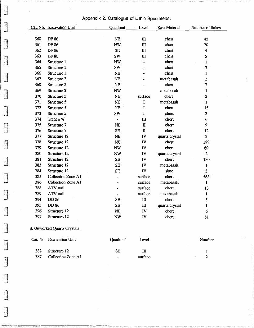
Appendix 2. Catalogue of Lithic Specimens.
Cat. No. Excavation Unit Quadrant Level Raw Material
DF 86 DF 86 DF 86 DF 86 Structure 1 Structure 1 Structure 1 Structure 2 Structure 2 Structure 2 Structure 5 Structure 5 Structure 5 Structure 5 Trench W Structure 7 Structure 7 Structure 12 Structure 12 Structure 12 Structure 12 Structure 12 Structure 12 Structure 12 Collection Zone A1 Collection Zone A1 ATV trait ATV trail DD 86 DD 86 Structure 12 Structure 12
3. Ynworked Ouam Crystals
I11 111 I11 111
surface I I I
111 I1 n IV IV IV IV IV IV N
surface surface surface surface
111 111 IV IV
Cat No. Excavation Unit Quadrant Level
382 Structure 12 SE I11 387 Collection Zone A1 - surface
chert chert chert chert chert chert chert
metabasalt chert
metabasalt chert
metabasalt chert chert chert chert chert
quartz crystal chert chert
quartz crystal chert
metabasalt slate chert
metabasalt chert
metabasalt chert
quartz crystal chert chert
Number of flakes
Number